

Page 1
Installation Instructions
IMPORTANT
Low-profile Connector Kit for I/O and
Cascading Safe Torque-off Signals
Catalog Number 2090-K6CK-D44S0
About the Low-profile Connector Kit
The low-profile 44-pin connector kit provides termination points for I/O and safe torque-off
connections on the IOD connector of Kinetix® 6200 and Kinetix 6500 servo drives. When used
with the 2094-xx02x-M0x-S0 (safe torque-off ) control modules, you can use this kit and
2090-CS0DSDS-AAxx safe torque-off cables to cascade the safe torque-off signals from one
drive to another. This kit also includes two identical motion-allowed jumpers that you install
when the safe torque-off functionality of 2094-xx02x-M0x-S0 control modules is not desired.
This kit and the cables apply to only 2094-xx02x-M0x-S0 (safe torque-off) control modules.
They do not apply to 2094-xx02x-M0x-S1 (safe speed) control modules.
In addition, this kit provides access to the digital input connections for standard cables or
discrete wires. Refer to the Kinetix 6200 and Kinetix 6500 Modular Multi-axis Servo Drive User
Manual, publication 2094-UM002
Refer to the Kinetix 6200 and Kinetix 6500 Safe Torque-off Safety Reference Manual,
publication 2094-RM002
, for more information on wiring safe torque-off functions.
, for more information on wiring digital inputs.
Safe Torque-off Cables
Safe torque-off cables for cascading drive-to-drive connections are available in three lengths.
Cable Cat. No. Length Description
2090-CS0DSDS-AA02 0.2 m (7.1 in.) Drive-to-drive connections (single-wide IAM or AM power module)
2090-CS0DSDS-AA03 0.3 m (1.0 ft) Drive-to-drive connections (double-wide IAM or AM power module)
2090-CS0DSDS-AA10 1.0 m (3.2 ft) Connect to next 2094 power rail or other safe torque-off device
Page 2
2 Low-profile Connector Kit for I/O and Cascading Safe Torque-off Signals
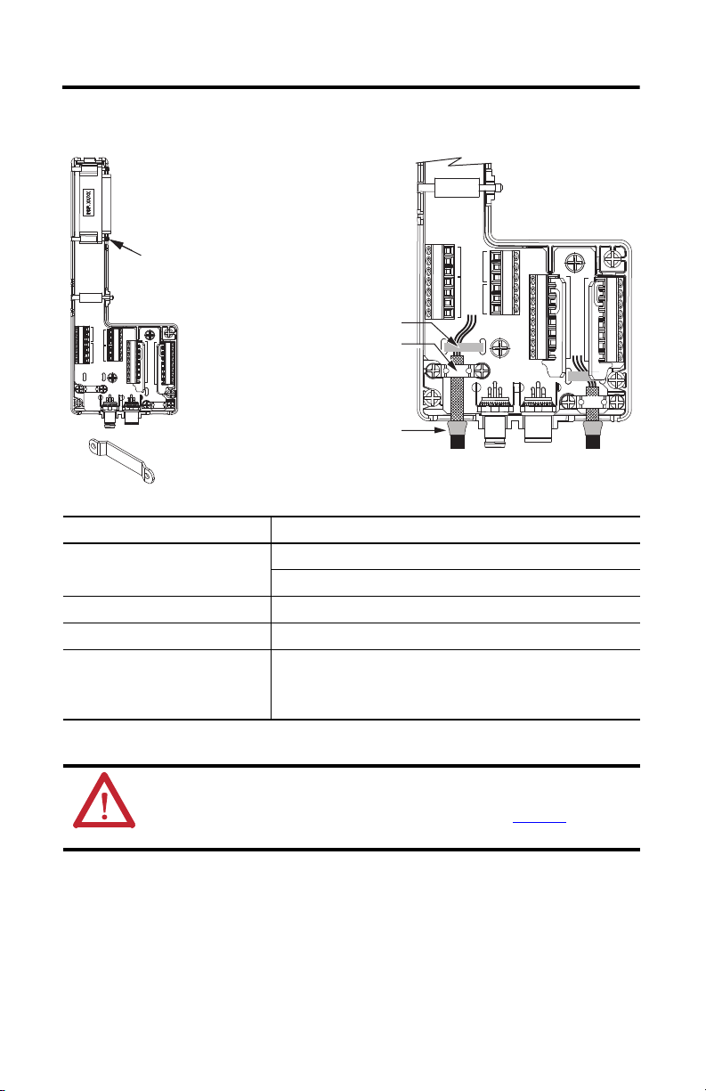
Follow these steps to form a compact
connection on I/O and safety wires.
1. Push the insulation down-and-over itself.
2. Move the insulation so it butts against the
outside wall of the cover.
3. Tape or shrink-wrap the end of the
insulation to the cable.
Mounting
Screws (3)
If necessary, turn clamps over
to hold small wires securely.
Shrink-wrapped Insulation
Use shield clamps (2) to maximize contact with
cable shield for high-frequency bonding.
Use tie wraps (2) for stress relief.
I/O
Cable/Wires
Cascadin g S0
Safe-off Cables
Safety
Cable/Wire s
Install the Low-profile Connector Kit
P2
P4
40
40
42
44
39
39
41
40
0
Attribute 2090-K6CK-D44S0
Cascading cable connectors
Screw terminal wire size 0.2…0.75 mm
Recommended wire strip length 5 mm (0.2 in.) single conductor
Recommended torque
P5
P6
39
27
14
39
28
25
43
19
17
40
20
26
23
P3
P1
Mounting screw
Ter mi nal scr ew s
Clamp and cover screws
18
24
15
21
0
22
0
M8 sockets (female) S0 output connector
M8 pins (male) S0 input connector
2
(24…18 AWG)
0.4 N•m (3.5 lb•in)
0.2 N•m (2.1 lb•in)
0.4 N•m (3.5 lb•in)
P2
P4
40
42
39
39
41
40
0
40
44
P5
39
39
43
40
P3
P1
S0INS0
OUT
P6
27
28
19
20
23
24
21
22
14
25
17
26
18
15
0
0
ATTENTION: This connector kit contains electrostatic discharge (ESD) sensitive parts that can be
damaged if you do not follow ESD control procedures. If you are unfamiliar with ESD control
procedures, refer to Guarding Against Electrostatic Damage, publication 8000-4.5.2
applicable ESD protection handbook.
Rockwell Automation Publication 2090-IN043A-EN-P - December 2011
, or any other
Page 3

Low-profile Connector Kit for I/O and Cascading Safe Torque-off Signals 3
Motion-allowed Jumper Installation Example
for P5 and P6 Connectors (P6 is shown)
Applies to 2094-xx02x-M0x-S0
(safe torque-off) control modules. Kit includes
two identical jumpers. Install jumpers when
safe torque-off functionalit y is not used.
Pin numbering corresponds to the IOD (44 pin) connector. Pins 39 and 40 are given multiple
terminals to accommodate connections for each of the inputs.
P5 (safety) Terminal Block
Drive Pin Kit Pin Signal
IOD-19 P5-19 SS_IN_CH0
IOD-20 P5-20 SS_IN_CH1
IOD-21 P5-21 SS_OUT_CH0
IOD-22 P5-22 SS_OUT_CH1
IOD-23 P5-23 SS_IN_CH2
IOD-24 P5-24 SS_IN_CH3
IOD-27 P5-27 TEST_OUT_0
IOD-28 P5-28 TEST_OUT_1
P6 (safety) Terminal Block
IOD-14 P6-14 24VPWR
IOD-15 P6-15 24VCOM
IOD-17 P6-17 SPWR
IOD-18 P6-18 SCOM
IOD-25 P6-25 RESET_REF
IOD-26 P6-26 RESET_IN
Shield P6-0 Shield
Shield P6-0 Shield
P1 (I/O) Terminal Block
Drive Pin Kit Pin Signal
IOD-39 P1-39 24VPWR
IOD-41 P1-41 INPUT 1
IOD-40 P1-40 24VCOM
Shield P1-0 Shield
P2 (I/O) Terminal Block
IOD-40 P1-40 24VCOM
IOD-42 P1-42 INPUT 2
IOD-39 P1-39 24VP WR
P3 (I/O) Terminal Block
IOD-39 P1-39 24VP WR
IOD-43 P1-43 INPUT 3
IOD-40 P1-40 24VCOM
P4 (I/O) Terminal Block
IOD-40 P1-40 24VCOM
IOD-44 P1-44 INPUT 4
IOD-39 P1-39 24VP WR
Connector Data
P2
P4
40
42
39
39
41
40
0
40
44
39
39
43
40
P3
P1
S0INS0
P5
P6
27
28
19
20
23
24
21
22
OUT
14
25
17
26
18
15
0
0
14
25
17
26
18
15
0
0
Rockwell Automation Publication 2090-IN043A-EN-P - December 2011
Page 4

Cascading Safe Torque-off Signals
2090-CS0DSDS-AAxx
Cascading Safe Torque-off Cables
Input cable from previous
2094 power rail or
other cascading device.
Output cable to next
2094 power rail or
other cascading device.
2094-BCxx-Mxx-M
IAM Power Module
with
2094-xx02x-M0x-S0
Control Mo dule
2094-BMxx-M
AM Power Module
with
2094-xx02x-M0x-S0
Contro l Modules (2)
2094-K6CK-D44S0
Cascadin g Connector Kit s (3)
2094-K6CK-D15M
Feedback Connector Kits (3)
I/O Wiring
Input Connector
Output Connector
Safety Wiring
Bottom View
All right-angled cable connectors are keyed to exit left as shown. Cables loop back and cascade to
the next drive or other device. Route input wires through the I/O and safety wiring access holes.
Additional Resources
These documents contain additional information concerning related products from Rockwell
Automation.
Resource Description
Kinetix 6200 and Kinetix 6500 Safe Torque-off Servo
Drives Safety Reference Manual, publication 2094-RM002
Kinetix 6200 and Kinetix 6500 Modular Multi-axis Servo
Drive User Manual, publication 2094-UM002
Industrial Automation Wiring and Grounding Guidelines,
publication 1770-4.1
Information on wiring, configuring, and troubleshooting the safe
torque-off features of your Kinetix 6200 and Kinetix 6500 drives.
Information on installing, configuring, startup, troubleshooting, and
applications for your Kinetix 6200 and Kinetix 6500 servo drives.
Provides general guidelines for installing a Rockwell Automation
industrial system.
You can view or download publications at http://www.rockwellautomation.com/literature/
order paper copies of technical documentation, contact your local Allen-Bradley distributor or
Rockwell Automation sales representative.
Allen-Bradley, Kinetix, Rockwell Software, and Rockwell Automation are trademarks of Rockwell Automation, Inc.
Trademarks not belonging to Rockwell Automation are property of their respective companies.
Rockwell Automation Publication 2090-IN043A-EN-P - December 2011
Copyright © 2011 Rockwell Automation, Inc. All rights reserved. Printed in the U.S.A.
. To
 Loading...