

Page 1

Installation Instructions
Standard Power Cables with
SpeedTec DIN Connector Type 940
Catalog Number 2090-CPBM7DF-06AAxx, 2090-CPBM7DF-08AAxx,
2090-CPBM7DF-10AAxx, 2090-CPWM7DF-08AAxx,
2090-CPWM7DF-10AAxx
Top ic Page
Important User Information 2
Before You Begin 3
Install Cables 4
Connector Pinout Diagrams 6
Specifications 7
Additional Resources 8
About Standard Power Cables
Standard motor power cables, with or without brake connections, have a 40 mm (1.6 in.)
SpeedTec DIN connector at the motor end, and flying leads at the drive end. These cables can be
bent or reformed during installation or maintenance, but should not be used in a continuous flex
operation.
Page 2
2 Standard Power Cables with SpeedTec DIN Connector Type 940
Important User Information
Solid state equipment has operational characteristics differing from those of electromechanical equipment.
Safety Guidelines for the Application, Installation and Maintenance of Solid State Controls, publication
SGI-1.1
, available from your local Rockwell Automation sales office or online at
http://rockwellautomation.com/literature
equipment and hard-wired electromechanical devices. Because of this difference, and also because of the
wide variety of uses for solid state equipment, all persons responsible for applying this equipment must
satisfy themselves that each intended application of this equipment is acceptable.
In no event will Rockwell Automation, Inc. be responsible or liable for indirect or consequential damages
resulting from the use or application of this equipment.
The examples and diagrams in this manual are included solely for illustrative purposes. Because of the many
variables and requirements associated with any particular installation, Rockwell Automation, Inc. cannot
assume responsibility or liability for actual use based on the examples and diagrams.
No patent liability is assumed by Rockwell Automation, Inc. with respect to use of information, circuits,
equipment, or software described in this manual.
Reproduction of the contents of this manual, in whole or in part, without written permission of Rockwell
Automation, Inc., is prohibited.
Throughout this manual, when necessary, we use notes to make you aware of safety considerations.
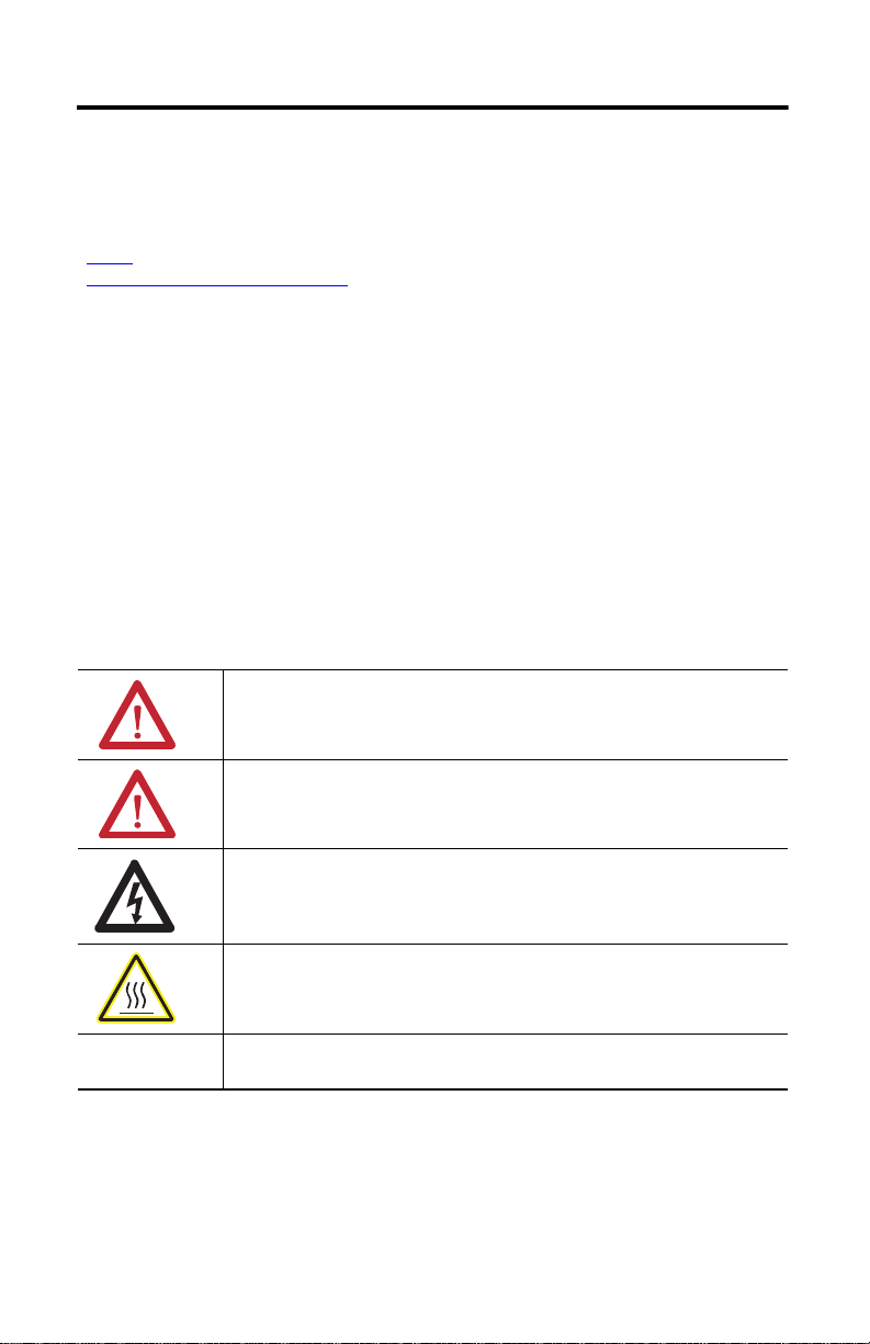
WARNING: Identifies information about practices or circumstances that can cause an
explosion in a hazardous environment, which may lead to personal injury or death,
property damage, or economic loss.
, describes some important differences between solid state
ATTENTION: Identifies information about practices or circumstances that can lead to
personal injury or death, property damage, or economic loss. Attentions help you
identify a hazard, avoid a hazard and recognize the consequences.
SHOCK HAZARD: Labels may be on or inside the equipment, for example, drive or
motor, to alert people that dangerous voltage may be present.
BURN HAZARD: Labels may be on or inside the equipment, for example, drive or
motor, to alert people that surfaces may reach dangerous temperatures.
IMPORTANT Identifies information that is critical for successful application and understanding of
the product.
Publication 2090-IN023A-EN-P - September 2010
Page 3
Standard Power Cables with SpeedTec DIN Connector Type 940 3
Before You Begin
Remove all packing material from within and around the item. After unpacking, verify the
catalog number against the purchase order, and visually inspect the cable and each connector for
damage. If necessary, notify the carrier of any shipping damage immediately.
Cables are stored and shipped in a coil, and will retain this shape unless you allow the cable to
straighten itself. To straighten a cable, hang a short cable from its mid-point or lay a long cable on
the floor in a straight line. Any coiling that persists in the cable should relax within the next
twenty-four hours. Doing this results in a cable that is easier to install.
Observe the following precautions when installing the cables in a servo system. Failure to observe
these safety notices could result in personal injury or damage to the motor and equipment.
ATTENTION: Arcing or unexpected motion can occur if the power, brake, or
feedback cables are connected or disconnected while power is applied to the
drive.
Always remove power to the servo drive before connecting or disconnecting
cables at the drive or at the motor.
ATTENTION: To avoid the hazard of electrical shock, make sure shielded power
cables are grounded at a minimum of one point. To prevent the build-up of
electrical energy, factory supplied power cables use one of these grounding
techniques:
• The overall shield is bonded to the connector housing.
• A section of the overall shield is exposed for connection to ground.
• The overall shield is connected to a ground wire.
If the exposed cable braid or a ground wire is present, connect it to the power
cable clamp, housing, or another suitable chassis ground on the drive.
ATTENTION: The maximum length of cabling between the drive and the motor
must not exceed 90 m (295.5 ft), and a maximum of two (2) extension cables
may be connected between a drive and a motor. Refer to Kinetix Motion Control
Selection Guide, publication GMC-SG001
ATTENTION: Do not tightly gather or coil the excess length of a power cable.
Heat is generated within a cable whenever power is applied. Always position a
power cable so it may freely dissipate any heat.
A power cable should not be coiled, except for temporary use when building or
testing a machine. If you temporarily coil a power cable, you must also derate
the cable to meet local code or follow a authoritative directive, such as
Engineering Section 310.15(C) of the NEC Handbook.
Publication 2090-IN023A-EN-P - September 2010
, for additional information.
Page 4

4 Standard Power Cables with SpeedTec DIN Connector Type 940
Limited
Bend Zone
Installation
Area
Installation Area
Label
(6 Places)
Exposed
Shields
Refer to Specifications
for recommended
Installation Area and Bend Zone values.
Shrink Wrap
ATTENTION: The examples in this publication show all the available
connections, some of which may not be appropriate for your specific
installation. Refer to your drive installation or user manual for recommended
wire trim lengths, and wiring examples appropriate to your drive and motor
application.
Do not connect unused wires. Unused wires may be trimmed and finished as
necessary to prevent accidental contact with other wires or wire shields, or with
a ground connection.
Install Cables
Follow these steps when installing a cable.
1. Identify the recommended installation areas and the correct offset from features before
beginning any cable bend. Features include these areas on the cable:
• Connectors
• Transitions from exposed wire to insulation (for example, flying leads)
• Exposed cable ground shields
The offset from these features should be greater than or equal to (>1x) the cable
diameter.
2. Keep cable bends within the bend radius specified on page
3. When installing a cable observe these restrictions:
• The bend zone is the area in which the cable can bent to its specified bend radius.
• The installation areas require strain relief to minimize cable flexing, and to reduce
the possibility of cable fatigue where the cable connects to other components.
4. Identify each connection on a cable by attaching a label around the outer insulation of
each wire adjacent to the drive connection.
Publication 2090-IN023A-EN-P - September 2010
7.
Page 5

Standard Power Cables with SpeedTec DIN Connector Type 940 5
IMPORTANT
SpeedTec Plug
Remove the O-ring from an
extension cable receptacle (shown)
or a motor connector that is SpeedTec ready.
With This Plug Do This
Threaded Plug
Verify the O-ring is installed
only when mating with a threaded plug.
O-ring Removal
The type of plug on the connecting cable determines whether an O-ring is required on the motor
connector or the extension cable receptacle.
The O-ring dampens the effects of vibration at the connection.
This creates a more secure connection with the threaded plug.
Publication 2090-IN023A-EN-P - September 2010
Page 6

6 Standard Power Cables with SpeedTec DIN Connector Type 940
Twisted Wire Pair
360° shield-to-ground
connections required.
To
Motor
Connector
Backshell
Shielded
360°
Shield
Wire Connection
To
Drive
(1)
(1)
(1)
(1)
Brown
Black
Blue
Green/Yellow
Shield
U
V
W
U
V
W
PE
(2)
360° shield-to-ground
connections required.
To
Motor
Connector
Backshell
Shielded
360°
Shield
Wire Connection
To
Drive
Connector Pinout Diagrams
These diagrams provide wire colors and pinouts for the standard power cables.
2090-CPBM7DF-xxAAxx
(1)
U
V
W
+
-
(1) Wire gauge and connector keying varies based on motor and power requirements. Refer to Kinetix Motion Control Selection
Guide, publication GMC-SG001
, for additional information.
(2) The Protective Earth (PE) power wire also may be labelled Ground (GND).
2090-CPWM7DF-xxAAxx
Brown
(1)
Black
(1)
Blue
(1)
Green/Yellow
18 AWG White
18 AWG Black
Shield
U
V
W
PE
MBRK+
MBRK-
(2)
(1) Wire gauge and connector keying varies based on motor and power requirements. Refer to Kinetix Motion Control Selection
Guide, publication GMC-SG001
, for additional information.
(2) The Protective Earth (PE) power wire also may be labelled Ground (GND).
Publication 2090-IN023A-EN-P - September 2010
Page 7

Standard Power Cables with SpeedTec DIN Connector Type 940 7
Specifications
Additional specifications for each cable are available in the Kinetix Motion Control Selection
Guide, publication GMC-SG001.
2090-CPBM7DF-xxAAxx Specifications
Attribute Value
Wire Size 10 AWG 8 AWG 6 AWG
Diameter 16.8 mm (0.66 in.) 20 mm (0.79 in.) 24.3 mm (0.96 in.)
Bend Radius 170 mm (7.0 in.) 200 mm (8.0 in.) 245 mm (9.5 in.)
(1)
Installation Areas
(1) The installation areas are approximately 300 mm (12 in.) in length at both ends of the cable. Secure this area with a rigid
mount that prevents the cable from flexing where it connects to other components.
2090-CPWM7DF-xxAAxx Specifications
Attribute Value
Wire Size 10 AWG 8 AWG
Diameter 15.3 mm (0.6 in.) 18.8 mm (0.74 in.)
Bend Radius 150 mm (6.0 in.) 190 mm (7.5 in.)
Installation Areas
(1) The installation areas are approximately 300 mm (12 in.) in length at both ends of the cable.
Secure this area with a rigid mount that prevents the cable from flexing where it connects to
other components.
(1)
Publication 2090-IN023A-EN-P - September 2010
Page 8

Additional Resources
These documents contain additional information concerning related Rockwell Automation
products.
Kinetix 300 EtherNet/IP Indexing Servo Drive
User Manual, publication 2097-UM001
Kinetix 2000 Multi-axis Servo Drive User Manual,
publication 2093-UM001
Kinetix 6000 Multi-axis Servo Drives User
Manual, publication 2094-UM001
Kinetix 6200 and Kinetix 6500 Modular
Multi-axis Servo Drives User Manual, publication
2094-UM002
Kinetix 7000 High Power Servo Drive User
Manual, publication 2099-UM001
Ultra3000 Digital Servo Drives Installation
Manual, publication 2098-IN003 or
Ultra3000 Digital Servo Drives Integration
Manual, publication 2098-IN005
Ultra5000 Intelligent Positioning Drives
Installation Manual, publication 2098-IN001
Allen-Bradley Industrial Automation Glossary,
publication AG-7.1
System Design for Control of Electrical Noise
Reference Manual, publication GMC-RM001
Kinetix Motion Control Selection Guide,
publication GMC-SG001
You can view or download publications at http://rockwellautomation.com/literature
Provides mounting, wiring, configuring, and
troubleshooting information for these Kinetix motion
control drive systems.
A glossary of industrial automation terms and
abbreviations.
Information, examples, and techniques designed to
minimize system failures caused by electrical noise.
Specifications, motor/servo-drive system combinations,
and accessories for Kinetix motion control products.
. To order
paper copies of technical documentation, contact your local Rockwell Automation distributor or
sales representative.
Allen-Bradley, Kinetix, Rockwell Software, Rockwell Automation, TechConnect, Ultra3000, and Ultra5000 are trademarks of Rockwell
Automation, Inc.
Trademarks not belonging to Rockwell Automation are property of their respective companies.
Rockwell Otomasyon Ticaret A.Ş., Kar Plaza İş Merkezi E Blok Kat:6 34752 İçerenköy, İstanbul, Tel: +90 (216) 5698400
Publication 2090-IN023A-EN-P - September 2010 PN-48084
Copyright © 2010 Rockwell Automation, Inc. All rights reserved. Printed in the U.S.A.
 Loading...