

Page 1
Installation Instructions
Embedded I/O Expansion Board with 10
Outputs
Catalog Number 1799-OQ10X
Top ic Page
Important User Information 2
Environment and Enclosure 3
About the Board 4
Install the Board 6
Mount the Board 6
Connect the Board 8
Interpret the Status Indicators 11
Specifications 13
Page 2
2 Embedded I/O Expansion Board with 10 Outputs
WARNING
IMPORTANT
ATTENTION
SHOCK HAZARD
BURN HAZARD
Important User Information
Solid state equipment has operational characteristics differing from those of electromechanical
equipment. Safety Guidelines for the Application, Installation and Maintenance of Solid State Controls
(Publication SGI-1.1
http://literature.rockwellautomation.com
equipment and hard-wired electromechanical devices. Because of this difference, and also because of
the wide variety of uses for solid state equipment, all persons responsible for applying this equipment
must satisfy themselves that each intended application of this equipment is acceptable.
In no event will Rockwell Automation, Inc. be responsible or liable for indirect or consequential damages
resulting from the use or application of this equipment.
The examples and diagrams in this manual are included solely for illustrative purposes. Because of the
many variables and requirements associated with any particular installation, Rockwell Automation, Inc.
cannot assume responsibility or liability for actual use based on the examples and diagrams.
No patent liability is assumed by Rockwell Automation, Inc. with respect to use of information, circuits,
equipment, or software described in this manual.
Reproduction of the contents of this manual, in whole or in part, without written permission of Rockwell
Automation, Inc., is prohibited.
Throughout this manual, when necessary, we use notes to make you aware of safety considerations.
available from your local Rockwell Automation sales office or online at
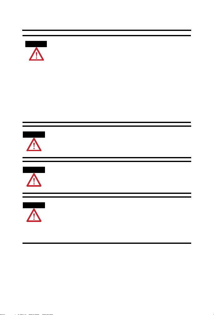
Identifies information about practices or circumstances that can cause an explosion
in a hazardous environment, which may lead to personal injury or death, property
damage, or economic loss.
Identifies information that is critical for successful application and understanding of
the product.
) describes some important differences between solid state
Publication
Identifies information about practices or circumstances that can lead to personal
injury or death, property damage, or economic loss. Attentions help you identify a
hazard, avoid a hazard and recognize the consequences.
Labels may be on or inside the equipment (for example, drive or motor) to alert
people that dangerous voltage may be present.
Labels may be on or inside the equipment (for example, drive or motor) to alert
people that surfaces may reach dangerous temperatures.
1799-IN013B-EN-P - May 2013
Page 3

Embedded I/O Expansion Board with 10 Outputs 3
ATTENTION
Environment and Enclosure
This equipment is intended for use in a Pollution Degree 2 industrial
environment, in overvoltage Category II applications (as defined in IEC
60664-1), at altitudes up to 2000 m (6562 ft) without derating.
This equipment is considered Group 1, Class A industrial equipment
according to IEC/CISPR 11. Without appropriate precautions, there may be
difficulties with electromagnetic compatibility in residential and other
environments due to conducted and radiated disturbances.
This equipment is supplied as open-type equipment. It must be mounted
within an enclosure that is suitably designed for those specific environmental
conditions that will be present and appropriately designed to prevent
personal injury resulting from accessibility to live parts. The enclosure must
have suitable flame-retardant properties to prevent or minimize the spread of
flame, complying with a flame spread rating of 5VA, V2, V1, V0 (or equivalent)
if non-metallic. The interior of the enclosure must be accessible only by the
use of a tool. Subsequent sections of this publication may contain additional
information regarding specific enclosure type ratings that are required to
comply with certain product safety certifications.
In addition to this publication, see:
• Industrial Automation Wiring and Grounding Guidelines, Rockwell
Automation publication 1770-4.1
requirements.
., for additional installation
• NEMA Standard 250 and IEC 60529, as applicable, for explanations of
the degrees of protection provided by different types of enclosure.
Publication 1799-IN013B-EN-P - May 2013
Page 4
4 Embedded I/O Expansion Board with 10 Outputs
ATTENTION
ATTENTION
ATTENTION
ATTENTION
Preventing Electrostatic Discharge
This equipment is sensitive to electrostatic discharge, which can cause
internal damage and affect normal operation. Follow these guidelines when
you handle this equipment:
• Touch a grounded object to discharge potential static.
• Wear an approved grounding wriststrap.
• Do not touch connectors or pins on component boards.
• Do not touch circuit components inside the equipment.
• Use a static-safe workstation, if available.
• Store the equipment in appropriate static-safe packaging when not in
use.
Do not wire more than 2 conductors on any single terminal.
To comply with the CE Low Voltage Directive (LVD), this equipment and all
connected I/O must be powered from a source compliant with the following:
Safety Extra Low Voltage (SELV) or Protected Extra Low Voltage (PELV).
To comply with UL restrictions, this equipment and all connected I/O must be
powered from a source compliant with the following:
10…30V DC Class 2 Power Supply or a 10…30V DC UL Listed or Recognized
Power Supply with isolated outputs limited to 200 volt-amperes in each
ungrounded output line. This equipment and its power source must be
mounted in a suitable enclosure with proper spacings maintained.
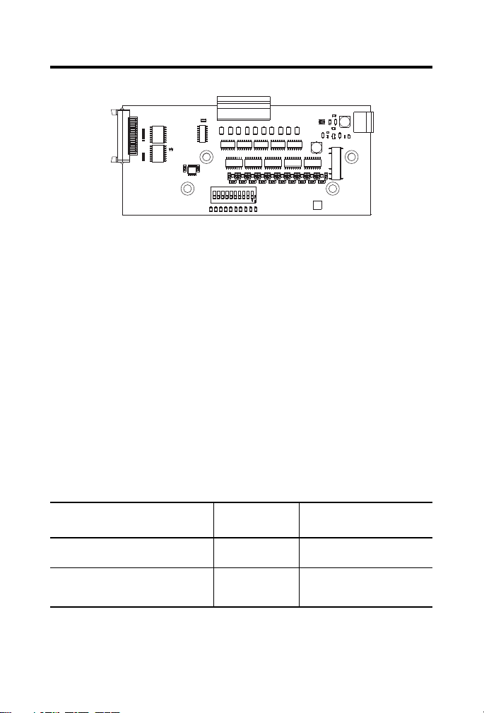
About the Board
The 1799-OQ10X is an expansion 10-point Output board that works only with
1799ER-IQ10XOQ10 as an expansion I/O module.
This board has 10 outputs, that are self-protected 24V DC sinking or sourcing.
Publication
1799-IN013B-EN-P - May 2013
Page 5
Embedded I/O Expansion Board with 10 Outputs 5
45076
Parts List
Your package contains:
• one 1799-OQ10X board.
• ribbon expansion cable
• four stand-off rods
• four countersunk screws
• four roundhead screws
• these installation instructions.
Required Hardware
All mating connectors must be ordered separately. This table identifies the
different connector and hardware options.
Option Catalog Number Third-party Supplier &
Part Number
2, 12-position, gold-plated I/O mating
connectors
2-position plug for auxiliary power 1799-AUXCON Phoenix Contact, Part number
1799-12SPCON Phoenix - FK-MC 0.5/12-ST-2.5AU
- 1923432
MSTB2.5/2-ST-5.08 BK/AU -
1765551)
Publication 1799-IN013B-EN-P - May 2013
Page 6

6 Embedded I/O Expansion Board with 10 Outputs
Install the Board
To install the board:
• mount the board (on 1799ER-IQ10XOQ10).
• connect the board (Auxiliary Power, I/O, ribbon expansion cable).
More detailed information about each of these steps is in the following
procedures.
Mount the Board
You can mount the board to the main board, 1799ER-IQ10XOQ10 using
stand-off rods.
1. Place the four stand-offs onto the mounting screws and tighten them.
2. Place the screws through the expansion board into the stand-offs and
tighten them.
Publication
1799-IN013B-EN-P - May 2013
Page 7

Embedded I/O Expansion Board with 10 Outputs 7
IMPORTANT
or
45074
DIN Rail Bracket
DIN Rail
or
Mounting
Plate
Stand-off
18 mm
20 mm
3. Connect the expansion board to the base board with the ribbon
expansion cable.
With the addition of the expansion board, the depth of the pair of boards is
approximately 45 mm ( 1.77 in.).
Publication 1799-IN013B-EN-P - May 2013
Page 8

8 Embedded I/O Expansion Board with 10 Outputs
19.1 mm
( 0.75 in )
67.1 mm
( 2.64 in )
87.6 mm
( 3.45 in )
149.9 mm
( 5.90 in )
11.4 mm
( 0.45 in )
11.4 mm
( 0.45 in )
44999
Output Connector (P2)
Expansion
Board
Connector
(P1)
Aux Power (P3 )
45076
Board Dimensions
Connect the Board
Use these illustrations and tables to help you connect the board.
Publication
1799-IN013B-EN-P - May 2013
Page 9

Embedded I/O Expansion Board with 10 Outputs 9
P3 Auxiliary Power
Connector
Pin
Signal
124V DC
2 24V DC Ret
P2 Output Connector
Pin
Signal
1 Output 0
2 Output 1
3 Output 2
4 24V DC Ret
5 Output 3
6 Output 4
7 Output 5
8 Output 6
9 24V DC
10 Output 7
11 Output 8
12 Output 9
These tables identifies the signal for the connectors on the 1799-OQ10X.
Connect the Field Output Device to the I/O Connector (P3)
The 1799-OQ10X board has outputs that supply current to your field output
device (sourcing outputs) or sink current from your field output device (sinking
outputs).
Use these wiring diagrams to connect the outputs on this board.
Publication 1799-IN013B-EN-P - May 2013
Page 10

10 Embedded I/O Expansion Board with 10 Outputs
Outputs (Sourcing)
Return
01224V dc 24V dc345 6 78 9
Outputs (Sinking)
Load
Return
01224V dc 24V dc345 6 78 9
Load
45081
OUT
SOURCE
O N
OUT
SINK
1098
7 6 5 4 3 2
1
45073
Outputs
Each output can be configured via a dip switch for sinking or sourcing output.
Wire each output in accordance with your selected configuration. Default dip
switch settings are at sinking output. Configure the switches before power-up.
Publication
1799-IN013B-EN-P - May 2013
Page 11

Embedded I/O Expansion Board with 10 Outputs 11
I/0 Status Indicators
45075
Auxiliary Status Indicator
Interpret the Status Indicators
This board has the following status indicators.
• Power (1)
• Individual output (10)
Indicator Status
Status Description
Auxiliary
status
Output
status
Off No auxiliary power to device or input not valid.
Green Auxiliary power applied to device.
Off Output not energized.
Yellow Output energized.
Publication 1799-IN013B-EN-P - May 2013
Page 12

12 Embedded I/O Expansion Board with 10 Outputs
Communicate with Your Module
1799-OQ10X + 1799-OQ10X Data Definition (optional)
Instance 161 - Consumed 20 Point Output
Consumed
Byte
0 Out7 Out6 Out5 Out4 Out3 Out2 Out1 Out0
1 Out15 Out14 Out13 Out12 Out11 Out10 Out9 Out8
2 Reserved Out19 Out18 Out17 Out16
3 Reserved
Bit 7 Bit 6 Bit 5 Bit 4 Bit 3 Bit 2 Bit 1 Bit 0
EtherNet/IP Connection with RSLogix 5000
The following instructions are for RSLogix 5000 version 17 or later.
1. Power down and connect the expansion board to base board.
2. Power up the board and obtain the IP address via DHCP.
3. In the General tab, click the Change button.
4. In the Module Definition screen, select 1799-OQ10X 10 Point 24V
DC output for the expansion module.
5. Click the OK button, then click the Apply button.
Publication
1799-IN013B-EN-P - May 2013
Page 13

Embedded I/O Expansion Board with 10 Outputs 13
Specifications
Output
Attribute Valu e
Outputs per block 10 sinking or sourcing, 0.5A, short circuit protected, pilot duty
Output auxiliary voltage 10...30V DC
On-state voltage drop 250 mV max
On-state current 0.5 A max
Off-state leakage 20 μA max
Card current (all outputs
on)
Surge current - for
10ms, repeatable Every
2 s (individual outputs)
General
Attribute Value
Auxiliary power voltage
range
Auxiliary power current
outputs on
Auxiliary power current
outputs off
Voltage rating Vi = 24V DC, Ii = 4A, Vout = 30V DC, Iout = 0.5A, Isurge=1A
Dimensions (H x W x D),
approx.
Weight, approx. 0.10 kg (0.22 lb)
Enclosure type rating None (open-style)
Pilot duty rating NEMA DC-14
Isolation voltage 50V (continuous), Basic Insulation Type, Outputs to System
4.0 A max
1.0 A
24V DC nominal (10...30V DC)
4 A max
36 mA
67.1 x 149.9 x 18 mm (2.64 x 5.97 x 0.71 in.)
No isolation between individual Outputs, and Outputs to I/O (Aux) Power
Type tested at 750V DC for 60 s.
Publication 1799-IN013B-EN-P - May 2013
Page 14

14 Embedded I/O Expansion Board with 10 Outputs
General
Attribute Value
Power dissipation 1.12W @ 30V DC Auxiliary Power In
I/O and auxiliary power
wire size
Wiring category
(1)
Use this Conductor Category information for planning conductor routing. Refer to publication 1770-4.1,
Industrial Automation Wiring and Grounding Guidelines.
(1)
I/O:
0.13...0.5 mm² (26...20 AWG) solid or stranded copper wire rated at 75 oC
(167 °F) or greater. 1.2 mm (3/64 in.) insulation max.
Auxiliary power:
0.80...2.5 mm² (18...14 AWG) solid or stranded copper wire rated at 75 oC
(167 °F) or greater. 1.2 mm (3/64 in.) insulation max.
2 - on signal ports
2 - on power ports
Environmental Specifications
Attribute Value
Temperature,
operating
Temperature,
storage
Relative humidity IEC 60068-2-30 (Test Db, Unpackaged Damp Heat):
Vibration IEC60068-2-6 (Test Fc, Operating):
Shock, operating IEC60068-2-27 (Test Ea, Unpackaged Shock):
Shock,
non-operating
Emissions CISPR 11:
IEC 60068-2-1 (Test Ad, Operating Cold),
IEC 60068-2-2 (Test Bd, Operating Dry Heat),
IEC 60068-2-14 (Test Nb, Operating Thermal Shock):
-20…70 °C (-4…158 °F)
IEC 60068-2-1 (Test Ab, Unpackaged Non-operating Cold),
IEC 60068-2-2 (Test Bb, Unpackaged Non-operating Dry Heat),
IEC 60068-2-14 (Test Na, Unpackaged Non-operating Thermal Shock):
-40…85 °C (-40…185 °F)
5…95% non-condensing
2 g @ 10…500 Hz
30 g
IEC60068-2-27 (Test Ea, Unpackaged Shock):
50 g
Group 1, Class A
Publication
1799-IN013B-EN-P - May 2013
Page 15

Embedded I/O Expansion Board with 10 Outputs 15
Environmental Specifications
Attribute Value
ESD immunity IEC 61000-4-2:
Radiated RF
immunity
EFT/B immunity IEC 61000-4-4:
Surge transient
immunity
Conducted RF
immunity
6 kV contact discharges
8 kV air discharges
IEC 61000-4-3:
10V/m with 1 kHz sine-wave 80% AM from 80…2000 MHz
10V/m with 200 Hz 50% Pulse 100% AM at 900 MHz
10V/m with 200 Hz 50% Pulse 100% AM at 1890 MHz
10V/m with 1 kHz sine-wave 80% AM from 2000…2700 MHz
±2 kV at 5 kHz on power ports
±2 kV at 5 kHz on signal ports
IEC 61000-4-5:
±1 kV line-line(DM) and ±2 kV line-earth(CM) on power ports
±1 kV line-line(DM) and ±2 kV line-earth(CM) on signal ports
IEC 61000-4-6:
10V rms with 1 kHz sine-wave 80% AM from 150 kHz…80 MHz
Certifications (when product is marked)
(1)
Attribute Valu e
c-UR-us UL Recognized Component Industrial Control Equipment, certified for US and
CE European Union 2004/108/EC EMC Directive, compliant with:
C-Tick Australian Radiocommunications Act, compliant with:
(1)
See the Product Certification link at http://www.ab.com for Declarations of Conformity, Certificates,
and other certification details.
Canada. See UL File E322657.
EN 61326-1; Meas./Control/Lab., Industrial Requirements
EN 61000-6-2; Industrial Immunity
EN 61000-6-4; Industrial Emissions
EN 61131-2; Programmable Controllers (Clause 8, Zone A & B)
AS/NZS CISPR 11; Industrial Emissions
Publication 1799-IN013B-EN-P - May 2013
Page 16

Rockwell Automation Support
Rockwell Automation provides technical information on the Web to assist you in using its
products. At http://support.rockwellautomation.com
, you can find technical manuals, a
knowledge base of FAQs, technical and application notes, sample code and links to
software service packs, and a MySupport feature that you can customize to make the best
use of these tools.
For an additional level of technical phone support for installation, configuration, and
troubleshooting, we offer TechConnect support programs. For more information, contact
your local distributor or Rockwell Automation representative, or visit
http://support.rockwellautomation.com
.
Installation Assistance
If you experience a problem within the first 24 hours of installation, please review the
information that's contained in this manual. You can also contact a special Customer
Support number for initial help in getting your product up and running.
United States 1.440.646.3434
Outside United States Please contact your local Rockwell Automation representative for any
Monday – Friday, 8 a.m. – 5 p.m. EST
technical support issues.
New Product Satisfaction Return
Rockwell Automation tests all of its products to ensure that they are fully operational
when shipped from the manufacturing facility. However, if your product is not
functioning and needs to be returned, follow these procedures.
United States Contact your distributor. You must provide a Customer Support case number
Outside United States Please contact your local Rockwell Automation representative for the return
Allen-Bradley, TechConnect, RSLogix 5000, and Rockwell Automation are trademarks of Rockwell Automation, Inc.
Trademarks not belonging to Rockwell Automation are property of their respective companies.
(see phone number above to obtain one) to your distributor in order to
complete the return process.
procedure.
Publication 1799-IN013B-EN-P - May 2013 PN-204014
Supersedes Publication 1799-IN013A-EN-P - March 2010 Copyright © 2013 Rockwell Automation, Inc. All rights reserved. Printed in the U.S.A.
 Loading...