

Page 1
Installation Instructions
16 Input/16 Output Digital and 2 Input/2 Output
Analog Embedded I/O Boards
Catalog Numbers 1799-D16U16VAGL,
1799-D16U16BAGL
Topic Page
Important User Information 2
Environment and Enclosure 3
About the Board 3
Install the Board 4
Set the Node Address 5
Mount the Board 6
Connect the Board 8
Configure the Parameters 17
Calibrate Your Analog Inputs and Outputs 19
Troubleshoot the I/O Boards 26
Specifications 28
About This Publication
This publication provides information on the selection, installation, configuring and
troubleshooting the 36-point I/O boards.
Publication 1799-IN011A-EN-P - February 2007
Page 2
2 16 Input/16 Output Digital and 2 Input/2 Output Analog Embedded I/O Boards
Important User Information
Solid state equipment has operational characteristics differing from those of electromechanical equipment.
Safety Guidelines for the Application, Installation and Maintenance of Solid State Controls (Publication
SGI-1.1 available from your local Rockwell Automation sales office or online at
http://www.literature.rockwellautomation.com
equipment and hard-wired electromechanical devices. Because of this difference, and also because of the
wide variety of uses for solid state equipment, all persons responsible for applying this equipment must
satisfy themselves that each intended application of this equipment is acceptable.
In no event will Rockwell Automation, Inc. be responsible or liable for indirect or consequential damages
resulting from the use or application of this equipment.
The examples and diagrams in this manual are included solely for illustrative purposes. Because of the many
variables and requirements associated with any particular installation, Rockwell Automation, Inc. cannot
assume responsibility or liability for actual use based on the examples and diagrams.
No patent liability is assumed by Rockwell Automation, Inc. with respect to use of information, circuits,
equipment, or software described in this manual.
Reproduction of the contents of this manual, in whole or in part, without written permission of Rockwell
Automation, Inc., is prohibited.
Throughout this manual, when necessary, we use notes to make you aware of safety considerations.
) describes some important differences between solid state
WARNING
IMPORTANT
ATTENTION
SHOCK HAZARD
BURN HAZARD
Identifies information about practices or circumstances that can cause an explosion in
a hazardous environment, which may lead to personal injury or death, property
damage, or economic loss.
Identifies information that is critical for successful application and understanding of
the product.
Identifies information about practices or circumstances that can lead to personal injury
or death, property damage, or economic loss. Attentions help you identify a hazard,
avoid a hazard and recognize the consequences.
Labels may be on or inside the equipment (for example, drive or motor) to alert people
that dangerous voltage may be present.
Labels may be on or inside the equipment (for example, drive or motor) to alert people
that surfaces may reach dangerous temperatures.
Publication 1799-IN011A-EN-P - February 2007
Page 3
16 Input/16 Output Digital and 2 Input/2 Output Analog Embedded I/O Boards 3
Environment and Enclosure
ATTENTION
This equipment is intended for use in a Pollution Degree 2 industrial environment, in
overvoltage Category II applications (as defined in IEC publication 60664-1), at altitudes
up to 2000 m (6562 ft.) without derating.
This equipment is considered Group 1, Class A industrial equipment according to
IEC/CISPR Publication 11. Without appropriate precautions, there may be potential
difficulties ensuring electromagnetic compatibility in other environments due to
conducted as well as radiated disturbance.
This equipment is supplied as open type equipment. It must be mounted within an
enclosure that is suitably designed for those specific environmental conditions that will
be present and appropriately designed to prevent personal injury resulting from
accessibility to live parts. The interior of the enclosure must be accessible only by the use
of a tool. The enclosure must have suitable flame-retardant properties to prevent or
minimize the spread of flame, complying with a flame spread rating of 5VA, V2, V1, V0 (or
equivalent) if nonmetallic. Subsequent sections of this publication may contain additional
information regarding specific enclosure type ratings that are required to comply with
certain product safety certifications.
In addition to this publication, see:
• Industrial Automation Wiring and Grounding Guidelines, Allen-Bradley publication
1770-4.1, for additional installation requirements.
• NEMA Standards publication 250 and IEC publication 60529, as applicable, for
explanations of the degrees of protection provided by different types of enclosure.
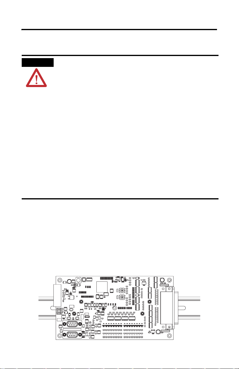
About the Board
The board is a 36-point I/O board that communicates via a DeviceNet network.
This board has 16 digital inputs, 16 digital outputs, 2 analog inputs, and 2 analog outputs.
Inputs are 24V dc sourcing or sinking. Digital outputs are self-protected 24V dc sourcing
(1799-D16U16BAGL) or sinking (1799-D16U16VAGL). Analog outputs support both
current and voltage outputs.
42557
Publication 1799-IN011A-EN-P - February 2007
Page 4
4 16 Input/16 Output Digital and 2 Input/2 Output Analog Embedded I/O Boards
Parts List
Your package contains:
• one 1799 I/O board.
• installation instructions.
Optional Hardware
All mating connectors and mounting hardware must be ordered separately. The following
table identifies the different connector and hardware options.
Option Catalog Number Third Party Supplier & Part Number
2 DIN rail brackets (4 screws) 1799-BRKD N/A
5-position, open-style plug for
DeviceNet network (2 locking screws)
50-pin, D-sub I/O mating connector solder cup
50-pin, D-sub I/O mating connector header and crimp pins
9-pin, D-sub I/O mating connector solder cup
9-pin, D-sub I/O mating connector header and crimp pins
1799-DNETSCON DeviceNet Buyer’s Guide at
http://www.odva.org
1799-DSSCON Amphenol Corp. - 777DF-D50P
ITT Cannon - DDM50PK127
1799-DSCCON Tyco Electronics - 205212-1 (header)
Tyco Electronics - 66506-4 (pins)
EBY Co. - DR50-P02-0S (header only)
1799-DSS9CON Tyco Electronics - 747904-5
1799-DSC9CON Tyco Electronics - 6-66506-1
Install the Board
To install the board do the following:
• Set the node address.
• Mount the board (brackets or mounting screws).
• Connect the board (DeviceNet network, I/O).
• Connect the board (power).
• Communicate with your board.
• Configure the parameters.
More detailed information about each of these steps is included in the following procedures.
Publication 1799-IN011A-EN-P - February 2007
Page 5
16 Input/16 Output Digital and 2 Input/2 Output Analog Embedded I/O Boards 5
ATTENTION
Prevent Electrostatic Discharge
This equipment is sensitive to electrostatic discharge, which can cause internal damage
and affect normal operation. Follow these guidelines when you handle this equipment:
• Touch a grounded object to discharge potential static.
• Wear an approved grounding wriststrap.
• Do not touch connectors or pins on component boards.
• Do not touch circuit components inside the equipment.
• Use a static-safe workstation, if available.
• Store the equipment in appropriate static-safe packaging when not in use.
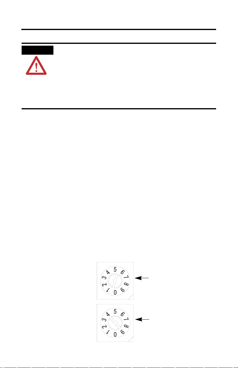
Set the Node Address
Valid node addresses are 00…63.
Set the node address using the rotary switches or a DeviceNet configuration tool such as
RSNetWorx for DeviceNet software. Setting the switches between 64 and 99 lets the software
have address control.
Each board is shipped with the node address set to 63 in the board’s memory. The rotary
switches are set for position 99 at shipment. The switches are located near the center of the
board. The two switches are:
• MSD (most significant digit).
• LSD (least significant digit).
To reset the node address, use a small blade screwdriver to rotate the switches. Line up the
small arrow on the switch with the number setting you wish to use.
The rotary switches are only read when you apply power to the board. Settings between 64
and 99 cause the board to use the last valid node address stored in the board’s memory.
For example, the last setting in memory is 40. If a change is made to 68, and then you apply
power to the board, the address will default to 40.
LSD (S2)
The LSD (S2)
and MSD (S1)
switches are
shown in the
63 position.
MSD (S1)
42558
Publication 1799-IN011A-EN-P - February 2007
Page 6
6 16 Input/16 Output Digital and 2 Input/2 Output Analog Embedded I/O Boards
The board is equipped with AutoBaud detect. AutoBaud lets the board detect the
communication rate on your DeviceNet network and automatically adjusts to that rate.
The board is shipped with AutoBaud enabled.
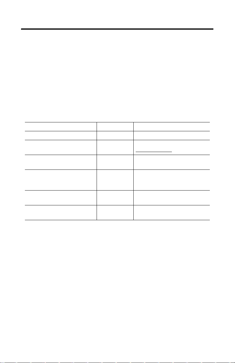
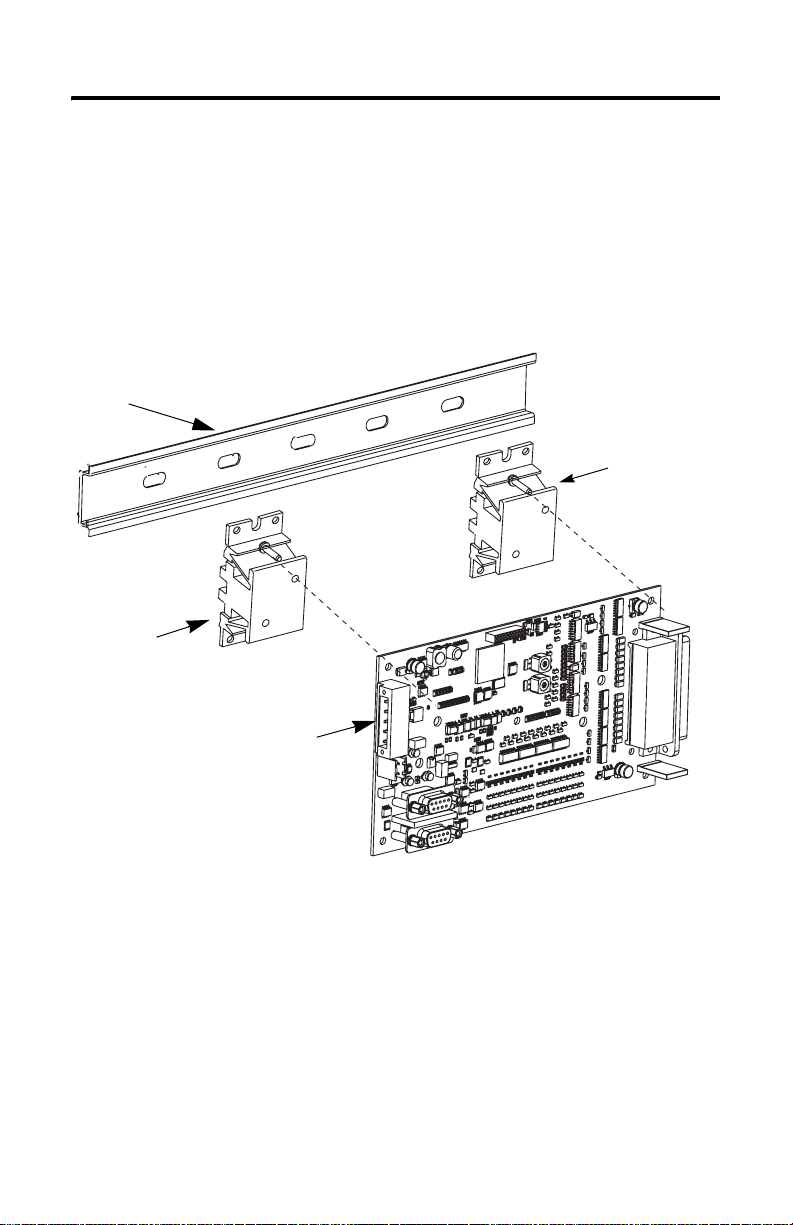
Mount the Board
You can mount the board to a DIN rail using DIN-rail brackets (1799-BRKD) or to a
mounting plate.
DIN Rail
DIN-rail Bracket
DIN-rail Bracket
Circuit Board
42559LC
You can also mount the board in an enclosure with pre-tapped holes, which accommodate
M3 x 0.5 mm screws.
Publication 1799-IN011A-EN-P - February 2007
Page 7
16 Input/16 Output Digital and 2 Input/2 Output Analog Embedded I/O Boards 7
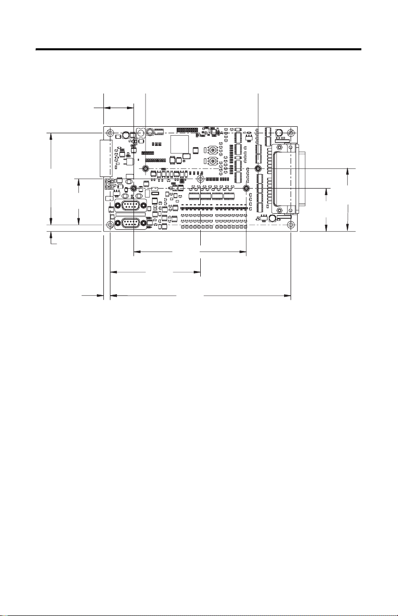
Board Dimensions
29.21
(1.15)
88.90
(3.50)
44.45
(1.75)
41.66
(1.64)
60.71
(2.39)
6.35
(0.25)
6.35
(0.25)
87.63
(3.45)
109.22
(4.30)
175.26
(6.90)
Publication 1799-IN011A-EN-P - February 2007
Page 8
8 16 Input/16 Output Digital and 2 Input/2 Output Analog Embedded I/O Boards
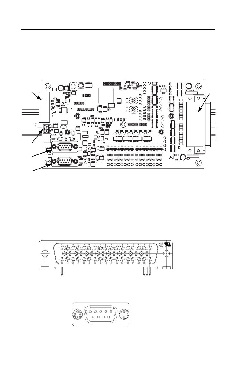
Connect the Board
Use the following pictures and tables to help you connect the DeviceNet connectors and I/O
connectors to the board.
P1
P8
P7
P6
P1 = DeviceNet Connector
42561A
P5 = I/O Connector
P6 = Analog I/O Connector
P7 = Analog I/O Connector
P8 = Analog Power Connector
The following illustration shows the pin number assignments of the digital I/O connector
(P5).
P5
This illustration shows the analog connectors, P6 and P7.
5
9
1
4
3
2
6
7
8
Publication 1799-IN011A-EN-P - February 2007
42606
Page 9
16 Input/16 Output Digital and 2 Input/2 Output Analog Embedded I/O Boards 9
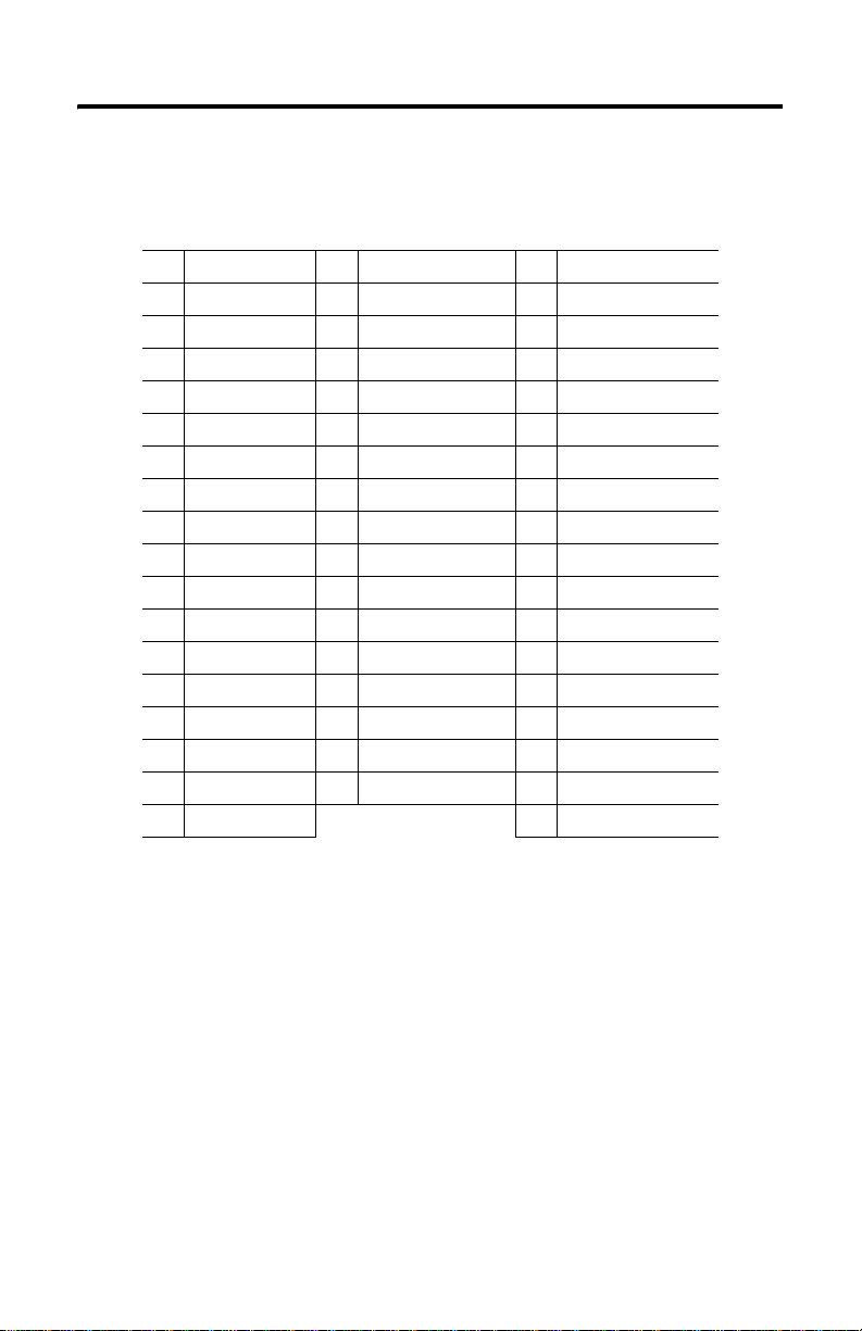
The following table identifies the signal for each 1799-D16U16BAGL pin number on the I/O
connector.
P5 1799-D16U16BAGL I/O Connector
Pin Signal Pin Signal Pin Signal
1 Output 15 18 Output 13 34 Output 12
2 Output 9 19 Output 8 35 Output 14
3 Output 11 20 Output 10 36 GRP 1 Return
4 +24V dc-GRP 1 21 Input 1 37 Input 0
5 +24V dc-GRP 1 22 Common In GRP 0 38 Input 2
6 Input 3 23 Input 6 39 Input 4
7 Input 5 24 GRP 1 Return 40 Input 7
8 GRP 0 Return 25 Input 11 41 Input 10
9 Output 4 26 Input 9 42 Input 8
10 +24V dc-GRP 0 27 Input 14 43 Common In GRP 1
11 Output 5 28 Input 12 44 Input 13
12 Output 7 29 Output 6 45 Input 15
13 Output 0 30 GRP 0 Return 46 Not Used
14 Output 1 31 Not Used 47 Not Used
15 +24V dc-GRP 0 32 Not Used 48 Not Used
16 Output 2 33 Not Used 49 Not Used
17 Output 3 50 Not Used
Publication 1799-IN011A-EN-P - February 2007
Page 10
10 16 Input/16 Output Digital and 2 Input/2 Output Analog Embedded I/O Boards
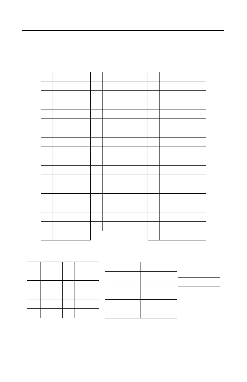
The following table identifies the signal for each 1799-D16U16VAGL pin number on the I/O
connector.
P5 1799-D16U16VAGL I/O Connector
Pin Signal Pin Signal Pin Signal
1 Output 15 18 Output 13 34 Output 12
2 Output 9 19 Output 8 35 Output 14
3 Output 11 20 Output 10 36 GRP 1 Return
4 +24V dc-GRP 1 21 Input 1 37 Input 0
5 +24V dc-GRP 1 22 Common In GRP 0 38 Input 2
6 Input 3 23 Input 6 39 Input 4
7 Input 5 24 GRP 1 Return 40 Input 7
8 GRP 0 Return 25 Input 11 41 Input 10
9 Output 4 26 Input 9 42 Input 8
10 +24V dc-GRP 0 27 Input 14 43 Common In GRP 1
11 Output 5 28 Input 12 44 Input 13
12 Output 7 29 Output 6 45 Input 15
13 Output 0 30 GRP 0 Return 46 Not Used
14 Output 1 31 Not Used 47 Not Used
15 +24V dc-GRP 0 32 Not Used 48 Not Used
16 Output 2 33 Not Used 49 Not Used
17 Output 3 50 Not Used
P6 Analog I/O Connector
Signal
Pin
1
2
3
4
5
V_Out 0
NC
V_In 0
A_24V
AGND
Pin Signal
6 C_Out 0
7NC
8 C_In 0
9
P7 Analog I/O Connector
Pin
1
2
3
4
5
Publication 1799-IN011A-EN-P - February 2007
Signal
V_Out 1
NC
V_In 1
A_24V
AGND
Pin Signal
6 C_Out 1
7NC
8 C_In 1
9NC
P8 Analog Power
Connector
Signal
Pin
24V
1
AGND
2
Page 11

16 Input/16 Output Digital and 2 Input/2 Output Analog Embedded I/O Boards 11
The DeviceNet wire insulation colors are shown below.
P1 DeviceNet Connector
Pin Insulation Colors
1Black
2Blue
3Shield
4White
5Red
Auxiliary Power Specifications
The power source used to supply the auxiliary power to the outputs and analog circuitry must
meet the following:
ATTENTION
ATTENTION
To comply with the CE Low Voltage Directive (LVD), all connections to this equipment must be
powered from a source compliant with the following:
Safety Extra Low Voltage (SELV) or Protected Extra Low Voltage (PELV) with isolated outputs
limited to 200
To comply with UL restrictions, this equipment must be powered from a source compliant
with the following:
Class 2 or UL Listed /Recognized Power Supply with isolated outputs limited to
200 volt-amperes in each ungrounded output line. This condition requires that
the board and power source be mounted in a suitable ultimate enclosure with
proper spacings maintained.
volt-amperes in each ungrounded output line.
These conditions requires that the board and power source be mounted in a suitable,
ultimate enclosure with proper spacings maintained.
ATTENTION
Do not wire more than 2 conductors on any single terminal.
Publication 1799-IN011A-EN-P - February 2007
Page 12

12 16 Input/16 Output Digital and 2 Input/2 Output Analog Embedded I/O Boards
Connect the Field Output Device to the I/O Connector (P5)
The 1799-D16U16BAGL boards have outputs that supply current to your field output device
(sourcing outputs).
The outputs on these boards are isolated in two groups of eight, with each group requiring
24V dc power and 24V dc ground. Outputs 0…7 are powered from +24V GRP 0 and return
power via GRP 0 Return. Outputs 8…15 are powered from +24V GRP 1 and return power
via GRP 1 Return.
Use the following wiring diagrams to connect both groups of outputs on these boards.
1799-D16U16BAGL Outputs (Sourcing)
GRP 1
Pins 4, 5
+24V
GRP 1
+
+
_
_
Pins 1-3,
18-20, 34, 35
Output X
Load
Load
42563
Pin 8,30
GRP 0
Return
GRP 0
Pins 10, 15
+24V
GRP 0
+
_
Pins 9, 11-14,
16, 17, 29
Output X
Load
Pin 24, 36
GRP 1
Return
The 1799-D16U16VAGL board has outputs that receive current from your field output
device (sinking outputs). The outputs on these boards are in two groups of eight, with each
group requiring 24V dc power and 24V dc ground. Outputs must be from a single 200 VA
supply powered from +24V GRP and return power via GRP Return.
1799-D16U16VAGL Outputs (Sinking)
GRP 0 GRP 1
Pin 8,
30
GRP
Return
Pins 9, 11-14,
16, 17, 29
Output X
Pins 10, 15
+24V
GRP
Pin 24,
36
GRP
Return
Pins 1-3,
18-20, 34, 35
Output X
Pins 4, 5
+24V
GRP
Load
+
_
Publication 1799-IN011A-EN-P - February 2007
Load
+
_
42564
Page 13

16 Input/16 Output Digital and 2 Input/2 Output Analog Embedded I/O Boards 13
Connect the Field Input Device to the I/O Connector (P5)
The inputs on these boards are isolated in two groups of eight, with each group providing a
separate common signal. Inputs 0…7 share the common in GRP 0 signal. Inputs 8…15 share
the common in GRP 1 signal.
The 1799-D16U16BAGL and 1799-D16U16VAGL boards have universal inputs that allow
operation with either sourcing or sinking input devices. The universal feature lets you
configure the inputs as either sinking or sourcing. Use the following wiring diagrams to
connect each group of inputs on the boards.
IMPORTANT
Inputs (Sinking)
Inputs (Sourcing)
All field input devices in each group of eight must be of the same type,
either sinking or sourcing. The board will not operate if the types are
mixed.
GRP 1
Pin 43
Common In
GRP 1
42565
GRP 1
Pins 25-28,
41, 42, 44, 45
Input X
+
_
Pin 22
Common In
GRP 0
GRP 0
Pins 6, 7, 21,
23, 37-40
Input X
GRP 0
Pin 22
Common In
GRP 0
Pins 6, 7, 21,
23, 37-40
Input X
Pins 25-28,
41, 42, 44, 45
Input X
+
_
Pin 43
Common In
GRP 1
+
_
+
_
42566
Publication 1799-IN011A-EN-P - February 2007
Page 14

14 16 Input/16 Output Digital and 2 Input/2 Output Analog Embedded I/O Boards
Communicate With Your Board
This board exchanges I/O with the master on the DeviceNet network through a cyclic,
polled, or change-of-state connection.
The 1799-D16U16BAGL board consumes and produces I/O data as follows.
I/O Connection Type Consumes Produces
Cyclic 6 Bytes 11 Bytes
Polled 6 Bytes 11 Bytes
Change-of-state 6 Bytes 11 Bytes
The 1799-D16U16VAGL board consumes and produces I/O data as follows.
I/O Connection Type Consumes Produces
Cyclic 6 Bytes 11 Bytes
Polled 6 Bytes 11 Bytes
Change-of-state 6 Bytes 11 Bytes
Cyclic — the board produces and consume its I/O cyclically at the rate configured by the
master on the DeviceNet network.
Polled — the master initiates communication by sending its polled I/O message to the board.
The board consumes the message, updates any outputs, and produces a response containing
the input data.
Change-of-state — a production occurs when an input changes. A heartbeat production
occurs if no input condition change occurs within the expected packet rate. This heartbeat
production tells the master that the board is ready to communicate. Consumption occurs
when data changes and the master produces new output data to the board.
Publication 1799-IN011A-EN-P - February 2007
Page 15

16 Input/16 Output Digital and 2 Input/2 Output Analog Embedded I/O Boards 15
Word and bit definitions for the 1799-D16U16BAGL board are shown below.
1799-D16U16BAGL Board Word and Bit Definitions:
Produced Byte Bit 7 Bit 6 Bit 5 Bit 4 Bit 3 Bit 2 Bit 1 Bit 0
0 In8 In7 In6 In5 In4 In3 In2 In1
1 In16 In15 In14 In13 In12 In11 In10 In9
2 Rsvd Logic En Rsvd Rsvd OW1 OW0 OFLT 1 OFLT 0
3 Analog Input Channel 0 (LSB)
4 Analog Input Channel 0 (MSB)
5 Analog Input Channel 1 (LSB)
6 Analog Input Channel 1 (MSB)
7 ORI0 URI0 HHAI0 LLAI0 HAI0 LAI0 CMI0 STI0
8 ORI1 URI1 HHAI1 LLAI1 HAI1 LAI1 CMI1 STI1
9 Reserved HCO0 LCO0 CMO0 STO0
10 Reserved HCO1 LCO1 CMO1 STO1
Consumed Byte Bit 7 Bit 6 Bit 5 Bit 4 Bit 3 Bit 2 Bit 1 Bit 0
0 O8 O7 O6 O5 O4 O3 O2 O1
1 O16 O15 O14 O13 O12 O11 O10 O9
2 Analog Output Channel 0 Data (LSB)
3 Analog Output Channel 0 Data (MSB)
4 Analog Output Channel 1 Data (LSB)
5 Analog Output Channel 1 Data (MSB)
Where: I = Digital input
O = Digital output
AI = Analog Input Channel (channel 0 = AI0; channel 1 = AI1)
AO = Analog Output Channel (channel 0 = AO0; channel 1 = AO1)
ST = Analog Input Channel Status (channel 0 = ST0; channel 1 = ST1) (0 = no error; 1 = fault)
CM = Calibration mode (0 = run; 1 = calibration mode)
LA = Low alarm (0 = no error; 1 = fault)
HA = High alarm (0 = no error; 1 = fault)
LLA = Low low alarm (0 = no error; 1 = fault)
HHA = High high alarm (0 = no error; 1 = fault)
UR = Underrange (0 = no error; 1 = fault)
OR = Overrange (0 = no error; 1 = fault)
LC = Low clamp (0 = no error; 1 = fault)
HC = High clamp (0 = no error; 1 = fault)
OW = Analog output open wire (OW0 = channel 0; OW1 = channel 1)
OFLT = Output fault on one or more outputs in a group (OFLT0 = group 0; OFLT1 = group 1)
Rsvd = Reserved
Publication 1799-IN011A-EN-P - February 2007
Page 16

16 16 Input/16 Output Digital and 2 Input/2 Output Analog Embedded I/O Boards
Word and bit definitions for the 1799-D16U16VAGL board are shown below.
Word and Bit Definitions for the 1799-D16U16VAGL Board
Produced Byte Bit 7 Bit 6 Bit 5 Bit 4 Bit 3 Bit 2 Bit 1 Bit 0
0 In8 In7 In6 In5 In4 In3 In2 In1
1 In16 In15 In14 In13 In12 In11 In10 In9
2 Rsvd Logic En Rsvd Rsvd OW1 OW0 OFLT 1 OFLT 0
3 Analog Input Channel 0 (LSB)
4 Analog Input Channel 0 (MSB)
5 Analog Input Channel 1 (LSB)
6 Analog Input Channel 1 (MSB)
7 ORI0 URI0 HHAI0 LLAI0 HAI0 LAI0 CMI0 STI0
8 ORI1 URI1 HHAI1 LLAI1 HAI1 LAI1 CMI1 STI1
9 Reserved HCO0 LCO0 CMO0 STO0
10 Reserved HCO1 LCO1 CMO1 STO1
Consumed Byte Bit 7 Bit 6 Bit 5 Bit 4 Bit 3 Bit 2 Bit 1 Bit 0
0 O8 O7 O6 O5 O4 O3 O2 O1
1 O16 O15 O14 O13 O12 O11 O10 O9
2 Analog Output Channel 0 Data (LSB)
3 Analog Output Channel 0 Data (MSB)
4 Analog Output Channel 1 Data (LSB)
5 Analog Output Channel 1 Data (MSB)
Where: I = Digital input
O = Digital output
AI = Analog Input Channel (channel 0 = AI0; channel 1 = AI1)
AO = Analog Output Channel (channel 0 = AO0; channel 1 = AO1)
ST = Analog Input Channel Status (channel 0 = ST0; channel 1 = ST1) (0 = no error; 1 = fault)
CM = Calibration mode (0 = run; 1 = calibration mode)
LA = Low alarm (0 = no error; 1 = fault)
LLA = Low low alarm (0 = no error; 1 = fault)
HA = High alarm (0 = no error; 1 = fault)
HHA = High high alarm (0 = no error; 1 = fault)
UR = Underrange (0 = no error; 1 = fault)
OR = Overrange (0 = no error; 1 = fault)
LC = Low clamp (0 = no error; 1 = fault)
HC = High clamp (0 = no error; 1 = fault)
OW = Analog output open wire (OW0 = channel 0; OW1 = channel 1)
OFLT = Output fault on one or more outputs in a group (OFLT0 = group 0; OFLT1 = group 1)
Rsvd = Reserved
Publication 1799-IN011A-EN-P - February 2007
Page 17

16 Input/16 Output Digital and 2 Input/2 Output Analog Embedded I/O Boards 17
Configure the Parameters
The 1799 I/O boards have parameters that are configurable through a DeviceNet
configuration tool such as RSNetWorx for DeviceNet software. The DeviceNet
configuration tools require an Electronic Data Sheet (EDS) for the 1799 I/O boards to
configure the module’s parameters. Find the EDS files at http://www.odva.org
Use the descriptions in the following table to help you configure the parameters.
Parameter Description
AutoBaud Enables the board to match the network’s communication
rate. When enabled, Baud Rate parameter is ignored.
Input Off-to-On Filter Time Controls the amount of time the input must be in the on
state before the board reports the input as on.
Input On-to-Off Filter Time Controls the amount of time the input must be in the
off-state before the board reports the input as off.
Output Idle State Controls the state of each output when the DeviceNet
master is in an idle-state.
Output Fault State Controls the state of each output when the board loses
communication with the DeviceNet master.
Output Idle Value Controls the value that outputs will have when the output
idle-state is set to use idle value.
Output Fault Value Controls the value that outputs will have when the output
fault-state is set to use fault value.
.
The DeviceLogix capable boards, 1799-D16U16BAGL and 1799-D16U16VAGL, have
additional parameters, which are described in the DeviceLogix User Manual, publication
number ACIG-UM001, and in the Embedded I/O for DeviceNet Technical Data,
publication number 1799-TD001.
Publication 1799-IN011A-EN-P - February 2007
Page 18

18 16 Input/16 Output Digital and 2 Input/2 Output Analog Embedded I/O Boards
Additional Parameters
Parameter Description
AI Low Scaling Analog input low scaling value or low engineering units.
AI High Scaling Analog input high scaling value or high engineering units.
AI Digital Filter Controls digital filter time constant.
AI Alarm (Low/High Low)
Low/High High)
AI Input Range Defines type and range of input signal. Controls way of calibration.
AI Enable Alarm Latch Controls latch of alarm status until a reset latch service is issued.
AI Disable Alarms Controls function of alarm.
AI Notch Filter Controls sample rate of A/D converter.
AI Update Rate Assigns the rate at which the inputs are sampled by firmware.
AO Fault Value Controls output value during communication fault.
AO Idle Value Controls output value during idle or program mode.
AO Low Scaling Analog output low scaling value or low engineering units.
AO High Scaling Analog output high scaling value or high engineering units.
AO Low Clamp The lowest value of the output. If the output value is set below this
AO High Clamp The highest value of the output. If the output value is set above this
AO Output Range Defines type and range of output signal. Controls way of calibration.
AO Fault State Controls the output choices during a communication fault.
AO Idle State Controls the output choices during idle or program mode.
AO Enable Alarm Latch Controls latch of alarm status until a reset latch service is issued.
AO Disable Alarms Controls function of alarm.
Control alarm status when input exceed alarm threshold.
value, the output will be set to the low clamp value.
value, the output will be set to the high clamp value.
Publication 1799-IN011A-EN-P - February 2007
Page 19

16 Input/16 Output Digital and 2 Input/2 Output Analog Embedded I/O Boards 19
Calibrate Your Analog Inputs and Outputs
Follow the example calibrations shown below to learn how to calibrate your card.
Input Calibration
The wiring method decides the operating mode of current or voltage inputs. Calibration data
of both voltage and current are stored in nonvolatile memory and selected according to the
parameter value of AI INPUT RANGE.
Example current calibration of channel 0
Perform the following steps to calibrate your current input.
1. Set input channel range to 0…20 mA.
2. Select the input channel.
3. Send command to Begin Calibration.
Publication 1799-IN011A-EN-P - February 2007
Page 20

20 16 Input/16 Output Digital and 2 Input/2 Output Analog Embedded I/O Boards
4. Apply 4.000 mA ±0.5 μA and allow to settle for a minimum of 200 ms.
TIP
5. Send the Accept Low Calibration command.
6. Apply 20.00 mA ( ±0.5 μA) and allow to settle for a minimum of 200 ms.
7. Send the Accept High Calibration command.
Always apply 4 mA to inputs as low reference when calibrating current
inputs.
8. If both samples were successful the module saves data to Dataflash, recalculates
module parameters and exits calibration automatically.
Calibration can be aborted or restarted at any time. Data is not saved until the end of step 7.
Publication 1799-IN011A-EN-P - February 2007
Page 21

16 Input/16 Output Digital and 2 Input/2 Output Analog Embedded I/O Boards 21
Example voltage calibration of channel 0
1. Set input channel range 0…10V.
2. Select the input channel.
3. Send command to Begin Calibration.
4. Apply 0.000V (±) 500 μV and allow to settle for a minimum of 200 ms.
5. Send the Accept Low Calibration command.
Publication 1799-IN011A-EN-P - February 2007
Page 22

22 16 Input/16 Output Digital and 2 Input/2 Output Analog Embedded I/O Boards
6. Apply 10.000V (±500 μV) and allow to settle for a minimum of 200 ms.
7. Send the Accept High Calibration command.
8. If both samples were successful the module saves data to Dataflash, recalculates
module parameters and exits calibration automatically.
Calibration can be aborted or restarted at any time. Data is not saved until the end of step 7.
Output Calibration
The wiring method decides the operating mode of current or voltage output. Calibration data
of both voltage and current are stored in nonvolatile memory and selected according to
parameter value of AO OUTPUT RANGE.
So select output range of either current or voltage prior to calibration.
Example current calibration of channel 0.
1. Set output channel range to 0…20 mA.
2. Select output channel 0.
Publication 1799-IN011A-EN-P - February 2007
Page 23

16 Input/16 Output Digital and 2 Input/2 Output Analog Embedded I/O Boards 23
3. Apply a 220 Ω (±15%) load resistor to channel 0.
4. Send Begin Calibration command.
5. Send the Output Low Reference command
6. Record the actual output current.
7. Send the Output High Reference command.
8. Record the actual output current.
9. Set parameter values with recorded values.
Publication 1799-IN011A-EN-P - February 2007
Page 24

24 16 Input/16 Output Digital and 2 Input/2 Output Analog Embedded I/O Boards
10. Send the Finish Calibration command.
11. If LED indicators are no longer blinking, calibration is complete.
Calibration can be aborted or restarted at any time. Data is not saved until the end of step 10.
Example voltage calibration of channel 0.
1. Set output channel range to 0…10V.
2. Select output channel 0.
3. Apply a 10 KΩ (± 1%) load resistor to channel 0. (10V output/10 K = 1 mA load)
4. Send Begin Calibration command.
Publication 1799-IN011A-EN-P - February 2007
Page 25

16 Input/16 Output Digital and 2 Input/2 Output Analog Embedded I/O Boards 25
5. Send the Output Low Reference command
6. Record the actual output current.
7. Send the Output High Reference command.
8. Record the actual output voltage.
9. Set parameter values with recorded values.
10. Send the Finish Calibration command.
11. If LED indicators are no longer blinking calibration is complete.
Calibration can be aborted or restarted at any time. Data is not saved until the end of step 10.
Publication 1799-IN011A-EN-P - February 2007
Page 26

26 16 Input/16 Output Digital and 2 Input/2 Output Analog Embedded I/O Boards
Troubleshoot the I/O Boards
This board has the following indicators:
• Board status indicator
• Network status indicator
• Logic status
• Digital I/O state indicators
• Analog I/O state indicators
Status Indicators
DL NSInput LEDs
P1
P8
P7
P6
MS
Analog LEDs Output LEDs
Board Status Indicator (Labeled MS)
Indication Status
None No power
Green Blinking Green Needs commissioning
Solid Green Device operational
Red Blinking Red Minor fault
Solid Red Critical fault
LSD
MSD
P5
42567A
Publication 1799-IN011A-EN-P - February 2007
Page 27

16 Input/16 Output Digital and 2 Input/2 Output Analog Embedded I/O Boards 27
Network Status Indicator (Labeled NS)
Indication Status
None Not on-line
Green Blinking Green On-line/no connections
Solid Green On-line/connected
Red Blinking Red Connection timed out
Solid Red Failed communication: a duplicate node address exists or
module is at the wrong communication rate
DeviceLogix Status Indicator (Labeled DL)
Indication Status
None Logic disabled
Green Solid Green Logic enabled
Blinking Green Local forces applied and local logic enabled
I/O State Indicators (Labeled Inputs and Outputs)
Color Indication Status
None Input or output point off
Yellow Solid Yellow Input or output point on
Analog Input Indicators
Color Indication Status
None No power or calibration started
Green Blinking Green Calibration in process
Solid Green Normal operation
Red Blinking Red Open wire or out of range
Solid Red No AD communications
Analog Output Indicators
Color Indication Status
None No power or calibration started
Green Blinking Green Calibration in progress
Solid Green Normal operation
Red Blinking Red Open wire or out of range
Publication 1799-IN011A-EN-P - February 2007
Page 28

28 16 Input/16 Output Digital and 2 Input/2 Output Analog Embedded I/O Boards
Specifications
16 Input/16 Output Board - Cat. No. 1799-D16U16BAGL and 1799-D16U16VAGL
Attribute Value
Power
DeviceNet voltage range 11…25V dc
DeviceNet current 125 mA
DeviceNet power circuit type Class 2
Digital I/O voltage range 10…30V dc
Digital I/O current max 8 A (all outputs on)
Digital I/O current min 20 mA
Supply power/current ratings Isolated outputs limited to 200 VA in each ungrounded output line
Analog I/O voltage range 10…28.8V dc
Analog I/O current max 200 mA
Analog I/O current min 100 mA
Digital input specifications
Inputs per block 16 sinking or sourcing (2 groups of 8), Type 1 + compatible
Off-state voltage 5V dc
Off-state current 1.5 mA
On-state voltage max 30V dc
On-state voltage min 10V dc
On-state current max 6 mA
On-state current min 2 mA
Digital output specifications
Outputs per block 16 sinking or sourcing, 0.5 A, short-circuit protected, pilot duty
Output voltage range 10…30V dc
Output voltage min 10V dc
Output voltage range nominal 24V dc
Output voltage range max 30V dc
On-state Voltage Drop 250 mV
On-state current 0.5 A max
Off-state leakage 65 μA
Surge current - for 10 ms, repeatable
every 2 s (individual outputs)
1.0 A
Publication 1799-IN011A-EN-P - February 2007
Page 29

16 Input/16 Output Digital and 2 Input/2 Output Analog Embedded I/O Boards 29
Analog input specifications
Voltage, power 10…28.8V
Input current range 0…21 mA
Input resolution 0.32 μA/count (16 bits)
Input voltage range 0…10.5V max; 21 mA max
Current input impedance 238 Ω
Voltage input impedance 190 kΩ
Accuracy current
voltage
Analog output specifications
Output current range 0…21.5 mA
Output voltage range 0…10.5V
Output resolution - current 2.8 μA/count (13 bits)
Output resolution - voltage 180 μV/count
Voltage drive capability 3 mA max
Number of outputs 2 single-ended, nonisolated
Absolute accuracy - current output 0.03%
Absolute accuracy - voltage output 0.06%
Current load on voltage output 21 mA max
Resistive load on current output 790 Ω max
General specifications
Power dissipation 1.8 W max @ 30.0V dc (whole board)
Thermal dissipation 6.14 BTU/hr max @ 30.0V dc (whole board)
Isolation voltage (continuous-voltage
withstand rating)
Wire size - power
Wire size - DeviceNet
Wire size - I/O
Wiring category
(1)
0.012% of FS
0.007% of FS
50V (continuous), Basic Insulation Type, between DeviceNet, I/O,
and I/O power
Tested at 1000V dc for 60 seconds.
No isolation between individual channels
0.80…2.5 mm2 (18...14 AWG) solid or stranded copper wire rated at
°F) or higher, 1.2 mm (3/64 in.) insulation max
75 °C (167
0.25...2.5 mm2 (22...14 AWG) solid or stranded copper wire rated at
°F) or higher (See Publication DNET-UM072)
75 °C (167
0.13...0.5 mm2 (26...20 AWG) solid or stranded copper wire rated at
75 °C (167
°F) or higher, 1.2 mm (3/64 in.) insulation max
2 - on signal ports
2 - on power ports
2 - on communications ports
Publication 1799-IN011A-EN-P - February 2007
Page 30

30 16 Input/16 Output Digital and 2 Input/2 Output Analog Embedded I/O Boards
Enclosure type rating None (open-style)
Pilot Duty Rating
Pilot duty DC-14
LED indicators Board Status indicator - red/green
Network Status indicator - red/green
DeviceLogix Status indicator - green
Input Point indicator - yellow
Output Point indicator - yellow
Dimensions (H x W x D), approx.
millimeters
(inches)
19.05 x 77.85 x 189.33 mm
(0.75 x 3.07 x 7.45 in.)
Weight 0.10 kg (0.22 lb)
(1)
Use this Conductor Category information for planning conductor routing. Refer to Industrial Automation Wiring and
Grounding Guidelines, Publication 1770-4.1.
Environmental Specifications
Attribute Value
Temperature, operating
Temperature, storage
Relative humidity IEC 60068-2-30 (Test Db, Unpackaged Damp Heat):
Vibration IEC 60068-2-6 (Test Fc, Operating):
Shock, operating IEC 60068-2-27 (Test Ea, Unpackaged Shock):
Shock, nonoperating IEC 60068-2-27 (Test Ea, Unpackaged Shock):
Emissions CISPR 11:
ESD immunity IEC 61000-4-2:
Radiated RF immunity IEC 61000-4-3:
IEC 60068-2-1 (Test Ad, Operating Cold),
IIEC 60068-2-2 (Test Bd, Operating Dry Heat),
IEC 60068-2-14 (Test Nb, Operating Thermal Shock):
-20...70 °C (-4...158 °F)
IEC 60068-2-1 (Test Ab, Unpackaged Nonoperating Cold),
IEC 60068-2-2 (Test Bb, Unpackaged Nonoperating Dry Heat),
IEC 60068-2-14 (Test Na, Unpackaged Nonoperating Thermal Shock):
-40...85 °C (-40...185 °F)
5...95% noncondensing
5 g @ 10…500 Hz
30 g
50 g
Group 1, Class A
6 kV indirect contact discharges
10 V/m with 1 kHz sine-wave 80%AM from 80 MHz...2 GHz
1 V/m with 1 kHz sine-wave 80%AM from 2...2.7 GHz
10 V/m with 200 Hz 50% Pulse 100%AM at 900 MHz
10 V/m with 200 Hz 50% Pulse 100%AM at 1890 MHz
Publication 1799-IN011A-EN-P - February 2007
Page 31

16 Input/16 Output Digital and 2 Input/2 Output Analog Embedded I/O Boards 31
EFT/B immunity IEC 61000-4-4
±2 kV at 5 kHz on power ports
±2 kV at 5 kHz on signal ports
±2 kV at 5 kHz on communications ports
Surge transient immunity IEC 61000-4-5:
±1 kV line-line (DM) and ±2 kV line-earth (CM) on power ports
±1 kV line-line (DM) and ±2 kV line-earth (CM) on signal ports
±2 kV line-earth (CM) on communications ports
Conducted RF immunity IEC 61000-4-6:
10V rms with 1 kHz sine-wave 80%AM from 150 kHz...80 MHz
Certifications
Certifications
marked)
C-UR-US UL Recognized Component Industrial Control Equipment, certified for
CE European Union 2004/108/EC EMC Directive, compliant with:
C-Tick Australian Radiocommunications Act, compliant with:
ODVA ODVA conformance tested to DeviceNet specifications
(1)
See the Product Certification link at www.ab.com for Declarations of Conformity, Certificates, and other certification
details.
(1)
(when product is
US and Canada. See UL File E65584.
EN 50082-2; Industrial Immunity
EN 61326; Meas./Control/Lab., Industrial Requirements
EN 61000-6-2; Industrial Immunity
EN 61000-6-4; Industrial Emissions
EN 61131-2; Programmable Controllers (Clause 8, Zone A & B)
AS/NZS CISPR 11; Industrial Emissions
Publication 1799-IN011A-EN-P - February 2007
Page 32

Rockwell Automation Support
Rockwell Automation provides technical information on the Web to assist you in using its
products. At http://support.rockwellautomation.com
knowledge base of FAQs, technical and application notes, sample code and links to software
service packs, and a MySupport feature that you can customize to make the best use of these
tools.
For an additional level of technical phone support for installation, configuration and
troubleshooting, we offer TechConnect Support programs. For more information, contact
your local distributor or Rockwell Automation representative, or visit
http://support.rockwellautomation.com
.
Installation Assistance
If you experience a problem with a hardware module within the first 24 hours of installation,
please review the information that's contained in this manual. You can also contact a special
Customer Support number for initial help in getting your module up and running:
, you can find technical manuals, a
United States 1.440.646.3223
Outside United
States
Monday – Friday, 8am – 5pm EST
Please contact your local Rockwell Automation representative for any
technical support issues.
New Product Satisfaction Return
Rockwell tests all of its products to ensure that they are fully operational when shipped from
the manufacturing facility. However, if your product is not functioning and needs to be
returned:
United States Contact your distributor. You must provide a Customer Support case number
Outside United
States
RSNetWorx for DeviceNet, TechConnect, and DeviceLogix are trademarks of Rockwell Automation, Inc.
Trademarks not belonging to Rockwell Automation are properties of their respective companies.
(see phone number above to obtain one) to your distributor in order to
complete the return process.
Please contact your local Rockwell Automation representative for return
procedure.
Publication 1799-IN011A-EN-P - February 2007 PN 953030-32
Copyright © 2007 Rockwell Automation, Inc. A ll rights reserved. Printed in t he U.S.A.
 Loading...