

Page 1

Installation Instructions
Zone Control I/O Cards
Catalog Numbers 1799-ZCIOB, 1799-D10U10BZC,
1799-ZCIOV, 1799-D10U10VZC
Inside . . .
For See page
Important User Information 2
Environment and Enclosure 3
About the Cards 4
Install the Card 5
Set the Node Address 5
Mount the Card 7
Connect the Card 9
Communicate with the Card 13
Configure the Parameters 14
Troubleshoot the Zone Cards 16
Technical Support 18
Specifications 19
Publication 1799-IN007D-EN-P - October 2005
Page 2
2 Zone Control I/O Cards
Important User Information
Solid state equipment has operational characteristics differing from those of electromechanical equipment.
Safety Guidelines for the Application, Installation and Maintenance of Solid State Controls (Publication
SGI-1.1 available from your local Rockwell Automation sales office or online at
http://www.literature.rockwellautomation.com) describes some important differences between solid state
equipment and hard-wired electromechanical devices. Because of this difference, and also because of the
wide variety of uses for solid state equipment, all persons responsible for applying this equipment must
satisfy themselves that each intended application of this equipment is acceptable.
In no event will Rockwell Automation, Inc. be responsible or liable for indirect or consequential damages
resulting from the use or application of this equipment.
The examples and diagrams in this manual are included solely for illustrative purposes. Because of the many
variables and requirements associated with any particular installation, Rockwell Automation, Inc. cannot
assume responsibility or liability for actual use based on the examples and diagrams.
No patent liability is assumed by Rockwell Automation, Inc. with respect to use of information, circuits,
equipment, or software described in this manual.
Reproduction of the contents of this manual, in whole or in part, without written permission of Rockwell
Automation, Inc., is prohibited.
Throughout this manual, when necessary, we use notes to make you aware of safety considerations.
WARNING
IMPORTANT
ATTENTION
SHOCK HAZARD
BURN HAZARD
Identifies information about practices or circumstances that can cause an explosion in
a hazardous environment, which may lead to personal injury or death, property
damage, or economic loss.
Identifies information that is critical for successful application and understanding of
the product.
Identifies information about practices or circumstances that can lead to personal injury
or death, property damage, or economic loss. Attentions help you identify a hazard,
avoid a hazard and recognize the consequences.
Labels may be located on or inside the equipment (e.g., drive or motor) to alert people
that dangerous voltage may be present.
Labels may be located on or inside the equipment (e.g., drive or motor) to alert people
that surfaces may be dangerous temperatures.
Publication 1799-IN007D-EN-P - October 2005
Page 3

Environment and Enclosure
Zone Control I/O Cards 3
ATTENTION
This equipment is intended for use in a Pollution Degree 2 industrial environment, in
overvoltage Category II applications (as defined in IEC publication 60664-1), at altitudes up to
2000 meters without derating.
This equipment is considered Group 1, Class A industrial equipment according to IEC/CISPR
Publication 11. Without appropriate precautions, there may be potential difficulties ensuring
electromagnetic compatibility in other environments due to conducted as well as radiated
disturbance.
This equipment is supplied as open type equipment. It must be mounted within an enclosure
that is suitably designed for those specific environmental conditions that will be present and
appropriately designed to prevent personal injury resulting from accessibility to live parts. The
interior of the enclosure must be accessible only by the use of a tool. Subsequent sections of
this publication may contain additional information regarding specific enclosure type ratings
that are required to comply with certain product safety certifications.
NOTE: See NEMA Standards publication 250 and IEC publication 60529, as applicable, for
explanations of the degrees of protection provided by different types of enclosure. Also, see
the appropriate sections in this publication, as well as the Allen-Bradley publication 1770-4.1,
Industrial Automation Wiring and Grounding Guidelines, for additional installation
requirements pertaining to this equipment.
Publication 1799-IN007D-EN-P - October 2005
Page 4
4 Zone Control I/O Cards
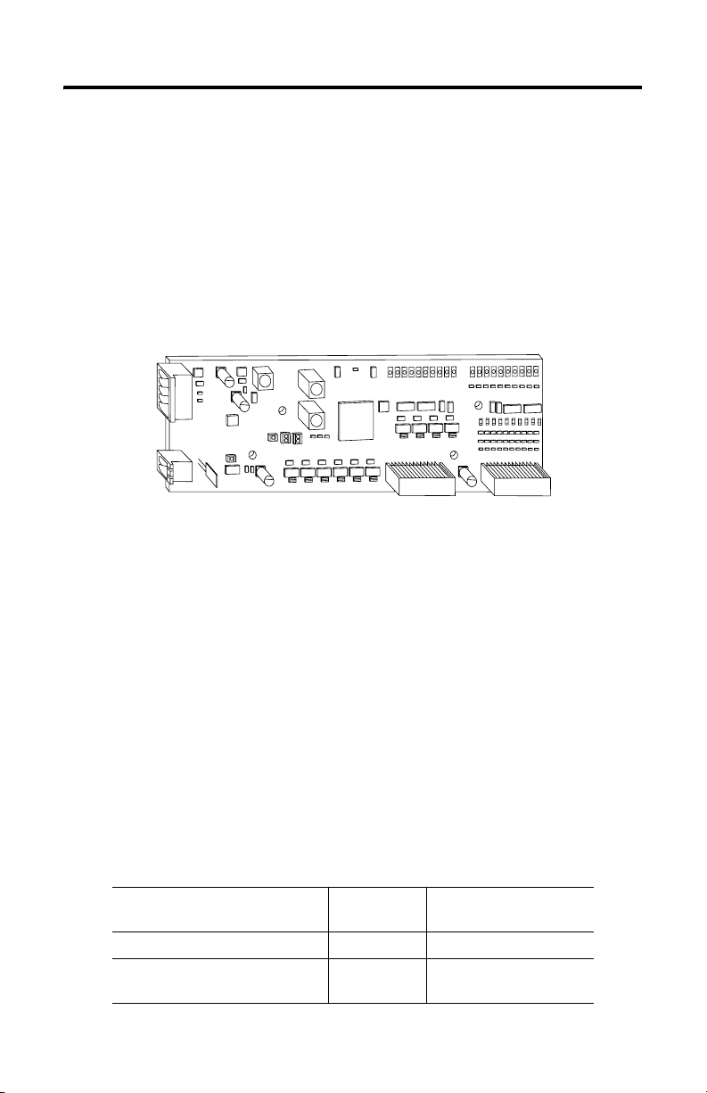
About the Cards
The 1799 Zone Control I/O cards are 20-point I/O cards that communicate via the
DeviceNet network. These cards are intended for material handling and other applications.
The cards also have Zone Interlocking Protocol (ZIP) capability, which lets the cards
communicate directly with each other without hard wiring them together and using a scanner.
These cards have 10 inputs and 10 outputs. Inputs are 24V dc sourcing (PNP) or sinking
(NPN). Outputs are self-protected 24V dc sourcing (1799-ZCIOB and
sinking (1799-ZCIOV and
-D10U10VZC
).
-D10U10BZC
43040
) or
Parts List
Your package contains:
• One 1799 Zone Control card
• DeviceNet connector
• Auxiliary power connector
• Mounting plate and four mounting screws
• These installation instructions
Optional Hardware
All mating connectors and mounting hardware must be ordered separately. The following
table identifies the different connector and hardware options.
Option Catalog
2 DIN rail brackets (4 screws) 1799-BRKD N/A
2, 12-position, gold-plated I/O mating
connectors
Publication 1799-IN007D-EN-P - October 2005
Number
1799-12SPCON Phoenix - FK-MC
Third Party Supplier &
Part Number
0.5/12-ST-2.5AU - 1923432
Page 5
Zone Control I/O Cards 5
Install the Card
To install the card:
• Set the node address
• Mount the card (brackets, mounting plate)
• Connect the card (DeviceNet network, auxiliary power, I/O)
• Communicate with your card
• Configure the parameters
More detailed information about each of these steps is in the following procedures.
Prevent Electrostatic Discharge
ATTENTION
This equipment is sensitive to electrostatic discharge, which can cause
internal damage and affect normal operation. Follow these guidelines
when you handle this equipment:
• Touch a grounded object to discharge potential static.
• Wear an approved grounding wriststrap.
• Do not touch connectors or pins on component boards.
• Do not touch circuit components inside the equipment.
• If available, use a static-safe workstation.
• When not in use, store the equipment in appropriate static-safe
packaging.
Set the Node Address
Valid node addresses are 00 to 63.
Set the node address using the rotary switches or a DeviceNet configuration tool such as
RSNetWorx for DeviceNet software. Setting the switches between 64 and 99 lets the software
have address control.
IMPORTANT
You must use RSNetWorx for DeviceNet software, revision 3.21 or later
with the Zone Control I/O cards.
Publication 1799-IN007D-EN-P - October 2005
Page 6
6 Zone Control I/O Cards
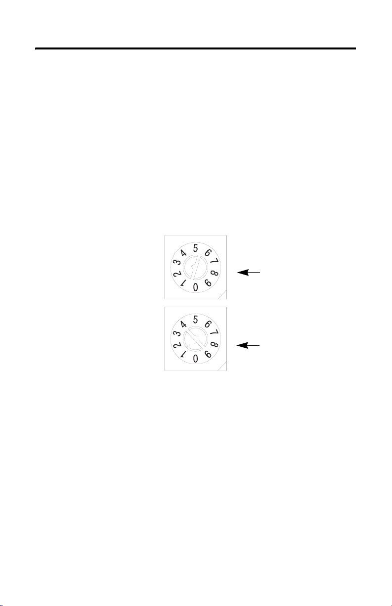
Each card is shipped with the node address set to 63 in the card’s memory. The rotary
switches are set for position 99 at shipment. The switches are located near the center of the
card. The two switches are:
• MSD (most significant digit)
• LSD (least significant digit)
To reset the node address, use a small blade screwdriver to rotate the switches. Line up the
small arrow on the switch with the number setting you wish to use.
The rotary switches are read only when you apply power to the card. Settings between 64 and
99 cause the card to use the last valid node address stored in the card’s memory.
For example, the last setting in memory is 40. If a change is made to 68, and then you apply
power to the card, the address will default to 40.
LSD (S1)
The LSD (S2)
and MSD (S1)
switches are
shown in the
63 position.
MSD (S2)
42496
The card is equipped with AutoBaud detect. AutoBaud lets the card detect the
communication rate on your DeviceNet network and automatically adjusts to that rate.
The card is shipped with AutoBaud enabled.
Publication 1799-IN007D-EN-P - October 2005
Page 7
Zone Control I/O Cards 7
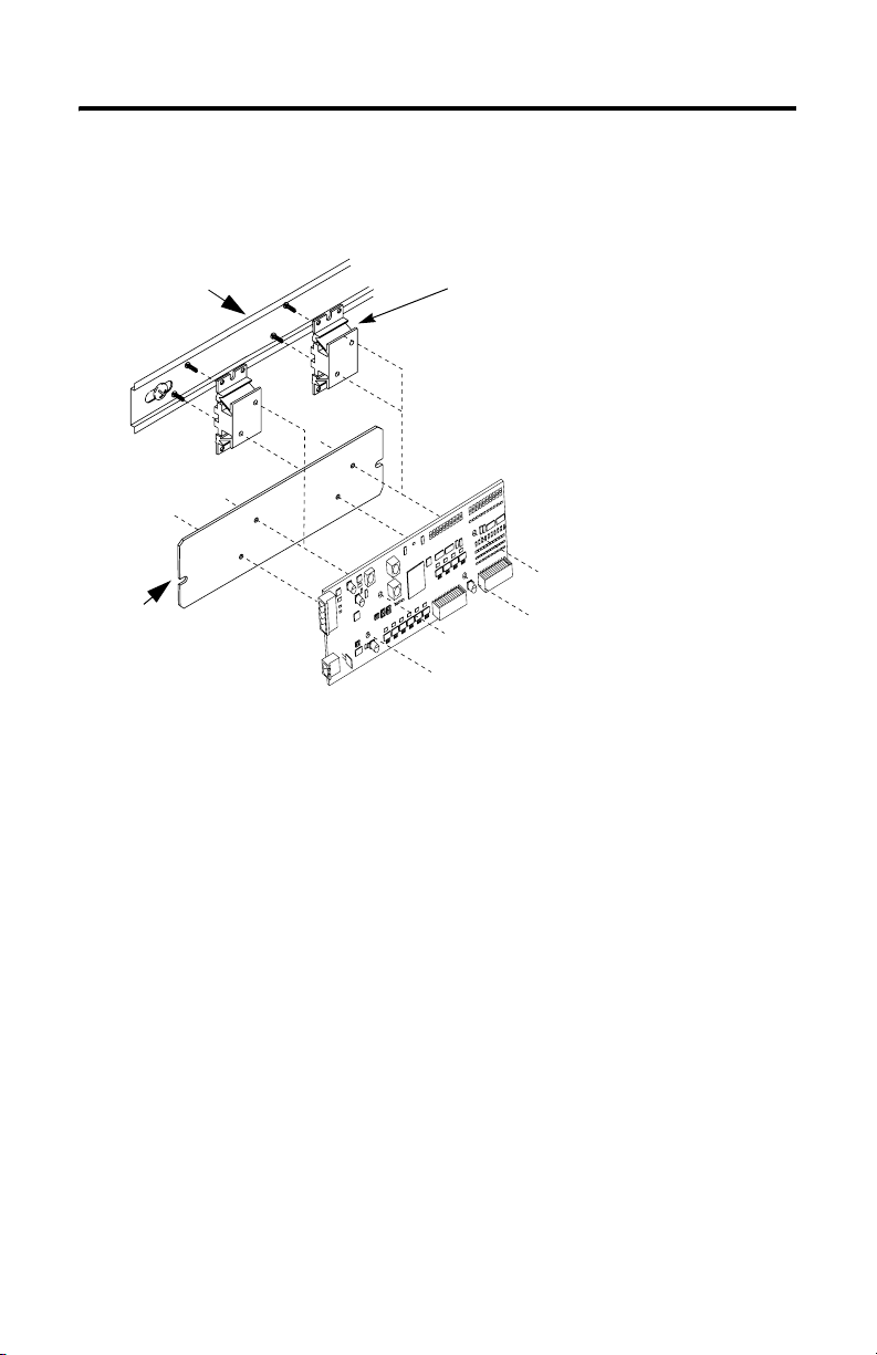
Mount the Card
The Zone Control card comes with a mounting plate. You have the option to order the
DIN-rail brackets (1799-BRKD) for mounting directly on a DIN rail.
DIN Rail
or
Mounting Plate
DIN Rail Bracket
or
43041
You can also mount the card in an enclosure with pre-tapped holes, which accommodate M3
x 0.5 mm screws.
Publication 1799-IN007D-EN-P - October 2005
Page 8
8 Zone Control I/O Cards
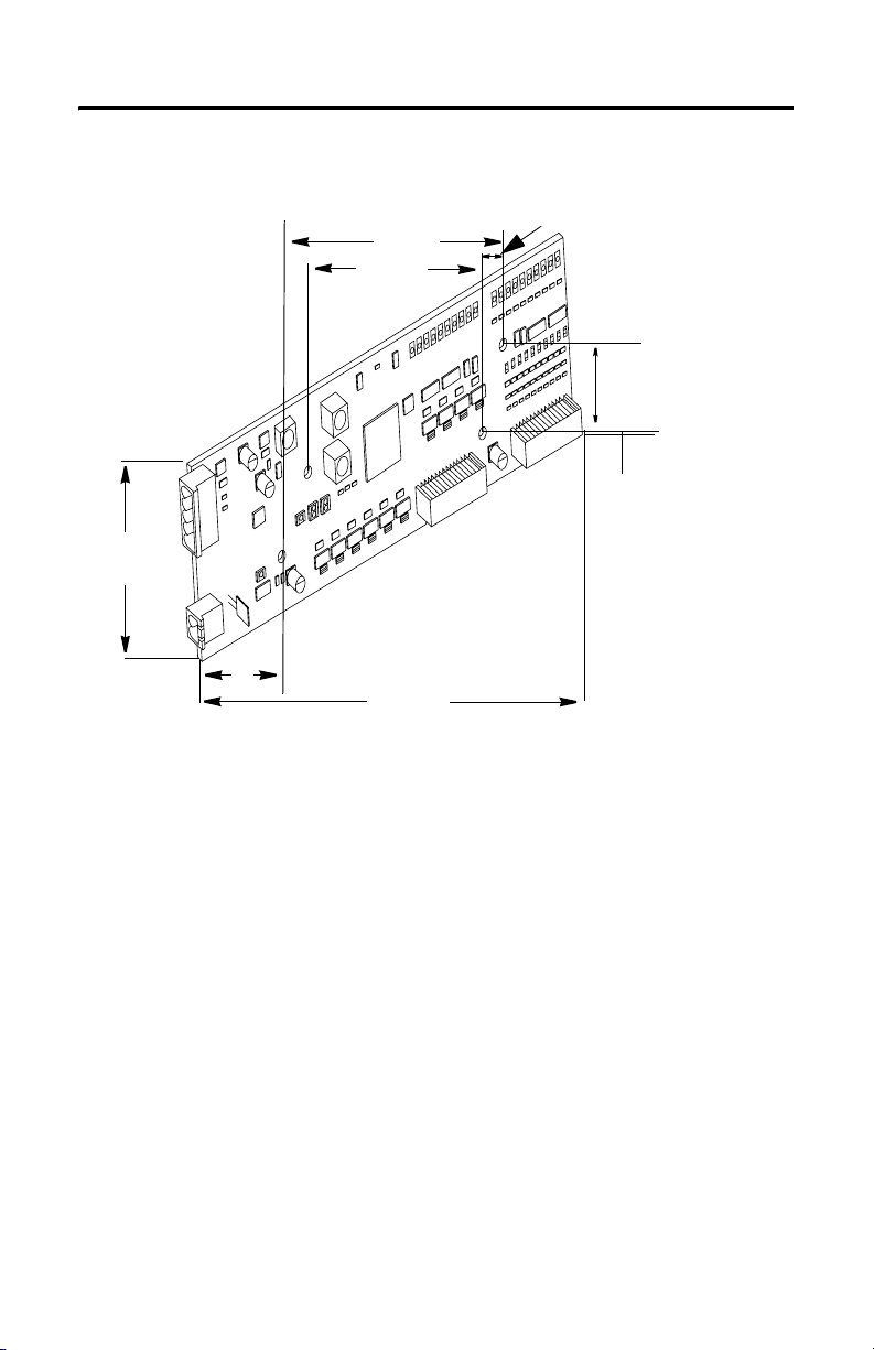
Card Dimensions
50.80 mm
(2.0 in.)
27.30 mm
(1.08 in.)
99.00 mm
(3.90 in.)
76.20 mm
(3.00 in.)
162.56 mm
(6.40 in.)
11.43 mm
(0.45 in.)
19.05 mm
(0.75 in.)
15.88 mm
(0.63 in.)
43042
Publication 1799-IN007D-EN-P - October 2005
Page 9

Zone Control I/O Cards 9
Connect the Card
Use the following pictures and tables to help you connect the DeviceNet connectors, auxiliary
power connectors, and I/O connectors to the card.
Pin 12 (Right)
I/O Connector (P3)
DeviceNet Connector (P2)
Pin 1
(Top)
Auxiliary Power Connector (P1)
Pin 1 (Left)
Pin 2 (Bottom)
Pin 5
(Bottom)
I/O Connector
(P4)
43043
Publication 1799-IN007D-EN-P - October 2005
Page 10

10 Zone Control I/O Cards
The following table identifies the signal for each 1799-D16U16B and 1799-D16U16BL pin
number on the I/O connector.
P1 Auxiliary Power
Connector
Pin Signal Pin Signal Pin Signal
1 24V dc 1 Output 0 1 Input 0
2 24V dc Ret 2 Output 1 2 Input 1
P2 DeviceNet Connector
Pin Insulation Colors 7 Output 5 7 Input 5
1 Black 8 Output 6 8 Input 6
2Blue 924V dc 9In
3 Shield 10 Output 7 10 Input 7
4 White 11 Output 8 11 Input 8
5 Red 12 Output 9 12 Input 9
P3 I/O Connector P4 I/O Connector
3 Output 2 3 Input 2
424V dc Ret 4 In
Common
5 Output 3 5 Input 3
6 Output 4 6 Input 4
Common
Auxiliary Power Specifications
The power source used to supply the auxiliary power to the outputs must be one of the
following:
• a 10 to 30V dc Class 2 power supply, or
• a 10 to 30V dc UL Listed or recognized power supply with isolated outputs limited to
200VA in each ungrounded output line.
This condition requires that the card and power source be mounted in a suitable,
ultimate enclosure with proper spacings maintained.
Publication 1799-IN007D-EN-P - October 2005
Page 11

Zone Control I/O Cards 11
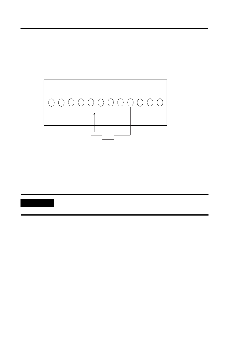
Connect the Field Output Device to the Output Connector (P3)
The 1799-ZCIOB and 1799-D10U10BZC cards have outputs that supply current to your
field output device (sourcing outputs). Use the following wiring diagram to connect the
outputs on this card.
1799-ZCIOB and -D10U10BZC Outputs (Sourcing)
3
0
24V dc
1
2
Return
4
Load
6
24V dc
5
7
9
8
43090
Publication 1799-IN007D-EN-P - October 2005
Page 12
12 Zone Control I/O Cards
The 1799-ZCIOV and 1799-D10U10VZC cards have outputs that receive current from your
field output device (sinking outputs). Use the following wiring diagram to configure the
outputs on this card.
1799-ZCIOV and -D10U10VZC Outputs (Sinking)
c
d
0 2 24V dc
Return
3456
Load
78 91
V
4
2
43091
Connect the Field Input Device to the Input Connector (P4)
The 1799-ZCIOB, 1799-D10U10BZC, 1799-ZCIOV, and 1799-D10U10VZC cards have
universal inputs that provide operation with either sourcing or sinking input devices. The
universal feature lets you configure the inputs as either all sinking or all sourcing. Use the
following wiring diagrams to connect the inputs on the cards.
IMPORTANT
All field input devices in each group of eight must be of the same type,
either sinking or sourcing. The card will not operate if the types are mixed.
Publication 1799-IN007D-EN-P - October 2005
Page 13
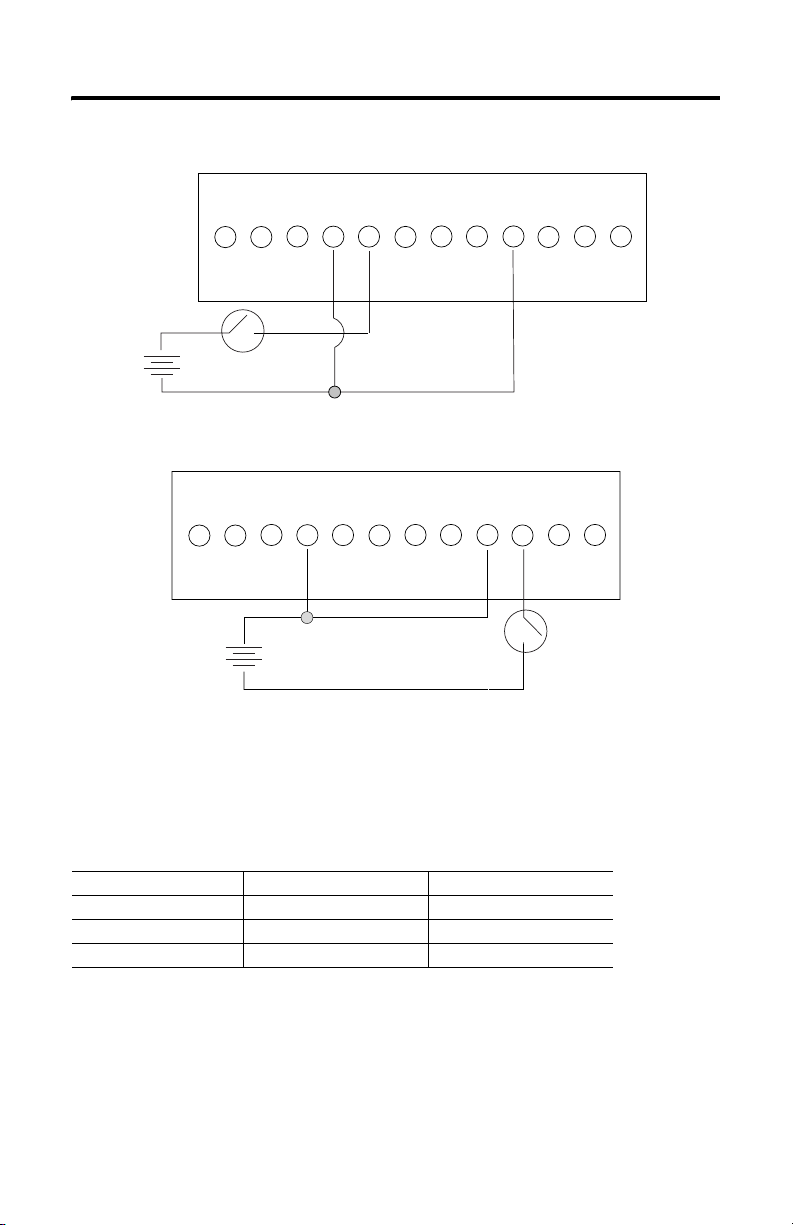
Inputs (Sinking)
Zone Control I/O Cards 13
023456In
+
_
Inputs (Sourcing)
0 2 34 56 7891
Common
+
_
Communicate with the Card
Common
In
In
In
Common
78 91
Common
42493
42494
This card exchanges I/O with the master on the DeviceNet network through a cyclic, polled,
or change-of-state connection.
The card consumes and produces I/O data as follows:
I/O Connection Type Consumes Produces
Cyclic 2 Bytes 7 Bytes
Polled 2 Bytes 7 Bytes
Change-of-state 2 Bytes 7 Bytes
Publication 1799-IN007D-EN-P - October 2005
Page 14

14 Zone Control I/O Cards
Cyclic — the card produces and consumes its I/O cyclically at the rate configured by the
master on the DeviceNet network.
Polled — the master initiates communication by sending its polled I/O message to the card.
The card consumes the message, updates any outputs, and produces a response containing
the input data.
Change-of-state — a production occurs when an input changes. A heartbeat production
occurs if no input condition change occurs within the expected packet rate. This heartbeat
production tells the master that the card is ready to communicate. Consumption occurs when
data changes and the master produces new output data to the card.
Refer to the following table for the word and bit definitions:
Byte Bit 7 Bit 6 Bit 5 Bit 4 Bit 3 Bit 2 Bit 1 Bit 0
Prod 0 Input 7 Input 6 Input 5 Input 4 Input 3 Input 2 Input 1 Input 0
Prod 1 RSVD Logic Ena RSVD Input 9 Input 8
Prod 2 Output 7 Output 6 Output 5 Output 4 Output 3 Output 2 Output 1 Output 0
Prod 3 RSVD Output 9 Output 8
Prod 4 NetOut 7 NetOut 6 NetOut 5 NetOut 4 NetOut 3 NetOut 2 NetOut 1 NetOut 0
Prod 5 CCV 7 CCV 6 CCV 5 CCV 4 CCV 3 CCV 2 CCV 1 CCV 0
Prod 6 CCV 15 CCV 14 CCV 13 CCV 12 CCV 11 CCV 10 CCV 9 CCV 8
Cons 0 Output 7 Output 6 Output 5 Output 4 Output 3 Output 2 Output 1 Output 0
Cons 1 RSVD Output 9 Output 8
RSVD = Reserved, Logic Ena = DeviceLogix enabled, NetOut = Network Output,
CCV = Configuration Consistency Value,
Configure the Parameters
The Zone Control cards have 42 parameters that are configurable through a DeviceNet
configuration tool such as RSNetWorx for DeviceNet software. The DeviceNet
configuration tools require an Electronic Data Sheet (EDS) for the Zone Control cards to
configure the card’s parameters. Find the EDS file can be found at http://www.odva.org.
Publication 1799-IN007D-EN-P - October 2005
Page 15

Zone Control I/O Cards 15
Use the descriptions in the following table to help you configure the non-DeviceLogix
parameters.
Parameter Description
Baud Rate Controls the card’s communication rate.
AutoBaud Enables the card to match the network’s communication rate. When
Input Off-to-On
Filter Time
Input On-to-Off
Filter Time
Output Idle State Controls the state of each output when the DeviceNet master is in an
Output Fault State Controls the state of each output when the card loses communication
Output Idle Value Controls the value that outputs will have when the output idle state is
Output Fault Value Controls the value that outputs will have when the output fault state
enabled, Baud Rate parameter is ignored.
Controls the amount of time the input must be in the on state before
the card reports the input as on.
Controls the amount of time the input must be in the off state before
the card reports the input as off.
idle state.
with the DeviceNet master.
set to use idle value.
is set to use fault value.
These DeviceLogix capable cards have additional parameters that are described in the
DeviceLogix User Manual, publication number ACIG-UM001, and in the Embedded I/O for
DeviceNet Technical Data, publication number 1799-TD001.
Publication 1799-IN007D-EN-P - October 2005
Page 16

16 Zone Control I/O Cards
Troubleshoot the Zone Cards
This card has the following indicators, shown in the picture below:
• Card status indicator
• Network status indicator
• DeviceLogix status
• Auxiliary power indicator
• I/O status indicators
I/0 Status Indicators
Card Status
Auxiliary Power
Indicator
DeviceLogix
Status Indicator
Network Status
Indicator
Indicator
43045
Publication 1799-IN007D-EN-P - October 2005
Page 17

Card Status Indicator (Labeled MOD)
Indication Status
None No power
Green
Blinking
Solid
Red
Blinking
Solid
Needs commissioning
Device operational
Minor fault
Critical fault
Network Status Indicator (Labeled NET)
Indication Status
None Not on-line
Green
Blinking
Solid
Red
Blinking
Solid
On-line/no connections
On-line/connected
Connection timed out
Failed communication: a duplicate
node address exists or card is at
the wrong communication rate
Zone Control I/O Cards 17
DeviceLogix Status Indicator (Labeled DS2)
Indication Status
None Logic disabled
Green
Solid
Blinking
Logic enabled
Local forces applied and local logic enabled
Auxiliary Power Indicator (Labeled AUX PWR)
Indication Status
None No auxiliary power
Green Auxiliary power present
Publication 1799-IN007D-EN-P - October 2005
Page 18

18 Zone Control I/O Cards
I/O Status Indicators (Labeled Inputs and Outputs)
Indication Status
None Input or output point off
Yellow Input or output point on
Technical Support
For additional troubleshooting information on the 1799 Zone Control I/O Cards, access
Rockwell Automation’s technical support services at 440.646.3223 or at http://www.ab.com.
Publication 1799-IN007D-EN-P - October 2005
Page 19

Zone Control I/O Cards 19
Specifications
10 Input/10 Output Card-Cat. Nos. 1799-ZCIOB, -D10U10BZC, -ZCIOV, & -D10U10VZC
Input Specification Max Min
Inputs per Block 10 sinking or sourcing, Type 1 + compatible
Off-state: Voltage
Current
On-state: Voltage
Current
Output Specification Maximum Minimum
Outputs per Block 10 sinking or sourcing, 0.5A, short circuit protected, pilot duty
Output Auxiliary Voltage 30V 10V
On-state Voltage Drop 250 mV -
On-state Current 0.5 A -
Off-state Leakage 20
Card Current
(All Outputs On)
Surge Current - for 10 ms,
Repeatable Every 2 s
(Individual Outputs)
General Specifications
LED Indicators Card Status - red/green, Network Status - red/green, Auxiliary
Dimensions - Millimeters
(Inches)
Operating Temperature IEC 60068-2-1 (Test Ad, Operating Cold),
5V dc
1.5 mA
30V dc
6 mA
µA-
4.0 A -
1.0 A -
Power - green, DeviceLogix Status - green,
Input Point LED - yellow, Output Point LED -yellow
26H x 51W x 163D
(1.0H x 2.0W x 6.4D)
IEC 60068-2-2 (Test Bd, Operating Dry Heat),
IEC 60068-2-14 (Test Nb, Operating Thermal Shock):
o
-10...60
C (14...140 o F)
-
-
10V dc
2 mA
Publication 1799-IN007D-EN-P - October 2005
Page 20

20 Zone Control I/O Cards
10 Input/10 Output Card-Cat. Nos. 1799-ZCIOB, 1799-D10U10BZC, 1799-ZCIOV, &
1799-D10U10VZC
General Specifications (continued)
Storage Temperature IEC 60068-2-1 (Test Ab, Un-packaged Non-operating Cold),
Relative Humidity IEC 60068-2-30 (Test Db, Un-packaged Non-operating Damp
Vibration IEC60068-2-6 (Test Fc, Operating):
Shock IEC60068-2-27 (Test Ea, Unpackaged Shock):
Emissions CISPR 11:
ESD Immunity IEC 61000-4-2:
Radiated RF Immunity IEC 61000-4-3:
EFT/B Immunity IEC 61000-4-4:
Surge Transient Immunity IEC 61000-4-5:
Conducted RF Immunity IEC 61000-4-6:
Enclosure Type Rating None (open-style)
IEC 60068-2-2 (Test Bb, Un-packaged Non-operating Dry Heat),
IEC 60068-2-14 (Test Na, Un-packaged Non-operating Thermal
Shock):
o
-40...85
C (-40...185 o F)
Heat):
5 to 95% non-condensing
5 g @ 10...500 Hz
Operating 30 g
Non-operating 50 g
Group 1, Class A
6 kV indirect contact discharges
10 V/m with 1k Hz sine-wave 80%AM from 30...1000 MHz
10 V/m with 200 Hz 50% Pulse 100%AM at 900 Mhz
±2 kV at 5 kHz on power ports
±4 kV at 2.5 kHz on signal ports
±2 kV at 5 kHz on communications ports
±2 kV line-earth(CM) on power ports
±2 kV line-line(DM) and ±4 kV line-earth(CM) on signal ports
±2 kV line-line(CM) on communications ports
10 Vrms with 1 kHz sine-wave 80%AM from 150 kHz...80 MHz
Publication 1799-IN007D-EN-P - October 2005
Page 21

Zone Control I/O Cards 21
10 Input/10 Output Card-Cat. Nos. 1799-ZCIOB, 1799-D10U10BZC, 1799-ZCIOV, &
1799-D10U10VZC
General Specifications (continued)
DeviceNet Power: Voltage
Current
DeviceNet Power
Circuit Type
Auxiliary Power: Voltage
Current
Auxiliary Supply Power
Rating
Isolation Voltage
(Continuous-voltage
Withstand Rating)
Conductors Wire Size
Wiring Category
(1)
25V dc max
125 mA max
11V dc min
-
Class 2
30V dc max
4.0 A min (all outputs on)
10V dc min
100 mA min
(All Outputs Off)
Isolated outputs limited to 200VA in each ungrounded output
line
Tested to withstand 1000V dc for 60 s
DeviceNet power: 0.25...2.5 mm
stranded copper wire rated at 75
Auxiliary power: 0.80...2.5 mm
stranded copper wire rated at 75
DeviceNet: 0.25...2.5 mm
copper wire rated at 75
(See publication DNET-UM072)
I/O: 0.13...0.5 mm
wire rated at 75
2
(26...20 AWG) solid or stranded copper
o
C or greater.
2
(22...14 AWG) solid or
o
C or greater.
2
(18...14 AWG) solid or
o
C or greater.
2
(22...14 AWG) solid or stranded
o
C or greater.
1 - on signal ports
1 - on power ports
2 - on communications ports
Publication 1799-IN007D-EN-P - October 2005
Page 22

22 Zone Control I/O Cards
10 Input/10 Output Card-Cat. Nos. 1799-ZCIOB, 1799-D10U10BZC, 1799-ZCIOV, &
1799-D10U10VZC
General Specifications (continued)
(2)
Certifications
(When product is marked)
Note: In order to comply with CE Low Voltage Directives (LVD), you must use either a NEC
Class 2, a Safety Extra Low Voltage (SELV) or a Protected Extra Low Voltage (PELV) power
supply to power this adapter. A SELV supply cannot exceed 30V rms, 42.4V peak or 60V dc
under normal conditions and under single fault conditions. A PELV supply has the same
rating and is connected to protected earth.
(1)
Use this Conductor Category information for planning conductor routing. Refer to Publication
1770-4.1, "Industrial Automation Wiring and Grounding Guidelines".
(2)
See the Product Certification link at www.ab.com for Declarations of Conformity, Certificates, and
other certification details.
c-UR-us UL Recognized Component Industrial Control
Equipment, certified for US and Canada
CE European Union 89/336/EEC EMC Directive,
compliant with:
EN 50082-2; Industrial Immunity
EN 61326; Meas./Control/Lab., Industrial
Requirements
EN 61000-6-2; Industrial Immunity
EN 61000-6.4; Industrial Emissions
EN 61131-2; Programmable Controllers (Clause 8,
Zone A & B)
C-Tick Australian Radiocommunications Act, compliant
with: AS/NZS CISPR 11; Industrial Emissions
ODVA ODVA conformance tested to DeviceNet
specifications
RSNetWorx for DeviceNet and DeviceLogix are trademarks of Rockwell Automation, Inc.
Trademarks not belonging to Rockwell Automation are property of their respective companies.
Publication 1799-IN007D-EN-P - October 2005
Page 23

Notes:
Zone Control I/O Cards 23
Publication 1799-IN007D-EN-P - October 2005
Page 24

Rockwell Automation Support
Rockwell Automation provides technical information on the web to assist you in
using its products. At http://support.rockwellautomation.com, you can find
technical manuals, a knowledge base of FAQs, technical and application notes,
sample code and links to software service packs, and a MySupport feature that you
can customize to make the best use of these tools.
For an additional level of technical phone support for installation, configuration and
troubleshooting, we offer TechConnect Support programs. For more information,
contact your local distributor or Rockwell Automation representative, or visit
http://support.rockwellautomation.com.
Installation Assistance
If you experience a problem with a hardware module within the first 24 hours of
installation, please review the information that's contained in this manual. You can
also contact a special Customer Support number for initial help in getting your
module up and running:
United States 1.440.646.3223
Monday – Friday, 8am – 5pm EST
Outside United
States
Please contact your local Rockwell Automation representative for any
technical support issues.
New Product Satisfaction Return
Rockwell tests all of its products to ensure that they are fully operational when
shipped from the manufacturing facility. However, if your product is not
functioning and needs to be returned:
United States Contact your distributor. You must provide a Customer Support case number
Outside United
States
Publication 1799-IN007D-EN-P - October 2005 PN 957955-52
Supersedes Pub lication 1799-IN007C-EN -P - November 2004 Copyright © 20 05 Rockwell Automatio n, Inc. All rights reser ved. Printed in the U.S.A.
(see phone number above to obtain one) to your distributor in order to
complete the return process.
Please contact your local Rockwell Automation representative for return
procedure.
ö
 Loading...