

Page 1
Installation Instructions
WARNING
IMPORTANT
ATTENTION
ATTENTION
ATTENTION
ATTENTION
WARNING
WARNING
AVERTISSEMENT
FLEX I/O DC Power Supply Modules
Cat. No. 1794-PS13 and 1794-PS3
Important User Information
Solid state equipment has operational characteristics differing from those of
electromechanical equipment. Safety Guidelines for the Application, Installation and
Maintenance of Solid State Controls (Publication SGI-1.1 available from your local Rockwell
Automation sales office or online at http://www.ab.com/manuals/gi) describes some
important differences between solid state equipment and hard-wired electromechanical
devices. Because of this difference, and also because of the wide variety of uses for solid
state equipment, all persons responsible for applying this equipment must satisfy themselves
that each intended application of this equipment is acceptable.
In no event will Rockwell Automation, Inc. be responsible or liable for indirect or
consequential damages resulting from the use or application of this equipment.
The examples and diagrams in this manual are included solely for illustrative purposes.
Because of the many variables and requirements associated with any particular installation,
Rockwell Automation, Inc. cannot assume responsibility or liability for actual use based on the
examples and diagrams.
No patent liability is assumed by Rockwell Automation, Inc. with respect to use of
information, circuits, equipment, or software described in this manual.
Reproduction of the contents of this manual, in whole or in part, without written permission of
Rockwell Automation, Inc. is prohibited.
Throughout this manual we use notes to make you aware of safety considerations.
Identifies information about practices or circumstances that can cause
an explosion in a hazardous environment, which may lead to personal
injury or death, property damage, or economic loss.
Identifies information that is critical for successful application and
understanding of the product.
Identifies information about practices or circumstances that can lead to
personal injury or death, property damage, or economic loss. Attentions
help you:
• identify a hazard
• avoid a hazard
• recognize the consequence
Environment and Enclosure
This equipment is intended for use in a Pollution Degree 2 industrial
environment, in overvoltage Category II applications (as defined in
IEC publication 60664-1), at altitudes up to 2000 meters without
derating.
This equipment is considered Group 1, Class A industrial equipment
according to IEC/CISPR Publication 11. Without appropriate
precautions, there may be potential difficulties ensuring
electromagnetic compatibility in other environments due to
conducted as well as radiated disturbance.
This equipment is supplied as "open type" equipment. It must be
mounted within an enclosure that is suitably designed for those
specific environmental conditions that will be present and
appropriately designed to prevent personal injury resulting from
accessibility to live parts. The interior of the enclosure must be
accessible only by the use of a tool. Subsequent sections of this
publication may contain additional information regarding specific
enclosure type ratings that are required to comply with certain
product safety certifications.
See NEMA Standards publication 250 and IEC publication 60529, as
applicable, for explanations of the degrees of protection provided by
different types of enclosure. Also, see the appropriate sections in this
publication, as well as the Allen-Bradley publication 1770-4.1
("Industrial Automation Wiring and Grounding Guidelines"), for
additional installation requirements pertaining to this equipment.
FLEX I/O is grounded through the DIN rail to chassis ground. Use
zinc plated yellow-chromate steel DIN rail to assure proper
grounding. The use of other DIN rail materials (e.g. aluminum,
plastic, etc.) that can corrode, oxidize, or are poor conductors, can
result in improper or intermittent grounding.
Preventing Electrostatic Discharge
This equipment is sensitive to electrostatic discharge, which can
cause internal damage and affect normal operation. Follow these
guidelines when you handle this equipment:
• Touch a grounded object to discharge potential static.
• Wear an approved grounding wriststrap.
• Do not touch connectors or pins on component boards.
• Do not touch circuit components inside the equipment.
• If available, use a static-safe workstation.
If you connect or disconnect wiring while the field-side power is
on, an electrical arc can occur. This could cause an explosion in
hazardous installations. Be sure that power is removed or the area is
nonhazardous before proceeding.
North American Hazardous Location Approval
The following devices are North American Hazardous Location approved:
1794-PS13 and 1794-PS3.
The following information applies when operating this
equipment in hazardou s locations:
Products marked “CL I, DIV 2, GP A, B, C, D” are suitable for
use in Class I Division 2 Groups A, B, C, D, Hazardous
Locations and nonhazardous locations only. Each product is
supplied with markings on the rating nameplate indicating
the hazardous location temperature code. When combining
products within a system, the most adverse temperature
code (lowest “T” number) may be used to help determine the
overall temperature code of the system. Combinations of
equipment in your system are subject to investigation by the
local Authority Having Jurisdiction at the time of installation.
EXPLOSION HAZARD
• Do not disconnect equipment
unless power has been removed or
the area is known to be
nonhazardous.
• Do not disconnect connections to
this equipment unless power has
been removed or the area is known
to be nonhazardous. Secure any
external connections that mate to
this equipment by using screws,
sliding latches, threaded connectors,
or other means provided with this
product.
• Substitution of components may
impair suitability for Class I, Division
2.
• If this product contains batteries,
they must only be changed in an area
known to be nonhazardous.
Informations sur l’utilisation de cet équipement en
environnements dangere ux :
Les produits marqués "CL I, DIV 2, GP A, B, C, D" ne conviennent
qu’à une utilisation en environnements de Classe I Division 2
Groupes A, B, C, D dangereux et non dangereux. Chaque produit
est livré avec des marquages sur sa plaque d’identification qui
indiquent le code de température pour les environnements
dangereux. Lorsque plusieurs produits sont combinés dans un
système, le code de température le plus défavorable (code de
température le plus faible) peut être utilisé pour déterminer le
code de température global du système. Les combinaisons
d’équipements dans le système sont sujettes à inspection par les
autorités locales qualifiées au moment de l’installation.
RISQUE D’EXPLOSION
• Couper le courant ou s’assurer que
l’environnement est classé non
dangereux avant de débrancher
l'équipement.
• Couper le courant ou s'assurer que
l’environnement est classé non
dangereux avant de débrancher les
connecteurs. Fixer tous les
connecteurs externes reliés à cet
équipement à l'aide de vis, loquets
coulissants, connecteurs filetés ou
autres moyens fournis avec ce
produit.
• La substitution de composants peut
rendre cet équipement inadapté à
une utilisation en environnement de
Classe I, Divis ion 2.
• S’assurer que l’environnement est
classé non dangereux avant de
changer les piles.
Publication 1794-IN069D-EN-P - June 2004
Page 2
2 FLEX I/O DC Power Supply Modules
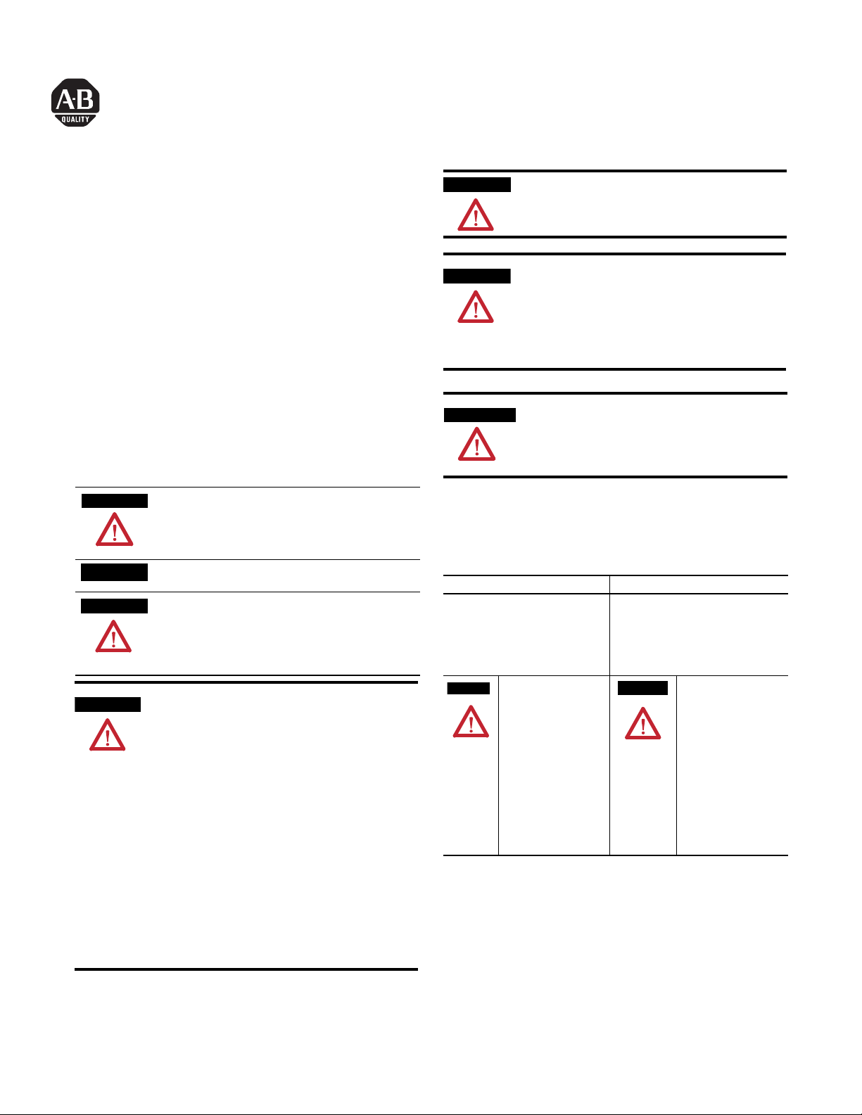
ATTENTION
1
2
3
4
5
6
7
1794-PS13 1794-PS3
B
C
A
C
1794-PS13 shown
IMPORTANT
ATTENTION
ATTENTION
1794-PS3 shown
Power Supply Modules, Cat. No. 1794-PS13 and -PS3
The 1794-PS13 power supply provides sufficient 24V dc power to operate 4
adapter modules. Do not attempt to operate an entire FLEX I/O system with
the 1794-PS13 power supply.
The 1794-PS3 power supply provides sufficient 24V dc power to operate 10
adapter modules. You can use this 1794-PS3 power supply to operate an entire
FLEX I/O system.
Component Identification
1 Power Supply Module
2 Indicator
3 120/230V ac ground
4 120/230V ac common L2/N connections
5 120/230V ac power L1 connections
6 +24V dc connections
7 24V dc common connections
Installing Your Power Supply Module
1. Hook the lip on the rear of the power supply module onto the top of
the DIN rail, and rotate the power supply module onto the rail.
2. Press the power supply module down onto the DIN rail until flush.
Locking tab C will snap into position and lock the power supply
module to the DIN rail.
3. If the power supply module does not lock in place, use a screwdriver
or similar device to move the locking tab down while pressing the
power supply module flush onto the DIN rail, and release the locking
tab to lock the power supply module in place. If necessary, push up on
the locking tab to lock.
Publication 1794-IN069D-EN-P - June 2004
1
2
3
4
5
7
6
During mounting of all devices, be sure that all debris (metal
chips, wire strands, etc.) is kept from falling into the module.
Debris that falls into the module could cause damage on power
up.
4. Connect the power supply wiring as shown under “Wiring” later in
this document.
Note: For panel/Wall mounting, refer to publication 1794-5.13, “Panel
Mounting Kit, Cat. No. 1794-NM1.”
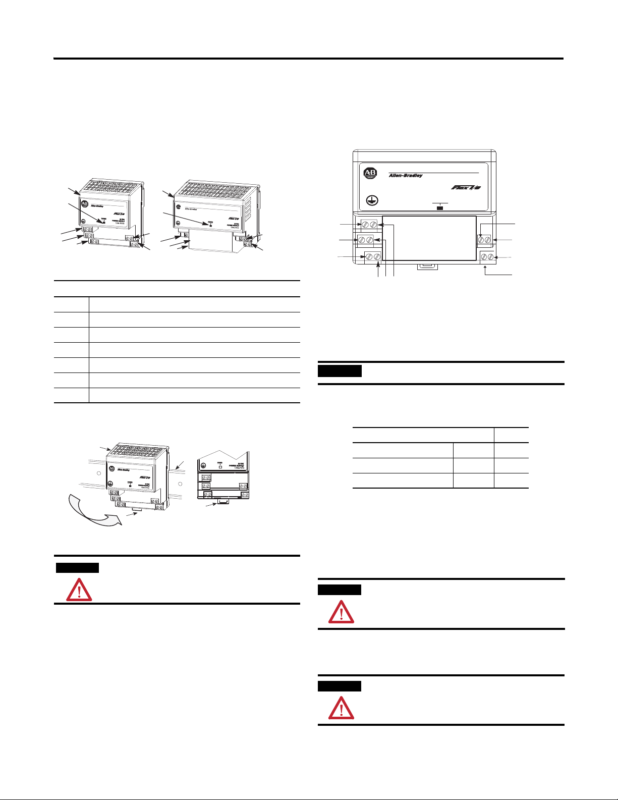
Connecting Wiring
POWER SUPPLY
/ (
1 3
24V DC
1794-PS3
H
I
J
Power
A
B
C
FGED
Terminals A, B and C are 120/230V ac supply terminals. Terminals D, E and F
are available to daisychain this 120/230V ac power to other 1794-PS power
supply modules. If applying 120/230V ac power to the power supply, you can
also power the corresponding 120/230V ac modules in your FLEX I/O
system.
When wiring this power supply, torque terminal screws to 7
pound-inches (0.8Nm).
1. Connect the 120/230V ac power to the left side terminals on the
connectors on the left side of the power supply module as follows:
Connect To
ac ground GND A
120/230V ac common L2/N B
120/230V ac power L1 C
2. Connect terminal G (+24V dc) to the +24V dc terminal on the first
adapter.
3. Connect terminal H (+24V dc common) to the +24V dc common
terminal on the first adapter.
4. Connections I and J are used to pass +24V dc power (G) and -24V
common (H) to the next adapter in the series (if required)
5. Repeat steps 3 and 4 using terminals I and J for the second adapter.
The total length of wire for terminals H, I, J and G must not
exceed 3m (9.8ft). Exceeding the 3m (9.8ft) length can reduce
noise immunity.
6. Connections D, E and F are used to pass 120/230V ac power to
adjacent 1794 power supplies, or to power any corresponding
120/230V ac modules in your FLEX I/O system.
Input and output wiring must be in accordance with Class I,
Division 2 wiring methods and in accordance with the
authority having jurisdiction.
Page 3

3 FLEX I/O DC Power Supply Modules
1794-PS13
1794-PS3
Example of Using a 1794-PS13 Power Supply to
Power 4 Adapter Modules
Power
Adapter
Supply
All dc powered I/O modules
24V dc
Adapter
24V dc from separate source
Indicator Description
ON (green) Output voltage is greater than 20.4V dc, but less than 28V dc
OFF No power applied to power supply
Output voltage exceeded 35V dc, and overvoltage protection
shut the unit down
Output current is above 1.4A (1794-PS13) or above 3.2A
(1794-PS3)
Specifications
24V dc
ac
All ac powered I/O modules
Adapter
24V dc
ac
All ac powered I/O modules
24V dc
Adapter
120V ac
24V dc from separate source
Combination ac and dc powered I/O modules
Diagnostic Indicator
The power supplies have 1 indicator.
Power
Indicator
The power indicator is on (green) when voltage
at the output is between 20.4V dc and 28V dc.
Power
Indicator
The power indicator is on (green) when voltage
at the output is between 20.4V dc and 28V dc.
Specifications - Cat. No. 1794-PS13 and 1794-PS3
1794-PS13 1794-PS3
Nominal Supply Voltage 120V ac, 47-63Hz; 0.6A max.
Voltage Range 85-265V ac
Input Current 0.7 maximum 1.9A maximum
Inrush Current 40A typical, 1 ac cycle @ Vin 265V ac, 55°C
Interruption Output will stay within specification when input drops out for 1/2 cycle @
Output Specifications
Nominal Output +24V dc
Voltage Range 20.4-27.6V dc (includes noise and 5% ac ripple)
Output Current 1.3A maximum 3A maximum (horizontal mount),
Output Power 31.2W 72W
Output Ripple 1200mV peak-to-peak maxim um
Minimum Load 0mA 50mA
Output Surge Sufficient to drive 4 adapters Sufficient to drive 10 adapters
Overvoltage Protection Output internally limited to 35V dc. Cycle power to ree nergize.
Leakage Current 0.5mA rms maximum @ rated input and output
Isolation Voltage Tested at 2500V dc for 1s
Overcurrent Protection 1.4A minimum 3.2A minimum
Thermal Dissipation 23.9 BTU/hr 41.0 BTU/hr
Power Dissipation 7W maximum 12W maximum
Dimensions 3.4H x 2.7W x 2.7D inches
230V ac, 47-63Hz; 0.42A max.
47Hz, 85V ac with maximum load
87H x 69W x 69D mm
120V ac, 47-63Hz; 1.7A max.
230V ac, 47-63Hz; 1.1A max.
2.8A all other mounting (See
derating curve)
3.4H x 3.7W x 2.7D inches
87H x 94W x 69D mm
General Specifications
Environmental Conditions
24V DC
Power
POWER SUPPLY
1794-PS13
COM
24V
24V DC
Power
POWER SUPPLY
1734-PS3
COM
24V
Operating Temperature IEC 60068-2-1 (Test Ad, Operating Cold),
Storage Temperature IEC 60068-2-1 (Test Ab, Un-packaged Non-operating Cold),
Relative Humidity IEC 60068-2-30 (Test Db, Un-packaged Non-operating
Vibration IEC60068-2-6 (Test Fc, Operating):
Shock IEC60068-2-27 (Test Ea, Unpackaged shock)
Emissions CISPR 11:
ESD Immunity IEC 61000-4-2:
Radiated RF Immunity IEC 61000-4-3:
EFT/B Immunity IEC 61000-4- 4:
Surge Transient Immunity IEC 61000-4-5:
Conducted RF Immunity IEC 61000-4-6:
Enclosure Type Rating None (open-style)
IEC 60068-2-2 (Test Bd, Operating Dry Heat),
IEC 60068-2-14 (Test Nb, Operating Thermal Shock):
0 to 55°C (32 to 131°F)
IEC 60068-2-2 (Test Bb, Un-packaged Non-operating Dry Heat),
IEC 60068-2-14 (Test Na, Un-packaged Non-operating Thermal Shock):
–40 to 85°C (–40 to 185°F)
Damp Heat):
5 to 95% non-condensing
5g @ 10-500Hz
Operating 30g
Non-operating 50g
Group 1, Class A (with appropriate en closure)
4kV contact discharges
8kV air discharges
10V/m with 1kHz sine-wave 80%AM from 30 MHz to 1000MHz
±2kV at 5kHz on power ports
±1kV line-line(DM) and ±2kV line-earth(CM) on ac power ports
10Vrms with 1kHz sine-wave 80%AM from 150kHz to 80MHz
Publication 1794-IN069D-EN-P - June 2004
Page 4

Conductors Wire Size
0
0.5
0
2.0
1.0
3.0
10 20 30 40 50 55 60
Max.
Output
Current
(A)
Ambient Temperature
o
C
The area within the curve represents the safe operating range for the module under
various conditions of user supplied 24V dc supply voltages and ambient temperatures.
= Normal mounting safe operating range, (includes ).
= Other mounting positions (including inverted horizontal) safe operating range
2.8
2.5
1.5
Normal Mounting – Horizontal
Other Mounting (including Vertical, and Inverted Horizontal Mounting)
Inches
(Millimeters)
3.4
(87)
3.2
(80)
2.7
(68)
.83 (21)
1794-PS13
3.4H x 2.7W x 2.7D
(87H x 68W x 69D)
1.4
(35)
A
2.3
(59)
A
= Mounting hole dimensions for optional mounting kit
B
B
= DIN rail
2.0
(50)
1.2
(28)
C
C
= Secure DIN rail approximately every 200mm
Power
24V DC
POWER SUPPLY
1794-PS13
24V
COM
Inches
(Millimeters)
3.4
(87)
3.2
(80)
3.7
(94)
1794-PS3
3.4H x 3.7W x 2.7D
(87H x 95W x 69D)
A
B
= DIN rail
2.0
(50)
1.2
(28)
B = Secure DIN rail approximately every 200mm
Power
24V DC
POWER SUPPLY
1794-PS3
24V
COM
A
1794-PS13
1794-PS3
Category
22 to 12 AWG (0.34mm2 - 2.5mm2) stranded copper wire rated at 75°C or
higher
3/64 inch (1.2mm) insulation maximum
1
2
Ter min al S cre w Tor que 7 poun d-inches (0.8Nm)
Certifications (when product is
2
marked)
1 You use this category information for planning conductor routing as described in Allen-Bradley
publication 1770-4.1, Industrial Automation Wiring and Grounding Guidelines.
2 For the latest up-to-date information, see the Product Certification link at www.ab.com for Declarations of
Conformity, Certificates and other certification details. For notification of any additional release notes, refer to
www.ab.com/manuals/
CULUS UL Listed Industrial Control Equipment for Class I, Division
2, Groups A, B, C and D Hazardous locations
CULUS UL Listed Industrial Control Equipment, certified for US
and Canada
CE2 European Union 89/336/EEC EMC Directive,
compliant with:
EN 61000-6-4; Industrial Emissions
EN 50082-2; Industrial Immunity
EN 61326; Meas./Control/Lab., Industria l Requirements
EN 61000-6-2; Industrial Immunity
European Union 73/23/EEC LVD Directive, compliant
with:
EN 61131-2; Programmable Controllers
C-Tick2 - Australian Radiocommunications Act compli ant with:
AS/NZS CISPR 11, Industrial Emissions
Derating Curve for 1794-PS3 (for any mounting other than
horizontal)
Mounting Dimensions
Publication 1794-IN069D-EN-P - June 2004 4 PN 957782-90
Supersedes Publication 1794-IN069C-EN-P - A ugust 2002, and 1794-5.71 - May 2000 Copyright © 2004 Rockwell Automation, Inc. A ll rights reserved. Printed in the U.S.A.
 Loading...