

Page 1

FLEX I/O Isolated Input/Output HART
Analog Modules
Catalog Numbers 1794-IF8IH and1794-OF8IH
User Manual
Page 2
Important User Information
WARNING
IMPORTANT
ATTENTION
SHOCK HAZARD
BURN HAZARD
Solid state equipment has operational characteristics differing from those of electromechanical equipment. Safety Guidelines for the Application,
Installation and Maintenance of Solid State Controls (publication SGI-1.1
http://literature.rockwellautomation.com
) describes some important differences between solid state equipment and hard-wired electromechanical
devices. Because of this difference, and also because of the wide variety of uses for solid state equipment, all persons responsible for applying this
equipment must satisfy themselves that each intended application of this equipment is acceptable.
In no event will Rockwell Automation, Inc. be responsible or liable for indirect or consequential damages resulting from the use or application of this
equipment.
The examples and diagrams in this manual are included solely for illustrative purposes. Because of the many variables and requirements associated
with any particular installation, Rockwell Automation, Inc. cannot assume responsibility or liability for actual use based on the examples and
diagrams.
No patent liability is assumed by Rockwell Automation, Inc. with respect to use of information, circuits, equipment, or software described in this
manual.
Reproduction of the contents of this manual, in whole or in part, without written permission of Rockwell Automation, Inc., is prohibited.
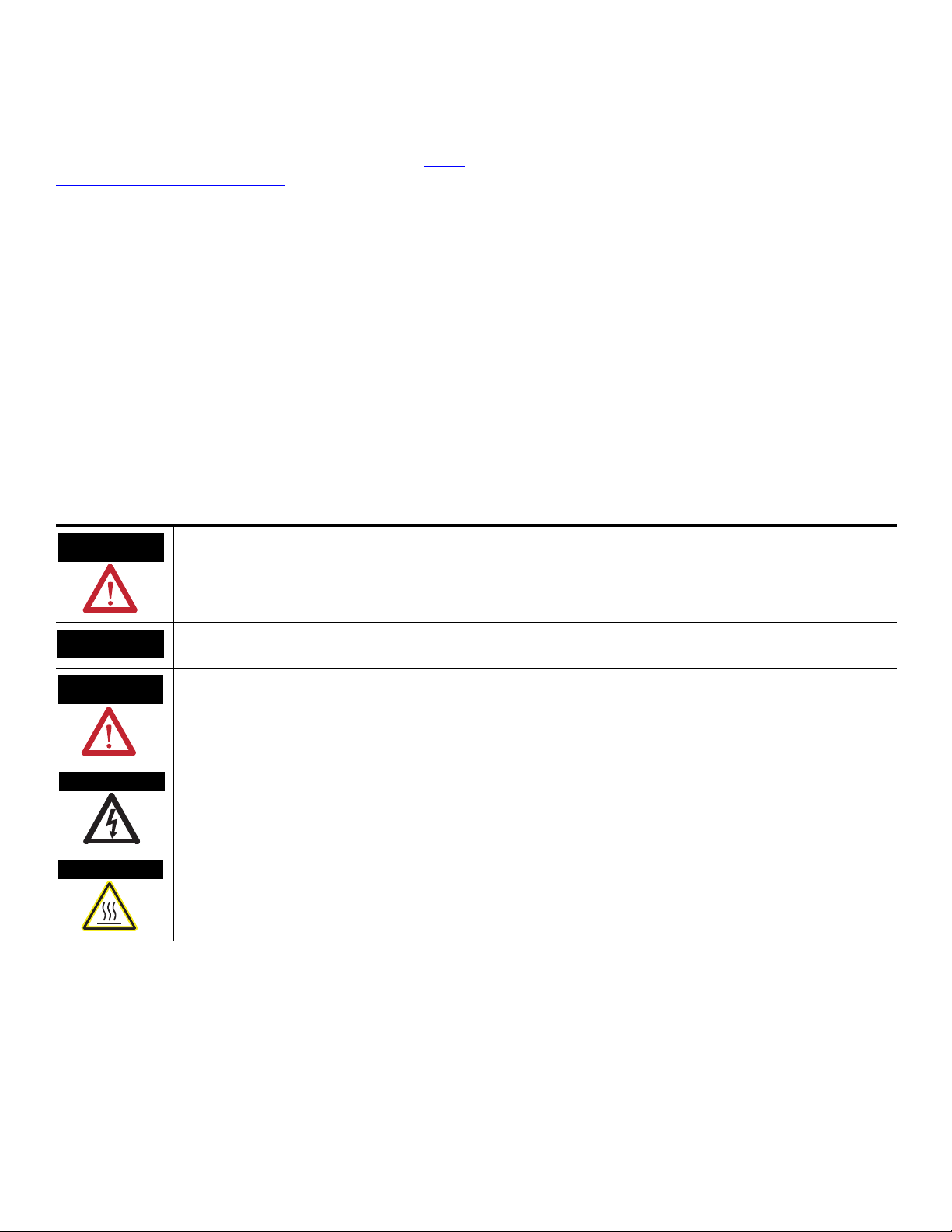
Throughout this manual, when necessary, we use notes to make you aware of safety considerations.
available from your local Rockwell Automation sales office or online at
Identifies information about practices or circumstances that can cause an explosion in a hazardous environment, which may
lead to personal injury or death, property damage, or economic loss.
Identifies information that is critical for successful application and understanding of the product.
Identifies information about practices or circumstances that can lead to: personal injury or death, property damage, or
economic loss. Attentions help you identify a hazard, avoid a hazard, and recognize the consequence.
Labels may be on or inside the equipment, such as a drive or motor, to alert people that dangerous voltage may be present.
Labels may be on or inside the equipment, such as a drive or motor, to alert people that surfaces may reach dangerous
temperatures.
Allen-Bradley, Rockwell Automation, FLEX I/O, RSLogix, RSLinx, RSLogix 5000 and TechConnect are trademarks of Rockwell Automation, Inc.
Trademarks not belonging to Rockwell Automation are property of their respective companies.
Page 3

Summary of Changes
This manual contains new and updated information. Changes throughout this
revision are marked by change bars, as shown to the right of this paragraph.
New and Updated Information
This table contains the changes made to this revision.
Topic Page
Overview 1
Communicate with Programmable Controllers 2
Events Following Power-up 2
Use Alarms on the Input Module 3
Remote Fault Alarm 4
Programming the Remote Fault Alarm 5
Configurable FLEX I/O Analog Module Features 7
Data Format 9
Install the Terminal Base Unit 16
Mount the Analog Modules on the Terminal Base Unit 21
Connections for the 1794-IF8IH HART Analog Input Module
on a 1794-TB3 Terminal Base Unit
Connections for the 1794-OF8IH HART Analog Output Module
on a 1794-TB3 or 1794-TB3S Terminal Base Unit
Ground the Module 24
About the ControlNet and EtherNet Adapters 26
Communication Over the FLEX I/O Backplane 26
I/O Structure 28
23
24
Fault State Data 28
Data Transfer Types 31
Interpret the Status Indicators 57
Use the 1794-IF8IH Module with the Generic Profile 119
Use the 1794-OF8IH Module with the Generic Profile 133
Publication 1794-UM065B-EN-E - September 2010
Page 4

iv Summary of Changes
Notes:
Publication 1794-UM065B-EN-E - September 2010
Page 5

Preface
Why Read This Manual
Who Should Use This Manual
About the Vocabulary
This manual shows you how to use your FLEX I/O analog modules with the
ControlNet products and ControlNet network, and EtherNet products and
EtherNet network. The manual helps you install, program, and troubleshoot
your module. This manual:
You must be able to program and operate a ControlNet product and
ControlNet or Ethernet network to make efficient use of a FLEX I/O
module.
In this manual, we refer to the:
• 1794-IF8IH as the input module
• 1794-OF8IH as the output module
Related Documentation
The following documents contain additional information concerning Rockwell
Automation products. To obtain a copy, contact your local
Rockwell Automation office or distributor.
Resource Description
FLEX I/O 8 Isolated Input HART Analog Module
Installation Instructions, publication 1794-IN115
FLEX I/O 8 Isolated Output Analog Module Installation
Instructions, publication 1794-IN120
FLEX I/O and FLEX XT I/O Selection Guide, publication
1794-SG002
DTM Library FLEX and FLEX EX Release Notes,
publication 1794-RN068
Industrial Automation Wiring and Grounding
Guidelines, publication 1770-4.1
Allen-Bradley Industrial Automation Glossary, AG-7.1
.
.
Common Techniques Used
.
The following conventions are used throughout this manual:
in this Manual
Information on wiring and installing the 1794-IF8IH HART input module.
Information on wiring and installing the 1794-OF8IH HART output module.
A description and overview of the 1794 and 1797 series FLEX I/O modules
compatible control platforms, and overview of how to specify a FLEX I/O system.
Web updates for FLEX I/O and FLEX EX I/O DTM libraries.
More information on proper wiring and grounding techniques.
. A glossary of industrial automation terms and abbreviations.
• Bulleted lists such as this one provide information, not procedural steps.
• Numbered lists provide sequential steps or hierarchical information.
• Italic type is used for emphasis.
v Publication 1794-UM065B-EN-E - September 2010
Page 6

vi Preface
Notes:
Publication 1794-UM065B-EN-E - September 2010
Page 7

Table of Contents
Summary of Changes
About the FLEX I/O HART Analog
Module
Configurable FLEX I/O Analog
Module Features
Install Your FLEX I/O Analog
Modules
New and Updated Information. . . . . . . . . . . . . . . . . . . . . . . . . . . . . . . iii
Why Read This Manual . . . . . . . . . . . . . . . . . . . . . . . . . . . . . . . . . . . . . . v
Who Should Use This Manual. . . . . . . . . . . . . . . . . . . . . . . . . . . . . . . . . v
About the Vocabulary . . . . . . . . . . . . . . . . . . . . . . . . . . . . . . . . . . . . . . . v
Related Documentation. . . . . . . . . . . . . . . . . . . . . . . . . . . . . . . . . . . v
Common Techniques Used in this Manual. . . . . . . . . . . . . . . . . . . . . . . v
Overview. . . . . . . . . . . . . . . . . . . . . . . . . . . . . . . . . . . . . . . . . . . . . . . . . . 1
What FLEX I/O Analog Modules Do . . . . . . . . . . . . . . . . . . . . . . . . . . 1
Communicate with Programmable Controllers . . . . . . . . . . . . . . . . . . . 2
Events Following Power-up . . . . . . . . . . . . . . . . . . . . . . . . . . . . . . . 2
Physical Features of Your Module . . . . . . . . . . . . . . . . . . . . . . . . . . . . . 3
Indicators . . . . . . . . . . . . . . . . . . . . . . . . . . . . . . . . . . . . . . . . . . . . . . 3
Use Alarms on the Input Module . . . . . . . . . . . . . . . . . . . . . . . . . . . . . . 3
Overrange Alarm . . . . . . . . . . . . . . . . . . . . . . . . . . . . . . . . . . . . . . . . 4
Underrange Alarm . . . . . . . . . . . . . . . . . . . . . . . . . . . . . . . . . . . . . . . 4
Remote Fault Alarm . . . . . . . . . . . . . . . . . . . . . . . . . . . . . . . . . . . . . 4
Local Fault Alarm . . . . . . . . . . . . . . . . . . . . . . . . . . . . . . . . . . . . . . . 5
Use the HART Capabilities . . . . . . . . . . . . . . . . . . . . . . . . . . . . . . . . . . . 6
HART Implementation Overview . . . . . . . . . . . . . . . . . . . . . . . . . . . . . 6
Chapter Summary. . . . . . . . . . . . . . . . . . . . . . . . . . . . . . . . . . . . . . . . . . . 6
Overview. . . . . . . . . . . . . . . . . . . . . . . . . . . . . . . . . . . . . . . . . . . . . . . . . . 7
Select Your Analog Input Module Operating Features . . . . . . . . . . . . . 8
Fault Enable . . . . . . . . . . . . . . . . . . . . . . . . . . . . . . . . . . . . . . . . . . . . 8
Input Filter Cutoff . . . . . . . . . . . . . . . . . . . . . . . . . . . . . . . . . . . . . . . 8
Data Format. . . . . . . . . . . . . . . . . . . . . . . . . . . . . . . . . . . . . . . . . . . . 9
Select Your Analog Output Module Operating Features. . . . . . . . . . . 10
Local Fault Mode. . . . . . . . . . . . . . . . . . . . . . . . . . . . . . . . . . . . . . . 10
Latch Mode . . . . . . . . . . . . . . . . . . . . . . . . . . . . . . . . . . . . . . . . . . . 11
Global Reset. . . . . . . . . . . . . . . . . . . . . . . . . . . . . . . . . . . . . . . . . . . 11
Data Format. . . . . . . . . . . . . . . . . . . . . . . . . . . . . . . . . . . . . . . . . . . 11
Fault Alarm . . . . . . . . . . . . . . . . . . . . . . . . . . . . . . . . . . . . . . . . . . . 13
Understand Image Table Mapping and Bit/Word Descriptions . . . . . 13
Chapter Summary. . . . . . . . . . . . . . . . . . . . . . . . . . . . . . . . . . . . . . . . . . 14
Overview. . . . . . . . . . . . . . . . . . . . . . . . . . . . . . . . . . . . . . . . . . . . . . . . . 15
Before You Install Your Analog Module . . . . . . . . . . . . . . . . . . . . . . . 15
Removal and Insertion Under Power . . . . . . . . . . . . . . . . . . . . . . . . . . 15
Install the Module . . . . . . . . . . . . . . . . . . . . . . . . . . . . . . . . . . . . . . . . . 16
Mount on a DIN Rail . . . . . . . . . . . . . . . . . . . . . . . . . . . . . . . . . . . 16
Mount on a Panel or Wall . . . . . . . . . . . . . . . . . . . . . . . . . . . . . . . . 18
Mount the Analog Modules on the Terminal Base Unit . . . . . . . . 21
The HART analog input and output modules mounts
on a 1794-TB3 or 1794-TB3S terminal base unit. . . . . . . . . . . . . . 21
Wire the Terminal Base Units . . . . . . . . . . . . . . . . . . . . . . . . . . . . . . . . 22
Connect Wiring to the FLEX I/O HART Analog Modules . . . . . . . . 22
Connections for the 1794-IF8IH HART Analog Input Module
on a 1794-TB3 Terminal Base Unit . . . . . . . . . . . . . . . . . . . . . . . 23
i Publication 1794-UM065B-EN-E - September 2010
Page 8

ii Table of Contents
Input, Output and Configuration of
the FLEX I/O HART Analog I/O
Modules
1794-IF8IH and 1794-OF8IH
Configuration
Connections for the 1794-OF8IH HART Analog Output Module
on a 1794-TB3 or 1794-TB3S Terminal Base Unit . . . . . . . . . . . . 24
Ground the Module . . . . . . . . . . . . . . . . . . . . . . . . . . . . . . . . . . . . . . . . 24
Chapter Summary. . . . . . . . . . . . . . . . . . . . . . . . . . . . . . . . . . . . . . . . . . 24
Overview. . . . . . . . . . . . . . . . . . . . . . . . . . . . . . . . . . . . . . . . . . . . . . . . . 25
Use Programming Software in Your FLEX I/O Application. . . . . . . 25
About the ControlNet and EtherNet Adapters . . . . . . . . . . . . . . . . . . 26
Communication Over the FLEX I/O Backplane . . . . . . . . . . . . . . . . 26
Scheduled Data Transfer . . . . . . . . . . . . . . . . . . . . . . . . . . . . . . . . . 27
Unscheduled Data Transfer . . . . . . . . . . . . . . . . . . . . . . . . . . . . . . 27
Module I/O Mapping . . . . . . . . . . . . . . . . . . . . . . . . . . . . . . . . . . . 27
I/O Structure . . . . . . . . . . . . . . . . . . . . . . . . . . . . . . . . . . . . . . . . . . . . . 28
Fault State Data . . . . . . . . . . . . . . . . . . . . . . . . . . . . . . . . . . . . . . . . . . . 28
Device Actions . . . . . . . . . . . . . . . . . . . . . . . . . . . . . . . . . . . . . . . . . . . . 28
Communication Fault Behavior . . . . . . . . . . . . . . . . . . . . . . . . . . . 28
Idle State Behavior. . . . . . . . . . . . . . . . . . . . . . . . . . . . . . . . . . . . . . 29
Chapter Summary. . . . . . . . . . . . . . . . . . . . . . . . . . . . . . . . . . . . . . . . . . 29
Overview. . . . . . . . . . . . . . . . . . . . . . . . . . . . . . . . . . . . . . . . . . . . . . . . . 31
Data Transfer Types. . . . . . . . . . . . . . . . . . . . . . . . . . . . . . . . . . . . . . . . 31
Configuration Parameters . . . . . . . . . . . . . . . . . . . . . . . . . . . . . . . . 32
Examples . . . . . . . . . . . . . . . . . . . . . . . . . . . . . . . . . . . . . . . . . . . . . 37
Fault Mode (8 of 1 bit) . . . . . . . . . . . . . . . . . . . . . . . . . . . . . . . . . . 38
Input Filter Cutoff (8 of 3 bits). . . . . . . . . . . . . . . . . . . . . . . . . . . . 39
ADC Conversion Rate, Channel Update Time and Repeatability. 39
Data Format (8 of 4 bits). . . . . . . . . . . . . . . . . . . . . . . . . . . . . . . . . 39
Remote Low Low Alarm Limit (8 of 16 bit) . . . . . . . . . . . . . . . . . 41
Remote High High Alarm Limit (8 of 16 bit). . . . . . . . . . . . . . . . . 42
Low Alarm Limit (8 of 16 bit). . . . . . . . . . . . . . . . . . . . . . . . . . . . . 42
High Alarm Limit (8 of 16 Bit) . . . . . . . . . . . . . . . . . . . . . . . . . . . . 43
HART Disable Channel 0 to 7 (8 of 1 bit). . . . . . . . . . . . . . . . . . . 43
HART Current Fault Limit (8 of 5 bits) . . . . . . . . . . . . . . . . . . . . . 43
Command 3 Disable (8 of 1 bit) . . . . . . . . . . . . . . . . . . . . . . . . . . . 43
Real Time Data (RTD) Profile, Primary Input Parameters . . . . . . . . . 45
Primary Input Data (8 of 16 bits each) . . . . . . . . . . . . . . . . . . . . . . 45
Real Time Data (RTD) Profile, Primary Status Parameters. . . . . . . . . 46
Alarms . . . . . . . . . . . . . . . . . . . . . . . . . . . . . . . . . . . . . . . . . . . . . . . 46
High Alarm (8 of 1 bit each) . . . . . . . . . . . . . . . . . . . . . . . . . . . . . . 48
Low Alarm (8 of 1 bit each) . . . . . . . . . . . . . . . . . . . . . . . . . . . . . . 48
Remote Alarm (8 of 1 bit each). . . . . . . . . . . . . . . . . . . . . . . . . . . . 49
Loop Alarm (8 of 1 bit each). . . . . . . . . . . . . . . . . . . . . . . . . . . . . . 49
Module Diagnostic Status (1 of 8 bits) . . . . . . . . . . . . . . . . . . . . . . 49
HART Status Fields. . . . . . . . . . . . . . . . . . . . . . . . . . . . . . . . . . . . . 51
HART Failure (8 of 1 bit each) . . . . . . . . . . . . . . . . . . . . . . . . . . . . 51
HART Current Fault (8 of 1 bit each) . . . . . . . . . . . . . . . . . . . . . . 52
HART Transmitter List (8 of 1 bit each) . . . . . . . . . . . . . . . . . . . . 52
Secondary Input Data Table, Cyclic EDT Input Data. . . . . . . . . . . . . 52
Publication 1794-UM065B-EN-E - September 2010
Page 9

Table of Contents iii
HART Command 3 Communication Status (8 of 1 bits): . . . . . . . 53
HART Field Device Command and Communication
Status (8 of 8 bits) . . . . . . . . . . . . . . . . . . . . . . . . . . . . . . . . . . . . . . 54
HART Field Device Status (8 of 8 bits) . . . . . . . . . . . . . . . . . . . . . 54
HART Loop Status (8 of 8 bits):. . . . . . . . . . . . . . . . . . . . . . . . . . . 55
HART PV Status (8 of 8 bits): . . . . . . . . . . . . . . . . . . . . . . . . . . . . 55
Primary HART Variable (8 of 32 bits):. . . . . . . . . . . . . . . . . . . . . . 56
Secondary HART Variable (8 of 32 bits):. . . . . . . . . . . . . . . . . . . . 56
Third HART Variable (8 of 32 bits):. . . . . . . . . . . . . . . . . . . . . . . . 56
Fourth HART Variable (8 of 32 bits): . . . . . . . . . . . . . . . . . . . . . . 56
Primary HART Variable Units Code (8 of 8 bits):. . . . . . . . . . . . . 56
Secondary HART Variable Units Code (8 of 8 bits):. . . . . . . . . . . 56
Third HART Variable Units Code (8 of 8 bits):. . . . . . . . . . . . . . . 57
Fourth HART Variable Units Code (8 of 8 bits): . . . . . . . . . . . . . 57
Interpret the Status Indicators. . . . . . . . . . . . . . . . . . . . . . . . . . . . . . . . 57
Module Configuration for the 1794-OF8IH. . . . . . . . . . . . . . . . . . . . . 57
Output Connections . . . . . . . . . . . . . . . . . . . . . . . . . . . . . . . . . . . . 57
Configuration Parameters . . . . . . . . . . . . . . . . . . . . . . . . . . . . . . . . 58
Analog Output Module (1794-OF8IH) . . . . . . . . . . . . . . . . . . . . . 59
Byte Order (2 of 2 bits) . . . . . . . . . . . . . . . . . . . . . . . . . . . . . . . . . . 61
Examples . . . . . . . . . . . . . . . . . . . . . . . . . . . . . . . . . . . . . . . . . . . . . 62
Fault Mode (8 of 1 bit) . . . . . . . . . . . . . . . . . . . . . . . . . . . . . . . . . . 64
Bus Communications and Module Fault Mode (1 of 1 bit). . . . . . 64
HART Disable Channel 0 to 7 (8 of 1 bit). . . . . . . . . . . . . . . . . . . 65
HART Current Fault Limit (8 of 5 bits) . . . . . . . . . . . . . . . . . . . . . 65
Analog Data Format (8 of 4 bits each) . . . . . . . . . . . . . . . . . . . . . . 65
Latch Mode (8 of 1 bit each). . . . . . . . . . . . . . . . . . . . . . . . . . . . . . 67
Analog/Digital Output Mode (8 of 1 bit each) . . . . . . . . . . . . . . . 67
Analog Mode Fault State (8 of 2 bits each) . . . . . . . . . . . . . . . . . . 68
Analog Mode Channel Fault State Value (8 of 16 bits each). . . . . 68
Digital Mode Fault State (8 of 1 bit each). . . . . . . . . . . . . . . . . . . . 69
Command 3 Disable (8 of 1 bit) . . . . . . . . . . . . . . . . . . . . . . . . . . . 69
Real Time Data (RTD) Profile, Status Parameters . . . . . . . . . . . . . . . . 70
Fault Alarm (8 of 1 bit each) . . . . . . . . . . . . . . . . . . . . . . . . . . . . . . 71
Diagnostic Data (1 of 8 bits) . . . . . . . . . . . . . . . . . . . . . . . . . . . . . . 71
HART Status Fields. . . . . . . . . . . . . . . . . . . . . . . . . . . . . . . . . . . . . 72
HART Current Fault (8 of 1 bit each) . . . . . . . . . . . . . . . . . . . . . . 73
HART Transmitter List (8 of 1 bit each) . . . . . . . . . . . . . . . . . . . . 73
Real Time Data (RTD) Profile, Output Parameters. . . . . . . . . . . . . . . 73
Analog Output Data (8 of 16 bits each) . . . . . . . . . . . . . . . . . . . . . 73
Digital Output Data (8 of 1 bit each) . . . . . . . . . . . . . . . . . . . . . . . 73
Global Reset (1 of 1 bit) . . . . . . . . . . . . . . . . . . . . . . . . . . . . . . . . . 74
Fault (1 of 1 bit) and Run/Prog (1 of 1 bit) . . . . . . . . . . . . . . . . . . 74
Secondary Input Data Table, Cyclic EDT Input Data. . . . . . . . . . . . . 75
Secondary Data Table Section Created by the Adapter. . . . . . . . . 75
HART Command 3 Communication Status (8 of 1 bits) . . . . . . . 75
Publication 1794-UM065B-EN-E - September 2010
Page 10

iv Table of Contents
Configure Module Messaging
Troubleshoot Your Module
FLEX I/O HART Module Commands
Additional HART Protocol
Information
FLEX I/O HART Modules Network
Messaging
Use the 1794-IF8IH Module with
the Generic Profile
Status Indicators. . . . . . . . . . . . . . . . . . . . . . . . . . . . . . . . . . . . . . . . . . . 75
Chapter Summary. . . . . . . . . . . . . . . . . . . . . . . . . . . . . . . . . . . . . . . . . . 76
Overview. . . . . . . . . . . . . . . . . . . . . . . . . . . . . . . . . . . . . . . . . . . . . . . . . 77
HART Configuration Quick Start . . . . . . . . . . . . . . . . . . . . . . . . . . . . . 78
Pick HART Input Data Format . . . . . . . . . . . . . . . . . . . . . . . . . . . 78
Enable HART . . . . . . . . . . . . . . . . . . . . . . . . . . . . . . . . . . . . . . . . . 78
Enable Publishing HART Command 3 Variables . . . . . . . . . . . . . 79
Accessing HART Data Using CIP Message Instruction (MSG) . . 79
Fill in The Information Needed for a MSG Instruction . . . . . . . . 79
Select the Attribute Value for the Operation You Want
to Perform . . . . . . . . . . . . . . . . . . . . . . . . . . . . . . . . . . . . . . . . . . . . 80
Retrieve Additional Information About the HART Device . . . . . 81
Get Device Info Block 1 Message . . . . . . . . . . . . . . . . . . . . . . . . . 82
Get Device Info Block 2 Message . . . . . . . . . . . . . . . . . . . . . . . . . 84
Get Device Info Block 3 Message . . . . . . . . . . . . . . . . . . . . . . . . . 85
Reset the Device Info Changed Status Bit Message. . . . . . . . . . . . 87
HART Pass through Message Overview . . . . . . . . . . . . . . . . . . . . 88
Format a HART Pass through Init Request Message . . . . . . . . . . 89
Format a "Get Pass through Message Status" Request . . . . . . . . . 90
HART Failed Reason Code. . . . . . . . . . . . . . . . . . . . . . . . . . . . . . . 92
Format a "Read Pass through Reply" Request . . . . . . . . . . . . . . . . 93
Chapter Summary. . . . . . . . . . . . . . . . . . . . . . . . . . . . . . . . . . . . . . . . . . 94
Overview. . . . . . . . . . . . . . . . . . . . . . . . . . . . . . . . . . . . . . . . . . . . . . . . . 95
Interpret Status Indicators . . . . . . . . . . . . . . . . . . . . . . . . . . . . . . . . . . . 95
Repair . . . . . . . . . . . . . . . . . . . . . . . . . . . . . . . . . . . . . . . . . . . . . . . . . . . 95
Chapter Summary. . . . . . . . . . . . . . . . . . . . . . . . . . . . . . . . . . . . . . . . . . 95
Overview. . . . . . . . . . . . . . . . . . . . . . . . . . . . . . . . . . . . . . . . . . . . . . . . . 97
Protocol Overview . . . . . . . . . . . . . . . . . . . . . . . . . . . . . . . . . . . . . . . . . 97
Universal Commands. . . . . . . . . . . . . . . . . . . . . . . . . . . . . . . . . . . . . . . 98
Common Practice Commands. . . . . . . . . . . . . . . . . . . . . . . . . . . . . . . . 98
Device-specific Commands . . . . . . . . . . . . . . . . . . . . . . . . . . . . . . . . . . 99
Overview. . . . . . . . . . . . . . . . . . . . . . . . . . . . . . . . . . . . . . . . . . . . . . . . 101
Message Structure. . . . . . . . . . . . . . . . . . . . . . . . . . . . . . . . . . . . . . . . . 101
Master-slave Operation . . . . . . . . . . . . . . . . . . . . . . . . . . . . . . . . . 101
Multiple Master Operation . . . . . . . . . . . . . . . . . . . . . . . . . . . . . . 101
Transaction Procedure. . . . . . . . . . . . . . . . . . . . . . . . . . . . . . . . . . 101
Burst Mode (not supported) . . . . . . . . . . . . . . . . . . . . . . . . . . . . . 102
Universal Commands. . . . . . . . . . . . . . . . . . . . . . . . . . . . . . . . . . . . . . 106
Common Practice Commands. . . . . . . . . . . . . . . . . . . . . . . . . . . . . . . 108
Overview. . . . . . . . . . . . . . . . . . . . . . . . . . . . . . . . . . . . . . . . . . . . . . . . 115
Communication . . . . . . . . . . . . . . . . . . . . . . . . . . . . . . . . . . . . . . . . . . 115
HART Frame Enhancements . . . . . . . . . . . . . . . . . . . . . . . . . . . . . . . 118
Overview. . . . . . . . . . . . . . . . . . . . . . . . . . . . . . . . . . . . . . . . . . . . . . . . 119
Background Information . . . . . . . . . . . . . . . . . . . . . . . . . . . . . . . . . . . 119
Configuration . . . . . . . . . . . . . . . . . . . . . . . . . . . . . . . . . . . . . . . . . . . . 120
Byte Order . . . . . . . . . . . . . . . . . . . . . . . . . . . . . . . . . . . . . . . . . . . 120
Publication 1794-UM065B-EN-E - September 2010
Page 11

Use the 1794-OF8IH Module with
the Generic Profile
Index
Table of Contents v
Fault Enable . . . . . . . . . . . . . . . . . . . . . . . . . . . . . . . . . . . . . . . . . . 120
HART Disable . . . . . . . . . . . . . . . . . . . . . . . . . . . . . . . . . . . . . . . . 121
Channel Data Format . . . . . . . . . . . . . . . . . . . . . . . . . . . . . . . . . . 121
Digital Filters . . . . . . . . . . . . . . . . . . . . . . . . . . . . . . . . . . . . . . . . . 123
High Alarm Limit. . . . . . . . . . . . . . . . . . . . . . . . . . . . . . . . . . . . . . 126
Low Alarm Limit . . . . . . . . . . . . . . . . . . . . . . . . . . . . . . . . . . . . . . 126
Remote High High Alarm Limit . . . . . . . . . . . . . . . . . . . . . . . . . . 126
Remote Low Low Alarm Limit. . . . . . . . . . . . . . . . . . . . . . . . . . . 127
HART Command 3 Disable . . . . . . . . . . . . . . . . . . . . . . . . . . . . . 127
Input Map. . . . . . . . . . . . . . . . . . . . . . . . . . . . . . . . . . . . . . . . . . . . . . . 127
Input Data . . . . . . . . . . . . . . . . . . . . . . . . . . . . . . . . . . . . . . . . . . . 127
High Alarm. . . . . . . . . . . . . . . . . . . . . . . . . . . . . . . . . . . . . . . . . . . 128
Low Alarm . . . . . . . . . . . . . . . . . . . . . . . . . . . . . . . . . . . . . . . . . . . 128
Out of Range . . . . . . . . . . . . . . . . . . . . . . . . . . . . . . . . . . . . . . . . . 129
Second Alarm. . . . . . . . . . . . . . . . . . . . . . . . . . . . . . . . . . . . . . . . . 129
Diagnostic Status . . . . . . . . . . . . . . . . . . . . . . . . . . . . . . . . . . . . . . 129
HART Fault . . . . . . . . . . . . . . . . . . . . . . . . . . . . . . . . . . . . . . . . . . 130
HART Current Fault . . . . . . . . . . . . . . . . . . . . . . . . . . . . . . . . . . . 130
HART Transmitter Present. . . . . . . . . . . . . . . . . . . . . . . . . . . . . . 131
Overview. . . . . . . . . . . . . . . . . . . . . . . . . . . . . . . . . . . . . . . . . . . . . . . . 133
Background Information . . . . . . . . . . . . . . . . . . . . . . . . . . . . . . . . . . . 133
Configuration . . . . . . . . . . . . . . . . . . . . . . . . . . . . . . . . . . . . . . . . . . . . 134
Byte Order . . . . . . . . . . . . . . . . . . . . . . . . . . . . . . . . . . . . . . . . . . . 134
Fault Enable . . . . . . . . . . . . . . . . . . . . . . . . . . . . . . . . . . . . . . . . . . 134
Local Fault Mode. . . . . . . . . . . . . . . . . . . . . . . . . . . . . . . . . . . . . . 135
HART Disable . . . . . . . . . . . . . . . . . . . . . . . . . . . . . . . . . . . . . . . . 135
Channel Data Format . . . . . . . . . . . . . . . . . . . . . . . . . . . . . . . . . . 135
Analog Fault Mode . . . . . . . . . . . . . . . . . . . . . . . . . . . . . . . . . . . . 137
Digital Mode . . . . . . . . . . . . . . . . . . . . . . . . . . . . . . . . . . . . . . . . . 140
Digital Fault Mode. . . . . . . . . . . . . . . . . . . . . . . . . . . . . . . . . . . . . 141
Analog Fault Value . . . . . . . . . . . . . . . . . . . . . . . . . . . . . . . . . . . . 141
HART Command 3 Disable . . . . . . . . . . . . . . . . . . . . . . . . . . . . . 141
Output. . . . . . . . . . . . . . . . . . . . . . . . . . . . . . . . . . . . . . . . . . . . . . . . . . 142
Digital Data . . . . . . . . . . . . . . . . . . . . . . . . . . . . . . . . . . . . . . . . . . 142
Fault Reset . . . . . . . . . . . . . . . . . . . . . . . . . . . . . . . . . . . . . . . . . . . 142
Analog Data . . . . . . . . . . . . . . . . . . . . . . . . . . . . . . . . . . . . . . . . . . 142
Input . . . . . . . . . . . . . . . . . . . . . . . . . . . . . . . . . . . . . . . . . . . . . . . . . . . 143
Diagnostic Status . . . . . . . . . . . . . . . . . . . . . . . . . . . . . . . . . . . . . . 143
Module Diagnostic Status (1 of 8 bits) . . . . . . . . . . . . . . . . . . . . . 143
HART Current Fault . . . . . . . . . . . . . . . . . . . . . . . . . . . . . . . . . . . 145
HART Transmitter Present. . . . . . . . . . . . . . . . . . . . . . . . . . . . . . 146
Publication 1794-UM065B-EN-E - September 2010
Page 12

vi Table of Contents
Notes:
Publication 1794-UM065B-EN-E - September 2010
Page 13

Chapter
IMPORTANT
1
About the FLEX I/O HART Analog Module
Overview
This chapter describes the FLEX I/O Highway Addressable Remote
Transducer (HART) analog modules and what you must know and do before
you begin to use them.
Read this chapter to familiarize yourself with the HART analog modules.
Topic Page
What FLEX I/O Analog Modules Do 1
Communicate with Programmable Controllers 2
Use Alarms on the Input Module 3
Use the HART Capabilities 6
HART Implementation Overview 6
Chapter Summary 6
To use all of the features of this module it must be used with the
1794-ACN(R)15 with version 5.1 firmware or later, or the 1794-AENT
with version 4.2 firmware or later.
For more information about using this module with 1794-ACN(R)15
with version 5.1 (or greater) firmware, see 1794-RN071
.
What FLEX I/O Analog Modules Do
1 Publication 1794-UM065B-EN-E - September 2010
The FLEX I/O HART input and output modules must be used in a
ControlNet or EtherNet network.
The 1794-IF8IH module accepts up to 8 analog inputs. The inputs are isolated
and will accept current in either of the following two ranges: 4…20 mA or
0…20 mA. The default input range is 0…20 mA. The inputs have both fixed
hardware filters and selectable firmware digital filters.
Similarly, the 1794-OF8IH module provides as many as 8 analog outputs. The
outputs are isolated and will provide current in either of the following two
ranges: 4…20 mA or 0…20 mA. The default output range is 0…20 mA.
Each module offers:
• local microprocessor intelligence for advanced features.
• full functionality without switches or jumpers.
Page 14

2 About the FLEX I/O HART Analog Module
• multiple data ranges that can be independently programmed for each
channel.
• lead breakage detection.
• overrange/underrange alarms.
• remote transmitter alarm.
Communicate with Programmable Controllers
Data connections are established between the FLEX I/O module and an
Allen-Bradley programmable controller (PLC) to transfer information
between the two at a scheduled rate.
Input module information is then automatically made available in the PLC
data table through the data connection. Reciprocally, output data information
determined by the PLC program is also automatically transferred from the
PLC data table to the output module through the data connection.
In addition, when the data connection is originally established, configuration
information for the module is automatically transferred to it via the network.
Events Following Power-up
You must apply +24V DC power to your FLEX I/O analog I/O modules.
The following sequence of events occurs after power has initially been applied
to your module:
1. The module status indicator will blink red until a connection is
established and a valid configuration is passed to the module.
Publication 1794-UM065B-EN-E - September 2010
2. After the diagnostic check, module configuration information, selected
by the user and downloaded over the network, is applied by the module.
For more information on configuration options, refer to Configurable
FLEX I/O Analog Module Features.
3. Following the module configuration download for the 1794-IF8IH
module, the module begins producing runtime data for the PLC
processor.
Following the module configuration download for the 1794-OF8IH
module, the module applies configuration data to output channels.
4. If any diagnostics or alarms are generated during normal module
operation, the data is returned to the PLC processor.
Page 15
About the FLEX I/O HART Analog Module 3
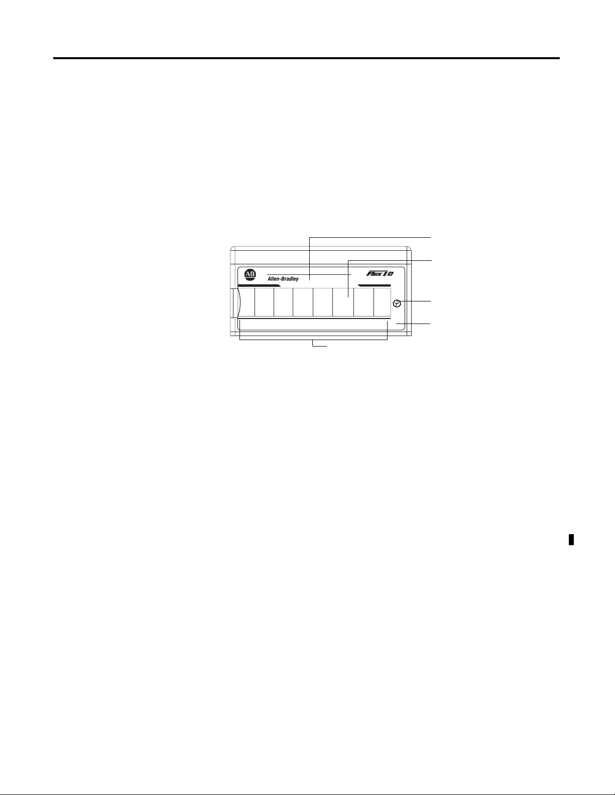
Module type
Removable label
Keyswitch position
indicator (#3)
Power On indicator
Input designators
44811
Physical Features of Your Module
The module label identifies the keyswitch position, wiring and module type.
Use the removable label to note individual designations per your application.
Indicators
Indicators are provided to identify input or output fault conditions, and to
show when power is applied to the module. For example, the 1794-IF8IH
module is shown below.
8 CH HART ISOLATED ANALOG INPUT
IN1IN0 IN2 IN3 IN4
IN5
1794-IF8IH
IN6 IN7
3
PWR
Use Alarms on the Input Module
The 1794-IF8IH FLEX I/O module is capable of generating four alarms:
•Underrange
•Overrange
•Remote Fault
•Local Fault
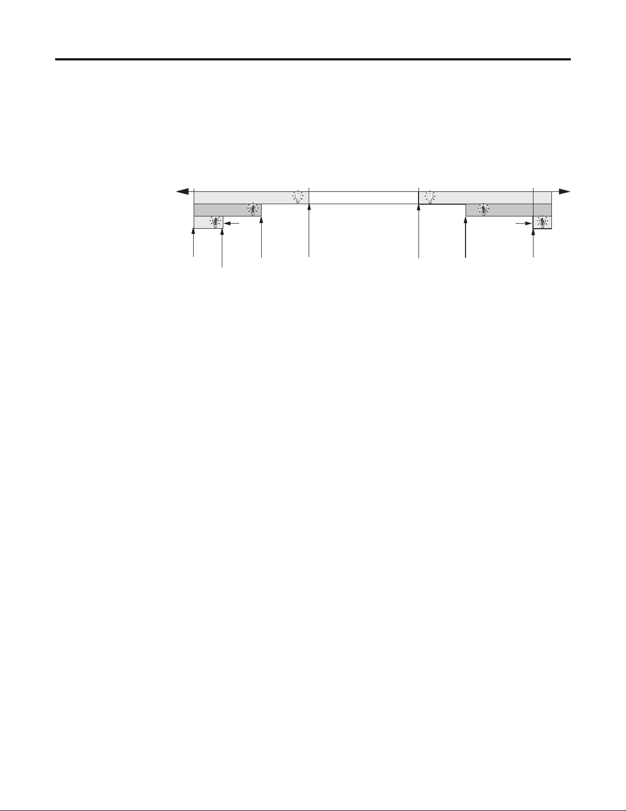
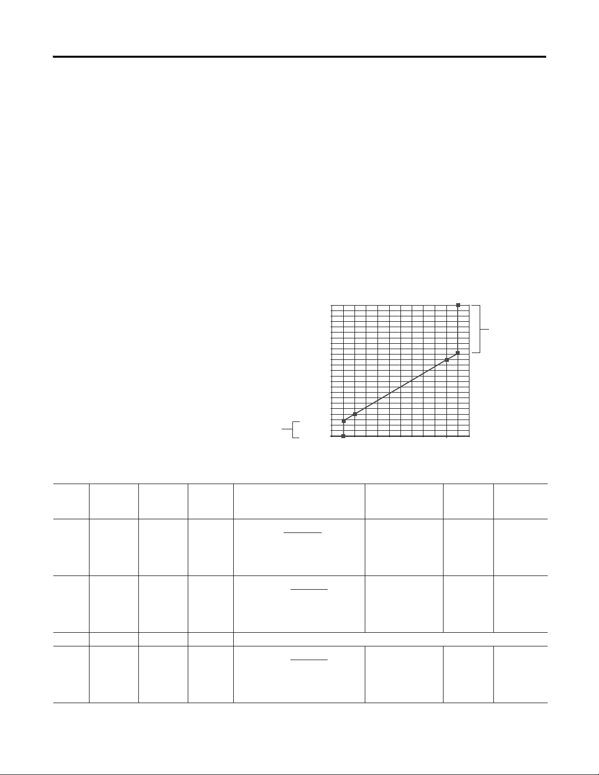
These alarm conditions are described in general terms and as they relate to bits
on the FLEX I/O module on the following pages. The following graphic
shows at what values these alarms are generated for
4…20 mA 1000/mA range.
Publication 1794-UM065B-EN-E - September 2010
Page 16
4 About the FLEX I/O HART Analog Module
0 mA 4 mA 20 mA 22 mA
Remote Fault
Remote Fault
Local
Fault
Local
Fault
Underrange Overrange
Programmable
in 20 0.1 mA
steps by Error
Level 0.1 mA
Steps
parameter
-12.50%
0.00%
-25.00%
Programmable
in 20 0.1 mA
steps by Error
Level 0.1 mA
Steps
parameter
100.00% 112.50%
45149
Data Format Alarm Example
In this example, the normal active data range is 4…20 mA. The alarms are
generated in three overlapping bands.
Physical Input Signal Ranges
Publication 1794-UM065B-EN-E - September 2010
Overrange Alarm
The overrange alarm notifies you when module input is overrange. When the
input signal exceeds 100% (20 mA), an Overrange Alarm is generated.
This alarm stays active at any value above 100% of range and is always enabled
by the module.
Underrange Alarm
The underrange alarm works converse to the overrange. This feature notifies
you when the input signal falls underrange. If the input signal falls below
0% (4 mA), an Underrange Alarm is generated.
This alarm stays active at any value below 0% of range and is always enabled by
the module.
Remote Fault Alarm
The remote fault alarm is intended for use with remote transmitter loops.
For example, the remote transmitter may be measuring temperature and
converting it to a standard mA signal. In such a loop, though, the input module
cannot determine the state of the loop on the far side of the transmitter.
Page 17

About the FLEX I/O HART Analog Module 5
IMPORTANT
IMPORTANT
However, the remote transmitter may be capable of diagnosing a problem in
the remote loop and signal the input module local loop with a preprogrammed
out of range (high or low) value.
The Fault Enable bit allows the 1794-IF8IH module to work with transmitters
like the one just described.
Once the alarm is issued, it remains active as long as the input signal
value remains above the programmed value.
Use Remote Fault Alarm to Determine High-High or Low-Low Alarm Levels
If you do not have a remote transmitter in your loop, this alarm can also be
used to program a high-high or low-low alarm level between the levels which
actuate the overrange or underrange alarms and the high or low local fault
alarms.
Programming the Remote Fault Alarm
For the remote fault alarm, you must program the threshold in 0.1 mA steps at
any level on the high or low end of input signal range. The remote fault alarm
activates if your I/O module receives input signal values of:
• 100.63…111.88% (20.1…21.9 mA) on the high end of input signal
range
or
• -0.63…-11.88% (3.9…2.1 mA) on the low end of input signal range.
Local Fault Alarm
The local fault alarm notifies you when the loop to the transmitter or field
device, if no transmitter is used, is open or shorted.
Once the alarm is issued, it remains active as long as the input signal
value remains in the programmed range.
• 112.50% (22 mA) or higher on the high end of input signal range.
This value indicates a short in the loop.
or
• -12.50% (2 mA) or lower on the low end of input signal range.
Publication 1794-UM065B-EN-E - September 2010
Page 18
6 About the FLEX I/O HART Analog Module
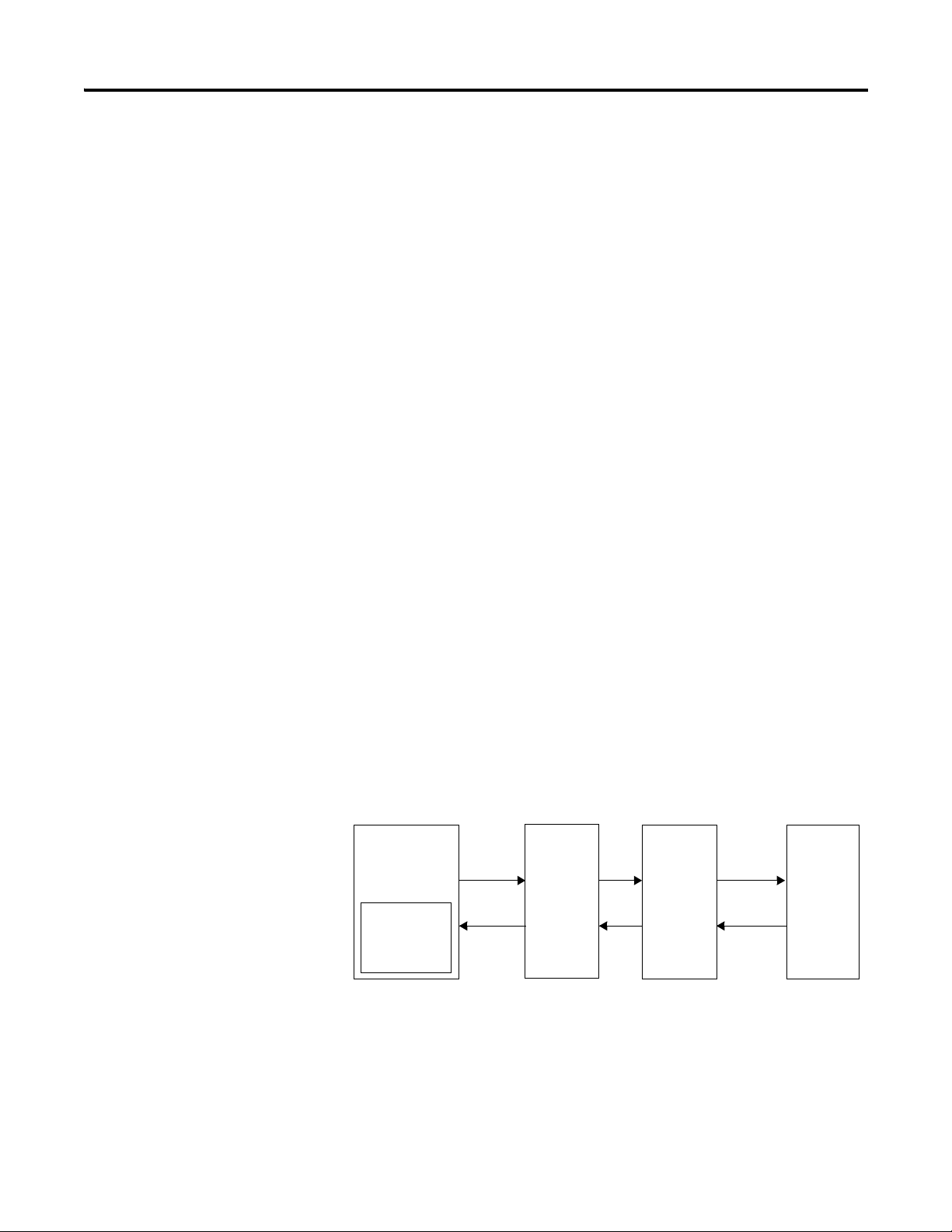
Processor
User program
Adapter FLEX I/O
HART
module
HART
Field Device
Command
Response
for example, HART
Command 3)
Flexbus
4…20 mA with
HART signal
This value indicates an open wire condition in the loop.
The remote fault and local fault alarms are issued with the same bit whether
the cause is an under or overrange. Monitor the overrange and underrange bits
in your programming software to determine if the problem is a high current or
low current.
Use the HART Capabilities
HART Implementation Overview
Before using the HART capabilities, be sure that:
• the I/O module and the associated field device are working properly in
the analog 4 to 20 mA mode.
• the I/O module is configured for 4 to 20 mA range.
• the field device is HART capable.
• no more than one HART field device is connected to each channel.
• input filtering is set to a valid (defined) value.
The FLEX I/O HART modules act as intelligent HART multiplexers.
Basically, the module learns which HART devices are attached to its channels
and then routes HART messages, as appropriate, between the HART field
devices and the flexbus. Since the HART modules act as intelligent HART
multiplexers, HART commands can be issued to the HART modules
themselves.
Communication on the flexbus occurs between the adapter and the HART
module. The adapter converts these messages to the appropriate network
format for communication with the controlling processor. The controlling
processor gets its command from the user program, storing the responses in
its memory.
Chapter Summary
Publication 1794-UM065B-EN-E - September 2010
In this chapter, you learned about FLEX I/O analog I/O modules and HART
module capabilities. Read the next chapter to learn about configurable features
on your module.
Page 19

Chapter
IMPORTANT
Configurable FLEX I/O Analog Module
Features
2
Overview
Read this chapter to familiarize yourself with configurable features on the
input and output analog modules
Topic Page
Select Your Analog Input Module Operating
Features
Select Your Analog Output Module Operating
Features
Understand Image Table Mapping and Bit/Word
Descriptions
Chapter Summary 14
HART configurable features described in this chapter include the following
Analog/Digital Configurable Features on FLEX I/O Analog I/O Modules
1794-IF8IH Input Module 1794-OF8IH Output Module
Fault Mode Output Enable
High Low Error Level Module Fault State Mode
Input Filter Cutoff Local Fault Mode
Data Format Data Format
8
10
13
Global Reset
7 Publication 1794-UM065B-EN-E - September 2010
Analog Fault State
Latch Retry Mode
Fault Alarm
You must use the I/O configuration portion of your PLC programming
software to select and configure these features. This manual assumes
familiarity with the programming software. A brief description of
each module feature is provided here. For more information on your
programming software, refer to the software user manual.
Page 20

8 Configurable FLEX I/O Analog Module Features
IMPORTANT
IMPORTANT
Select Your Analog Input Module Operating Features
All features of the 1794-IF8IH analog input module are independently
configurable.
The default selection value for all parameters is 0.
Fault Enable
Your input modules are capable of indicating various fault conditions,
depending on the input signal value. Use the Fault Enable feature to enable or
disable two alarms:
•Remote Fault Alarm
•Local Fault Mode
Use your programming software to set the Fault Enable bit to 0 to disable
these alarms. Set the bit to 1 to enable them.
Fault Enable will only enable or disable the Remote and Local Fault
alarms. It does not affect the Underrange and Overrange alarms. They
are always active.
For more information refer to Remote Fault Alarm and Local Fault Alarm.
Input Filter Cutoff
Six available input filter settings allow you to choose the best rolloff frequency
for input channels on your I/O module. When choosing a filter, remember
that time filter selection affects your input signal’s accuracy.
For example, if you choose the highest frequency of 470 Hz (filter 0), signal
noise is more likely to affect the reading, but the slowest frequency of 4.17 Hz
(filter 5) provides the most accurate signal due to incoming noise filtering.
Refer to the Input Filter Frequency table to decide which input filter to use in
your FLEX I/O analog I/O application:
Input Filter Frequency
01234567
470 Hz 62 Hz 19.6 Hz 16.7 Hz 10 Hz 4.17 Hz n/a n/a
Choose the best input filter cutoff in your programming software.
Publication 1794-UM065B-EN-E - September 2010
Page 21

Configurable FLEX I/O Analog Module Features 9
input
(
20
)
Datatable = 10000
Datatable = 10000
√
input
20
IF...Square_Root_Threshold
< 10000
√
input
20
Else...datatable = 0
input
(
20
)
Datatable = 65535
input-4
(
16
)
Datatable = 10000
Datatable = 10000
√
IF...Square_Root_Threshold
< 10000
√
Else...datatable = 0
input-4
16
input-4
16
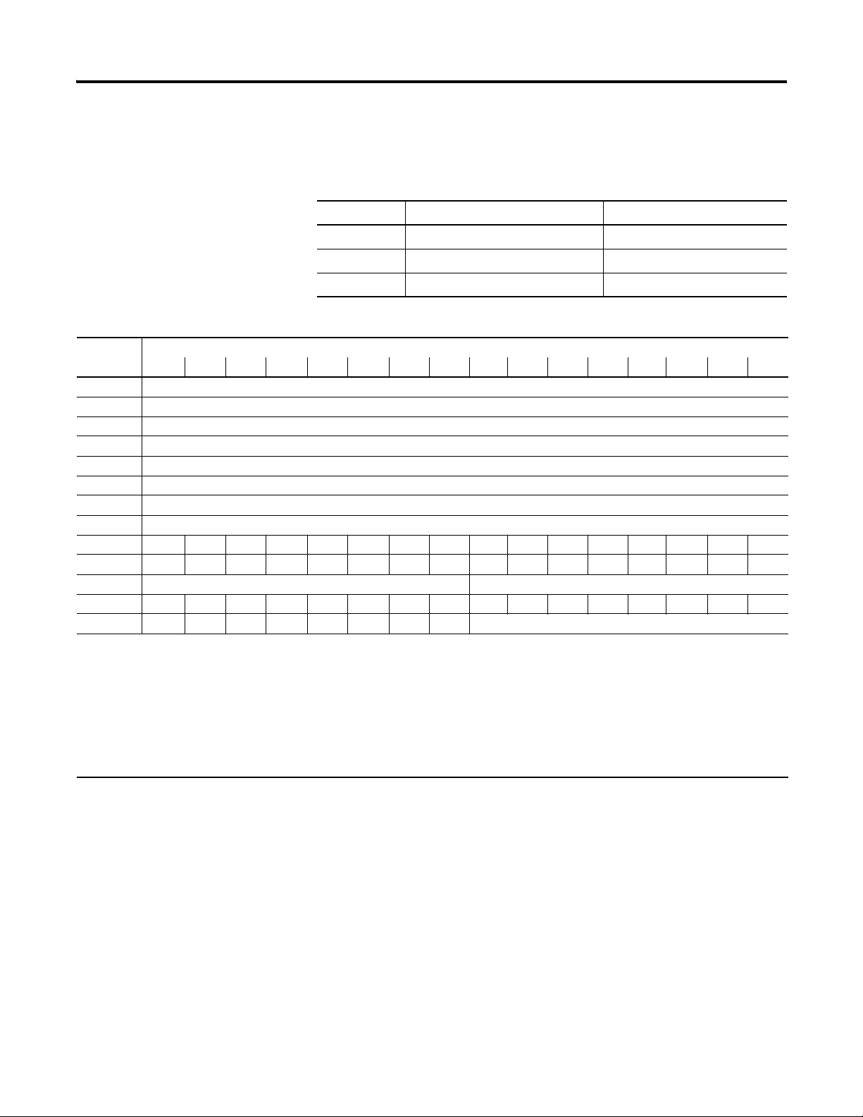
Data Format
You must choose a module data format in your user program. Formats 8, 9, 10
and 15 are not used. If they are selected for a channel quad, a configuration
fault will occur and will be reported as Diagnostic Data 2. All data for that
channel quad will be set to zero (0).
Formats 5, 12, 13 and 14 are 2’s complement data formats, and will return data
in that form.
12 Formats are available
1794-IF8IH Data Formats
Data
Format
0 0…20 mA
1 0…20 mA
2 0…20 mA
3 0…20 mA
4 4…20 mA
5 4…20 mA
Format Resolution Input
as mA
as %
as √%
as unsigned
integer
as mA
as %
0.1 % of
0…20 mA
0.2 % of
0…20 mA
0.19 % of
0…20 mA
0.03 % of
0…20 mA
0.1 % of
4…20 mA
0.16 % of
4…20 mA
Default format is 0
The data format selected interprets input readings and returns them to the
PLC.
Module Data Processing Data Table Value
Range
0…22 mA Datatable = 1000 (input) 0…22000
0…22 mA 0…11000
0…22 mA 0…10488
0…20 mA 0…65535
2…22 mA Datatable = 1000 (input) 2000…22000
2…22 mA -1250…+11250
…20 mA
(Interpretation)
(0…22.000 mA)
(0…110.00%)
(0…104.88%)
(0…22 mA)
(2.000…22.000
mA)
(2’s complement)
(-12.50%…+112.5
0%)
Count
per mA
1000 With
500
524
3276
1000
625 With
Error
Steps
error
steps
error
steps
6 4…20 mA
as √%
0.17 % of
4…20 mA
4…22 mA 0…10607
(0…106.07%)
Publication 1794-UM065B-EN-E - September 2010
With
error
steps,
under-r
ange
not
allowed
Page 22

10 Configurable FLEX I/O Analog Module Features
input-4
(
16
)
Datatable = 65535
input
(
22
)
Datatable = 55000
input-4
(
16
)
Datatable = 10000
input-4
(
16
)
Datatable = 10000
input-4
(
16
)
Datatable = 10000
IMPORTANT
1794-IF8IH Data Formats
Data
Format
7 4…20 mA
8 Not assigned
9
10
11 0…20 mA
12 4…20 mA
13 4…20mA
14 4…20 mA
15 Not assigned
Format Resolution Input
as unsigned
integer
as A/D
count
as %
as %
as %
0.03% of
4…20 mA
0.04% of
0…20 mA
0.16% of
4…20 mA
0.16% of
4…20 mA
0.16% of
4…20 mA
Module Data Processing Data Table Value
Range
0…22 mA 0…55000
3.6…21 mA -250 … +10625
3…21 mA -625 … +10625
2…22 mA -1250 … +11250
(Interpretation)
0…65535
(4…20 mA)
(0…22 mA)
(2’s complement)
(-2.50…+106.25%)
(2’s complement)
(-6.25…+106.25%)
(2’s complement)
(-12.50…+112.50
%)
Count
per mA
4095 With
2500 All
625 NAMU
Error
Steps
error
steps
fixed
R NE 4
all fixed
All
fixed
Select Your Analog Output Module Operating Features
All features of the 1794-OF8IH analog output module are independently
configurable.
The default selection value for all parameters is 0.
Local Fault Mode
The Local Fault Mode can be programmed to determine how the module
responds to communications faults and internal module faults.
When setting the Local Fault Mode feature in your programming software, set
this feature’s bit to 0 to use the analog fault state or digital fault state only if a
communications fault occurs. Set the bit to 1 to use the Analog Fault state or
Digital Fault state if any fault occurs.
Publication 1794-UM065B-EN-E - September 2010
Page 23

Configurable FLEX I/O Analog Module Features 11
Latch Mode
Latch Mode determines channel operation under wire-off or lead-break fault
conditions. This feature is available for each channel. Channel detection occurs
on a continuous basis. If a fault is detected, the channel fault alarm is set.
If Latch mode is enabled when a fault occurs, the fault will remain latched in
its fault state until a Global Reset (see below) is issued. If Latch mode is
disabled when a fault occurs, the channel reports a fault until the fault is
corrected. Global Reset is not necessary if Latch mode is disabled.
When using your programming software, set the Latch mode bit to 0 to disable
the feature. Set the bit to 1 to enable it.
Global Reset
Global Reset works in conjunction with Latch mode during fault conditions. If
Latch mode is enabled and a fault condition occurs, the channel operating with
a fault remains in this condition (with analog or digital fault state implied) until
a Global Reset is issued. The Global Reset feature resets all outputs of a
particular channel group to accept normal system output data.
The Global Reset feature is an edge triggered signal. Use your programming
software to set the Global Reset bit to 1 for normal operation. Resetting of
outputs occurs during the 1 to 0 transition.
Data Format
You must choose a module data format in your user program. Refer to
1794-OF8IH Data Formats for an explanation of each bit. Data Formats 2, 5,
6, 8, 9, 10, 11, 12, 13 and 15 are not assigned.
When choosing a data format, remember the following:
• If an unassigned Analog Data Format is selected, the module sets
Diagnostic Data to 2 for configuration failure and puts affected
channels in the corresponding fault state.
• An unconfigured module channel can be assumed to have the default
configuration Analog Data Format 0, 0 to 20 mA and Analog Mode
Fault State minimum range. If a non-assigned format is selected, then
the diagnostic 2 for configuration failure is set and the module channel
goes to the default fault state minimum range.
Publication 1794-UM065B-EN-E - September 2010
Page 24
12 Configurable FLEX I/O Analog Module Features
Diagnostic Data error 11
= data out of range
Diagnostic Data error 11
= data out of range
04812162024
Output mA
datatable
20.000
16.000
12.000
8.000
4.000
0.000
-4.000
Output =
datatable
(
1000
)
Output = 20
datatable
(
10000
)
Output = 20
datatable
(
65535
)
• If on the other hand, the configuration had been changed, from the
default, and then it was changed again to a non-assigned format, then
the diagnostic bit 2 for configuration failure is set and the module goes
to the fault state for the last valid configuration.
• Formats 13 and 14 are 2’s complement data formats, and require data to
the module in that form.
• Range: 0…15
•Default: 0
• Data Table Reference: data format, word 12 and 13, bits 0…3, bits 4…7
If data is sent to the module which is out of range, the value will be clipped
and Diagnostic Data will be set to 11 data out of range.
Example of Analog Format 14 and Data Clipping Performance.
1794-OF8IH Data Formats
Data
Format
0mA as
1 % as
2 0…20 mA — 0…22 mA Not Assigned
3 Unsigned
Publication 1794-UM065B-EN-E - September 2010
Format Resolution Full
Output
Range
0…20 mA
0…20 mA
integer as
0…20 mA
0.1% of
0…20 mA
0.2% of
0…20 mA
0.03% of
0…20 mA
0…22 mA 0…22000
0…22 mA 0…11000
0…20 mA 0…65535
Module Data Processing Data Table Value
(Interpretation)
(0…22.000 mA)
(0…110.00%)
(0…20 mA)
Count per
mA/
Resolution
1000/
1.0 µA
500/
2.0 µA
3276/
0.305 µA
Analog Fault
State
Min=0 mA
Max=22 mA
hold
Last=hold
FS value
Min=0 mA
Max=22 mA
hold
Last=hold
FS value
Min=0 mA
Max=20 mA
hold
Last=hold
FS value
Page 25

1794-OF8IH Data Formats
Output =
datatable
(
1000
)
Output = 16
datatable
(
65535
)
+ 4
Output = 16
datatable
(
10000
)
+ 4
Configurable FLEX I/O Analog Module Features 13
Data
Format
4mA as
5 4…20 mA — 4…20 mA Not assigned
6 4…20 mA 4…20 mA Not assigned
7 Unsigned
8 0…20 mA 0…20 mA Not assigned
9 0…20 mA 0…20 mA Not assigned
10 0…20 mA 0…20 mA Not assigned
11 0…20 mA 0…20 mA Not assigned
12 4…20 mA Not assigned
13 4…20 mA Not assigned
14 % as
15 4…20 mA 4…20 mA Not assigned
Format Resolution Full
Output
Range
4…20 mA
integer as
4…20 mA
4…20 mA
0.1% of
4…20 mA
0.03% of
4…20 mA
0.16% of
4…20 mA
2…22 mA 2000…22000
4…20 mA 0…65535
2…22 mA -1250 … +11250
Module Data Processing Data Table Value
(Interpretation)
(2.000…22.000 mA)
(4…20 mA)
(2’s complement)
(-12.50% …
+112.50%)
Count per
mA/
Resolution
1000/
1.0 µA
4095/
0.244 µA
625/
1.6 µA
Analog Fault
State
Min=2 mA
Max=22 mA
hold
Last=hold
FS value
Min=4 mA
Max=20 mA
hold
Last=hold
FS value
Min=2 mA
Max=22 mA
hold
Last=hold
FS value
Understand Image Table Mapping and Bit/Word Descriptions
Fault Alarm
Fault Alarm selects whether the channel fault detection is enabled or disabled.
There is a 100 Hz (10 ms) filter for wire off or lead break detection.
Use your programming software to set the Fault Alarm. Set the feature bit to 0
to disable the alarm. Set the bit to 1 to enable wire off/lead break fault
detection.
All Allen Bradley FLEX I/O modules have a sixteen word table of Real Time
Data (RTD) to be transferred between the controller and the I/O module.
Publication 1794-UM065B-EN-E - September 2010
Page 26
14 Configurable FLEX I/O Analog Module Features
Not all 16 words need be allocated. The 1794-IF8IH has the following RTD
I/O Profile:
1794-IF8IH RTD I/O Profile
RTD Index Assembly Index Assembly
RTD 0 MSW Module Status Word
RTD 1 EDT Read Word EDT Read Word
RTD 2…9 I:0…I:7 RTD Input Data
1794-IF8IH Analog data table
Word Bit
1514131211109876543210
0 Channel 0 Input Data
1 Channel 1 Input Data
2 Channel 2 Input Data
3 Channel 3 Input Data
4 Channel 4 Input Data
5 Channel 5 Input Data
6 Channel 6 Input Data
7 Channel 7 Input Data
8 H7H6H5H4H3H2H1H0L7L6L5L4L3L2L1L0
9 R7 R6R5R4R3R2R1R0P7P6P5P4P3P2P1P0
10 Reserved Diagnostic Status
11 C7 C6 C5 C4 C3 C2 C1 C0 F7 F6 F5 F4 F3 F2 F1 F0
12 X7 X6 X5 X4 X3 X2 X1 X0 Reserved
Where: Hn: Channel n High Alarm
Ln: Channel n Low Alarm
Pn: Channel n Out Of Range Alarm
Rn: Channel n Second (Remote) Alarm
Fn: Channel n HART Failure
Cn: Channel n HART Current Fault
Xn: Channel n HART Transmitter Present
0: False 1: True
Chapter Summary
Publication 1794-UM065B-EN-E - September 2010
In this chapter, we told you about the FLEX I/O system and the analog I/O
modules, and how they communicate with programmable controllers. Move
on to the next chapter to learn how to install your FLEX I/O analog module.
Page 27
Chapter
ATTENTION
WARNING
Install Your FLEX I/O Analog Modules
3
Overview
Before You Install Your Analog Module
Read this chapter to install the input and output analog modules.
Topic Page
Before You Install Your Analog Module 15
Removal and Insertion Under Power 15
Install the Module 16
Wire the Terminal Base Units 22
Connect Wiring to the FLEX I/O HART Analog Modules 22
Ground the Module 24
Chapter Summary 24
Before installing your FLEX I/O analog module:
Steps to Complete Before Installation
You Need To As Descibed Under
Verify that the module will be installed in a
suitable enclosure
Position the keyswitch on the terminal base Install the Module, page 18
Removal and Insertion Under Power,
page 17
These modules do not receive primary operational power from the
backplane. +V and -V DC power must be applied to your module
before installation. If power is not applied, the module position will
appear to the adapter as an empty slot in your chassis.
Removal and Insertion Under Power
15 Publication 1794-UM065B-EN-E - September 2010
These module are designed so you can remove and insert them under
power. However, take special care when removing or inserting these
modules in an active process. I/O attached to any module being
removed or inserted can change states due to its input/output signal
changing conditions.
If you insert or remove the terminal base while backplane power is on,
an electrical arc can occur. This could cause an explosion in hazardous
location installations.
Be sure that power is removed or the area is nonhazardous before
proceeding.
Page 28
16 Install Your FLEX I/O Analog Modules
WARNING
ATTENTION
ATTENTION
When used in a class I, division 2, hazardous location, this equipment
must be mounted in a suitable enclosure with proper wiring method
that complies with the governing electrical codes.
Install the Module
Installation of the module consists of the following:
• Mounting the terminal base unit.
• Installing the analog I/O module into the terminal base unit.
• Installing the connecting wiring to the terminal base unit.
If you are installing your module into a terminal base unit that is already
installed, proceed to page 21.
Do not use the unused terminals on the terminal base unit. Using the
terminals as supporting terminals can result in damage to modules
and/or unintended operation of your system.
Mount on a DIN Rail
Do not remove or replace a terminal base unit when power is applied.
Interruption of the flexbus can result in unintended operation or
machine motion.
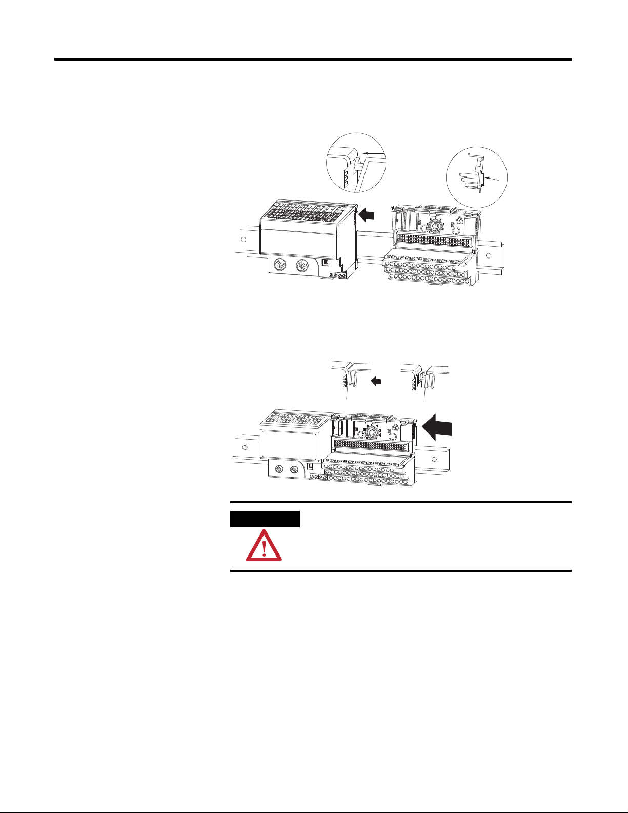
Install the Terminal Base Unit
1. Remove the cover plug in the male connector of the unit to which you
are connecting this terminal base unit.
2. Check to make sure that the 16 pins in the male connector on the
adjacent device are straight and in line so that the mating female
connector on this terminal base unit will mate correctly.
3. Make certain that the female flexbus connector is fully retracted into
the base unit.
Publication 1794-UM065B-EN-E - September 2010
Page 29
Install Your FLEX I/O Analog Modules 17
ATTENTION
A
A
41106
41107
4. Position the terminal base at a slight angle and hooked over the top of
the 35 x 7.5mm DIN rail A
(Allen Bradley part number 199-DR1)
5. Slide the terminal base over tight against the adapter (or proceeding
terminal base). Make sure the hook on the terminal base slides under the
edge of the adapter (or proceeding terminal base) and the FLEXbus
connector is fully retracted.
Do not force the terminal base into the adjacent modules. Forcing the
units together can bend or break the hook and allow the units to
separate and break communication over the backplane.
6. Rotate the terminal base onto the DIN rail with the top of the rail
hooked under the lip on the rear of the terminal base.
Use caution to make sure that the female flexbus connector does
not strike any of the pins in the mating male connector.
Publication 1794-UM065B-EN-E - September 2010
Page 30
18 Install Your FLEX I/O Analog Modules
41108
41109
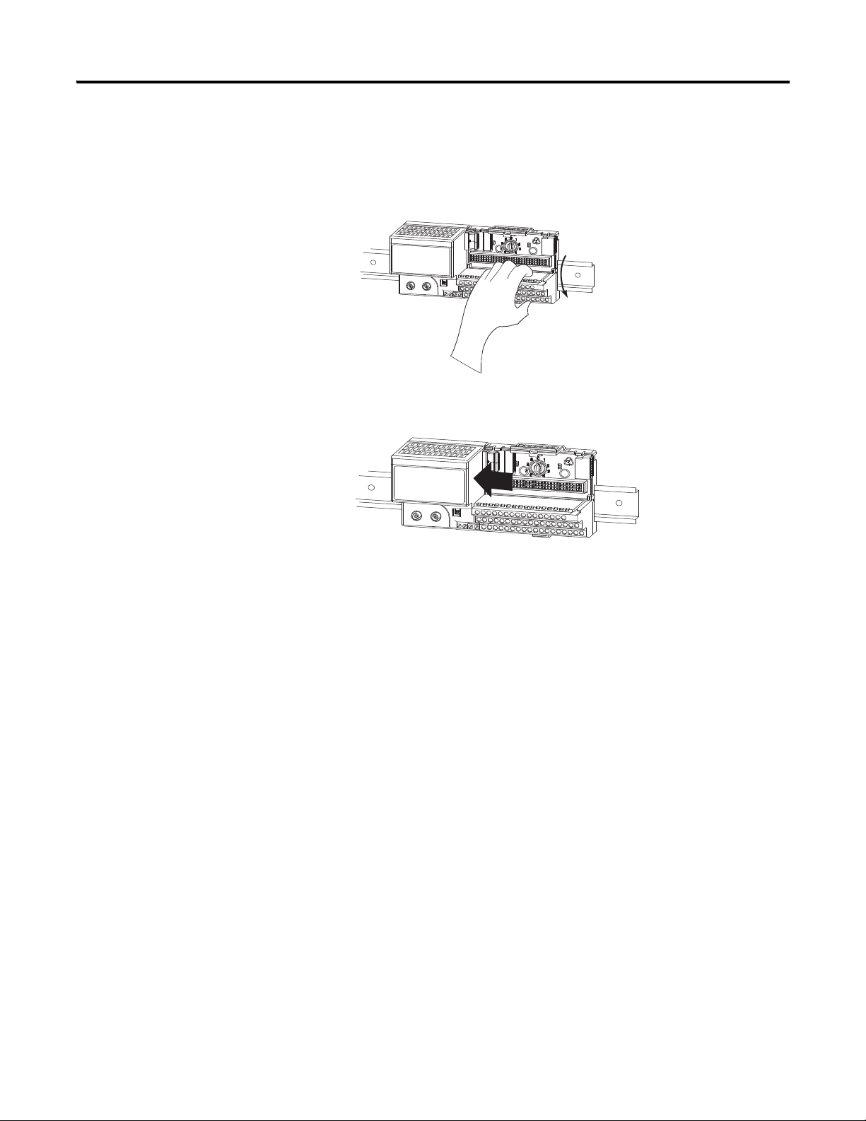
7. Press down on the terminal base unit to lock the terminal base on the
DIN rail. If the terminal base does not lock into place, use a screwdriver
or similar device to open the locking tab, press down on the terminal
base until flush with the DIN rail and release the locking tab to lock the
base in place.
Gently push the Flexbus connector into the side of the adapter (or
proceeding terminal base) to complete the backplane connection.
8. For specific wiring information, refer to the installation instructions for
the module you are installing in this terminal base unit.
Terminal assignments are also given later in this chapter, see page 22.
9. Repeat the above steps to install the next terminal base unit.
Be sure the Flexbus connector cover on the last terminal base unit is in
place.
Mount on a Panel or Wall
Installation of a FLEX I/O system on a wall or panel consists of:
• laying out the drilling points on the wall or panel.
• drilling the pilot holes for the mounting screws.
• mounting the adapter mounting plate.
• installing the terminal base units and securing them to the wall or panel.
If you are installing your module into a terminal base unit that is already
installed, proceed to Mount the Analog Modules on the Terminal Base Unit on
page 21.
Publication 1794-UM065B-EN-E - September 2010
Page 31

Install Your FLEX I/O Analog Modules 19
4
1
2
(35.5)
1.4
41547
3
35.5
(1.4)
15.6
(0.61)
58.5
(2.3)
40.5
(1.6)
8 (0.3)
35.5
(1.4)
58.5
(2.3)
35.5
(1.4)
0.83 (21)
50
(2.0)
Measurements are in mm (in.)
40871
TIP
Use the mounting kit Cat. No. 1794-NM1 for panel/wall mounting.
Description Description
1 Mounting plate for adapter 3 Terminal base unit (not included)
2 #6 Self-tapping screws 4 Adapter module (not included)
To install the mounting plate on a wall or panel:
1. Lay out the required points on the wall/panel as shown in the drilling
dimension drawing.
Cable is either 292.1 mm (11.5 in.) or 901.0 mm (35.5 in.) from upper
connector — depending if you use 0.3 m (1 ft) or 0.91 m (3 ft) cable.
Publication 1794-UM065B-EN-E - September 2010
Page 32

20 Install Your FLEX I/O Analog Modules
ATTENTION
IMPORTANT
Be careful of metal chips when drilling cable mounting holes.
Do not drill holes above a system that has any modules installed.
2. Drill the necessary holes for the #6 self-tapping mounting screws.
3. Mount the mounting plate for the adapter module using two #6
self-tapping screws (18 included for mounting up to 8 modules and the
adapter).
Make certain that the mounting plate is properly grounded to
the panel. Refer to Industrial Automation Wiring and Grounding
Guidelines, publication 1770-4.1
.
4. Hold the adapter at a slight angle and engage the top of the mounting
plate in the indention on the rear of the adapter module.
5. Press the adapter down flush with the panel until the locking lever locks.
6. Position the terminal base unit up against the adapter and push the
female bus connector into the adapter.
7. Secure to the wall with two #6 self-tapping screws.
8. Repeat for each remaining terminal base unit.
Publication 1794-UM065B-EN-E - September 2010
Page 33

Install Your FLEX I/O Analog Modules 21
3
2
4
5
6
1
8
7
Label here
40231
or under here
Mount the Analog Modules on the Terminal Base Unit
The HART analog input and output modules mounts on a 1794-TB3 or 1794-TB3S terminal base unit.
1. Rotate keyswitch on terminal base unit clockwise to position 3 for the
1794-IF8IH or position 4 for the 1794-OF8IH as required for each type
of module.
Do not change the position of the keyswitch after wiring the terminal
base unit.
Description Description
1 FLEXbus connector 5 Base unit
2 Latching mechanism 6 Alignment groove
3 Keyswitch 7 Alignment bar
4 Cap plub 8 Module
2. Make certain the Flexbus connector is pushed all the way to the left to
connect with the neighboring terminal base/adapter.
You cannot install the module unless the connector is fully extended.
3. Make sure the pins on the bottom of the module are straight so they will
align properly with the connector in the terminal base unit.
4. Position the module with its alignment bar aligned with the groove on
the terminal base.
Publication 1794-UM065B-EN-E - September 2010
Page 34

22 Install Your FLEX I/O Analog Modules
41307
IMPORTANT
ATTENTION
IMPORTANT
5. Press firmly and evenly to seat the module in the terminal base unit.
The module is seated when the latching mechanism is locked into the
module.
6. Remove cap plug and attach another terminal base unit to the right of
this terminal base unit if required.
Make sure the last terminal base has the cap plug in place.
The adapter is capable of addressing eight modules. Do not
exceed a maximum of eight terminal base units in your system.
Wire the Terminal Base
Wiring the FLEX I/O HART analog input modules is done using the
1794-TB3 or the 1794-TB3S terminal base unit.
Units
Connect Wiring to the FLEX
Each 1794-IF8IH input can be operated from an analog field device signal,
and each 1794-OF8IH output channel can operate an analog field device.
I/O HART Analog Modules
The FLEX I/O analog modules do not receive primary operational
power from the backplane. +24V DC power must be applied to your
module before operation. If power is not applied, the module position
will appear to the adapter as an empty slot in your chassis. If the
adapter does not recognize your module after installation is
completed, cycle power to the adapter.
When interconnecting several lines, you must consider the total
accumulated power.
Publication 1794-UM065B-EN-E - September 2010
Page 35

Install Your FLEX I/O Analog Modules 23
ATTENTION
0 1 2 3 4 5 6 7 8 9 10 11 12 13 14 15
18 19 20 21 22 23 3324 25 26 27 28 29 30 31 3217
35 36 37 38 47 48 49 5034
51
16
39 40 41 42 43 44 45 46
44319
Row A
Row B
Row C
Row B
Row C
Row A
1794-TB3S shown
Label placed at top of wiring area
Current
input
Current
input
Current
input
AC or DC
four-wire
current
transmitter
DC only
three-wire
current
transmitter
DC only
two-wire
current
transmitter
Connections for the 1794-IF8IH HART Analog Input Module on a 1794-TB3
Terminal Base Unit
Do not use the unused terminals on the terminal base unit. Using
these terminals as supporting terminals can result in damage to the
module and/or unintended operation of your system.
Publication 1794-UM065B-EN-E - September 2010
Page 36

24 Install Your FLEX I/O Analog Modules
ATTENTION
44319x
Row A
Row B
Row C
Row B
Row C
Row A
1794-TB3S shown
Label placed at top of wiring area
Actuator Actuator
Actuator
IN0 IN1 IN2 IN3
8 CH HART ISOLATED ANALOG INPUT
1794-xx8iH
I/O
IN4 IN5 IN6 IN7
PWR
3
44398
Connections for the 1794-OF8IH HART Analog Output Module on a 1794-TB3 or 1794-TB3S Terminal Base Unit
0 1 2 3 4 5 6 7 8 9 10 11 12 13 14 15
16
18 19 20 21 22 23 3324 25 26 27 28 29 30 31 3217
35 36 37 38 47 48 49 5034
39 40 41 42 43 44 45 46
Do not use the unused terminals on the terminal base unit. Using
these terminals as supporting terminals can result in damage to the
module and/or unintended operation of your system.
51
Ground the Module
Chapter Summary
In this chapter, we told you how to install your input module in an existing
programmable controller system and how to wire to the terminal base units.
Go to the next chapter to learn about input, output and configuration files for
HART analog I/O modules on ControlNet and EtherNet networks.
Publication 1794-UM065B-EN-E - September 2010
Page 37

Chapter
IMPORTANT
Input, Output and Configuration of the
FLEX I/O HART Analog I/O Modules
4
Overview
Read this chapter to familiarize yourself with input, output and configuration
files for analog I/O modules on the ControlNet or EtherNet network.
Topic Page
Use Programming Software in Your FLEX I/O Application 25
About the ControlNet and EtherNet Adapters 26
Communication Over the FLEX I/O Backplane 26
I/O Structure 28
Fault State Data 28
Device Actions 28
Chapter Summary 29
In this chapter, you will learn about:
• using software to configure the FLEX I/O modules.
• the ControlNet and EtherNet adapter.
•I/O structure.
• fault state data.
• communication fault data.
• idle state behavior.
• input data behavior upon module removal.
Use Programming Software in Your FLEX I/O Application
25 Publication 1794-UM065B-EN-E - September 2010
This chapter provides a brief description of the steps you must
take in your programming software to configure FLEX I/O
modules and an overview of what occurs during configuration.
For a full explanation of how to use your programming software
to perform module configuration, use the software online help.
When using FLEX I/O analog modules, you must perform I/O mapping and
configure the ControlNet network before generating configuration data for
your I/O modules.
For example, you may use RSNetWorx software to connect FLEX I/O
modules to a ControlNet processor or scanner through a FLEX I/O
Page 38

26 Input, Output and Configuration of the FLEX I/O HART Analog I/O Modules
IMPORTANT
ControlNet adapter (cat. no. 1794-ACNR15). The I/O configuration portion
of another programming software, for example RSLogix5 software, could be
used to generate the configuration data for each I/O module in the control
system.
Configuration data is transferred from the controller to the I/O modules
when communication to the modules is first established.
Follow these general guidelines when configuring I/O modules.
1. Perform I/O mapping.
2. Configure all I/O modules.
3. Change to Run mode to initiate communication.
4. Download module configuration.
About the ControlNet and EtherNet Adapters
Communication Over the FLEX I/O Backplane
The FLEX I/O ControlNet and EtherNet adapter interfaces up to 8
FLEX I/O modules to a ControlNet processor or scanner. The adapter can
support ControlNet real-time data connections to individual modules or
module groups. Each connection is independent of the others and can be from
different processors or scanners.
The FLEX HART modules utilize cyclic extended data transfer
(CEDT) for configuration and data management. Your adapter
must support the CEDT functionality to fully take advantage of
the modules data.
Make sure your ControlNet adapter firmware supports the
cyclic EDT functionality (Version 5 or greater), and that your
EtherNet adapter firmware is Version 4.2 or greater. If using
RSLogix 5000 software, you must use V17 or later.
One adapter can interface up to eight terminal base units with installed
FLEX I/O modules, forming a FLEX I/O system of up to eight slots.
The adapter communicates to other network system components (typically
one or more controllers, scanners, or programming terminals) over the
network. The adapter communicates with its I/O modules over the
FLEX I/O backplane.
Publication 1794-UM065B-EN-E - September 2010
Page 39

Input, Output and Configuration of the FLEX I/O HART Analog I/O Modules 27
I/O Module I/O ModuleI/O Module
Configuration Configuration Configuration
Inputs Inputs Inputs
Status
Outputs
StatusStatus
OutputsOutputs
Read
Words
Write
Words
0
X
Slot 0 Slot 1 Slot 7
Network
Network
Adapter
Read
Write
Configuration data is not continuously updated to the module.
Scheduled Data Transfer
Scheduled data transfer:
• is continuous.
• is asynchronous to the controller program scan.
• occurs at the actual rate displayed in the Actual Packet Interval field on
the programming software ControlNet I/O mapping (monitor) screen.
Unscheduled Data Transfer
Unscheduled operations include:
• unscheduled nondiscrete I/O data transfers – through ControlNet I/O
Transfer (CIO) instructions.
• peer-to-peer messaging–through message (MSG) instructions.
• messaging from programming devices.
Unscheduled messaging on a network is nondeterministic. Your application
and your configuration (for example, number of nodes, application program,
NUT, and amount of scheduled bandwidth used), determine how much time
there is for unscheduled messaging.
Module I/O Mapping
The I/O map for a module is divided into read words and write words. Read
words consist of input and status words, and write words consist of output and
Publication 1794-UM065B-EN-E - September 2010
Page 40

28 Input, Output and Configuration of the FLEX I/O HART Analog I/O Modules
configuration words. The number of read words or write words can be 0 or
more.
The length of each I/O module’s read words and write words vary in size
depending on module complexity. Each I/O module will support at least 1
input word or 1 output word. Status and configuration are optional, depending
on the module.
I/O Structure
Fault State Data
Device Actions
Output data is received by the adapter in the order of the installed I/O
modules. The output data for slot 0 is received first, followed by the output
data for slot 1, and so on up to slot 7.
Input data is sent by the adapter. The first word is the Adapter status word.
This is followed by the input data from each slot, in the order of the installed
I/O modules. The input data from slot 0 is first after the status word, followed
by input data from slot 1, and so on up to slot 7.
The FLEX I/O HART modules provides storage for alternate module output
data during communication faults or processor idle state. This fault state data
assures that a known output will be applied to the output devices during the
previously mentioned modes.
The processor or scanner software must include the means to specify this fault
state data for each module. If applicable, this data is sent in the configuration
block, see page 13.
Device actions include:
Publication 1794-UM065B-EN-E - September 2010
• Communication fault behavior
• Idle state behavior
• Input data behavior upon module removal
Communication Fault Behavior
You can configure the response to a communication fault for each I/O
module in its system. Upon detection of a communication fault, the module
can:
• Leave the module output data in its last state (hold last state)
• Reset the module output data to zero (reset)
• Apply fault state data to the module output
Page 41

Input, Output and Configuration of the FLEX I/O HART Analog I/O Modules 29
Idle State Behavior
The FLEX I/O HART module can detect the state of the controlling
processor or scanner. Only 2 states can be detected: Run mode, or Program
mode (idle).
When Run mode is detected, the adapter copies the output data received from
the processor to the corresponding module output. When Program mode is
detected, the I/O module can be configured to:
• Leave the module output data in its last state (hold last state)
• Reset the module output data to zero (reset)
• Apply fault state data to the module output
Chapter Summary
In this chapter you learned about input, output and configuration files for the
analog I/O modules on ControlNet or EtherNet networks.
Publication 1794-UM065B-EN-E - September 2010
Page 42

30 Input, Output and Configuration of the FLEX I/O HART Analog I/O Modules
Notes:
Publication 1794-UM065B-EN-E - September 2010
Page 43

Chapter
5
1794-IF8IH and 1794-OF8IH Configuration
Overview
This chapter explains how to configure your FLEX I/O module. Use RSLogix
programming software to install and configure your HART module. This
chapter describes how to configure your HART analog I/O modules, but is
limited to a relatively brief explanation of how to use the software. For more
information on the full capabilities of the software, see the software's online
help by clicking Help from dialogs.
See the table for a list of where to find specific information in this chapter.
Topic Page
Data Transfer Types 31
Real Time Data (RTD) Profile, Primary Input Parameters 45
Real Time Data (RTD) Profile, Primary Status Parameters 46
Secondary Input Data Table, Cyclic EDT Input Data 52
Interpret the Status Indicators 57
Module Configuration for the 1794-OF8IH 57
Real Time Data (RTD) Profile, Status Parameters 70
Real Time Data (RTD) Profile, Output Parameters 73
Secondary Input Data Table, Cyclic EDT Input Data 75
Status Indicators 75
Chapter Summary 76
Data Transfer Types
31 Publication 1794-UM065B-EN-E - September 2010
The module will make use of three data transfer modes that will be supported
by the FLEX I/O Adapter.
The first mode is traditional real time data transfer called Cyclic Data Transfer
(CDT). This class 1 connection transfers a continuous block of 16 words
maximum, composed of Input, Output, and Configuration registers. CDT will
be used for standard Analog data transfers and is described in 1794-IF8IH
I/O Profile and Configuration Parameters below.
The second mode of data transfer makes use of the Cyclic EDT mode. Cyclic
EDT will be used for continuous Class 1 transfer of HART data. This includes
the first four dynamic HART Data variables, along with standard HART status
information.
Page 44

32 1794-IF8IH and 1794-OF8IH Configuration
1794-IF8IH I/O Profile
All Allen Bradley FLEX I/O modules have a sixteen word table of Real Time
Data (RTD) to be transferred between the controller and the I/O module.
Not all 16 words need be allocated. The IF8IH has the following RTD IO
Profile:
RTD Index Assembly/Index Asembly
RTD 0 MSW Module Status Word
RTD 1 EDT Read Word EDT Read Word
RTD 2…9 I:0…I:7 RTD Input Data
RTD 10…14 S:0…14 RTD Input Data
RTD 15 EDT Write Word EDT Write Word
In addition to the RTD, the module uses EDT for Configuration and HART
data. The IF8IH has the following EDT IO Profile:
Nunmber of Word EDT Assembly
42 EDT Configuration Data
98 Cyclic EDT HART Input Data (Accessed in eight 24 byte Assemblies)
48 EDT Output Pass-Through message request buffer A
48 EDT Output Pass-Through message request buffer B
48 EDT Input Pass-Through message request buffer A
48 EDT Input Pass-Through message request buffer B
Configuration Parameters
The configuration is shown in the table below. These are normal module
configuration items and are sent to the module. Configuration is located at
EDT assembly 37.
Configuration Parameters
Word Bit
1514131211109876543210
0 R R F7F6F5F4
1 DH7 DH6 DH5 DH4 DH3DH2 DH1 DH0
BOB
(1)
RRF3F2F1F0
Reserved
(2)
BOA
(1)
2 CH 3 Format CH 2 Format CH 1 Format CH 0 Format
3 CH 7 Format CH 6 Format CH 5 Format CH 4 Format
4 CH1 HART Current Ratio FLTR1 CH0 HART Current Ratio FLTR0
Publication 1794-UM065B-EN-E - September 2010
Page 45

1794-IF8IH and 1794-OF8IH Configuration 33
Configuration Parameters
Word Bit
1514131211109876543210
5 CH3 HART Current Ratio FLTR3 CH2 HART Current Ratio FLTR2
6 CH5 HART Current Ratio FLTR5 CH4 HART Current Ratio FLTR4
7 CH7 HART Current Ratio FLTR7 CH6 HART Current Ratio FLTR6
8 Reserved
9 CH0 High Alarm threshold
10 CH0 Low Alarm threshold
11 CH0 Remote High High Alarm Limit
12 CH0 Remote Low Low Alarm Limit
13…16 Words 9…12 for Channel 1
17…20 Words 9…12 for Channel 2
21…24 Words 9…12 for Channel 3
25…28 Words 9…12 for Channel 4
29…32 Words 9…12 for Channel 5
33…36 Words 9…12 for Channel 6
37…40 Words 9…12 for Channel 7
41 Reserved C7 C6 C5 C4 C3 C2 C1 C0
(1)
not shown or used in RSLogix 5000.
(2)
reserved data may not be shown in certain controller software
Configuration Map Descriptions
BOA
BOB
Byte order group A
Byte order group B
Byte order group A and B values must match each other.
Refer to the Byte Order table on page 37.
FLTRn Channel n Digital Filter Refer to 1794-IF8IH Channel Digital Filter table
Fn Fault mode channel n 0: Local/Remote faults disabled 1: Enabled
CHn HART
Current Ratio
HART current fault ratio limit on
channel n
Valid values are 0, or 5…31 percent of full scale. A value of 0 disables this
feature. Refer to the 1794-IF8IH HART Current Ratio table on page 34 for more
information.
DHn Disable HART communications on
0: HART communications enabled 1: HART communications disabled
channel n
Cn HART CMD 3 Disable 0: HART CMD 3 communications
enabled
1: HART CMD 3 communications
disabled
R Reserved
CH N Format Refer to the 1794-IF8IH Channel Data Formats table on page 34.
Publication 1794-UM065B-EN-E - September 2010
Page 46

34 1794-IF8IH and 1794-OF8IH Configuration
1794-IF8IH Channel Data Formats
Format
(1)
Bits Format Name Signal Range User Range Resolution
15 14 13 12
11 10 9 8
7654 LO HI LO HI
3210
0 00000…20 mA in Milliamps 0.00 22.00 0 (0.000 mA) 22000 (22.000 mA) 1.0 µA
1 00010…20 mA in % Full Scale0.00 22.00 0 (0%) 11000 (110.00%) 2.0 µA
3 00110…20 mA in UINT 0.00 20.00 0 65535 0.3052 µA
(2)
4
(2)
5
(2)
7
(1)
All other formats are invalid.
(2)
HART Communications supported with these data formats only.
01004…20 mA in Milliamps 2.00 22.00 2000 (2.000 mA) 22000 (22.000 mA) 1.0 µA
01014…20 mA in % Full Scale2.00 22.00 -1250 (-12.50%) 11250 (112.50%) 1.6 µA
01114…20 mA in UINT 4.00 20.00 0 65535 0.2441 µA
1794-IF8IH Channel Digital Filter
Digital Filter frequency Decimal
Value
Bits
10 9 8
210
470 Hz 0 0 0 0
62 Hz 1 0 0 1
19.6 Hz 2 0 1 0
16.7 Hz 3 0 1 1
10 Hz 4 1 0 0
4.17 Hz 5 1 0 1
Not applicable 6 1 1 0
Not applicable 7 1 1 1
1794-IF8IH HART Current Ratio
HART Current
Ratio Limit
Decimal
Value
Bits
15 14 13 12 11
76543
Disabled 0 0 0 0 0 0
Not applicable 1 0 0 0 0 1
Not applicable 2 0 0 0 1 0
Not applicable 3 0 0 0 1 1
Not applicable 4 0 0 1 0 0
Publication 1794-UM065B-EN-E - September 2010
5% 5 00101
Page 47

IMPORTANT
1794-IF8IH HART Current Ratio
1794-IF8IH and 1794-OF8IH Configuration 35
HART Current
Ratio Limit
6% 6 00110
7% 7 00111
8% 8 01000
9% 9 01001
10% 10 0 1 0 1 0
… … ……………
30% 30 1 1 1 1 0
31% 31 1 1 1 1 1
Decimal
Value
Bits
15 14 13 12 11
76543
Byte Order (2 of 2 bits)
This setting selects the byte order of module's data. Note: The MSW and EDT
words (Words 0, 1 and 15) of the Primary Input Data Table are not swapped.
All other Primary Input Data and Configuration Data are adjusted according
to the following chart
Byte Order
Byte Order
Group B
Bit 9 Bit 8 Bit 1 Bit 0 Description
0 0 0 0 Little Endian Format (default) — all data entries in true
1 0 1 0 Word Swap — word swap only values requiring more
0 1 0 1 Byte Swap — byte swap all words in data table.
1 1 1 1 Big Endian Format — all data entries in true Big Endian
Byte Order
Group A
Little Endian format
than one word, for example, 32 bit float values.
format.
Byte Order can not be changed using RSLogix 5000 software.
RSLogix 5000 uses the default Byte Swap setting.
The purpose of this parameter is to allow this module to operate properly
within data networks or systems utilizing various byte orders, across all data
types (for example, Boolean data to 32 bit float data). Upon receiving the
configuration assembly the module must inspect BYTE ORDER to determine
how to interpret the configuration assembly.
Two sets of Byte Order bits are provided since the module will not know at
power-up and configuration reception what Endian format the configuration
Publication 1794-UM065B-EN-E - September 2010
Page 48

36 1794-IF8IH and 1794-OF8IH Configuration
data being received is in. No matter what the format, two bit sets will always
convey correct information to the module. Both sets must match each other
for the module to accept the configuration and begin processing it for
operation. If the two sets do not match, the module will revert to the last valid
configuration (in case of original start-up this would be default configuration)
and set module Diagnostic Status to 2, configuration failure.
Reasoning for this configuration parameter: Within the CIP based Rockwell
Automation (RA) control system all data is transported and utilized in Little
Endian format. As such the default mode of operation for these modules will
be Little Endian.
Since these modules are HART modules, and HART data is normally provided
in Big Endian format, the module will be responsible for converting any
HART in Big Endian format into Little Endian format.
Additionally, partners provide ProfiBus scanners and adapters for the RA
system. ProfiBus operates in Big Endian format.
For FLEX I/O and FLEX Ex I/O: The Logix scanner byte swaps on word
boundaries, based on the GSD configuration data for a FLEX transfer. The
FLEX adapter byte swaps on word boundaries, based on the GSD
configuration data.
The test shows this to be true, that is, Little Endian data from the
FLEX backplane gets byte swapped on word boundaries onto the wire, but
ends up being back in Little Endian on Logix memory.
If a user utilized ProfiBus and Logix with these new FLEX I/O modules
having 32 bit REAL values he would leave the BYTE ORDER parameter at
default. The Logix scanner byte swaps on word boundaries, based on the GSD
configuration data for a FLEX transfer. The FLEX I/O adapter byte swaps on
word boundaries, based on the GSD configuration data. True little Endian
REAL data from the FLEX I/O backplane gets byte swapped on word
boundaries onto the wire, but ends up being back in little Endian on Logix
memory.
If a user utilized ProfiBus with these new FLEX I/O modules having 32 bit
REAL values he would set the BYTE ORDER parameter at WORD SWAP.
The scanner would read the data off the wire. The FLEX I/O module would
word swap the REAL values. The FLEX I/O adapter byte swaps on word
boundaries, based on the GSD configuration data. True little Endian REAL
data from the modules gets word swapped onto the FLEX I/O backplane gets
byte swapped on word boundaries onto the wire, and ends up in big Endian
format in memory.
Publication 1794-UM065B-EN-E - September 2010
Page 49

1794-IF8IH and 1794-OF8IH Configuration 37
Examples
In each of the following examples, the module operates internally with little
Endian byte order.
Little Endian BYTE ORDER
If BYTE ORDER indicates Little Endian, utilize the configuration assembly
directly.
Partial Configuration Assembly as Received
Partial Configuration Assembly after BYTE ORDER Inspection and Processing
1 Param A Ch2 Param B Ch2 Param A Ch1 Param B Ch1
2 Param C CH0 (2nd byte) Param C CH0 (low byte)
3 Param C CH0 (high byte) Param C CH0 (3rd byte)
1 Param A Ch2 Param B Ch2 Param A Ch1 Param B Ch1
2 Param C CH0 (2nd byte) Param C CH0 (low byte)
3 Param C CH0 (high byte) Param C CH0 (3rd byte)
Provide all data to the Primary Data table in Little Endian byte order.
The following two tables are an example of the Primary Input Data, if BYTE
ORDER indicated Little Endian.
Primary Input Data Before BYTE ORDER Processing for Little Endian
1 Ch2 Data A (REAL) (2nd byte) Ch2 Data A (REAL) (low byte)
2 Ch2 Data A (REAL) (high byte) Ch2 Data A (REAL) (3rd byte)
3 Ch2 Data C Ch2 Data B
Primary Input Data After BYTE ORDER Processing for Little Endian
1 Ch2 Data A (REAL) (2nd byte) Ch2 Data A (REAL) (low byte)
2 Ch2 Data A (REAL) (high byte) Ch2 Data A (REAL) (3rd byte)
3 Ch2 Data C Ch 2 Data B
Publication 1794-UM065B-EN-E - September 2010
Page 50

38 1794-IF8IH and 1794-OF8IH Configuration
Word Swap BYTE ORDER
If BYTE ORDER indicates Word Swap, utilize the known structure of the
configuration assembly to re-order multi-word data elements to Little Endian
byte order, for example, word swap FLOATS).
Partial Configuration Assembly as Received
1 Param A Ch2 Param B Ch2 Param A Ch1 Param B Ch1
2 Param C CH0 (high byte) Param C CH0 (3rd byte)
3 Param C CH0 (2nd byte) Param C CH0 (low byte)
Partial Configuration Assembly after BYTE ORDER Inspection and Processing
1 Param A Ch2 Param B Ch2 Param A Ch1 Param B Ch1
2 Param C CH0 (2nd byte) Param C CH0 (low byte)
3 Param C CH0 (high byte) Param C CH0 (3rd byte)
Provide all data to the Primary Data table in Word Swap byte order, except the
MSW and EDT words (Words 0, 1 and 15), these remain in Little Endian byte
order.
The following tables are an example of the Primary Input Data, if BYTE
ORDER indicated Word Swap.
Primary Input Data Before BYTE ORDER Processing for Little Endian
1 Ch2 Data A (REAL) (2nd byte) Ch2 Data A (REAL) (low byte)
2 Ch2 Data A (REAL) (high byte) Ch2 Data A (REAL) (3rd byte)
3 Ch2 Data C Ch 2 Data B
Primary Input Data After BYTE ORDER Processing for Little Endian
1 Ch2 Data A (REAL) (high byte) Ch2 Data A (REAL) (3rd byte)
2 Ch2 Data A (REAL) (2nd byte) Ch2 Data A (REAL) (low byte)
3 Ch2 Data C Ch 2 Data B
Fault Mode (8 of 1 bit)
Selects whether the channel fault detection for Local and Remote Alarms is
enabled or disabled. This does not disable High and Low Alarms.
Publication 1794-UM065B-EN-E - September 2010
Range: 0=disable, 1=fault detection enabled (remote transmitter loop, wire off
and overload or short circuit)
Default: 0
Data Table Reference: fault mod, Configuration Word 0, Bits 2…5 and
10…13.
Page 51

Accuracy vs Filter Cutoff
1794-IF8IH and 1794-OF8IH Configuration 39
Input Filter Cutoff (8 of 3 bits)
ADC Filter Frequency for channel. This parameter affects channel accuracy:
See the table below.
Data Table Reference: filter cutoff, Configuration Words 4…7, bits 0…2,
8…10.
Filter Cutoff
Frequency n/a n/a 470 Hz 62 Hz 19.6 Hz 16.7 hz 10 Hz 4.17 Hz
Word Setting n/a n/a 101 100 011 010 001 000
(1)
For settings of 6 & 7 the module will return a configuration error and remain in the last properly configured state.
(1)
7
(1)
6
543210 (Default)
ADC Conversion Rate, Channel Update Time and Repeatability
The following table shows the channel update time, channel settling time,
repeatability, 50 Hz normal mode rejection and 60 Hz normal mode rejection
for each A/D conversion rate. The repeatability is based on six-sigma RMS
noise levels.
ADC Conversion Rate Effects
A/D
Conversion
Rate
4.17 Hz 240 msec 480 msec 0.12 μa 74 dB 74 dB
10.0 Hz 100 msec 200 msec 0.23 μa 69 dB 69 dB
16.7 Hz 60 msec 120 msec 0.31 μa 80 dB
Channel
Update
Time
Channel
Settling
Tim e
Repeatability 50 Hz
Rejection
60 Hz
Rejection
19.6 Hz 51 msec 101 msec 0.35 μa 90 dB
62 Hz 16 msec 32 msec 0.59 μa
470 Hz 2 msec 4 msec 2.27 μa
Data Format (8 of 4 bits)
Specifies the module data format. Formats 2, 6 and 8…15 are not assigned. If
they are selected, a configuration failure will be declared. The configuration is
not accepted and the last valid configuration will be used.
Formats 5, 12, 13 and 14 are 2's complement data formats, and will return data
in that form.
Publication 1794-UM065B-EN-E - September 2010
Page 52

40 1794-IF8IH and 1794-OF8IH Configuration
Datatable = 10000
input
(
20
)
Datatable = 65535
input
(
20
)
1794-IF8IH Data Formats
Alarms are adjustable with Formats 0-7. See Data Formats and Error Ranges.
Alarms are preset/fixed with Formats 8-15. See Data Formats and Error
Ranges.
Range: 0…15, See 1794-IF8IH Data Formats on page 40
Default: 0
Data Table Reference: data format, Configuration Words 2 and 3, bits 0…3,
4…7, 8…11, 12…15.
Data
Format
0 0…20 mA
1 0…20 mA
2 Not Assigned
3 0…20 mA
4 4…20 mA
Format Resolution Input Range Module Data Processing Data Table Value
as mA
as %
as unsigned
integer
as mA
0.1% of
0…20 mA
0.2% of
0…20 mA
0.03% of
0…20 mA
0.1% of
4…20 mA
(Interpretation)
0…22 mA Datatable = 1000 (input) 0…22000
(0…22.000 mA)
0…22 mA 0…11000
(0…110.00%)
0…20 mA 0…65535
(0…20 mA)
2…22 mA Datatable = 1000 (input) 2000…22000
(2.000…22.000
mA)
Count per mA/
Resolution
1000/
1.0 µA
500/2.0 µA
3276/
0.3052 µA
1000/
1.0 µA
Publication 1794-UM065B-EN-E - September 2010
Page 53

1794-IF8IH Data Formats
Datatable = 10000
input-4
(
16
)
Datatable = 65535
input-4
(
16
)
1794-IF8IH and 1794-OF8IH Configuration 41
Data
Format
5 4…20 mA
6 Not Assigned
7 4…20 mA
8 0…20 mA Not Assigned
9 0…20 mA Not Assigned
10 0…20 mA Not Assigned
11 0…20 mA Not Assigned
12 4…20 mA Not Assigned
13 4…20 mA Not Assigned
14 4…20 mA Not Assigned
15 4…20 mA Not Assigned
Format Resolution Input Range Module Data Processing Data Table Value
0.16% of
as %
as unsigned
integer
4…20 mA
0.03% of
4…20 mA
(Interpretation)
2…22 mA -1250 … +11250
( 2’s c om pl em en t)
(-12.50% …
+112.50%)
4…20 mA 0…65535
(4…20 mA)
Count per mA/
Resolution
625/
1.6 µA
4095/
0.2441 µA
Remote Low Low Alarm Limit (8 of 16 bit)
Sets the limit for the Remote Fault Low Low Alarm in 1 μA steps. This affects
Data Formats 0…7. Steps apply to the 4…20 mA range.
For example, a value of 3600 will cause a Remote Fault Low Low Alarm below
3.6 mA (3600*1 μA=3.6 mA).
Range: 0…22000 (0=disabled, 1*1 μA to 22000*1 μA)
Default: 0=disabled
Data Table Reference: Remote Low Low Alarm Limit, Configuration Words
12, 16, 20, 24, 28, 32, 36 and 40, bits 0…15
Publication 1794-UM065B-EN-E - September 2010
Page 54

42 1794-IF8IH and 1794-OF8IH Configuration
44780
Data Formats and Error Ranges
Remote High High Alarm Limit (8 of 16 bit)
Sets the limit for the Remote Fault High High Alarm in 1 μA steps. This
affects Data Formats 0…7. Steps apply to the 4…20 mA range and 0…20 mA
range.
For example, a value of 20400 will cause a Remote Fault High High Alarm
above 20.4 mA (20400*1 μA = 20.4 mA).
Range: 0…22000 (0=disabled, 1*1 μA to 22000*1 μA)
Default: 0=disabled
Data Table Reference: Remote High High Alarm Limit, Configuration Words
11, 15, 19, 23, 27, 31, 35 and 39, bits 0…15
Low Alarm Limit (8 of 16 bit)
Sets the limit for the Low Alarm in 1 μA steps. This affects Data Formats
0…7. Steps apply to the 4-20 mA range.
For example, a value of 4000 will cause an Low Alarm below 4.0 mA (4000*1
μA = 4 mA).
Publication 1794-UM065B-EN-E - September 2010
Range: 0…22000 (0=disabled, 1*1 μA to 22000*1 μA)
Default: 0=disabled
Data Table Reference: Low Alarm Limit, Configuration Words 10, 14, 18, 22,
26, 30, 34 and 38, bits 0…15
Page 55

1794-IF8IH and 1794-OF8IH Configuration 43
High Alarm Limit (8 of 16 Bit)
Sets the limit for the High Alarm in 1 μA steps. This affects Data Formats
0…7. Steps apply to the 4-20 mA range and 0…20 mA range.
For example, a value of 20000 will cause an High Alarm above 20.0 mA
(20000*1 μA = 20 mA).
Range: 0…22000 (0=disabled, 1*1 μA to 22000*1 μA)
Default: 0=disabled
Data Table Reference: High Alarm Limit, Configuration Words 9, 13, 17, 21,
25, 29, 33 and 37, bits 0…15
HART Disable Channel 0 to 7 (8 of 1 bit)
When this bit is set, the I/O module is inhibiting its HART Communication.
Range: 0= enable, 1= disable
Default: 0
Data Table Reference: HART DISABLE, Configuration Word 1 bits 8…15
HART Current Fault Limit (8 of 5 bits)
Delivers the percentage value (in steps of 1%, starting @ 5%) of the threshold
for causing a HART current fault indication (input signal deviation HART/
Analog) = 31% maximum deviation.
If there is no HART transmitter on the loop or the loop is not in the
transmitter list the function is switched off internally in the I/O module.
Range: 0=disabled, 1…4= not supported by the I/O module. A configuration
request of 1…4 will cause a value of 5 to be utilized by the module. 5…31=
percentage threshold data (5…31%).
Default: 0
Command 3 Disable (8 of 1 bit)
This bit disables the I/O channel from forwarding the associated HART
Command 3 information from the HART Field device through Cyclic EDT to
the adapter.
Publication 1794-UM065B-EN-E - September 2010
Page 56

44 1794-IF8IH and 1794-OF8IH Configuration
This does not disable the module from gathering HART Command 3
information from the HART Field device. As such, HART Command 3
information from the HART Field device is still available via an unconnected
message to the module.
When the adapter powers up, it reads each module to find out which modules
are present in the Flexbus. For EDT modules it reads Assembly 125 to gain
knowledge of all the assemblies the module has, whether they are
EDT/CEDT and whether they are GET/SET. If an assembly is a CEDT
assembly, the adapter automatically creates a CEDT entry and drops it into the
EDT machine to gather/send this assembly and store the assembly locally in
the adapter. Sometime later a ForwardOpen configuration arrives by the
network for the module. The adapter proxy strips off a portion (Configuation
Part 1) and sends the rest (Configuration Part 2) on through EDT to the
module. Within this module configuration part are the CMD3 Disable Chx
bits. These bits instruct the module to include or not include CMD3 scanning
in the work for the channel. Users may not have HART devices on every
channel so some channels may want CMD3 disabled. If scanning is disabled,
the module also disables the adapter from including that particular associated
assembly in the CEDT scanning routine by the method described below.
The module uses the CMD3 Disable Chx bits to adjust the CEDT entries in
Assembly 125. Initially the Assembly 125 CEDT assemblies (46-53) are
identified as CEDT (0xC0 Cyclic EDT Get or 0x40 Cyclic EDT Set). This
causes the adapter to add them to the CEDT scan. If the module receives a
configuration with CMD3 Disable CHx bits set to "1" (disable), the module
changes the appropriate channel's Assembly 125 entry from 0xC0 Cyclic EDT
Get to 0x80 EDT Get or 0x40 Cyclic EDT Set to 0x00 EDT Set.
Whenever the adapter receives a ForwardOpen to an EDT module, the
adapter automatically rereads the module's Assembly 125 to gain a new view of
the assemblies. This reread is to check for any changes of CEDT Assemby
status to EDT status. If a CMD3 Disable Chx was received on any particular
channel, now the previous CEDT assembly is marked as an EDT assembly
and the adapter will not add that assembly to his CEDT scan. This
ForwardOpen reread will happen any time a module receives a ForwardOpen,
including a Null-ForwardOpen received during system runtime.
Range: 0 = enabled, 1 = disabled
Default: 0
Publication 1794-UM065B-EN-E - September 2010
Page 57

1794-IF8IH and 1794-OF8IH Configuration 45
Real Time Data (RTD) Profile, Primary Input Parameters
Input Map
Word Bit
15 14 13 12 11 10 9 8 7 6 5 4 3 2 1 0
0 Channel 0 Input Data
1 Channel 1 Input Data
2 Channel 2 Input Data
3 Channel 3 Input Data
4 Channel 4 Input Data
5 Channel 5 Input Data
6 Channel 6 Input Data
7 Channel 7 Input Data
8 H7H6 H5H4H3H2H1H0L7 L6 L5 L4 L3 L2 L1 L0
9 R7R6 R5R4R3R2R1R0P7 P6P5P4 P3P2P1 P0
10
11 C7 C6 C5 C4 C3 C2 C1 C0 F7 F6 F5 F4 F3 F2 F1 F0
12 X7 X6 X5 X4 X3 X2 X1 X0 Reserved
Where: Hn: Channel n High Alarm
Ln : Channel n Low Alarm
Rn : Channel n Out of Range Alarm
Pn : Channel n Second (Remote) Alarm
Fn : Channel n HART Failure
Cn : Channel n HART Current Fault
Xn : Channel n HART Transmitter Present
Primary Input Data (8 of 16 bits each)
Specifies the value of the input data from the module. Specific format is
controlled by module Data Format Control parameter.
Range: Refer to Data Format (8 of 4 bits) on page 39.
Data Table Reference: input data, Input Words 0…7 (I0…I7), bits 0…15.
Publication 1794-UM065B-EN-E - September 2010
Page 58

46 1794-IF8IH and 1794-OF8IH Configuration
Real Time Data (RTD) Profile, Primary Status Parameters
Alarms
This module is capable of generating four different alarms; low, high, remote
and loop alarm. The diagram below graphically shows at what values these
alarms are generated for Data Format 5.
Alarm Operation
In this example the normal active data range is 4…20 mA. The alarms will be
generated in three overlapping bands. Looking at the high end of the range
first:
If the input signal exceeds the High Alarm Limit a High Alarm is generated.
This alarm stays active at any value above the High Alarm Limit. The High
Alarm Limit parameter allows you to program this threshold in 1 μA steps at
any level from 0.0mA to 22 mA. For this data format this would indicate -25%
to 112.50% of range. In practice this is meant to be used as a High Alarm, set
from 20.001 mA to 22 mA (for this data format this is 100.0063% to 112.50%
of range), as example.
If the input signal exceeds the Remote High High Alarm Limit the Remote
Alarm is issued. This alarm stays active at any value above the Remote High
High Alarm Limit. The Remote High High Alarm Limit parameter allows you
to program this threshold in 1 μA steps at any level from 0.0 mA to 22 mA.
For this data format this would indicate -25% to 112.50% of range. In practice
this is meant to be used as a High High Alarm, set from 20.001 mA to 22 mA
(for this data format this is 100.0063% to 112.50% of range), as example.
If the input continues to climb the Loop Alarm will be issued at 22 mA
(112.50% of range). Again, as with the High Alarm and Remote Alarm, when
the Loop Alarm is issued, it stays active at any value above 22 mA (112.50% of
range).
Similarly, looking at the low end of the range:
If the input signal falls below the Low Alarm Limit an Low Alarm is
generated. This alarm stays active at any value below the Low Alarm Limit.
The Low Alarm Limit parameter allows you to program this threshold in 1 μA
steps at any level from 0.0 mA to 22 mA. For this data format this would
indicate -25% to 112.50% of range. In practice this is meant to be used as a
Low Alarm, set from 3.999 mA to 2 mA (for this data format this is -0.0063%
to -12.50% of range), as example.
If the input signal falls below the Remote Low Low Alarm Limit the Remote
Alarm is issued. This alarm stays active at any value below the Remote Low
Low Alarm Limit. The Remote Low Low Alarm Limit parameter allows you to
program this threshold in 1 μA steps at any level from 0.0 mA to 22 mA. For
this data format this would indicate -25% to 112.50% of range. In practice this
Publication 1794-UM065B-EN-E - September 2010
Page 59

1794-IF8IH and 1794-OF8IH Configuration 47
0 mA
Loop
Alarm
-25.00 % -12.50 %
Remote Alarm
programmable
in 1 μA steps
by Remote
Low Low
Alarm Limit
parameter
programmable
in 1 μA steps by
Low Alarm
Limit parameter
0.00 %
Low Alarm
4 mA 20 mA
Normal Signal Range
100.00 %
programmable
in 1 μA steps by
High Alarm
Limit parameter
programmable
in 1 μA steps
by Remote
High High
Alarm Limit
parameter
112.50 %
High Alarm
Remote Alarm
Loop
Alarm
22 mA
PHYSICAL INPUT SIGNLA RANGE
45152
Format 5
is meant to be used as a Low Low Alarm, set from 3.999 mA to 2 mA (for this
data format this is -0.0063% to -12.50% of range), as an example.
If the input continues to fall the Loop Alarm is issued at 2 mA (-12.50%).
Again, as with the Low Alarm and Remote Alarm, when the Loop Alarm is
issued, it stays active at any value below 2 mA (-12.50% of range).
Data Format 5 Alarm Example, Series B
Data Formats 8…11 do not issue Low or Remote Alarms due to input low
conditions, since the normal input range includes 0 mA, and these Data
Formats have pre-programmed fault levels, see Data Formats and Error
Ranges on page 42.
The Remote and Loop Alarms are issued with the same bit whether the cause
is an under or overrange. Just looking at these bits will not indicate if the fault
is from a too low or too high input. The High Alarm and Low Alarm bits
should be monitored to determine which way the reading is moving. By
programmatically combining High, Low and Remote Alarm bits, Low Low,
Low, High and High High Alarms can be generated.
Another use of these alarms and thresholds is to accommodate transmitters
which sense faults in the remote loop and give a drastic under or overrange
indication to the local loop when the fault occurs. By appropriately setting the
Remote High High or Remote Low Low Alarm Limit parameters and
monitoring the Remote Alarm bit.
When active, these alarms trigger at set currents. Depending on Data Format,
these current values may indicate percent, mA or integer values.
The Remote Alarm and Loop Alarm may be disabled by the Fault Mode bit.
The High Alarm is active for Data Formats 0-7, unless disabled by a "0"
(default) value of High Alarm Limit. The High Alarm is always active for Data
Publication 1794-UM065B-EN-E - September 2010
Page 60

48 1794-IF8IH and 1794-OF8IH Configuration
Formats 8…15, with pre-programmed fault levels, see Data Formats and
Error Ranges on page 42.
The Low Alarm is active for Data Formats 0…7, unless disabled by a "0"
(default) value of Low Alarm Limit. The Low Alarm is not available for Data
Formats 8…11, since the normal input range includes 0 mA. The Low Alarm
is always active for Data Formats 12…15, with pre-programmed fault levels,
see Data Formats and Error Ranges on page 42.
These alarm types are meant to accommodate traditional direct measurement
loops and loops incorporating remote transmitters.
See to Data Format (8 of 4 bits) on page 39 and 1794-IF8IH Data Formats on
page 40 for specific explanations of Data Formats, and Remote Low Low
Alarm Limit (8 of 16 bit) on page 41, Remote High High Alarm Limit (8 of 16
bit) on page 42, Low Alarm Limit (8 of 16 bit) on page 42, High Alarm Limit
(8 of 16 Bit) on page 43 and Data Formats and Error Ranges on page 42 for
specific explanations of Error Ranges.
High Alarm (8 of 1 bit each)
Alarm signal for input overrange.
For Data Formats 0…7, alarm thresholds are adjustable by the High Alarm
Limit parameter. This signal is active, unless disabled by a "0" (default) value of
High Alarm Limit.
For Data Formats 8…15, alarm thresholds are preset. This signal is always
active.
Range: 0=normal, 1=input overrange
Data Table Reference: high alarm, Status Word 0, bits 8…15
Low Alarm (8 of 1 bit each)
Alarm signal for input underrange.
For Data Formats 0…7, alarm thresholds are adjustable by the Low Alarm
Limit parameter. This signal is active, unless disabled by a "0" (default) value of
Low Alarm Limit.
Data Formats 8…11 do not issue Low Alarm due to input low conditions,
since the normal input range includes 0 mA.
For Data Formats 12…15, alarm thresholds are preset. This signal is always
active.
Publication 1794-UM065B-EN-E - September 2010
Range: 0=normal, 1=input underrange
Data Table Reference: Low Alarm, Status Word 0, bits 0…7
Page 61

1794-IF8IH and 1794-OF8IH Configuration 49
Remote Alarm (8 of 1 bit each)
Alarm from remote transmitter, indicating transmitter difficulties, sensor
difficulties or loop to the sensor is open. If no transmitter is present this alarm
can be utilized as a Low Low and/or High High Alarm. This is accomplished
programmatically by "ANDing" together the Remote Alarm and the Low
Alarm for a Low Low Alarm and the Remote Alarm and the High Alarm for a
High High Alarm.
This alarm is active for both a high indication and low indication.
Alarm thresholds are adjustable by the Remote High High and Remote Low
Low Alarm Limit parameters for Data Formats 0…7.
Alarm thresholds are preset for Data Formats 8…15.
Range: 0=normal, 1=fault detected
Data Table Reference: rem alarm, Status Word 1, bits 8…15
Loop Alarm (8 of 1 bit each)
Alarm indicating the loop to the transmitter, or, if there is no transmitter, the
loop is open or shorted. When active, this alarm triggers at 2 mA and 22 mA
for open and short respectively.
Range: 0=normal, 1=fault detected.
Data Table Reference: local fault, Status Word 1, bits 0…7
Module Diagnostic Status (1 of 8 bits)
Response from module on its condition.
Diagnostic Status Value: 0 Channel Failure
0x00 All No Errors (default)
0x10 Channel 0 HART Iloop Threshold Configuration Error
0x11 Channel 1 HART Iloop Threshold Configuration Error
0x12 Channel 2 HART Iloop Threshold Configuration Error
0x13 Channel 3 HART Iloop Threshold Configuration Error
0x14 Channel 4 HART Iloop Threshold Configuration Error
0x15 Channel 5 HART Iloop Threshold Configuration Error
0x16 Channel 6 HART Iloop Threshold Configuration Error
0x17 Channel 7 HART Iloop Threshold Configuration Error
0x20 Channel 0 Remote/Local Alarm Configuration Error
Publication 1794-UM065B-EN-E - September 2010
Page 62

50 1794-IF8IH and 1794-OF8IH Configuration
Diagnostic Status Value: 0 Channel Failure
0x21 Channel 1 Remote/Local Alarm Configuration Error
0x22 Channel 2 Remote/Local Alarm Configuration Error
0x23 Channel 3 Remote/Local Alarm Configuration Error
0x24 Channel 4 Remote/Local Alarm Configuration Error
0x25 Channel 5 Remote/Local Alarm Configuration Error
0x26 Channel 6 Remote/Local Alarm Configuration Error
0x27 Channel 7 Remote/Local Alarm Configuration Error
0x30 Channel 0 Over/Under Alarm Configuration Error
0x31 Channel 1 Over/Under Alarm Configuration Error
0x32 Channel 2 Over/Under Alarm Configuration Error
0x33 Channel 3 Over/Under Alarm Configuration Error
0x34 Channel 4 Over/Under Alarm Configuration Error
0x35 Channel 5 Over/Under Alarm Configuration Error
0x36 Channel 6 Over/Under Alarm Configuration Error
0x37 Channel 7 Over/Under Alarm Configuration Error
0x40 Channel 0 Format Configuration Error
0x41 Channel 1 Format Configuration Error
0x42 Channel 2 Format Configuration Error
0x43 Channel 3 Format Configuration Error
0x44 Channel 4 Format Configuration Error
0x45 Channel 5 Format Configuration Error
0x46 Channel 6 Format Configuration Error
0x47 Channel 7 Format Configuration Error
0x50 Channel 0 ADC Filter Configuration Error
0x51 Channel 1 ADC Filter Configuration Error
0x52 Channel 2 ADC Filter Configuration Error
0x53 Channel 3 ADC Filter Configuration Error
0x54 Channel 4 ADC Filter Configuration Error
0x55 Channel 5 ADC Filter Configuration Error
0x56 Channel 6 ADC Filter Configuration Error
0x57 Channel 7 ADC Filter Configuration Error
0x80 Module Hardware Failure
0x90 Channel 0 Calibration Error
0x91 Channel 1 Calibration Error
0x92 Channel 2 Calibration Error
Publication 1794-UM065B-EN-E - September 2010
0x93 Channel 3 Calibration Error
0x94 Channel 4 Calibration Error
Page 63

1794-IF8IH and 1794-OF8IH Configuration 51
Diagnostic Status Value: 0 Channel Failure
0x95 Channel 5 Calibration Error
0x96 Channel 6 Calibration Error
0x97 Channel 7 Calibration Error
0xA0 Channel 0 Internal Bus Com Error
0xA1 Channel 1 Internal Bus Com Error
0xA2 Channel 2 Internal Bus Com Error
0xA3 Channel 3 Internal Bus Com Error
0xA4 Channel 4 Internal Bus Com Error
0xA5 Channel 5 Internal Bus Com Error
0xA6 Channel 6 Internal Bus Com Error
0xA7 Channel 7 Internal Bus Com Error
HART Status Fields
The 1794-IF8IH supports two connections for pass through messages. Pass
through messages provide a user the ability to send HART messages to the
HART device by passing through the I/O Module. In additional, HART
device information automatically gathered by the I/O module may be accessed
through this interface.
The 1794-IF8IH provides 8 queues for each of the two connections. This
allows each connection to have up to eight messages pending at any given
time, one for each channel. HART pass through message implements a
timeout which is fixed at twenty seconds.
The first connection is provided for a ladder logic user. The following status
bits are provided to simplify ladder logic. The second connection does not
have status bits provided in the RTD. It can obtain this status by implementing
polling messages using the pass through message interface.
HART Failure (8 of 1 bit each)
This bit indicates each time there is a HART communication failure detected,
between the module and the HART field device (HART FD), on the channel.
This failure could be timeout, response checksum, parity, framing, HART FD
disappears, HART FD mismatch (from device detected at last rebuild), for
example. If there is a failure the appropriate channel's bit is set. The bit is not
latched.
Publication 1794-UM065B-EN-E - September 2010
Page 64

52 1794-IF8IH and 1794-OF8IH Configuration
The I/O module performs automatic retries and therefore a user should rarely
recognize communication problems at the protocol layer. Therefore, this flag
can be used to qualify the communication quality.
Range: 0 = no HART failures are detected, 1 = A HART failure is detected
HART Current Fault (8 of 1 bit each)
Alarm signal for HART Current Fault, indicating the HART data value is
outside the HART Current Fault limit percentage. Active when limit is
exceeded. The analog measured current is compared with the digital current
value, read out dynamically via the HART interface. Active when limit is
exceeded. Refer to HART Current Fault Limit (8 of 5 bits) on page 43.
Range: 0 = normal, 1 = fault detected.
Secondary Input Data Table, Cyclic EDT Input Data
HART Transmitter List (8 of 1 bit each)
Indicates a HART transmitter has been detected on this channel, during the
last rebuild.
Range: 0 = A HART Transmitter was not detected, 1 = A HART Transmitter
is detected.
The data in the following table is where the HART protocol device data is
published. The data table is not available as a group in the module. It is formed
in the communication adapter by the Cyclic EDT mechanism (adapter to
module) where the adapter cyclically requests a set of module attributes and
forms this data table.
Additionally, the adapter appends the first two words to indicate
communication status between adapter and module with regard to each of the
cyclic EDT transfers. Two (2) words are provided, for status, as today's
adapters provide for up to 32 items in the CEDT queue.
Publication 1794-UM065B-EN-E - September 2010
Page 65

1794-IF8IH and 1794-OF8IH Configuration 53
For this module the total Secondary Input Data Table (I) Words = 98, as
shown in the HART Input Data table..
HART Input Data
Word Bit
15 14 13 12 11 10 9 8 7 6 5 4 3 2 1 0
0/I Reserved Ch7 Ch6 Ch5 Ch4 Ch3 Ch2 Ch1 Ch0
HART CMD 3 (Communications Status)
1 Reserved
2 Ch0 HART Field Device Status Ch0 HART Comm Status
3 Reserved FVA TVA SVA PVA Ch0 HART Loop Status
4 Ch0 HART Privary Value (IEEE 754-1985 Single-Precision 32 bit floating point)
5
6 Ch0 HART Secondary Value (IEEE 754-1985 Single-Precision 32 bit floating point)
7
8 Ch0 HART Tertiary Value (IEEE 754-1985 Single-Precision 32 bit floating point)
9
10 Ch0 HART Fourth (Quaternary) Value (IEEE 754-1985 Single-Precision 32 bit floating point
11
12 Ch0 SV Units Code Ch0 PV Units Code
13 Ch0 FV Units Code Ch0 TV Units Code
14…25 Words 2…13 for Channel 1
26…37 Words 2…13 for Channel 2
38…49 Words 2…13 for Channel 3
50…61 Words 2…13 for Channel 4
62…73 Words 2…13 for Channel 5
74…85 Words 2…13 for Channel 6
86…97 Words 2…13 for Channel 7
HART Command 3 Communication Status (8 of 1 bits):
These bits indicate status of the CEDT data transfer between the adapter and
the modules. In this module the CEDT attributes transferred are HART
command 3 data for the indicated channel number.
Range: 0 = disabled or no CEDT HART Command 3 Communication error
between the adapter and the I/O module, 1= a CEDT HART Command 3
Communication error between the adapter and the I/O module.
Publication 1794-UM065B-EN-E - September 2010
Page 66

54 1794-IF8IH and 1794-OF8IH Configuration
IMPORTANT
Data Table Reference: CMD3 Comm Status, Secondary Input Word 0
bits 0…7.
HART Field Device Command and Communication Status (8 of 8 bits)
This byte indicates the status of HART FD communication for the channel. It
is the first status byte of the HART response and the FD status, example:
"parity error", "framing error", "invalid selection" or "too few data bytes
received" is coded in.
Data Table Reference: HART Comm Status, Secondary Input Word a,
bits 0…7.
HART Field Device Status (8 of 8 bits)
This byte is part of the CMD 3 data response of the HART FD. It is the
second status byte of the HART response and the FD status, example:
"primary variable out of limits" or "analog output saturated" is coded in.
CMD3 2nd status byte response codes
HART Field Device Status
Bit 0 Primary variable out of limits
Bit 1 Non-primary variable out of limits
Bit 2 Analog output saturated
Bit 3 Analog output current fixed
Bit 4 More status available
Bit 5 Cold start
Bit 6 Configuration changed
Bit 7 Field device malfunction
All bits "0" (when a communication error is reported in the
CMD3 1st status byte)
Data Table Reference: HART Field Device Status, Secondary Input Word a,
bits 8…15.
Publication 1794-UM065B-EN-E - September 2010
Page 67

1794-IF8IH and 1794-OF8IH Configuration 55
HART Loop Status (8 of 8 bits):
This byte indicates the Status of the HART loop from the I/O modules point
of view. This byte is generated by the I/O module itself and not from the
HART FD.
HART Loop Status
HART Loop Status
Bit 0
Bit 1 HCS_CONNECTED, A connection has been established with this device.
Bit 2 HCS_RESPONSE_ERROR, A HART message attempt ended in failure.
Bit 3 HCS_CMD48_UPDATE, Extended HART status (Command 48) was updated.
Bit 4 HCS_ILOOP_TOLERANCE, HART Current Fault loop current fault.
Bit 5 HART_update, The HART Field Device data for the channel has been updated
Bit 6 HART_Message, The channel's HART message queue has completed a message
Bit 7 Reserved
(1)
(1)
HCS_COMM_ENABLED, HART is enabled on this channel.
Range: 0 = HART not enabled on this channel, 1 = HART enabled on this channel
Range: 0 = no HART connection on this channel, 1 = HART connection on this
channel
Range: 0 = no HART message failures, 1 = HART message attempt failed
Range: 0 = extended HART status (Command 48) was not updated, 1 = extended
HART status (Command 48) was updated
Range: 0 = no HART Current Fault loop current fault, 1 = HART Current Fault loop
current fault
since last read.
Range: 0 = no HART FD data update, 1 = new HART FD data available
since request has been received.
Range: 0 = no HART message has completed, 1 = a HART message has completed
HCS — HART Communications State machine
HART PV Status (8 of 8 bits):
This byte indicates the status of the HART variables (primary, secondary, third
and fourth).
HART PV Status
Bit 0 The primary variable for this channel has been acquired.
Bit 1 The secondary variable for this channel has been acquired.
Bit 2 The third variable for this channel has been acquired.
Bit 3 The fourth variable for this channel has been acquired.
Bit 4 Reserved
Publication 1794-UM065B-EN-E - September 2010
Page 68

56 1794-IF8IH and 1794-OF8IH Configuration
HART PV Status
Bit 5 Reserved
Bit 6 Reserved
Bit 7 Reserved
Data Table Reference: HART PV Status, Secondary Input Word b, bits 8…15.
Primary HART Variable (8 of 32 bits):
This is the Primary HART Variable from the field device. Its datatype is REAL
and it is organized according to Byte Order, see Byte Order (2 of 2 bits).
Secondary HART Variable (8 of 32 bits):
This is the Secondary HART Variable from the field device. Its datatype is
REAL and it is organized according to Byte Order, see Byte Order (2 of 2
bits).
Third HART Variable (8 of 32 bits):
This is the Third HART Variable from the field device. Its datatype is REAL
and it is organized according to Byte Order, see Byte Order (2 of 2 bits).
Fourth HART Variable (8 of 32 bits):
This is the Fourth HART Variable from the field device. Its datatype is REAL
and it is organized according to Byte Order, see Byte Order (2 of 2 bits).
Primary HART Variable Units Code (8 of 8 bits):
Publication 1794-UM065B-EN-E - September 2010
This is the units code for the Primary HART Variable.
Secondary HART Variable Units Code (8 of 8 bits):
This is the units code for the Secondary HART Variable.
Page 69

1794-IF8IH and 1794-OF8IH Configuration 57
Third HART Variable Units Code (8 of 8 bits):
This is the units code for the Third HART Variable.
Fourth HART Variable Units Code (8 of 8 bits):
This is the units code for the Fourth HART Variable.
Interpret the Status
The module has a single Red & Green indicator for global module
status/power indication. A single bi-color indicator displays the module status
Indicators
Module Status Indicators
Module
State
New Power up initialized complete and passed Self-Test.
No Config Module has not received configuration from Master.
Idle Controller in Program mode.
Active Controller in Run mode & Communication Is normal 1 1 1 Green, solid
Fault FLEX I/O Comm. Fault or PU bit is one and /Fault=0 * * 0 Green, blink
Fatal fault Module fails self tests or detects illegal state
Off External power has not been applied. Off
(1)
The status bits in the table correspond to module status bits available in the module status word.
(2)
Bit state flagged as '*' depends on the state transition.
Condition PU Bit Prog/Run bit Fault bit LED Color and
Loads stored configuration, if it exists. Read Module
Information Block.
It can Set and Get attributes.
Communications normal
transition
(1)
as indicated below.
State
(2)
*
0 * * Green, blink
1 0 1 Green, blink
* * * Red, solid
* * Red, blink
Module Configuration for the 1794-OF8IH
Output Connections
This module uses the 1794-TB3, Revision B terminal base for full isolation.
Connect the I+ output to the terminal contacts indicated and the
corresponding center return (R) contact. Be sure to observe the polarity
indicated for proper operation. Channels are numbered in order, 0 through 7,
from left to right.
Publication 1794-UM065B-EN-E - September 2010
Page 70

58 1794-IF8IH and 1794-OF8IH Configuration
0-15
16-33
-Vin -V
C O M M O N S
+Vin +V
34-51
A
B
C
10325476981110 1312 1514
2928 3130 33322322 2524 27261716
CH-0
1918 2120
4746 4948 51504140 4342 45443534 3736 3938
CH-1 CH-2 CH-3 CH-4 CH-5 CH-6 CH-7
1794-OF8IH Terminal Base Connections
Connect an external 24 V DC power supply to terminals 34 (V+) and 16 (V-)
observing polarities indicated. Terminals 17 through 33 are internally shorted
to terminal 16. Terminal 51 is internally shorted to terminal 34. Use the DC
output terminals only for low power modules, following FLEX I/O power
connection guidelines.
Please follow wiring instruction for FLEX I/O modules, terminal bases and
racks. Connect the Ground the shield drain wire at one end only. The
preferred/required location is at the sensor end. When connecting the shield
drain at the module end, connect it to earth ground using a panel or DIN rail
mounting screw.
Configuration Parameters
Configuration is shown in two parts in the following. These are normal
module configuration items and are sent to the module.
All configuration parameters are EDT (Extended Data Transfer) WRITE
items.
Configuration is located at EDT assembly 37.
Publication 1794-UM065B-EN-E - September 2010
Page 71

1794-IF8IH and 1794-OF8IH Configuration 59
Analog Output Module (1794-OF8IH)
Configuration Map
Word Bit
1514131211109876543210
0 FT R EW7 EW6 EW5 EW4
BOB
(1)
1 DH7 DH6 DH5 DH4 DH3 DH2 DH1 DH0
R R EW3 EW2 EW1 EW0
Reserved
(2)
BOA
(1)
2 CH 3 Format CH 2 Format CH 1 Format CH 0 Format
3 CH 7 Format CH 6 Format CH 5 Format CH 4 Format
4 CH1 HART Current Ratio L1 AFS1 CH0 HART Current Ratio L0 AFS0
5 CH3 HART Current Ratio L3 AFS3 CH2 HART Current Ratio L2 AFS2
6 CH5 HART Current Ratio L5 AFS5 CH4 HART Current Ratio L4 AFS4
7 CH7 HART Current Ratio L7 AFS7 CH6 HART Current Ratio L6 AFS6
8 DF7 DF6 DF5 DF4 DF3 DF2 DF1 DF0 DM7 DM6 DM5 DM4 DM3 DM2 DM1 DM0
9 Channel 0 Analog Fault Value Output Data
10 Channel 1 Analog Fault Value Output Data
11 Channel 2 Analog Fault Value Output Data
12 Channel 3 Analog Fault Value Output Data
13 Channel 4 Analog Fault Value Output Data
14 Channel 5 Analog Fault Value Output Data
15 Channel 6 Analog Fault Value Output Data
16 Channel 7 Analog Fault Value Output Data
17 Reserved C7 C6 C5 C4 C3 C2 C1 C0
(1)
not shown or used in RSLogix 5000.
(2)
Reserved data may not be shown in certain controller software
1794-OF8IH Channel Data Formats
(1)
Format
Bits Format Name Signal Range User Range Resolution
15 14 13 12
11 10 9 8
7654 LOHI LO HI
3210
0 0 0 0 0 0…20 mA in Milliamps 0.00 22.00 0 (0.000 mA) 22000 (22.000 mA) 1.0 µA
1 0 0 0 1 0…20 mA in % Full Scale 0.00 22.00 0 (0%) 11000 (110.00%) 2.0 µA
3 0 0 1 1 0…20 mA in UINT 0.00 20.00 0 65535 0.3052 µA
Publication 1794-UM065B-EN-E - September 2010
Page 72

60 1794-IF8IH and 1794-OF8IH Configuration
1794-OF8IH Channel Data Formats
(1)
Format
Bits Format Name Signal Range User Range Resolution
15 14 13 12
11 10 9 8
7 6 5 4 LO HI LO HI
3210
(2)
4
(2)
7
(2)
14
(1)
All other formats are invalid.
(2)
HART Communications supported with these data formats only.
0 1 0 0 4…20 mA in Milliamps 2.00 22.00 2000 (2.000 mA) 22000 (22.000 mA) 1.0 µA
0 1 1 1 4…20 mA in UINT 4.00 20.00 0 65535 0.2441 µA
1 1 1 0 4…20 mA in % Full Scale 2.00 22.00 -1250 (-12.50%) 11250 (112.50%) 1.6 µA
1794-OF8IH Channel Analog Fault Mode Selection
Analog Fault Mode Decimal Value Bits
98
10
Min Scale 0 0 0
Max Scale 1 0 0
Hold Last State 2 1 0
User Specifed Data Value 3 1 1
1794-OF8IH HART Current Ratio
HART Current
Ratio Limit
Decimal
Value
Bits
15 14 13 12 11
76543
Disabled 0 00000
Not applicable 1 0 0 0 0 1
Not applicable 2 0 0 0 1 0
Not applicable 3 0 0 0 1 1
Not applicable 4 0 0 1 0 0
5% 5 00101
6% 6 00110
7% 7 00111
8% 8 01000
Publication 1794-UM065B-EN-E - September 2010
9% 9 01001
10% 10 0 1 0 1 0
Page 73

IMPORTANT
1794-OF8IH HART Current Ratio
1794-IF8IH and 1794-OF8IH Configuration 61
HART Current
Ratio Limit
… … ……………
30% 30 1 1 1 1 0
31% 31 1 1 1 1 1
Decimal
Value
Bits
15 14 13 12 11
76543
Byte Order (2 of 2 bits)
Selects the byte order of module's data.
Note: The MSW and EDT words (Words 0, 1 and 15) of the Primary Input
Data Table are not swapped. All other Primary Input Data and Configuration
Data are adjusted according to the following chart:
1794-OF8IH Byte Order Configuration
Byte Order
Group B
Bit 9 Bit 8 Bit 1 Bit 0 Description
0000Little Endian Format (default) — all data entries in
Byte Order
Group A
true Little Endian format
1010Word Swap — word swap only values requiring
more than one word, for example, 32 bit float
values.
0101Byte Swap — byte swap all words in data table.
1111Big Endian Format — all data entries in true Big
Endian format.
Byte Order can not be changed using RSLogix 5000 software.
RSLogix 5000 uses the default Byte Swap setting.
The purpose of this parameter is to allow this module to operate properly
within data networks or systems utilizing various byte orders, across all data
types (e.g. Boolean data to 32 bit float data).
Upon receiving the configuration assembly the module must inspect Byte
Order to determine how to interpret the configuration assembly.
Two sets of Byte Order bits are provided since the module will not know at
power-up and configuration reception what Endian format the configuration
data he is receiving is in. No matter what the format though these two, two bit
sets always convey correct information to the module. Both sets must match
each other for the module to accept the configuration and begin processing it
Publication 1794-UM065B-EN-E - September 2010
Page 74

62 1794-IF8IH and 1794-OF8IH Configuration
for operation. If the two sets do not match the module reverts to the last valid
configuration (in case of original start-up this is the default configuration), set
module Diagnostic Status to "2" configuration failure, set outputs to fault
states and do not start operation.
Reasoning for this configuration parameter:
Within the CIP based Rockwell Automation (RA) control system all data is
transported and utilized in Little Endian format. As such the default mode of
operation for these modules is Little Endian.
Since these modules are HART modules, and HART data is normally provided
in Big Endian format, the module is responsible for converting any HART in
Big Endian format into Little Endian format.
Additionally, partners provide ProfiBus scanners and adapters for the RA
system. ProfiBus operates in Big Endian format.
The test shows this to be true, i.e. little Endian data from the FLEX backplane
gets byte swapped on word boundaries onto the wire, but ends up being back
in little Endian on Logix memory.
If a user utilized ProfiBus and Logix with these new FLEX I/O modules
having 32 bit REAL values he would leave the Byte Order parameter at
default. The Logix scanner byte swaps on word boundaries, based on the GSD
configuration data for a FLEX transfer. The FLEX I/O adapter byte swaps on
word boundaries, based on the GSD configuration data. True little Endian
REAL data from the FLEX backplane gets byte swapped on word boundaries
onto the wire, but ends up being back in little Endian on Logix memory.
If a user utilized ProfiBus with these new FLEX I/O modules having 32 bit
REAL values he would set the Byte Order parameter at Word Swap. The
scanner reads the data off the wire. The FLEX I/O module word swaps the
REAL values. The FLEX I/O adapter byte swaps on word boundaries, based
on the GSD configuration data. True little Endian REAL data from the
modules gets word swapped onto the FLEX backplane gets byte swapped on
word boundaries onto the wire, and ends up in big Endian format in memory.
Examples
In each of the following examples, the module operates internally with little
Endian byte order.
Publication 1794-UM065B-EN-E - September 2010
Page 75

1794-IF8IH and 1794-OF8IH Configuration 63
Little Endian Byte Order
If Byte Order indicates Little Endian, utilize the configuration assembly
directly.
Partial Configuration Assembly as Received
Partial Configuration Assembly after BYTE ORDER Inspection and Processing
Provide all data to the Primary Data table in Little Endian byte order.
The following two tables are an example of the Primary Input Data, if Byte
Order indicated Little Endian.
1 Param A Ch2 Param B Ch2 Param A Ch1 Param B Ch1
2 Param C CH0 (2nd byte) Param C CH0 (low byte)
3 Param C CH0 (high byte) Param C CH0 (3rd byte)
1 Param A Ch2 Param B Ch2 Param A Ch1 Param B Ch1
2 Param C CH0 (2nd byte) Param C CH0 (low byte)
3 Param C CH0 (high byte) Param C CH0 (3rd byte)
Primary Input Data Before BYTE ORDER Processing for Little Endian
1 Ch2 Data A (REAL) (2nd byte) Ch2 Data A (REAL) (low byte)
2 Ch2 Data A (REAL) (high byte) Ch2 Data A (REAL) (3rd byte)
3 Ch2 Data C Ch 2 Data B
Primary Input Data After BYTE ORDER Processing for Little Endian
1 Ch2 Data A (REAL) (2nd byte) Ch2 Data A (REAL) (low byte)
2 Ch2 Data A (REAL) (high byte) Ch2 Data A (REAL) (3rd byte)
3 Ch2 Data C Ch 2 Data B
Word Swap BYTE ORDER
If BYTE ORDER indicates Word Swap, utilize the known structure of the
configuration assembly to re-order multi-word data elements to Little Endian
byte order, for example, word swap FLOATS).
Partial Configuration Assembly as Received
1 Param A Ch2 Param B Ch2 Param A Ch1 Param B Ch1
2 Param C CH0 (high byte) Param C CH0 (3rd byte)
3 Param C CH0 (2nd byte) Param C CH0 (low byte)
Publication 1794-UM065B-EN-E - September 2010
Page 76

64 1794-IF8IH and 1794-OF8IH Configuration
Partial Configuration Assembly After BYTE ORDER Inspection and Processing
1 Param A Ch2 Param B Ch2 Param A Ch1 Param B Ch1
2 Param C CH0 (2nd byte) Param C CH0 (low byte)
3 Param C CH0 (high byte) Param C CH0 (3rd byte)
Provide all data to the Primary Data table in Word Swap byte order, except the
MSW and EDT words (Words 0, 1 and 15), these remain in Little Endian byte
order.
The following tables are an example of the Primary Input Data, if BYTE
ORDER indicated Word Swap.
Primary Input Data Before BYTE ORDER Processing for Little Endian
1 Ch2 Data A (REAL) (2nd byte) Ch2 Data A (REAL) (low byte)
2 Ch2 Data A (REAL) (high byte) Ch2 Data A (REAL) (3rd byte)
3 Ch2 Data C Ch 2 Data B
Primary Input Data After BYTE ORDER Processing for Little Endian
1 Ch2 Data A (REAL) (high byte) Ch2 Data A (REAL) (3rd byte)
2 Ch2 Data A (REAL) (2nd byte) Ch2 Data A (REAL) (low byte)
3 Ch2 Data C Ch 2 Data B
Default: 0
Fault Mode (8 of 1 bit)
Selects whether the channel fault detection is enabled or disabled. There is a
100 ms filter for wire off/lead break and short circuit detection.
Range: 0=Disable, 1= Wire off/ead break and short circuit fault detection
enabled.
Default: 0
Bus Communications and Module Fault Mode (1 of 1 bit)
Publication 1794-UM065B-EN-E - September 2010
This parameter determines how the Module Fault State is used for bus
communication and internal module faults. This parameter sets this
characteristic for the module.
Range: 0=Fault States activated by bus communication faults, 1=Fault States
activated by any failure (bus communications, wire off or short circuit if
detection enabled, for example.)
Page 77

1794-IF8IH and 1794-OF8IH Configuration 65
Default: 0
HART Disable Channel 0 to 7 (8 of 1 bit)
When this bit is set, the I/O module is inhibiting its HART Communication.
Range: 0=Enable, 1=Disable
Default: 0
HART Current Fault Limit (8 of 5 bits)
Delivers the percentage value (in steps of 1%, starting @ 5%) of the threshold
for causing a HART current fault indication (input signal deviation HART/
Analog) = 31% maximum deviation.
If there is no HART transmitter on the loop or the loop is not in the
transmitter list the function is switched off internally in the I/O module.
Range:
0=Disabled,
1…4=Not supported by the I/O module. A configuration request of 1…4
causes a value of 5 to be utilized by the module.
5…31=Percentage threshold data (5…31%)
Default: 0
Analog Data Format (8 of 4 bits each)
Specifies the module data format for a channel. Formats 2, 5, 6, 8, 9, 10, 12
and 15 are not assigned.
If a module channel has never been configured then it can be assumed to have
the default configuration Analog Data Format "0", 0…20mA and Analog
Mode Fault State minimum range. If a non-assigned format is selected, then
the diagnostic "2" for configuration failure is set and the module channel goes
to the default fault state minimum range.
If, on the other hand, the configuration is changed from the default, and then
changed again to a non-assigned format, then the diagnostic bit "2" for
configuration failure is set and the module goes to the fault state for the last
valid configuration.
Formats 13 and 14 are 2's complement data formats, and require data to the
module in that form.
Publication 1794-UM065B-EN-E - September 2010
Page 78

66 1794-IF8IH and 1794-OF8IH Configuration
Output =
datatable
(
1000
)
Output = 20
datatable
(
10000
)
Output = 20
datatable
(
65535
)
Output =
datatable
(
1000
)
Output = 16
datatable
(
65535
)
+ 4
Output = 16
datatable
(
10000
)
+ 4
1794-OF8IH Data Formats
Range: 0…15. Refer to the 1794-OF8IH Data Formats table.
Data
Format
0 (default) mA as
1 % as
2 0…20 mA — 0…22 mA Not Assigned
3 Unsigned
4 mA as
5 4…20 mA — 4…20 mA Not assigned
6 4…20 mA 4…20 mA Not assigned
7 Unsigned
8 0…20 mA 0…20 mA Not assigned
9 0…20 mA 0…20 mA Not assigned
10 0…20 mA 0…20 mA Not assigned
11 0…20 mA 0…20 mA Not assigned
12 4…20 mA Not assigned
13 4…20 mA Not assigned
14 % as
15 4…20 mA 4…20 mA Not assigned
Format Resolution Full
Output
Range
0…20 mA
0…20 mA
integer as
0…20 mA
4…20 mA
integer as
4…20 mA
4…20 mA
0.1% of
0…20 mA
0.2% of
0…20 mA
0.03% of
0…20 mA
0.1% of
4…20 mA
0.03% of
4…20 mA
0.16% of
4…20 mA
0…22 mA 0…22000
0…22 mA 0…11000
0…20 mA 0…65535
2…22 mA 2000…22000
4…20 mA 0…65535
2…22 mA -1250 … +11250
Module Data Processing Data Table Value
(Interpretation)
(0…22.000 mA)
(0…110.00%)
(0…20 mA)
(2.000…22.000
mA)
(4…20 mA)
( 2 ’ s c o m p l e m e n t )
(-12.50% …
+112.50%)
Count per
mA/
Resolution
1000/
1.0 µA
500/
2.0 µA
3276/
0.305 µA
1000/
1.0 µA
4095/
0.244 µA
625/
1.6 µA
Analog Fault
State
Min=0 mA
Max=22 mA
hold
Last=hold
FS value
Min=0 mA
Max=22 mA
hold
Last=hold
FS value
Min=0 mA
Max=20 mA
hold
Last=hold
FS value
Min=2 mA
Max=22 mA
hold
Last=hold
FS value
Min=4 mA
Max=20 mA
hold
Last=hold
FS value
Min=2 mA
Max=22 mA
hold
Last=hold
FS value
Publication 1794-UM065B-EN-E - September 2010
If data is sent to the module which is out of range, the value is clipped and
Diagnostic Data is set to "11" data out of range. To view a graphical
representation of this performance, see the example on page 12.
Page 79

1794-IF8IH and 1794-OF8IH Configuration 67
Reset
Hold Last
MIN Range
MAX Range
Hold Last
Fault State Value
Normal State
Value
Fault State
Value
Fault
Latch
Mode
100 ms
Filter
Blink
Timer
Reset
Output Mode
(Analog/Digital)
45287
FAULT_ALARM_0
FAULT_LED_0
CHANNEL_0
GLOBAL_RESET
LATCH_MODE_0
FAULT_MODE_0
SHRT_CRKT_0
LB_0
LOCAL_FAULT_MODE_0
PROG/RUN (EDT word Bit 15)
FAULT (EDT word Bit 14)
BUS_COM_FAULT, other internal module faults
ANALOG_DIGITAL_MODE_0
ANALOG_FAULT_STATE_0
DIGITAL_FAULT_STATE_0
OUT_0
ANALOG_FAULT_STATE_VALUE_0
Latch Mode (8 of 1 bit each)
Latch Mode determines channel operation under wire off/lead break fault
conditions. Channel fault detection occurs on a continuous basis. If a fault is
detected, the channel fault alarm is set (if Fault Mode is enabled).
If latch is ON the fault is latched until a Global Reset is issued at which time
the fault is reset.
If latch is OFF the channel reports the fault until the fault is corrected. Upon
correction the fault is reset.
Range: 0=OFF, 1=ON
Default: 0
Analog/Digital Output Normal and Fault State Operation
Analog/Digital Output Mode (8 of 1 bit each)
Selects if the channel acts as a normal analog output or as a switched digital
output.
Publication 1794-UM065B-EN-E - September 2010
Page 80

68 1794-IF8IH and 1794-OF8IH Configuration
Analog Output Mode will follow the Analog Data Format selected.
Digital Output Mode will output 0 mA = OFF, 22 mA = ON if the Fault
Mode is 0 = Disable. Digital Output Mode will output 500 µA = OFF, 22 mA
= ON if the Fault Mode is 1 = Wire off fault detection enable.
Range: 0=Normal analog output, 1=Switched digital output
Default: 0
Analog Mode Fault State (8 of 2 bits each)
Determines how module reacts to faults when channel is used in analog
normal mode.
Range: 0=Go to minimum value of Full Output Range, 1=Go to maximum
value of Full Output Range, 2=Hold last state, 3=Use channel fault state
values given in Words 10…17.
Default: 0
Analog Mode Channel Fault State Value (8 of 16 bits each)
This parameter specifies the fault state value of the analog output data for the
channel. Specific format is controlled by Analog Data Format Control
parameter, see Analog Data Format (8 of 4 bits each) on page 65.
This data is used when the channel is in analog output mode.
Examples
If you choose format 2 and set the fault state value to 11000 (accordingly
110.00%), the I/O module provides 22 mA in case of fault state.
If you choose format 7 and set the fault state value to 32000, the I/O module
provides 11.813 mA in case of fault state.
The fault state value is treated in the same way as the normal output value is
treated. So you do not need to recalculate the current when you are used to
work in a special format.
Publication 1794-UM065B-EN-E - September 2010
Range: See Analog Data Format (8 of 4 bits each) on page 65.
Default: 0
Page 81

1794-IF8IH and 1794-OF8IH Configuration 69
Digital Mode Fault State (8 of 1 bit each)
Determines how module reacts to faults when channel is used in digital mode.
Range: 0=Reset, 1=Hold Last State
Default: 0
Command 3 Disable (8 of 1 bit)
This bit disables the I/O channel from forwarding the associated HART
Command 3 information from the HART Field device through Cyclic EDT to
the adapter.
This does not disable the module from gathering HART Command 3
information from the HART Field device. As such, HART Command 3
information from the HART Field device is still available via an unconnected
message to the module.
This feature should be exercised by using a Null ForwardOpen method in the
Logix system. That is, the connection to the module and original configuration
has already been accomplished. If utilized, Command 3 Disable should be
utilized under program control (change bit in module configuration tag then
issue reconfiguration message to module) or, more unusually, a manual
operation by an operator (open module profile, change parameter then apply).
When the adapter powers up it reads each module to find out who is out there.
For EDT modules it reads Assembly 125 to gain knowledge of all the
assemblies the module has, whether they are EDT/CEDT and whether they
are GET/SET. If an assembly is a CEDT assembly, the adapter automatically
creates a CEDT entry and drops it into his EDT machine to gather/send this
assembly and store the assembly locally in the adpater. Sometime later a
ForwardOpen configuration arrives by the network for the module. The
adapter proxy strips off a portion (Configuation Part 1) and sends the rest
(Configuration Part 2) on through EDT to the module. Within this module
configuration part are the CMD3 Disable Chx bits. These bits instruct the
module to include or not include CMD3 scanning in its work for the channel.
Users may not have HART devices on every channel so some channels may
want CMD3 disabled. If users do disable scaning, the module also disables the
adapter from including that particular associated assembly in the CEDT
scanning routine by the following method:
The module uses the CMD3 Disable Chx bits to adjust the CEDT entries in
Assembly 125. Initially the Assembly 125 CEDT assemblies (46-53) are
identified as CEDT (0xC0 Cyclic EDT Get or 0x40 Cyclic EDT Set) this
causes the adapter to add them to the CEDT scan. If the module receives a
configuration with CMD3 Disable CHx bits set to "1" (disable), the module
Publication 1794-UM065B-EN-E - September 2010
Page 82

70 1794-IF8IH and 1794-OF8IH Configuration
Real Time Data (RTD) Profile, Status Parameters
changes the appropriate channel's Assembly 125 entry from 0xC0 Cyclic EDT
Get to 0x80 EDT Get or 0x40 Cyclic EDT Set to 0x00 EDT Set.
Whenever the adapter receives a ForwardOpen to an EDT module, the
adapter automatically rereads the module's Assembly 125 to gain a new view of
the assemblies. This reread is to check for any changes of CEDT Assemby
status to EDT status. If a CMD3 Disable Chx is received on any particular
channel, now the previous CEDT assembly is marked as an EDT assembly
and the adapter does not add that assembly to the CEDT scan. This
ForwardOpen reread happens any time a module receives a ForwardOpen,
including a Null-ForwardOpen received during system runtime.
Range: 0=Enabled, 1=Disabled
Default: 0
1794-OF8IH Primary Data Table
Word/S
ISOC
0/MSW Read RealT Bus Fail Bits # # Words to Read Module ID/Type
1/EDT Read RealT PU/
2/S0 Read RealT F7 F6 F5 F4 F3 F2 F1 F0 Diagnostic status
3/S1 Read RealT Reserved
4/S2 Read RealT C7 C6 C5 C4‘ C3 C2 C1 C0 Reserved
5/S3 Read RealT X7 X6 X5 X4 X3 X2 X1 X0 Reserved
6/EDT Write RealT Prog
7/O0 Read RealT Rese
8/O1 Write RealT Output Data Channel 0
9/O2 Read RealT Output Data Channel 1
10/O3 Read RealT Output Data Channel 2
11/O4 Read RealT Output Data Channel 3
Read/
Write
Data
Transport
Bit
1514131211109876543210
Event
Reserved Read Write SeqCount EDT Data Byte from Module
Cfg
Pdg
Fault Reserved Read Write SeqCount EDT Data Byte from Module
/Run
Globa
Reservd D7D6D5D4D3D2D1D0
rved
l
reset
12/O5 Read RealT Output Data Channel 4
13/O6 Read RealT Output Data Channel 5
Publication 1794-UM065B-EN-E - September 2010
Page 83

1794-OF8IH Primary Data Table
1794-IF8IH and 1794-OF8IH Configuration 71
Word/S
ISOC
14/O7 Read RealT Output Data Channel 6
15/EDT Read RealT Output Data Channel 7
Where: Fn : Channel n Fault alarm
Read/
Write
Cn : Channel n HART Current Fault
Xn : HART Transmitter List
Dn : Channel n Digital out
Data
Transport
Bit
15 14 13 12 11 10 9 8 7 6 5 4 3 2 1 0
Fault Alarm (8 of 1 bit each)
Alarm signal for open wire channel fault, detected at <2 mA (<500 µA in
digital mode) and short circuit (R<42 in the 4…20 mA range, <86 in digital
mode, channel off).
This alarm is disabled when a data format is selected which includes 0 mA.
Range: 0=Normal, 1=Wire off/short circuit fault detected
Default: 0
Diagnostic Data (1 of 8 bits)
Response from module as to its condition.
Diagnostic Status Value: 0 Channel Failure
0x00 All No Errors (default)
0x10 Channel 0 HART Iloop Threshold Configuration Error
0x11 Channel 1 HART Iloop Threshold Configuration Error
0x12 Channel 2 HART Iloop Threshold Configuration Error
0x13 Channel 3 HART Iloop Threshold Configuration Error
0x14 Channel 4 HART Iloop Threshold Configuration Error
0x15 Channel 5 HART Iloop Threshold Configuration Error
0x16 Channel 6 HART Iloop Threshold Configuration Error
0x17 Channel 7 HART Iloop Threshold Configuration Error
0x40 Channel 0 Format Configuration Error
0x41 Channel 1 Format Configuration Error
0x42 Channel 2 Format Configuration Error
0x43 Channel 3 Format Configuration Error
Publication 1794-UM065B-EN-E - September 2010
Page 84

72 1794-IF8IH and 1794-OF8IH Configuration
Diagnostic Status Value: 0 Channel Failure
0x44 Channel 4 Format Configuration Error
0x45 Channel 5 Format Configuration Error
0x46 Channel 6 Format Configuration Error
0x47 Channel 7 Format Configuration Error
0x50 Channel 0 Data out of range
0x51 Channel 1 Data out of range
0x52 Channel 2 Data out of range
0x53 Channel 3 Data out of range
0x54 Channel 4 Data out of range
0x55 Channel 5 Data out of range
0x56 Channel 6 Data out of range
0x57 Channel 7 Data out of range
0x80 Module Hardware Failure
0x90 Channel 0 Calibration Error
0x91 Channel 1 Calibration Error
0x92 Channel 2 Calibration Error
0x93 Channel 3 Calibration Error
0x94 Channel 4 Calibration Error
0x95 Channel 5 Calibration Error
0x96 Channel 6 Calibration Error
0x97 Channel 7 Calibration Error
0xA0 Channel 0 Internal Bus Com Error
0xA1 Channel 1 Internal Bus Com Error
0xA2 Channel 2 Internal Bus Com Error
0xA3 Channel 3 Internal Bus Com Error
0xA4 Channel 4 Internal Bus Com Error
0xA5 Channel 5 Internal Bus Com Error
0xA6 Channel 6 Internal Bus Com Error
0xA7 Channel 7 Internal Bus Com Error
HART Status Fields
Publication 1794-UM065B-EN-E - September 2010
The 1794-OF8IH module supports two connections for pass through
messages. Pass through messages provide the ability to send HART messages
to the HART device by passing through the I/O Module. In additional, HART
device information automatically gathered by the I/O module may be accessed
through this interface.
Page 85

1794-IF8IH and 1794-OF8IH Configuration 73
The 1794-OF8IH module provides 8 queues for each of the two connections.
This allows each connection to have up to 8 messages pending at any given
time, one for each channel. HART pass through message implements a
timeout which is fixed at 20 seconds.
The first connection is provided for a ladder logic user. The following status
bits are provided to simplify ladder logic. The second connection does not
have status bits provided in the RTD. It can obtain this status by implementing
polling messages using the pass through message interface.
HART Current Fault (8 of 1 bit each)
Alarm signal for HART Current Fault, indicating the HART data value is
outside the HART Current Fault limit percentage. Active when limit is
exceeded. The analog measured current is compared with the digital current
value, read out dynamically via the HART interface. Active when limit is
exceeded. See HART Current Fault Limit (8 of 5 bits) on page 65.
Real Time Data (RTD) Profile, Output Parameters
Range: 0=Normal, 1=Fault detected
HART Transmitter List (8 of 1 bit each)
Indicates a HART transmitter has been detected on this channel, during the
last rebuild.
Range: 0=A HART Transmitter was not detected, 1=A HART Transmitter
was detected.
Analog Output Data (8 of 16 bits each)
Specifies the value of the analog output data to the module. Specific format is
controlled by Module Data Format Control parameter. This data is used when
the channel is in analog output mode.
Range: See Analog Data Format (8 of 4 bits each) on page 65.
Digital Output Data (8 of 1 bit each)
Specifies the value of the digital output data to the module. This data is used
when the channel is in digital output mode.
Publication 1794-UM065B-EN-E - September 2010
Page 86

74 1794-IF8IH and 1794-OF8IH Configuration
Range:
If the Fault Mode is 0=Disable: 0=Output 0 mA = OFF, 1=22 mA = ON.
If the Fault Mode is 1=Wire off fault detection enabled: 0=Output
500 µA=OFF, 1=22 mA=ON.
See Analog/Digital Output Mode (8 of 1 bit each) on page 67.
Global Reset (1 of 1 bit)
This bit resets all latched fault alarms. It acts in conjunction with the Latch
Retry parameter. If any channel faults occur, the Latch Retry parameter can be
set to cause the fault to be latched and the output to go to its fault state value if
the Local Fault mode bit is set.
This is an edge triggered signal. It must first be set to the "1" state, reset will
then occur on the "1" to "0" transition.
Range: 0=Normal, 1=Reset.
Fault (1 of 1 bit) and Run/Prog (1 of 1 bit)
Fault bit = Signal from the adapter to the module that communications has
been interrupted with the network.
Prog/Run bit = Signal from the adapter to the module of the processor mode.
These two bits are generally used together.
When the adapter and I/O are first powered-up, the Fault bit is set to '0', by
the adapter. On power-up any module outputs remain OFF (0 mA out) or
reset.
When the Fault bit is a '1', the outputs follow the data specified in output data
words if the Prog/Run bit indicates the processor is in the Run mode '1'.
When the Fault bit is a '0' or Prog/Run bit indicates the processor is in the
Program mode '0', the outputs follow the data specified in fault state
configuration data words. The following is a truth table to explain this in more
detail.
Publication 1794-UM065B-EN-E - September 2010
Prog/Run Fault Description
1 1 Module's outputs follow the output data table
all other states Module's outputs follow Fault State Values
Page 87

1794-IF8IH and 1794-OF8IH Configuration 75
Range: 0=Local control of outputs, 1=Adapter controls outputs
Default: 0
Data Table Reference: Fault, EDT write word, bit 14
Run/Prog Range: 0=Processor in PROGRAM mode, 1=Processor in RUN
mode
Default: 0
Secondary Input Data Table, Cyclic EDT Input Data
The description of this data table section is identical for HART input or
output modules. See Secondary Input Data Table, Cyclic EDT Input Data for
detailed information.
Secondary Data Table Section Created by the Adapter
The description of this data table section is identical for HART input or
output modules. See HART Command 3 Communication Status (8 of 1 bits):
on page 53 for more information.
HART Command 3 Communication Status (8 of 1 bits)
The description of this data table section is identical for HART input or
output modules. See HART Command 3 Communication Status (8 of 1 bits):
on page 53 for more information.
Secondary Data Table Section from Module CEDT Attribute
Status Indicators
The description of this data table section is identical for HART input or
output modules.
The module status indicators conforms to the FLEX I/O standard. The
Module will have a single Red & Green indicators for global module
status/power indication.
Publication 1794-UM065B-EN-E - September 2010
Page 88

76 1794-IF8IH and 1794-OF8IH Configuration
Module Status Indicators
The Module supports six states, common to all Phase 1 EDT compliant
modules, as described below. A single bi-color indicators the module status as
indicated below.
Module
State
New Power up initialized complete and passed Self-Test.
Condition PU Bit Prog/Run bit Fault bit LED Color and
State
(2)
*
* * Red, blink @ 1 Hz
Loads stored configuration, if it exists. Read Module
Information Block.
No Config Module has not received configuration from Master.
(1)
0 * * Green, blink @ 1 Hz
It can Set and Get attributes.
Idle Controller in Program mode.
1 0 1 Green, blink @ 1 Hz
Communications normal
Active Controller in Run mode & Communication Is normal 1 1 1 Green, solid
Fault FLEX I/O Comm. Fault or PU bit is one and /Fault=0 * * 0 Green, blink@ 1 Hz
Fatal fault Module fails self tests or detects illegal state
* * * Red, solid
transition
Off External power has not been applied. Off
(1)
The status bits in the table correspond to module status bits available in the module status word.
(2)
Bit state flagged as '*' depends on the state transition, per FLEX I/O Systems Specifications.
Chapter Summary
In this chapter, you learned how to configure your HART module and how to
use the RSLogix software to install and configure your module. The next
chapter describes how to configure your module to automatically collect data
from the HART field device and place it in the module's Input Tag.
Publication 1794-UM065B-EN-E - September 2010
Page 89

Configure Module Messaging
Chapter
6
Overview
Read this chapter to learn how to:
• configure the module to collect HART data from HART field devices.
• use MSG Instructions to access additional HART data that is cached
within the module
• use MSG Instructions to send a HART message directly to the HART
device using the HART Pass-through mechanism of the module.
In this chapter, we show how to configure the 1794-IF8IH and 1794-OF8IH
HART modules to automatically collect data from the HART field device and
place it in the module's Input Tag. The fields of the Input Tag are described.
Also in this chapter are the methods to access additional HART field device
data by using a MSG instruction. By using these mechanisms, your controller
has easy access to some commonly used data, and with some extra effort,
access to any HART feature. The chapter contains the following main sections:
Table 6.1
Topic Page
HART Configuration Quick Start 78
Pick HART Input Data Format 78
Enable HART 78
Enable Publishing HART Command 3 Variables 79
Accessing HART Data Using CIP Message Instruction (MSG) 79
Fill in The Information Needed for a MSG Instruction 79
Select the Attribute Value for the Operation You Want to Perform 80
Retrieve Additional Information About the HART Device 81
Get Device Info Block 1 Message 82
Get Device Info Block 2 Message 84
Get Device Info Block 3 Message 85
Reset the Device Info Changed Status Bit Message 87
HART Pass through Message Overview 88
Format a HART Pass through Init Request Message 89
Format a "Get Pass through Message Status" Request 90
HART Failed Reason Code 92
Format a "Read Pass through Reply" Request 93
Chapter Summary 94
77 Publication 1794-UM065B-EN-E - September 2010
Page 90

78 Configure Module Messaging
IMPORTANT
HART Configuration Quick Start
To get your module started with HART features, follow these quick set up
procedures.
Pick HART Input Data Format
To set the module to collect data from your HART instrument and place it in
the Input Tag, choose the Comm Format "Input Data and HART PV" when
adding the module to your I/O Configuration. If you choose "Input Data",
you can access HART data via Pass through messages, but it is not included in
the module's Input Tag data. If you know that you will not be using these
HART variables in your control logic then choose "Input Data".
These are the minimum requirments to use the new automatic
Command 3 data collection
″ 1794 -ACN(R)15 with version 5.1 firmware or 1794-AENT
with version 4.2 firmware
″ Logix controller version 17 and RSLogix 5000 version 17
software
Enable HART
In the module configuration tag "ChXHARTDisable", make sure the value is
"0" for each channel that is connected to a HART device.
Publication 1794-UM065B-EN-E - September 2010
Page 91

Configure Module Messaging 79
IMPORTANT
Enable Publishing HART Command 3 Variables
In the module configuration tag "ChXHARTCmd3Disable", make sure the
value is "0" for each channel that is connected to a HART device.
If you previously selected "Input Data" for the Comm Format because
you are not using the HART Variables in your control system then set
all channels of the "ChXHARTCmd3Disable" configuration tag to "1"
for the best pass through messaging and Asset Management
Software performance.
Accessing HART Data Using CIP Message Instruction (MSG)
The 1794-IF8IH and 1794-OF8IH modules support these broad categories of
MSG based HART access:
• CIP formatted messages to retrieve common HART data cached in the
module.
• CIP messages containing HART formatted commands that are passed
directly to the HART Field Device for processing. These are called Pass
through messages.
Fill in The Information Needed for a MSG Instruction
The "MSG" instruction is formatted as shown below.
CIP Message Format – Unconnected Message Header
Field Value Definition
Message Type "CIP Generic"
Service Code 0x0E Get Attribute Single-READ DATA
0x10 Set Attribute Single-WRITE DATA
Class Name 0x007D FLEX module object
Instance Name 1…8 Module location
1 = module adjacent to
adapter
Object Attribute 0x7E…0xA7 Selects Data Assembly or
function
(see Module Data Access
Assemblies)
Source Length
(applies to Set
Attribute
Single)
Depends on data assembly selected Specifies size in bytes of
data to write to module
Publication 1794-UM065B-EN-E - September 2010
Page 92

80 Configure Module Messaging
Select the Attribute Value for the Operation You Want to Perform
CIP message attribute values of 0x74…0x86 are used for HART pass through
messages, values 0x87…0xA6 are used to retrieve additional HART data from
the modules internal database, and attribute 0xA7 is used to reset the
Secondary Input table flag, HART Update, which is bit 5 of the loop status.
Module Data Access Assemblies
Attribute Size
(Words)
0x7E 1 R Get HART Channel Status (Dev Info Valid)
0x7F 1 W User -Select Handle For Msg Response Query
0x80 3 R User - Get Message Response Status
0x81 24 R/W HART Pass-through Message Request/Response Buffer
0x82 18 R/W HART Pass-through Message Request/Response Buffer
0x83 12 R/W HART Pass-through Message Request/Response Buffer
0x84 9 R/W HART Pass-through Message Request/Response Buffer
0x85 6 R/W HART Pass-through Message Request/Response Buffer
0x86 4 R/W HART Pass-through Message Request/Response Buffer
0x87 24 R Chan 0 - Get Device Info Block 1
0x88 28 R Chan 0 - Get Device Info Block 2
0x89 8 R Chan 0 - Get Device Info Block 3
0x8A 19 R Chan 0 - Get Device Info Block 4
0x8B 24 R Chan 0 - Get Device Info Block 1
0x8C 28 R Chan 0 - Get Device Info Block 2
0x8D 8 R Chan 0 - Get Device Info Block 3
R/W Description
Publication 1794-UM065B-EN-E - September 2010
0x8E 19 R Chan 0 - Get Device Info Block 4
0x8F 24 R Chan 0 - Get Device Info Block 1
0x90 28 R Chan 0 - Get Device Info Block 2
0x91 8 R Chan 0 - Get Device Info Block 3
0x92 19 R Chan 0 - Get Device Info Block 4
0x93 24 R Chan 0 - Get Device Info Block 1
0x94 28 R Chan 0 - Get Device Info Block 2
0x95 8 R Chan 0 - Get Device Info Block 3
0x96 19 R Chan 0 - Get Device Info Block 4
0x97 24 R Chan 0 - Get Device Info Block 1
0x98 28 R Chan 0 - Get Device Info Block 2
0x99 8 R Chan 0 - Get Device Info Block 3
0x9A 19 R Chan 0 - Get Device Info Block 4
Page 93

Module Data Access Assemblies
Configure Module Messaging 81
Attribute Size
(Words)
0x9B 24 R Chan 0 - Get Device Info Block 1
0x9C 28 R Chan 0 - Get Device Info Block 2
0x9D 8 R Chan 0 - Get Device Info Block 3
0x9E 19 R Chan 0 - Get Device Info Block 4
0x9F 24 R Chan 0 - Get Device Info Block 1
0xA0 28 R Chan 0 - Get Device Info Block 2
0xA1 8 R Chan 0 - Get Device Info Block 3
0xA2 19 R Chan 0 - Get Device Info Block 4
0xA3 24 R Chan 0 - Get Device Info Block 1
0xA4 28 R Chan 0 - Get Device Info Block 2
0xA5 8 R Chan 0 - Get Device Info Block 3
0xA6 19 R Chan 0 - Get Device Info Block 4
0xA7 1 W Reset User Device Info Changed Status Bit (Dn)
R/W Description
Retrieve Additional Information About the HART Device
The module automatically acquires and then stores information about the
HART device that is connected to a channel and this data can be retrieved
using the MSG instruction. You can get information such as the device
identity or additional status information that the device might have on its
current condition. The module request is called "Get Device Information" and
each reply data structure will return specific elements of HART data that is
referenced by what HART command was issued to retrieve that piece of the
HART data. Refer to the HART device user manual or the HART
specification for a more detailed explanation of each data element.
Publication 1794-UM065B-EN-E - September 2010
Page 94

82 Configure Module Messaging
Get Device Info Block 1 Message
Get Device Information Block 1 Message – Request Packet Structure
Field Value Definition
Message Type "CIP Generic"
Service Type Get Attribute Single Read From Module
Service Code 0x0E
Class Name 0x7D FLEX Module Object
Instance 1…8 (Module next to Adapter = 1) Module Location
Object Attribute 0x87 = Channel 0 (Add 4 for next channel)
0x8B = Channel 1
0x8F = Channel 2
0x93 = Channel 3
0x97 = Channel 4
0x9B = Channel 5
0x9F = Channel 6
0xA3 = Channel 7
Reply Size 48 bytes
Request Size 0
Get Device Information Block 1 Message – Reply Packet Structure
Selects Channel that the
data is from
(1)
Offset
0 Status 00 = SUCCESS
1 Echo of Channel 0…7 Channel
2 HART ManufacturerIDCode (1 byte) CMD#0, Byte 1
3 HARTDeviceTypeCode (1 byte) CMD#0, Byte 2
4 HARTUnivCmdCode (1 byte) CMD#0, Byte 4
5 HARTTransSpecRev (1 byte) CMD#0, Byte 5
6 HARTSoftwareRevision (1 byte) CMD#0, Byte 6
7 HARTHardwareRevision (1 byte) CMD#0, Byte 7
8…11 HARTDeviceIDNumber (4 bytes - UINT) CMD#0, Bytes
12…15 TagSize 8 (4 bytes)
16…23 TagString (8 bytes unpacked ASCII) CMD#13, Bytes
24…27 DescriptorSize 16 (4 bytes)
Field Value Definition
Command status
0x86 = Channel is not
HART Enabled
0x87 = No Device Found
9…11
Bytes re-ordered
into Intel Format
(LSB 1st ) from HART
format (MSB 1st)
0…5
Publication 1794-UM065B-EN-E - September 2010
Page 95

Configure Module Messaging 83
Get Device Information Block 1 Message – Reply Packet Structure
(1)
Offset
Field Value Definition
28…43 DescriptorString (16 bytes unpacked
ASCII)
CMD#13, Bytes
6…17
44 DataDay (1 byte) CMD#13, Byte 18
45 DataMonth (1 byte) CMD#13, Byte 19
46…47 DataYear (2 bytes) CMD#13, Byte 20
(+1900)
Total = 48 bytes
(1)
Data in offsets 2…47 are set to 0 if Status in offset 0 indicates a problem (Status = 0x86 or 0x87).
Publication 1794-UM065B-EN-E - September 2010
Page 96

84 Configure Module Messaging
Get Device Info Block 2 Message
Get Device Information Block 2 Message – Request Packet Structure
Field Value Definition
Message Type "CIP Generic"
Service Type Get Attribute Single Read From Module
Service Code 0x0E
Class Name 0x7D FLEX Module Object
Instance 1…8 (Module next to Adapter = 1) Module Location
Object Attribute 0x88 = Channel 0 (Add 4 for next channel)
0x8C = Channel 1
Selects Channel that the
data is from
0x90 = Channel 2
0x94 = Channel 3
0x98 = Channel 4
0x9C = Channel 5
0xA0 = Channel 6
0xA4 = Channel 7
Reply Size 56 bytes
Request Size 0
Get Device Information Block 2 Message – Reply Packet Structure
(1)
Offset
0 Status 00 = SUCCESS
Field Value Definition
Command status
0x86 = Channel is not
HART Enabled
0x87 = No Device
Found
1 Echo of Channel 0…7 Channel
2 TransferFunction (1 byte) CMD#15, Byte 1
3 WriteProtectCode (1 byte) CMD#15, Byte 15
4…7 MessageSize (4 bytes)
8…39 MessageString (32 bytes unpacked
CMD#12, Bytes 0…23
ASCII)
40…43 HARTPVUpperRange (4 bytes - UINT) CMD#15, Bytes 3…6
44…47 HARTPVLowerRange (4 bytes - UINT) CMD#15, Bytes 7…10
48…51 DampingValue (4 bytes - UINT) CMD#15, Bytes 11…14
52…55 FinalAssemblyNumber (4 bytes - UINT) CMD#16, Bytes 0…2
Bytes re-ordered into Intel
Format (LSB 1st) from HART
Format (MSB 1st)
(1)
Data in offsets 2…55 will be set to 0 if Status in offset 0 indicates a problem (Status = 0x86 or 0x87).
Publication 1794-UM065B-EN-E - September 2010
Page 97

Configure Module Messaging 85
Get Device Info Block 3 Message
Get Device Information Block 3 Message - Request Packet Structure
Field Value Definition
Message Type "CIP Generic"
Service Type Get Attribute Single Read From Module
Service Code 0x0E
Class Name 0x7D FLEX Module Object
Instance 1…8 (Module next to Adapter = 1) Module Location
Object Attribute 0x89 = Channel 0 (Add 4 for next channel)
0x8D = Channel 1
0x91 = Channel 2
0x95 = Channel 3
0x99 = Channel 4
0x9D = Channel 5
0xA1 = Channel 6
0xA5 = Channel 7
Reply Size 16 bytes
Request Size 0
Get Device Information Block 3 Message – Reply Packet Structure
Selects Channel that the
data is from
(1)
Offset
0 Status 00 = SUCCESS
1 Echo of Channel 0…7 Channel
2 pad 0
3 pad 0
4 PVAssignmentCode (1 byte) CMD#50, Byte 0; Set to 0xff
5 SVAssignmentCode (1 byte) CMD#50, Byte 1; Set to 0xff
6 TVAssignmentCode (1 byte) CMD#50, Byte 2; Set to 0xff
7 FVAssignmentCode (1 byte) CMD#50, Byte 3; Set to 0xff
8 PVUnits (1 byte) CMD#3, Byte 4; Set to 0 if
Field Value Definition
Command status
0x86 = Channel is not
HART Enabled
0x87 = No Device Found
if HART Cmd 50 not
supported by device
if HART Cmd 50 not
supported by device
if HART Cmd 50 not
supported by device
if HART Cmd 50 not
supported by device
device does not return a
value for PV.
Publication 1794-UM065B-EN-E - September 2010
Page 98

86 Configure Module Messaging
Get Device Information Block 3 Message – Reply Packet Structure
(1)
Offset
Field Value Definition
9 SVUnits (1 byte) CMD#3, Byte 9; Set to 0 if
device does not return a
value for SV.
10 TVUnits (1 byte) CMD#3, Byte 14; Set to 0 if
device does not return a
value for TV.
11 FVUnits (1 byte) CMD#3, Byte 19; Set to 0 if
device does not return a
value for FV.
12 PVRangeUnits (1 byte) CMD#15, Byte 2
13 Pad_8 alignment (1 byte)
14 HARTPreamble (1 byte) CMD#0, Byte 3
15 HARTFlages (1 byte) CMD#0, Byte 8
(1)
Data in offsets 4…15 will be set to 0 if Status in offset 0 indicates a problem (Status = 0x86 or 0x87).
Get Device Info Block 4 Message
Get Device Information Block 4 Message – Request Packet Structure
Field Value Definition
Message Type "CIP Generic"
Service Type Get Attribute Single Read From Module
Service Code 0x0E
Class Name 0x7D FLEX Module Object
Instance 1…8 (Module next to Adapter = 1) Module Location
Object Attribute 0x8A = Channel 0 (Add 4 for next channel)
0x8E = Channel 1
Selects Channel that the
data is from
0x92 = Channel 2
0x96 = Channel 3
0x9A = Channel 4
0x9E = Channel 5
0xA2 = Channel 6
0xA6 = Channel 7
Reply Size 38 bytes
Request Size 0
Publication 1794-UM065B-EN-E - September 2010
Page 99

Configure Module Messaging 87
Get Device Information Block 4 Message – Reply Packet Structure
(1)
Offset
Offset Field Value Definition
0 Status 00 = SUCCESS
1 Echo of Channel 0…7 Channel
2 pad 0
3 pad 0
4…7 Loop Current Float(4 bytes)
8…11 Count 0…25 (DINT,4 bytes) Number of Extended Status
12…36 Ext Status Bytes[25] 0…255 Extended Status bytes
37 pad 0
(1)
Data in offsets 4…36 will be set to 0 if Status in offset 0 indicates a problem (Status = 0x86 or 0x87).
Field Value Definition
Command status
0x86 = Channel is not
HART Enabled
0x87 = No Device Found
bytes that device returned
returned by CMD48
Unused bytes are set to 0
Reset the Device Info Changed Status Bit Message
This will reset the Device Info Changed Status Bit (Bit 5 in the Loop Status
Byte) located in the Secondary Input Data Table (Cyclic EDT Input Data). If
this message is not sent then the bit will remain set once the module has set
this bit, after it has detected that the data has changed.
Here is an example of usage of this message.
1. Detect that the "Device Info Changed Status Bit" is set.
2. Send Reset Message.
3. Send "Get Device Info Block X" messages to refresh the data that is
being used in the User's Ladder Program.
Reset Device Information – Packet Structure
Field Value Definition
Message Type "CIP Generic"
Service Type Set Attribute Single Write to Module
Service Code 0x10
Class Name 0x7D FLEX Module Object
Instance 1…8 (Module next to Adapter = 1) Module Location
Publication 1794-UM065B-EN-E - September 2010
Page 100

88 Configure Module Messaging
Reset Device Information – Packet Structure
Field Value Definition
Object Attribute 0xA7
Reply Size 0
Request Size 2 bytes
Reset Device Information – Request Packet Structure
Offset Field Value Definition
0 Select Channel 0…7 Channel to reset
1 Pad NA
Total = 2 bytes
HART Pass through Message Overview
FLEX I/O modules have a HART Pass through messaging mechanism that
provides the user the ability to send any HART command to the HART device
using MSG instructions.
There are 5 module commands related to Pass through:
• Pass through Init
• Get Pass through message Query Status
• Read Pass through Reply
• Select Handle
• Flush Queues(rarely needed).
Pass through Init is used to instruct the module to initiate a HART Pass
through operation by sending the needed information for a HART
Pass through request to the module. The "Get Pass through message status"
read command will return status of a Pass through operation that will let you
know if the pass through HART message reply has been received by the
module from the device. Once the "Query Status" shows that the reply is ready
then you can issue a "Read Pass through Reply buffer" operation to retrieve
the reply from the module.
Each channel has a separate buffer to hold a pass through request so you can
have 8 requests running at once. The module discards a reply being held in a
buffer if the reply has not been retrieved from the module within 50 seconds.
Publication 1794-UM065B-EN-E - September 2010
There are two types of HART Pass through Init requests, one is called
"EASY-HART" and the other is called "FULL-HART". The EASY-HART
method is simpler, requires less data, and does not require you to know the
details of creating a fully formatted HART message as defined by the HART
 Loading...