

Page 1
Installation Instructions for Bulletin 1495 Protective Fuse Cover for use with
Separately Mounted 1491-N621 or 1491-R621 (600 A) Fuse Block Kits
(Cat 1495-N69)
Locate and drill holes for protective fuse cover
Install protective fuse cover.
45 - 50 lb-in
WARNING
To prevent electrical shock, disconnect from power source before installing or servicing. Auxiliary contacts
commonly control separate sources of power. Be sure they and all sources of power are disconnected. The
procedures outlined below should only be performed by qualified personnel familiar with the operation of the
equipment in which the switch is mounted.
Bulletin 500 Line Combination Starter and Bulletin 1494G Safety Switch
PN-39671
DIR 10000033845 (Version 00)
Printed in U.S.A.
1
2
14”
A
3-1/2”
7”
Optional
Mounting
Holes
3-1/2”
1-7/16”
1-1/2”
A
8-1/8”
250V Class H, R
11-1/8”
600V Class H, R
600 A Fuses
4-1/2”
4”
5”
17-1/8”
(4) - .218 Dia.
Holes for #1/4 - 20
Thread Forming Screws
5”
+.002
-
.001
Page 2
Cat 1495-N61
Cat 1495-N69
1
1
2
2
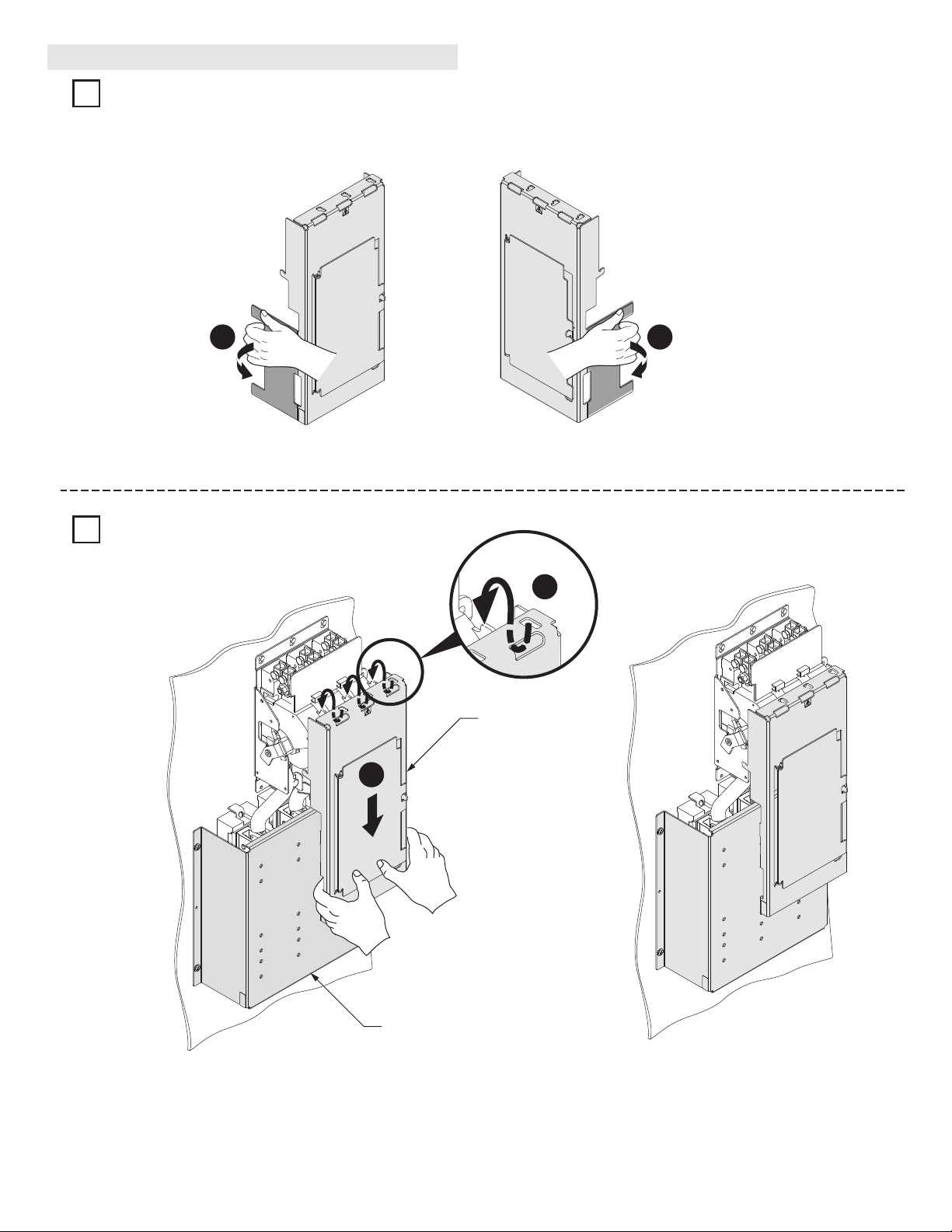
Bulletin 1494 Line Protective Switch Cover Installation
Remove break away supports on both sides of protective switch cover.
Install protective switch cover over protective fuse cover.
PN-39671
DIR 10000033845 (Version 00)
1
2
Page 3

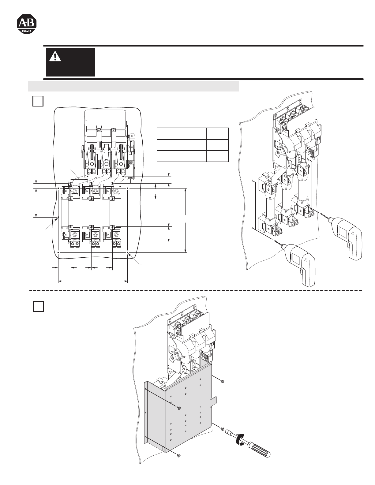
Locate and drill holes if fuse blocks are not located directly
under the disconnect switch.
Bulletin 1491 Separately Mounted Fuse Block Protective Fuse Cover Installation
PN-39671
DIR 10000033845 (Version 00)
1
14”
A
3-1/2”
7”
Optional
Mounting
Holes
3-1/2”
5/16”
4”
5”
17-1/8”
(4) - .218 Dia.
Holes for #1/4 - 20
Thread Forming Screws
5”
+.002
-
.001
A
8-1/8”
250V Class H, R
11-1/8”
600V Class H, R
600 A Fuses
Page 4

45 - 50 lb-in
Install protective fuse cover.
Bulletin 1491 Separately Mounted Fuse Block Protective Fuse Cover Installation (Continued)
PN-39671
DIR 10000033845 (Version 00)
Printed in U.S.A.
2
 Loading...