

Page 1

Installation Instructions
Bulletin 1494V Variable Depth, Flange Operated Circuit Breaker Operating Mechanisms
For use with Circuit Breakers 140G-G, 140MG-G, 140G-H, 140MG-H, 140G-I, 140MG-I, 140G-J, 140MG-J, 140G-K, 140MG-K,
140G-M, 140MG-M, 140G-N, 140MG-N
(Cat 1494V-M70; 1494V-M71; 1494V-M72)
WARNING: To prevent electrical shock, disconnect from power source before installing or servicing. Follow NFPA 70E requirements. Install in suitable enclosure. Keep free from contaminants.
Installation, adjustments, putting into service, use, assembly, disassembly, and maintenance shall be carried out by suitably trained personnel in accordance with applicable code of practice. In case of malfunction or
damage, no attempts at repair should be made. The product should be returned to the manufacturer for repair. Do not dismantle the product.
Table of Contents Page
Enclosure with Handle Cutout
1 -
Locate Circuit Breaker Mechanism 2
2 - Handle Installation 2
3 -
Cut Connecting Rod 3
4a - 140G-G, 140MG-G, 140G-I, 140MG-I Circuit Breaker Installation 3
4b - 140G-H, 140MG-H, 140G-J, 140MG-J Circuit Breaker Installation 4
4c - 140G-K, 140MG-K Circuit Breaker Installation 6
4d - 140G-M, 140MG-M Circuit Breaker Installation 7
4e - 140G-N, 140MG-N Circuit Breaker Installation 8
5 - Connecting Rod and Mechanism Adjustment Procedure 11
Enclosure without Handle Cutout
6- Locating and Installing Door Catch 12
7- Locating and Drilling Handle Holes 13
8- Circuit Breaker
Testing 14
Accessory List 15
Page 2
Variable Depth, Flange Operated Circuit Breaker Mechanisms
2
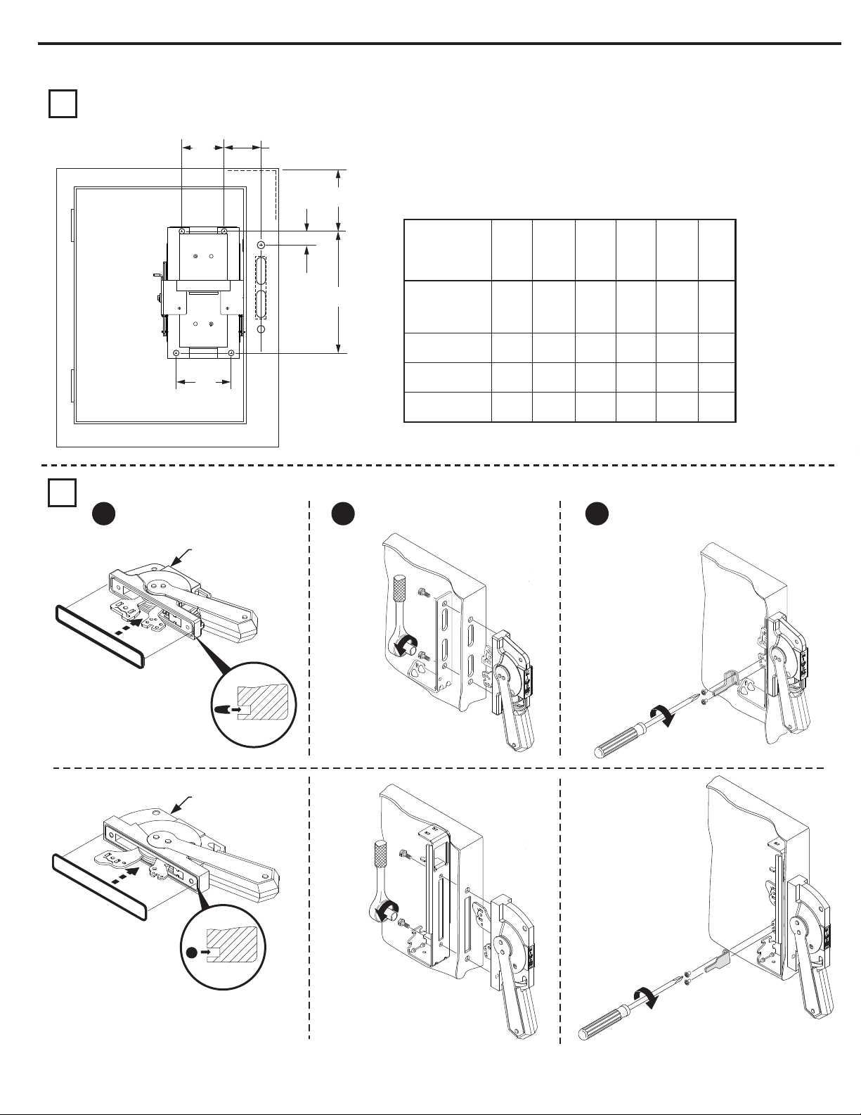
Enclosure with Handle Cutout
Locate Circuit Breaker Mechanism
1
Handle Installation
2
Install gasket.
1 2 3
CC1
CC2
BB
1494F-M1, -P1 or -S1
AA
EE
Size
DD
140G-G / 140MG-G
140G-H / 140MG-H
140G-I / 140MG-I
140G-J / 140MG-J
140G-K / 140MG-K
140G-M / 140MG-M
140G-N / 140MG-N
Install handle and spring bracket.
AA BB CC1 DDFrame
5/16" 1 - 41/64" 7 - 1/2"3"
29/64” 1 - 47/64” 9 - 5/16"4" 4 - 1/2" 12”
4 - 1/2" 4 - 1/32" 13 - 1/2"5" 12”
4 - 1/2" 4 - 1/32" 13 - 1/2"5"
CC2
3 - 1/2" 6”
5"
5" 12”
Wire
Bending
Space
Install defeater lever.
EE
1494F-M2 or -S2
IMPORTANT: Apply grease to O-Ring
to retain into handle groove.
30-40 lb-in
7-11 lb-in
60-80 lb-in
7-11 lb-in
Publication 1494V-IN105E-EN-P - September 2014 PN-242292 DIR 10000787413 (Version 04)
Page 3
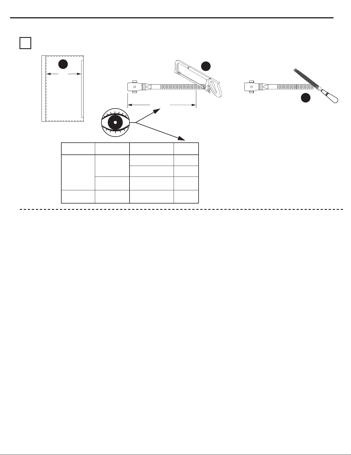
Enclosure with Handle Cutout (Cont’d)
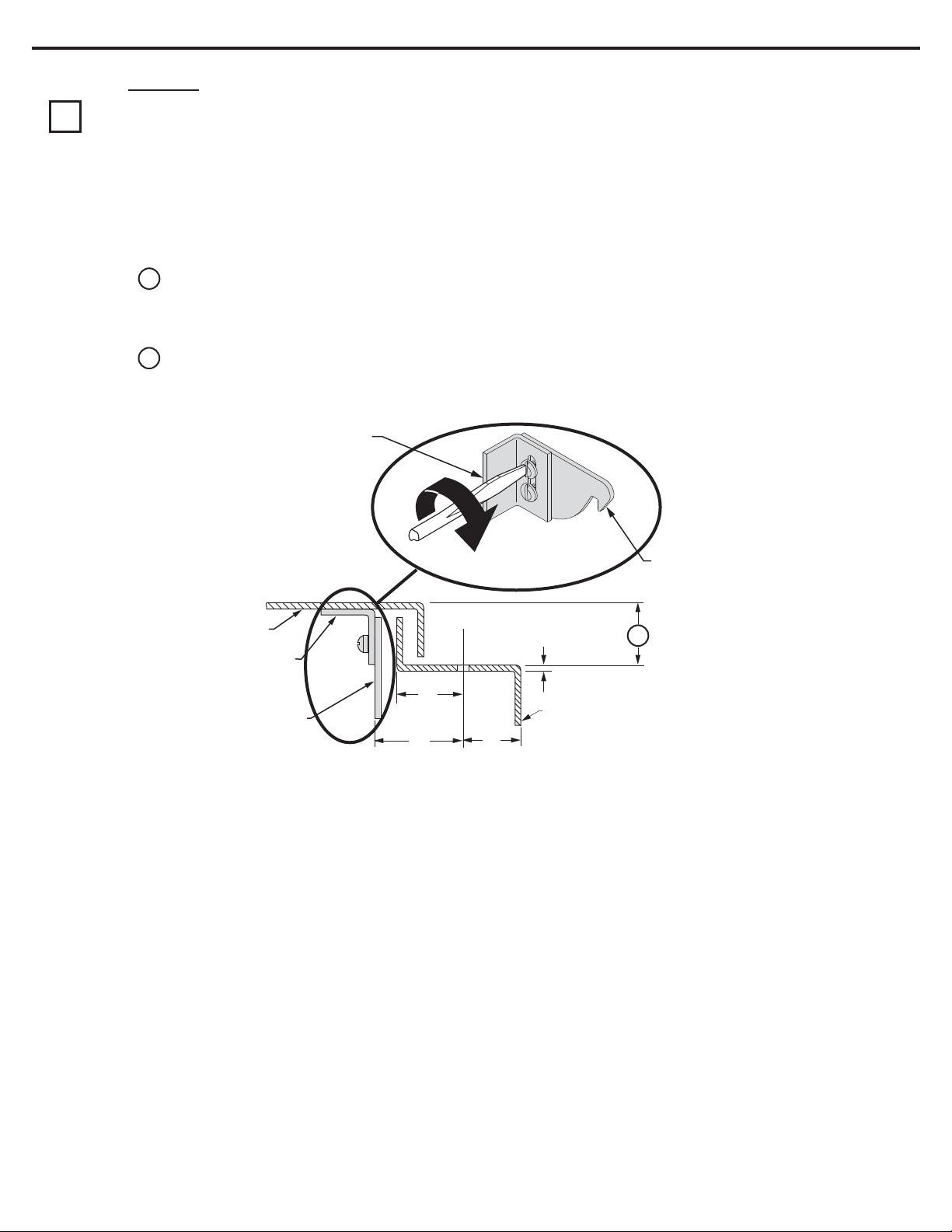
Cut Connecting Rod
3
Variable Depth, Flange Operated Circuit Breaker Mechanisms
3
1
N
Enclosure
Working Depth
(Flange to
Mounting Plate)
Connecting Rod
Catalog Number
1494V-RA4
1494V-RB4
Circuit Breaker
Mechanism
1494V-M70
1494V-M71
1494V-M72
Rod Cut
Circuit Breaker
Frame
140G-G / 140MG-G
140G-I / 140MG-I
140G-H / 140MG-H
140G-J / 140MG-J
140G-K / 140MG-K
140G-M / 140MG-M
140G-N / 140MG-N
2
3
Rod Cut
N - 3-1/2"
N - 4"
N - 4-1/2"
N - 3-3/4”
Publication 1494V-IN105E-EN-P - September 2014 PN-242292 DIR 10000787413 (Version 04)
Page 4
Variable Depth, Flange Operated Circuit Breaker Mechanisms
4
Circuit Breaker Installation
140G-G; 140MG-G; 140G-I; 140MG-I
4a
Verify that the disconnect handle and toggle on
1
the circuit breaker are in the “OFF” position.
Rotate connecting rod into drive bar
2
(10) full turns of engagement.
R
Remove liner from two-sided tape.
5
Install circuit breaker operating
3 4
mechanism into panel.
140G-I
140G-J
140G-G
140G-H
140G-G
140G-I
140G-H
140G-J
23 - 37 lb-in
Choose proper insulation barrier
as labeled. Bend side panels of
insulation barrier inward.
Align holes on insulation barrier with holes on operating mechanism.
6
Press rmly in place.
7
TAP E
L
Install circuit breaker onto insulation barrier and mechanism.
8
10 lb-in
Attach toggle adjustment plate.
9
L
23 - 37 lb-in
Go to Page 11 to assemble connecting rod and springs to handle
Publication 1494V-IN105E-EN-P - September 2014 PN-242292 DIR 10000787413 (Version 04)
Page 5
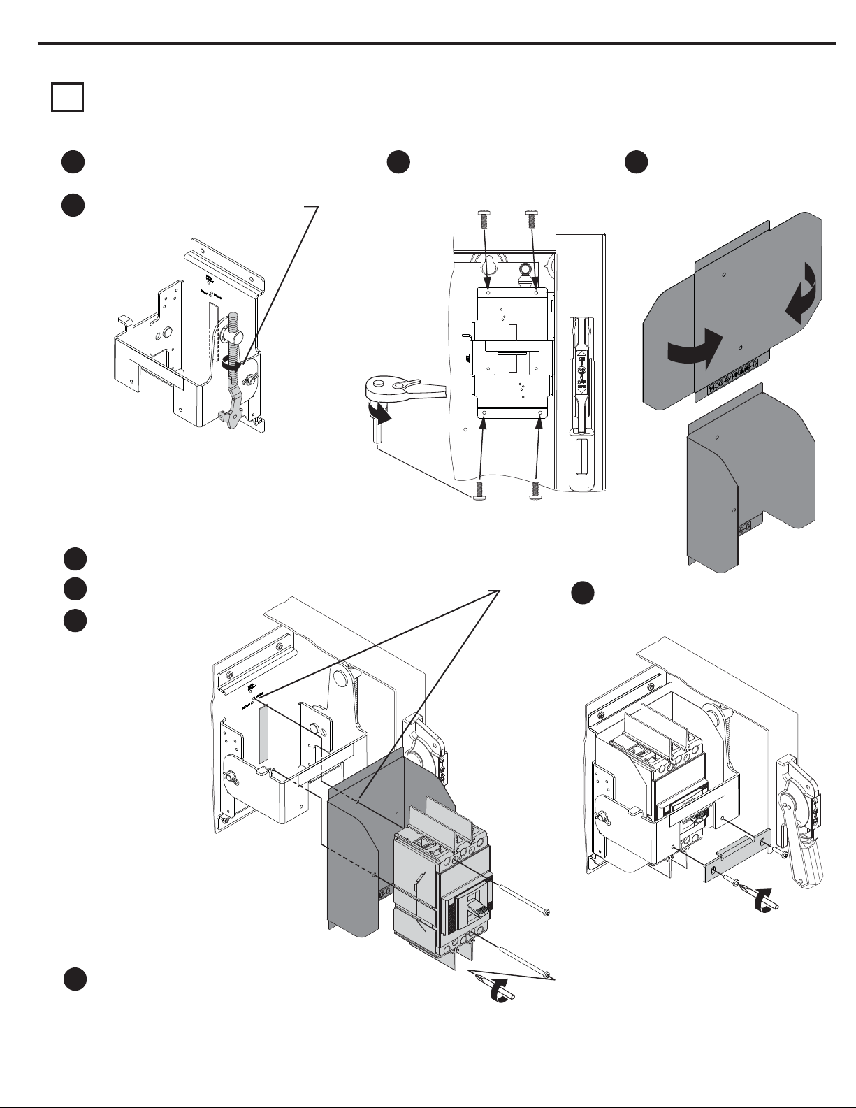
Circuit Breaker Installation (Cont'd)
140G-H; 140MG-H; 140G-J; 140MG-J
4b
Reposition bail mechanism
Variable Depth, Flange Operated Circuit Breaker Mechanisms
5
Removal
1
2
4
Verify that the disconnect handle and toggle on
9
the circuit breaker are in the “OFF” position.
Rotate connecting rod into drive bar
10
(10) full turns of engagement.
Installation
8
L
L
3
7
5
L
L
6
Install circuit breaker operating
11 12
mechanism into panel.
Choose proper insulation barrier
as labeled. Bend side panels of
insulation barrier inward.
140G-I
140G-J
140G-G
140G-H
140G-G
140G-I
R
R
23 - 37 lb-in
Publication 1494V-IN105E-EN-P - September 2014 PN-242292 DIR 10000787413 (Version 04)
140G-H
140G-J
Page 6

Variable Depth, Flange Operated Circuit Breaker Mechanisms
6
Circuit Breaker Installation (Cont'd)
140G-H; 140MG-H; 140G-J; 140MG-J
4b
Cont'd
Remove liner from two-sided tape.
13
Align holes on insulation barrier with holes on operating mechanism.
14
TAP E
L
L
Press rmly in place.
15
10 lb-in
Attach toggle adjustment plate
17
L
L
23 - 37 lb-in
Install circuit breaker onto insulation barrier and mechanism.
16
Go to Page 11 to assemble connecting rod and springs to handle
Publication 1494V-IN105E-EN-P - September 2014 PN-242292 DIR 10000787413 (Version 04)
Page 7

Circuit Breaker Installation (Cont'd)
140G-K; 140MG-K
4c
Variable Depth, Flange Operated Circuit Breaker Mechanisms
7
Verify that the disconnect handle and toggle on
1
the circuit breaker are in the “OFF” position.
Rotate connecting rod into drive bar
2
(10) full turns of engagement.
R
R
Install insulation barrier (provided with circuit breaker).
Remove liner from two-sided tape.
4
Align holes on insulation barrier with holes on operating mechanism.
5
40 - 60 lb-in
Install circuit breaker operating
3
mechanism into panel.
TAP E
L
L
Press rmly in place.
6
Install circuit breaker onto
7
insulation barrier and mechanism.
17 lb-in
Attach toggle adjustment plate
8
L
L
23 - 37 lb-in
Go to Page 11 to assemble connecting rod and springs to handle
Publication 1494V-IN105E-EN-P - September 2014 PN-242292 DIR 10000787413 (Version 04)
Page 8

Variable Depth, Flange Operated Circuit Breaker Mechanisms
8
Circuit Breaker Installation (Cont'd)
140G-M; 140MG-M
4d
Verify that the disconnect handle and toggle on
1
the circuit breaker are in the “OFF” position.
Rotate connecting rod into drive bar
2
(10) full turns of engagement.
Install insulation barrier (provided with circuit breaker).
Remove liner from two-sided tape.
4
90 - 130 lb-in
Install circuit breaker operating
3
mechanism into panel.
Align holes on insulation barrier with holes on operating mechanism.
5
TAP E
Press rmly in place.
6
17 lb-in
Attach toggle adjustment plate
8
40 - 60 lb-in
Install circuit breaker onto
7
insulation barrier and
mechanism.
Go to Page 11 to assemble connecting rod and springs to handle
Publication 1494V-IN105E-EN-P - September 2014 PN-242292 DIR 10000787413 (Version 04)
Page 9

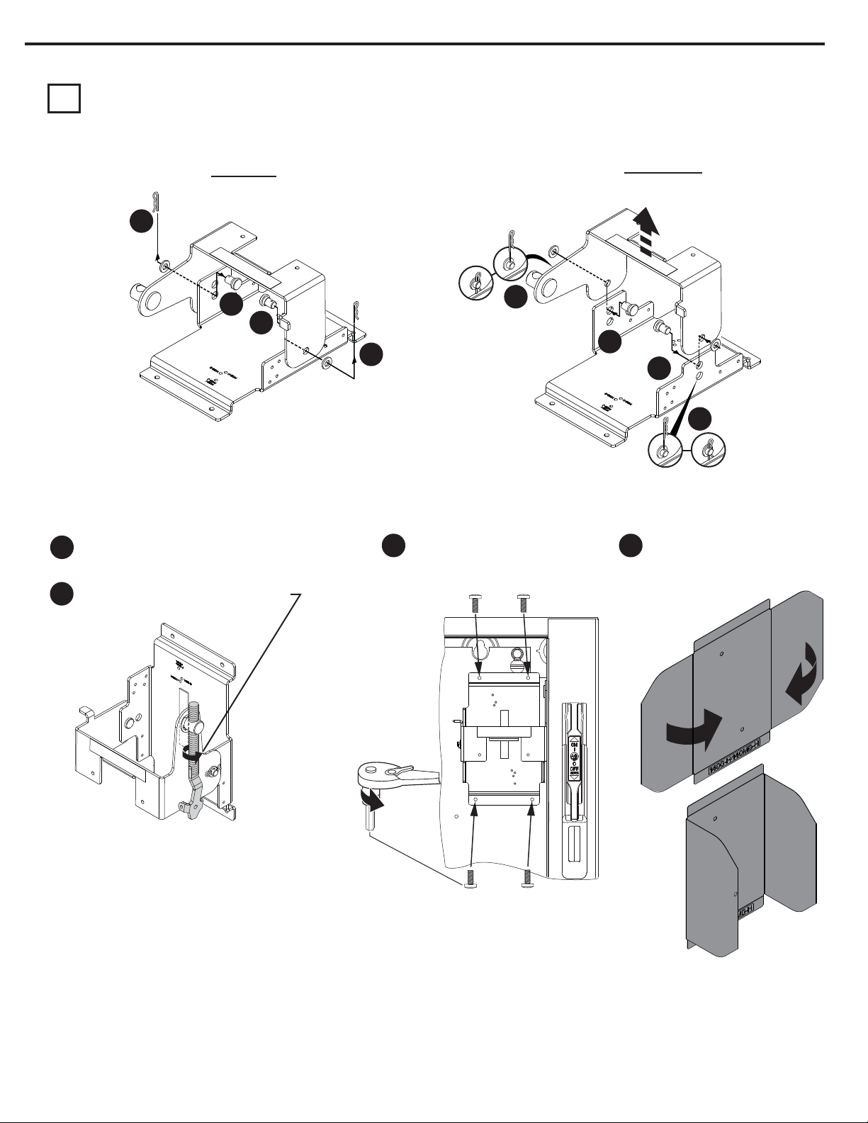
Circuit Breaker Installation (Cont'd)
140G-N; 140MG-N
4e
Reposition bail mechanism
1
Variable Depth, Flange Operated Circuit Breaker Mechanisms
4
40 - 60 lb-in
40 - 60 lb-in
23 - 37 lb-in
2
9
5
6
Verify that the disconnect handle
7
and toggle on the circuit breaker
are in the “OFF” position.
3
Rotate connecting rod into drive
8
bar (10) full turns of engagement
Publication 1494V-IN105E-EN-P - September 2014 PN-242292 DIR 10000787413 (Version 04)
Page 10

Variable Depth, Flange Operated Circuit Breaker Mechanisms
10
Circuit Breaker Installation (Cont'd)
140G-N; 140MG-N
4e
Cont'd
9
Install circuit breaker operating
mechanism into panel.
Install insulation barrier (provided with lugs).
10
11
90 - 130 lb-in
Remove liner from two-sided tape.
Align holes on insulation barrier with holes on operating mechanism.
TAP E
L
Attach toggle adjustment plate.
14
Press rmly in place.
12
Install circuit breaker
13
onto insulation barrier
and mechanism.
22 lb-in
40 - 60 lb-in
Go to Page 11 to assemble connecting rod and springs to handle
Publication 1494V-IN105E-EN-P - September 2014 PN-242292 DIR 10000787413 (Version 04)
Page 11

Connecting Rod and Spring Assembly to Handle
5
2
1
L
L
Variable Depth, Flange Operated Circuit Breaker Mechanisms
Hitch Pin
Connecting
Rod
2
1
Primary Link
11
3
L
L
4
Publication 1494V-IN105E-EN-P - September 2014 PN-242292 DIR 10000787413 (Version 04)
Page 12
Variable Depth, Flange Operated Circuit Breaker Mechanisms
12
Enclosure without Handle Cutout
Locating and Installing Door Catch
6
Provided with projections for welding.
·
Projections can also be used as a guide for drilling holes.
·
Can be used as a template to drill corresponding holes in the enclosure door.
·
User to supply the hardware for fastening the bracket.
·
Fasteners must provide the degree of ingress protection for the environmental rating of the enclosure.
·
The bracket hardware must be inaccessible to unauthorized personnel.
·
Dimension K (3/4" to 1")
·
When using large disconnect handle kit only (1494F-M2 or -S2), use door catch provided with handle kit.
·
When using large disconnect handle kit and small door hardware kits (1494V-L1, -LL1, -L2 or -LL2), use door catch provided with door
·
hardware kit.
Dimension K (1-1/8" to 1-3/8")
·
When using large disconnect handle kit only (1494F-M2 or -S2), use door catch (40492-080-02) which can be ordered from factory.
·
When using large disconnect handle kit and large door hardware kits (1494V-L3 or -LL3), use door catch provided with door hardware kit.
·
Enclosure Door
Door Catch
Mounting Bracket
Door Catch
Door Catch
Mounting Bracket
TOP VIEW
Top
22 - 37 lb-in
Door Catch
Flange
Thickness
C
Enclosure
D
B
Base
K
Publication 1494V-IN105E-EN-P - September 2014 PN-242292 DIR 10000787413 (Version 04)
Page 13

Variable Depth, Flange Operated Circuit Breaker Mechanisms
FRAME HANDL E
140G-G, H
140MG-G, H
1494F-M1
(Figure 1)
3-1/2” 29/32” 1-3/32” 1-5/8” 2-11/32” 4-11/16” 1-9/16” 1” 7/8”
140G-I, J
140MG-I, J
1494F-M1
(Figure 1)
1494F-M1
(Figure 1)
1494F-M2
(Figure 2)
1494F-M2
(Figure 2)
10-29-32” 29/32” 1-3/32” 1-5/8” 2-11/32” 4-11/16” 1-9/16” 1” 7/8”
140G-K
140MG-K
13-3/32” 29/32” 1-3/32” 1-5/8” 2-11/32” 4-11/16” 1-9/16” 1” 7/8”
140G-M
140MG-M
17-5/16” 1-3/8” 1-3/32” 2” 3-23/32” 6-1/2” 5/16” 5-1/2” NA
140G-N
140MG-N
21-7/8” 1-3/8” 1-3/32” 2” 3-23/32” 6-1/2” 5/16” 5-1/2” NA
Enclosure without Handle Cutout
Enclosures with a Flange Thickness less than 3/16" use dimensions below to install disconnect handle.
·
Enclosures with a Flange Thickness 3/16" and greater use dimensions in Alternate Mounting Kit 1494V-H6 to install disconnect handle.
·
Locating and Drilling Handle Holes
7
13
C
B
A
E
(2) .265 Dia.
Holes
H
Door Catch
Mounting
Bracket
Figure 1 Figure 2
D
To make slot
drill (3) 1/2"
diameter holes
and remove burrs
A
(MIN)
B
(MIN)
G
C
(MAX)
F
DE F GHJ
J
H
Door Catch
Mounting
Bracket
C
B
A
E
Square corners
or up to
1/4" radius
D
1/2"
1/4"
(2) .328 Dia.
Holes
G
F
H
Publication 1494V-IN105E-EN-P - September 2014 PN-242292 DIR 10000787413 (Version 04)
Page 14

Variable Depth, Flange Operated Circuit Breaker Mechanisms
14
Testing of Circuit Breaker
8
L
L
Connecting Rod
Hitch Pin
Spring
Handle Link
Defeator
Lever
140G / MG-G, H, I, J
140G / MG-K
140G / MG-M
140G / MG-N
23 - 37 lb-in
40 - 60 lb-in
“ON” Position
Toggle Adjustment Plate
1. Move defeater lever down and move handle to the ON position.
2. If the circuit breaker does not turn “ON”, loosen (2) screws on toggle adjustment plate.
3. Move toggle adjustment plate toward line terminals.
4. Tighten the (2) toggle adjustment plate screws to torque value in table above.
5. If the circuit breaker still can not be turned “ON”, return handle to the OFF position.
6. Unhook spring, remove hitch pin and separate connecting rod from handle link.
7. Turn connecting rod one full turn clockwise.
8. Reattach connecting rod and handle link, hitch pin and spring.
9. If the circuit breaker still can not be turned “ON”, repeat Steps 6, 7 and 8 if necessary.
“OFF” Position
1. Move handle to the “OFF” position.
2. If the cirucit breaker does not turn “OFF”, unhook spring, remove hitch pin and separate connecting rod from handle link.
3. Turn connecting rod one full turn clockwise.
4. Reattach connecting rod and handle link, hitch pin and spring and then retest.
5. If the circuit breaker still can not be turned “OFF”, repeat steps 2, 3 & 4.
“RESET” Position
1. Manually trip the circuit breaker while in the “ON” position.
2. Move handle to the “OFF” position to reset.
3. If circuit breaker does not reset, unhook spring, remove hitch pin and separate connecting rod from handle link.
4. Adjust connecting rod by turning it clockwise 1-2 turns and then retest.
5. Repeat steps 1-4 until circuit breaker resets.
6. Verify that the circuit breaker can be turned “ON”, “OFF” and “RESET” following the steps above.
NOTE: Twisting of the bail mechanism is acceptable when the handle is in the full “ON” or full “OFF” position.
Publication 1494V-IN105E-EN-P - September 2014 PN-242292 DIR 10000787413 (Version 04)
Page 15

Variable Depth, Flange Operated Circuit Breaker Mechanisms
Components Cat No. Description Circuit Breaker
140G-G, 140MG-G
1494F-M1
1494F-P1
1494F-S1
5-1/2" Painted Metal Handle
5-1/2" Molded Handle
5-1/2" Stainless Steel Handle
140G-H, 140MG-G
140G-I, 140MG-I
140G-J, 140MG-J
140G-K, 140MG-K
15
1494F-M2
1494F-S2
1494V-RA4
1494V-RB4
1494V-M70
1494V-M71 Circuit breaker mechanism
1494V-M72
7-1/2" Painted Metal Handle
7-1/2" Stainless Steel Handle
Connecting Rod
Enclosure Working Depth: 6-3/4" to 23"
Standard Connecting Rod
Enclosure Working Depth: 6-3/4" to 23"
Circuit breaker mechanism
Circuit breaker mechanism
140G-M, 140MG-M
140G-N, 140MG-N
140G-G, 140MG-G
140G-H, 140MG-G
140G-I, 140MG-I
140G-J, 140MG-J
140G-K, 140MG-K
140G-M, 140MG-M
140G-N, 140MG-N
140G-G, 140MG-G
140G-H, 140MG-G
140G-I, 140MG-I
140G-J, 140MG-J
140G-K, 140MG-K
140G-M, 140MG-M
140G-N, 140MG-N
1495-N85
1495-N86
1495-N87
(1) N.O. Auxiliary Contact
(1) N.C. Auxiliary Contact
Insulation Kit
140G-G, 140MG-G
140G-H, 140MG-G
140G-I, 140MG-I
140G-J, 140MG-J
140G-K, 140MG-K
140G-M, 140MG-M
140G-N, 140MG-N
140G-G, 140MG-G
140G-H, 140MG-G
140G-I, 140MG-I
140G-J, 140MG-J
Publication 1494V-IN105E-EN-P - September 2014 PN-242292 DIR 10000787413 (Version 04)
Page 16

1
Bulletins: 507, 513, 513H, 523E, 523F, 523G, 1233, 1233X, 1233V
NEMA
Starter
Size
Horsepower Rating
For Combination Starter
Voltage
1/10..1/3 HP 200V - 230V
1/10…1 HP 460V
1/10…1 HP 575V
1/2…1 HP 200V - 230V
0
1-1/2…3 HP 460V
1-1/2…3 HP 575V
1-1/2…3 HP 200V - 230V
5 HP 460V
5 HP 575V
1/10…1/3 HP 200V - 230V
1/10…1 HP 460V
1/10…1 HP 575V
1/2…1 HP 200V - 230V
1-1/2…3 HP 460V
1-1/2…3 HP 575V
1-1/2…3 HP 200V - 230V
5 HP @ 200V 200V 30A 140MG-G8P-C30
5…7-1/2 HP 460V
5…7-1/2 HP 575V
5…7-1/2 HP 230V 30A 140MG-G8P-C30
5…7-1/2 HP 200V 50A 140MG-G8P-C50
10 HP 460V
10 HP 575V
10 HP 200V - 230V 50A 140MG-G8P-C50
15 HP 460V
2
15 HP 575V
15 HP 230V 100A 140MG-G8P-D10
20…25 HP 460V
20…25 HP 575V
15…25 HP 200V - 230V 100A
30 HP 575V 50A 140MG-G8P-C50
3
30 HP 230V 150A 140MG-J8P-D15
30…50 HP 460V
40…50 HP 575V
30 HP 200V 150A 140MG-J8P-D15
40…50 HP 200V - 230V 200A 140MG-J8P-D20
4
60 HP 575V 100A 140MG-G8P-D10
60…75 HP 150A 140MG-J8P-D15
100 HP 200A 140MG-J8P-D20
460V
75…100 HP 575V 150A 140MG-J8P-D15
50 HP 250A 140MG-J8P-D25
60 HP 300A 140MG-K8P-D30
200V
75 HP 400A 140MG-K8P-D40
5
100 HP 400A 140MG-K8P-D40
60…75 HP 300A 140MG-K8P-D30
230V
125 HP 575V 200A 140MG-J8P-D20
125…150 HP 300A 140MG-K8P-D30
200 HP 400A 140MG-K8P-D40
460V
150…200 HP 575V 300A 140MG-K8P-D30
Note: Conta ct Rockwell Automation for c ircuit breaker use in bulletin 503 and 503L.
Circuit
Breaker
Rating
15A
30A
30A
50A
100A
Circuit Breaker
Cat No.
140MG-G8P- C1515A
140MG-G8P-C15
140MG-G8P-C30
140MG-G8P-C30
140MG-G8P-C50
140MG-G8P-D10
140MG-G8P-D10
Rockwell Automation maintains current product environmental information on its website at http://www.rockwellautomation.com/rockwellautomation/about-us/sustainability-ethics/product-environmental-compliance.page.
Allen-Bradley, Rockwell Software, and Rockwell Automation are trademarks of Rockwell Automation, Inc.
Trademarks not belonging to Rockwell Automation are property of their respective companies.
Publication 1494V-IN105E-EN-P - September 2014
Copyright © 2014 Rockwell Automation, Inc. All Rights Reserved. Printed in USA.
DIR 10000787413 (Version 04)
PN-242292
 Loading...