

Page 1
Installation Instructions
Solar Combiner Enclosure
Catalog Numbers
Description
1000-SB006, 1000-SB012
Top ic Pag e
Description 1
Important Safety Instructions 3
Nameplate Data 4
Planning for Installation 4
Install the Solar Combiner Enclosure 5
Wire the Solar Combiner Enclosure 8
Dimensions 10
Specifications 12
Additional Resources 12
The solar combiner enclosure combines inputs from multiple solar arrays into an
output circuit. Two catalog numbers are available.
Table 1 - Product Selection
Cat. No. Number of Poles Voltage Rating
1000-SB006 6
1000-SB012 12
600V DC (continuous duty)
Solar combiner enclosures support these features:
• Listed to UL 1741 – Inverters, Converters, Controllers, and
Interconnecting System Equipment for Use with Distributed Energy
Sources
• Line and load terminals marked for using 90 °C (194 °F) copper wire
• UL Type 3, 4/4X, 12, and 13 enclosure ratings
• Fuse holders and power distribution blocks
• Configured for positive and negative grounded arrays
Page 2
2 Solar Combiner Enclosure
IMPORTANT
Important User Information
Solid-state equipment has operational characteristics differing from those of electromechanical equipment. Safety
Guidelines for the Application, Installation and Maintenance of Solid State Controls (publication SG I - 1 . 1
your local Rockwell Automation® sales office or online at http://www.rockwellautomation.com/literature
important differences between solid-state equipment and hard-wired electromechanical devices. Because of this difference,
and also because of the wide variety of uses for solid-state equipment, all persons responsible for applying this equipment
must satisfy themselves that each intended application of this equipment is acceptable.
In no event will Rockwell Automation, Inc. be responsible or liable for indirect or consequential damages resulting from the
use or application of this equipment.
The examples and diagrams in this manual are included solely for illustrative purposes. Because of the many variables and
requirements associated with any particular installation, Rockwell Automation, Inc. cannot assume responsibility or
liability for actual use based on the examples and diagrams.
No patent liability is assumed by Rockwell Automation, Inc. with respect to use of information, circuits, equipment, or
software described in this manual.
Reproduction of the contents of this manual, in whole or in part, without written permission of Rockwell Automation,
Inc., is prohibited.
Throughout this manual, when necessary, we use notes to make you aware of safety considerations.
available from
) describes some
WARNING: Identifies information about practices or circumstances that can cause an explosion in a hazardous environment, which may
lead to personal injury or death, property damage, or economic loss.
ATTENTION: Identifies information about practices or circumstances that can lead to personal injury or death, property damage, or
economic loss. Attentions help you identify a hazard, avoid a hazard, and recognize the consequence
SHOCK HAZARD: Labels may be on or inside the equipment, for example, a drive or motor, to alert people that dangerous voltage may be
present.
BURN HAZARD: Labels may be on or inside the equipment, for example, a drive or motor, to alert people that surfaces may reach
dangerous temperatures.
Identifies information that is critical for successful application and understanding of the product.
These symbols are used in this publication.
Ground symbol
Direct current symbol
Rockwell Automation Publication 1000-IN002B-EN-P - April 2012
Page 3
Solar Combiner Enclosure 3
IMPORTANT
IMPORTANT SAFETY INSTRUCTIONS
SAVE THESE INSTRUCTIONS.
This publication contains important instructions for 6- and 12-pole solar
combiner enclosures, catalog numbers 1000-SB006 and 1000-SB012, that must
be followed during installation and maintenance:
• Use 90 °C (194 °F) copper wire only.
• This product is intended for operation in an environment with a
maximum temperature rating of 40 °C (104 °F)
• For entry into the enclosure, use only UL-Listed raintight or wet location
hubs (for UL Type 3R, 12, and 13) that comply with the requirements in
the Standard for Conduit, Tubing, and Cable fittings (UL514B).
• Use only UL-Listed watertight hubs (for UL Type 4/4X) that comply
with the requirements in the Standard for Conduit, Tubing, and Cable
fittings (UL514B).
Bonding between conduit connections is not automatic and must be provided as part
of the installation.
SHOCK HAZARD: Disconnect and lock out power before entering or performing
maintenance on the enclosure.
SHOCK HAZARD: Normally-grounded conductors may be ungrounded and energized
when a ground fault is indicated.
SHOCK HAZARD: When the photovoltaic array is exposed to light, it supplies a DC
voltage to this equipment.
Follow National Electric Code, ANSI/NFPA 70, Requirements
The system installer is responsible for the following:
• Follow National Electric Code wiring methods
• Follow cUL certification requirements, including
CSA C22.2 No. 107.1-01, clause 154.5.2
• For Canadian installations, following the wiring methods per the
Canadian Electrical Code, Part II
• System grounding, if required by Section 250 of the National Electric
Code (DC input and output circuits are isolated from the enclosure)
• Install photovoltaic system grounding per the requirements of
Sections 690.41…690.47 of the National Electric Code
Rockwell Automation Publication 1000-IN002B-EN-P - April 2012
Page 4
4 Solar Combiner Enclosure
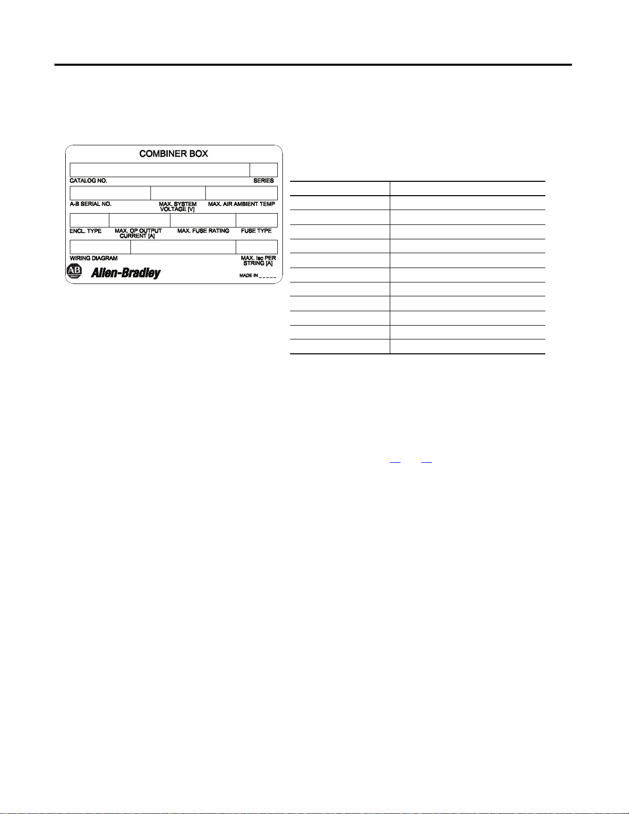
The following product information is provided on the nameplate.
Table 2 - Nameplate Fields
Field Description
CATALOG NO. Catalog number
SERIES Series letter of the product
A-B SERIAL NO. Product serial number
MAX. SYSTEM VOLTAGE [V] Voltage of the system in volts, max
MAX. AIR AMBIENT TEMP. Air ambient temperature in degrees Celsius, max
ENCL. TYPE UL enclosure type
RATED INPUT Operating output current, max
MAX. FUSE RATING Fuse rating, max
FUSE TYPE Fuse type
WIRING DIAGRAM Schematic number
MAX. Isc PER STRING [A] Short circuit current per string, max
Nameplate Data
Figure 1 - Nameplate Sample
Each solar combiner enclosure has a nameplate on the enclosure or enclosure
door, similar to the example shown below.
Planning for Installation
When planning the location for your solar combiner enclosure, consider the
following:
• Conduits
• Type of installation
• Product dimensions (see pages 10
and 11)
• Mounting requirements
• Connection to other equipment
• Enclosure rating
• Environmental conditions
• Future needs
Environment and Enclosure
Most applications require installation in an industrial enclosure to reduce the
effects of electrical interference and environmental exposure. Locate your
controller as far a possible from power lines, load lines, and other sources of
electrical noise, such as hard-contact switches, relays, and AC motor drives.
Rockwell Automation Publication 1000-IN002B-EN-P - April 2012
Page 5

Solar Combiner Enclosure 5
Environmental Ratings
The enclosure is rated for IP 66 and UL Type 3, 4, 4X, 12, and 13 applications
when used with the proper UL Type hub or conduit fittings. The enclosures are
constructed for either indoor or outdoor use, and provide a degree of protection
to personnel against incidental contact with the enclosed environment. They
provide a degree of protection against snow, windblown dust, splashing water,
and hose-directed water. They will be undamaged by the external formation of ice
on the enclosure and provide corrosion protection.
The unit is rated to function with a temperature range of -20 °C…40 °C
(-4 °F…104 °F).
Install the Solar Combiner Enclosure
Follow these requirements during installation:
• Bonding between the grounding bushings and the equipment grounding
terminals must be provided in accordance with applicable codes.
• A 1/2-in. minimum electrical clearance must be maintained between the
grounding adapter wire terminal and electrically live components.
Prepare the Enclosure
Follow these steps to prepare the enclosure.
1. From the table below, select the appropriate combination of conduit
connector and grounding adapter based on your type of installation, and
determine the required hole size in the bottom or side of the enclosure.
4/4X Conduit Connector (Hub) Grounding Adapter
Conduit Size
19.1 mm (3/4 in.) 28.6mm (1-1/8 in.) 1490-N9 1490-N20 12-8 14-8
25.4 mm (1 in.) 34.9 mm (1-3/8 in.) 1490-N10 1490-N21 12-8 14-8
31.8 mm (1-1/4 in.) 44.5 mm (1-3/4 in.) 1490-N11 1490-N22 12-4 14-4
38.1 mm (1-1/2 in.) 50.8 mm (2 in.) 1490-N5 1490-N23 8-1/0 8-1/0
50.8 mm (2 in.) 63.5 mm (2-1/2 in.) 1490-N6 1490-N24 8-1/0 8-1/0
Hole Size Cat. No. Cat. No.
Ground Wire Range (AWG)
1000-SB006 1000-SB012
Holes must be at least 6 in. (15.24 cm) below the output terminal in the
enclosure side of the 12-pole assembly. When using 4 AWG wire in the
6-pole assembly, the hole must be at least 2 in. (5.08 cm) below the output
terminal in the enclosure side.
For more details, reference table 7.2 of UL 1741.
Rockwell Automation Publication 1000-IN002B-EN-P - April 2012
Page 6

6 Solar Combiner Enclosure
TIP
IMPORTANT
IMPORTANT
TIP
Condu it
Condu it
Connector (hub)
O-ring
(outside enclosure)
Enclosure
Hole Size
Locknu t
Posit ioning Tab
Wiring Terminal
Grounding Adapter
Locknu t
2. Use a hole cutter or hole saw to create holes at the top and bottom of the
enclosure.
When using a hole cutter, place the punch on the inside of the enclosure and
draw it through to the outside.
Install the Conduit Connector and Grounding Adapter
Install the conduit connector (hub) and grounding adapter by following these
steps.
To guard against enclosure damage, align the conduit to prevent unnecessary stress on
the enclosure walls.
For conduit hubs, use only raintight or wet-location hubs that comply with the
requirements in the UL514B standard for Fittings for Conduit and Outlet Boxes.
1. Place the conduit connector (hub) and O-ring onto the conduit in the
desired locations.
2. Secure the conduit connector to the enclosure by using the locknut.
3. Install the grounding adapter as shown in Figure 2
and secure with the
locknut.
Make sure that the wiring terminal is positioned so that it will be accessible
after installation.
Figure 2 - Connector and Adapter Installation
Rockwell Automation Publication 1000-IN002B-EN-P - April 2012
Page 7

Solar Combiner Enclosure 7
10.0 mm
(.40 in.)
7.0 mm
(.28 in.)
57.0 mm
(2.25 in.)
16.0 mm
(.63 in.)
25.2 mm
(.98 in.)
Ø24 mm
(.94 in.)
Ø6.83 mm
(.27 in.)
Ø15.95 mm
(.63 in.)
4.0 mm
(.16 in.)
5.7 mm
(.22 in.)
3.0 mm
(.12 in.)
X
Y
Threaded brass insert
M5 x 0.8 mm
(4) places
Mounting Bracket
Base (Bottom View)
Enclosure X Y
1000-SB006
1000-SB012
238 mm (9.38 in.) 238 mm (9.38 in.)
340 mm (13.38 in.) 241 mm (9.50 in.)
Install an External Mounting Bracket (optional)
You can install an optional mounting bracket, catalog number 598-N13, for the
enclosure.
Use four #8 hardware with mounting brackets or four #10 hardware without
mounting brackets.
Figure 3 - Mounting Bracket Dimensions
Rockwell Automation Publication 1000-IN002B-EN-P - April 2012
Page 8

8 Solar Combiner Enclosure
Wire the Solar Combiner Enclosure
Refer to the wiring diagrams below when installing the enclosure.
Figure 4 - Wiring the 6-pole Solar Combiner Enclosure
Rockwell Automation Publication 1000-IN002B-EN-P - April 2012
Page 9

Figure 5 - Wiring the 12-pole Solar Combiner Enclosure
Solar Combiner Enclosure 9
Rockwell Automation Publication 1000-IN002B-EN-P - April 2012
Page 10

10 Solar Combiner Enclosure
280 mm REF.
(11.02 in.)
280 mm REF.
(11.02 in.)
95.3 mm
(3.75 in.)
13.9 mm
(0.55 in.)
14.2 mm
(0.56 in.)
165 mm
(6.48 in.)
69.3 mm
(2.73 in.)
214 mm
(8.42 in.)
CUSTOMER SIDE
105 mm
(4.13 in.)
42.9 mm
(1.69 in.)
38.1 mm
(1.50 in.)
Dimensions are in inches (mm).
Dimensions
Figure 6 - 6-pole Solar Combiner Enclosure (Catalog Number 1000-SB006)
Rockwell Automation Publication 1000-IN002B-EN-P - April 2012
Page 11

95.3 mm
(3.75 in.)
14.2 mm
(0.56 in.)
57.9 mm
(2.28 in.)
37.3 mm
(1.47 in.)
63.8 mm
(2.51 in.)
77.2 mm
(3.08 in.)
95.3 mm
(3.75 in.)
380 mm
(14.96 in.)
351 mm
(13.82 in.)
100 mm
(3.94 in.)
100 mm
(3.94 in.)
50.3 mm
(1.98 in.)
13.9 mm
(0.55 in.)
251 mm
(9.88 in.)
280 mm
(11.02 in.)
180 mm
(7.09 in.)
59.7 mm
(2.35 in.)
57.7 mm
(2.27 in.)
30.0 mm
(1.18 in.)
Dimensions are in inches (mm).
Solar Combiner Enclosure 11
Figure 7 - 12-pole Solar Combiner Enclosure (Catalog Number 1000-SB012)
Rockwell Automation Publication 1000-IN002B-EN-P - April 2012
Page 12

Specifications
Attribute 1000-SB006 1000-SB012
Number of input circuits, max 6 12
Number of poles 6 12
Voltage rating (continuous duty) 600V DC 600V DC
Operating current (DC), max 72 144
Rated input current (DC) 12 A
Fuse rating (Class CC), max 15 A 12 A
Ambient air temperature, max 40 °C (104 °F) 40 °C (104 °F)
(1) Consult the factory for higher currents up to 15 A.
(1)
12 A
(1)
Additional Resources
These documents contain additional information concerning related products
from Rockwell Automation.
Resource Description
Industrial Automation Wiring and Grounding Guidelines,
publication 1770-4.1
Product Certifications website, http://www.ab.com Provides declarations of conformity, certificates, and other
Provides general guidelines for installing a Rockwell
Automation industrial system.
certification details.
You can view or download publications at
http://www.rockwellautomation.com/literature/
. To order paper copies of
technical documentation, contact your local Allen-Bradley® distributor or
Rockwell Automation sales representative.
Allen-Bradley, Rockwell Software, Rockwell Automation, and TechConnect are trademarks of Rockwell Automation, Inc.
Trademarks not belonging to Rockwell Automation are property of their respective companies.
Publication 1000-IN002B-EN-P - April 2012 PN-126891
Supersedes Publication 1000-IN002A-EN-P - July 2011 Copyright © 2012 Rockwell Automation, Inc . All rights reserved. Printed in the U.S.A.
 Loading...