

Page 1
Safety Lockout
System
Bulletin 1000
User Manual
Page 2
Important User Information
Because of the variety of uses for the products described in this publication,
those responsible for the application and use of this control equipment must
satisfy themselves that all necessary steps have been taken to assure that each
application and use meets all performance and safety requirements, including
any applicable laws, regulations, codes and standards.
The illustrations, charts, sample programs and layout examples shown in this
guide are intended solely for purposes of example. Since there are many
variables and requirements associated with any particular installation,
Allen-Bradley does not assume responsibility or liability (to include intellectual
property liability) for actual use based upon the examples shown in this
publication.
Allen-Bradley publication SGI-1.1, Safety Guidelines for the Application, Installation
and Maintenance of Solid-State Control (available from your local Allen-Bradley
office), describes some important differences between solid-state equipment
and electromechanical devices that should be taken into consideration when
applying prod uct s such as tho se de sc ribe d in this pu blica tio n.
Reproduction of the contents of this copyrighted publication, in whole or part,
without written permission of Rockwell Automation, is prohibited.
Throughout this manual we use notes to make you aware of safety
considerations:
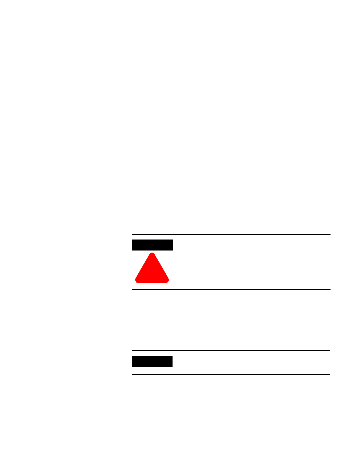
ATTENTION
Identifies infor matio n about practices or circumsta nces
that can lead to pers onal in jury or death, prop er ty d am age
or economic loss.
!
Attention st ate ment s hel p you to :
• identif y a hazard
• avoid a haza r d
• recognize the consequences
IMPORTANT
Allen-Bradley is a trademark of Rockwell Automation
Identifies informa tion that is critical for successful
application an d und ers ta ndin g of the pro du ct.
Page 3

European Communities (EC) Directive Compliance
If this product has the CE mark it is approved for installation within the
European Union and EEA regions. It has been designed and tested to meet
the following directives.
EMC Directive
This product is tested to meet the Council Directive 89/336/EC
Electromagnetic Compatibility (EMC) by applying the following standards, in
whole or in part, documented in a technical construction file:
• EN 5008 1-2 EMC — Gen eric Emission S tandar d, Pa rt 2 — Indus trial
Environment
• EN 50082-2 EMC — Generic Immunity Standard, Part 2 — Industrial
Environment
This product is intended for use in an industrial environment.
Low Voltage Directive
This product is tested to meet Council Directive 73/23/EEC Low Voltage,
by applying the safety requirements of EN 61131-2 Programmable
Controllers, Part 2 — Equipment Requirements and Tests. For specific
information required by EN 61131-2, see the appropriate sections in this
publication, as well as the Allen-Bradley publication Industrial Automation
Wiring and Grounding Guidelines For Noise Immunity, publication 1770-4.1.
This equipment is classified as open equipment and must be mounted in an
enclosure duri ng op era tion to provide safety protec tio n.
Page 4

Notes:
Page 5

Table of Contents
Preface
Purpose of the Safety Lockout System . . . . . . . . . . . . . . . . . . . Preface-1
Safety Requirements and Guidelines. . . . . . . . . . . . . . . . . . . . . Preface-1
Definitions . . . . . . . . . . . . . . . . . . . . . . . . . . . . . . . . . . . . . . . . . Preface-1
Description of Use. . . . . . . . . . . . . . . . . . . . . . . . . . . . . . . . . . . Preface-2
Simplified Wiring Diagram and
Sequence of Operation . . . . . . . . . . . . . . . . . . . . . . . . . . . . . . . Preface-2
Application . . . . . . . . . . . . . . . . . . . . . . . . . . . . . . . . . . . . . . . . . Preface-4
Specifications . . . . . . . . . . . . . . . . . . . . . . . . . . . . . . . . . . . . . . . Preface-4
Chapter 1 Installation Instructions
Chapter 2 Commissioning Box and Switch
Chapter 3 Operational Procedure
Component Function and Description. . . . . . . . . . . . . . . . . . . . . . . . 3-1
Servicing . . . . . . . . . . . . . . . . . . . . . . . . . . . . . . . . . . . . . . . . . . . . . . . . 3-3
Chapter 4 SLS Sequence of Operation
Chapter 5 Troubleshooting Guide
Troubleshooting Guide . . . . . . . . . . . . . . . . . . . . . . . . . . . . . . . . . . . . 5-1
SLS Test Procedure . . . . . . . . . . . . . . . . . . . . . . . . . . . . . . . . . . . . . . . 5-3
Appendix A Certification Documentation
Appendix B References
i Publicatio n 1000-UM00 1B-US-P - July 20 00
Page 6

Table of Con tents ii
Notes:
Publication 1000-UM001B-US-P - July 2000
Page 7

Preface
Purpose of the Safety Lockout System
Safety Requirements and Guidelines
Definitions
The purpose of the Safety Lockout System (SLS) is to provide a highly reliable
and long-lived system for the isolation of a multi-motor machine (or portion
thereof) with such isolation operable from multiple remote locations.
The SLS is one subsystem in the machine control system. As is true in
installing any machine control system, it is necessary to follow the instructions
that accompany the control system. It is further necessary to follow the
requirements of the relevant regulatory bodies. These can include NFPA 70
(The National Electrical Code), NFPA 70E, NFPA 79, relevant OSHA
requirements and relevant State and Local codes.
• EN 50081-2 EMC — Generic Emission Standard, Part 2 — Industrial
Environment
• EN 50082-2 EMC — Generic Immunity Standard, Part 2 — Industrial
Environment
Safety lockout system (SLS) — Isolation system designed to meet lockout/
tagout requirements by the use of remote lockout switches, voltage
super visi on m onit or an d an isola ti on con tac tor havi ng po sit ive gu ide d aux ili ar y
contacts.
SLS box — SLS enclosure and components other than the SLS switches.
SLS swit c h — rem o te lo c kou t sw itch with ver if ic ati on light.
Expansion box — provisions for more than four (4) SLS switches.
Positive guidance — per IEC 947-5-1 is a performance relationship between
contacts o f diff e rent types (i. e ., N.O . and N.C.)
1 Publicatio n 1000-UM00 1B-US-P - July 20 00
Page 8

Preface 2
Description of Use
Simplified Wiring Diagram and Sequence of Operation
The SLS switch shou ld not be us ed to initiat e norma l stop pin g of the system.
The normal system stop f unc tio n(s) s hou ld be us ed to sto p the syst em and
then, when necessary, the remote SLS switch can be used to initiate the
isolation of the system. When the SLS switch is operated for the purpose of
isolation, a white SAFE light will illuminate when the system is isolated. The
illumination of the SAFE light is the control indication that the electrical
power to the equipment on the machine fed through the SLS is de-energized
and isolat ed.
An SLS service technician must investigate, correct and log any abnormality.
After using the normal stop function, the machine operator can turn the SLS
switch from the ON to the OFF position and then lock the SLS switch in the
OFF position. This will cause the isolation contactor (IC) to drop out and arm
the SAFE pilot light. The voltage supervision relay ( V S R) will then monitor
the load side of the isolation contactor for voltages greater than 10V and will
monitor the posit ion of the isolatio n cont act or th rou gh it s norm a lly clos ed
positively guided auxiliary contact. If the voltage check is OK and the IC
auxiliary contact is closed, the VSR’s safety contacts will close, illuminating the
SAFE pilot light.
Publication 1000-UM001B-US-P - July 2000
Page 9
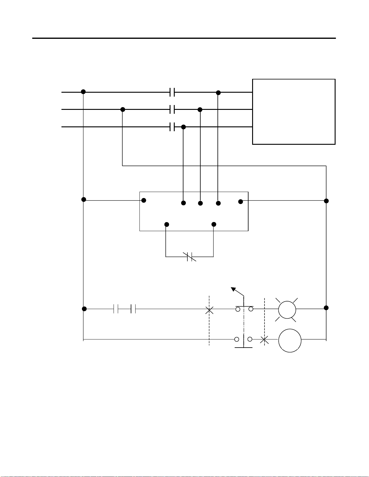
Figure P.1 Typical SLS System Layout
IC
Preface 3
INCOMING
LINES
MOTION BUS
OR
HAZARD
PVSR
IC
SLS SW
PVSR
OFF
ON
SAFE
IC
Publicatio n 1000-UM00 1B-US-P - July 20 00
Page 10
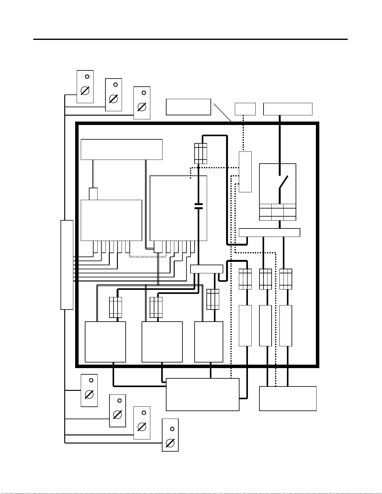
Preface 4
Figure P.2 Typical SLS System Layout
MAIN
ENCLOSURE
PLC
GRD INCOMING LINES
P
E
MAIN
DISC
SLS BOX
SLS EXPANSION
BOX
T
O
S
L
S
S
W
I
T
C
H
E
S
DRIVE DRIVE DRIVE
Publication 1000-UM001B-US-P - July 2000
TO MOTION BU S ON
MACHINE OR HAZARD
S
T
A
R
T
E
R
S
T
A
R
T
E
R
TO NON-MOTION BUS
ON MACHINE OR
NON-HAZARD
S
T
A
R
T
E
R
Page 11

Preface 5
Application
Specifications
The SLS is an isolation system designed to provide disconnection and
isolation. This means that the SLS provides the isolation necessary for work on
machine elements electrically powered through the SLS and for work on the
electrical equipment powered by SLS. Howeve r, the forgoing speaks to the
capability of the SLS, not necessarily its use as assigned by management for a
given purpose.
Since the SLS illuminates the SAFE light, it is imperative that the SLS be
applied only where it disables all forms of energy and after a risk analysis has
been performed.
A. Electrical Ratings
• Supply Voltage 480V, 60 Hz and 400V, 50 Hz
• Contactor Ampacity 30, 85
(in conformance with clause 5.7.1 of NFPA 79: 1997, and
clause 4.3.2 of EN 602 04 -1: 1997)
B. Estimated system life
• SLS box
– Electrical 1,000,000 operations
– Mechanical 10,000,000 operations
• SLS switch
– Electrical 200,000 operations
– Mechanical 200,000 operations
C. Environmental
• Storage temperature –30…+85°C
• Operating temperature, Ambient –10…+40°C
• Relative humidity, Non-Condensing 90% RH
D. Electromagnetic Interference
Compliant with EMC Directives
E. Reliability
Syste m re li abilit y is in dicate d by F M E A an a ly s is.
F. Safety Lo ckout Sys t em
Certified by TUV (Northbrook, IL) for category 4 EN 954-1: 1996, and
EN 60204-1
Publicatio n 1000-UM00 1B-US-P - July 20 00
Page 12

Preface 6
G. Construction
The SLS box enclosure is primarily provided to prevent tampering with
the SLS components and cir c uitry and, as such, is designed and listed
per UL 508A to be inst alled insi de another encl os ur e. The SLS box is
constr u c ted wi th a la rg e tra ns pa re n t viewing wind ow in the cover
necessary to easily observe the status of the LED indicators. Both the
SLS box and the SLS switch are provided with special holes placed to
accommodate tamper-resistant sealing.
H. Construction Rating (for SLS switch only)
NEMA4/IP65
Publication 1000-UM001B-US-P - July 2000
Page 13

Chapter
Installation Instruc tio ns
A. The SLS box enclosure has no environmental rating. Its purpose is to
prevent tampering with the safety system and allow viewing of the
components. The SLS box shall be mounted in a parent enclosure of
suitable environmental rating with sufficient space to allow free opening
of its door a nd conv enient wiring of i t s connectors.
B. After installation the SLS system must be tested for proper operation
and certified as such by a SLS trained service technician, who then seals
the SLS box and the SLS switches. The engineer responsible for the
process or machine shall keep a service logbook of this and all future
servicing. Servicing is to be performed only by SLS qualified technicians.
1
C. SLS cable and cable installation specification
1. Cable must be installed so that it is protected from physical damage.
This may require conduit.
2. Cable must have a shield with a drain wire co nn ected to ground at
the SLS box .
3. Cable insulated for 600V is recommended.
4. Cable shall have copper conductors only.
5. Maximum SLS switch circuit length (total length of wire run):
2
#14 AWG (2.5 mm
#16 AWG (1.5 mm
#18 AWG (0.75 mm
6. Individual conductors within a cable shall be color coded or
otherwise clearly marked.
Suggested source and type of cable:
For SLS switches — Alpha wire Xtra-Guard 2 Part #25450/9 for
#14 AWG 0.64" O.D., Part #25440/9 for #16 AWG 0.61" O.D.,
and Part #25430/9 for #18 AWG 0.55" O.D.
(SLS switch cable must not be run with power conductors.)
) = 4600 ft (1403 m)
2
) = 2600 ft (793 m )
2
) = 1300 ft (397 m)
D. SLS box ground bus must be bonded to the system ground bus in the
main enclosure as follows:
1. For 85 A SLS box with Pilz relay (Cat. No. 1000-NXSLSV85) use
2
#8 AWG (10 mm
2. For 30 A SLS box with Pilz relay (Cat. No. 1000-NXSLSV30) use
#10 AWG (6 mm
1 Publicatio n 1000-UM00 1B-US-P - July 20 00
).
2
).
Page 14

1-2 Installation Instructions
Note: If the Class J fuses protecting the SLS box are smaller than that
specified, the equipment grounding conductor may be reduced to that as
shown in Tab le 25 0- 95 of the N E C.
E. This SLS box has Harting connectors for four SLS switches with safe
light (Cat. No. 1000-NXSLS). If less than that fou r are needed for an
installation, jumper out the unneeded SLS switches in the male end of
the Harting connector. Refer to wiring diagram Y-155798.
Example: If SLS #4 is not needed, remove the hood on the male
Harting SLS connector and install a jumper between pins #3 and #8 on
the insert and install another jumper between pins #4 and #9 on the
insert. This will jumper out the missing SLS switch #4. Re-install the
hood and clamp the male Harting connector back in the SLS #4
position.
F. If an installation requires more than four SLS switches, an expansio n
box(es) can be installed to in crea se the tota l num ber of SLS swi tche s.
Refer to drawings Y-156773 and Y-157131.
G. The SLS enclosure must be bolted to the mounting plate of an enclosure
in the vertical position. Refer to dra wi ng YD-24475 for mounting
dimensions.
H. The SLS box must be protected upstream from the isolation contactor
by a Class J time delay fuse. Maximum available fault current is 42 KA at
480V. In order to ensure IEC 947-4-1 Type 2 or better protection, fuses
are to be sized per NEC Article 430 part D, but shall not exceed the
following:
85 A cont actor size = 100 A max.
30 A contactor size = 30 A max.
I. Power wire size and terminal torque
Table 1.A
SLS Rating Cat. No. Power Wire Size Terminal Torque
30 A with P i lz relay 1000-NXSLSV30 #14…#6 AWG
(2.5…16 mm
85 A with P i lz relay 1000-NXSLSV85 #14…#2 AWG
(2.5…50 mm
2
)
2
)
31 lb-in. (3.5 Nm)
+0%…5%
52 lb-in. (6 Nm)
+0%…5%
J. SLS switch in stallation
1. Mount in the vertical plane per drawing YD-24492.
2. Use conduit and hub or strain relief cord grip.
3. Connect SLS cable to terminal blocks that correspond to the pin
numbers on the Harting connectors per drawing Y-156328.
Publication 1000-UM001B-US-P - July 2000
Page 15

Chapter
2
Commiss ioning Box and Switch
This procedure is to be followed at first time startup and any subsequent SLS
service.
A. Inspection
1. Visually inspect enclosure and components for damage that may
have occurred in installation or shipment. Look for loose wires or
damaged components.
2. For first time ins t allati on, rem o ve adh e sive pro tect iv e pape r cover
from SLS box wind ow .
3. Check incoming and outgoing three phase power lines for proper
selection and siz ing. Sel ect per NEC arti cle 43 0 par t B and size per
NEC tabl e 310-16 , 75°C column. Note that the preferred wire,
MTW, is rated 90°C, but it must be size d per th e 75°C column.
4. Check incoming and outgoing lines along with associated line voltage
control wires that attach to the isolation contactor for proper torque.
Refer to wirin g dia gra m fo r va lue s. Also c heck tha t the lug s do not
crimp down on the wire insulation.
5. Check to see that the proper class J time delay fuse is installed ahead
of the SLS box. Refer to wiring diagram notes and see item H under
“Installation Instructions”.
6. Check to see that the proper size grounding conductor has been
installed between the ground bus in the main enclosure and the
ground bus in the SLS box (refer to item D under “Installation
Instructions”). Refer to NEC Table 250-66 for sizing.
7. Verify that the SLS switches are connected to the SLS box and that
unneeded SLS switches are jumpered out in the Harting connectors
as per item E under “Installation Instructions”.
8. Inspect SLS cable installation for protection against damage. Refer to
item C under “Installation Instructions”.
9. If required, check to see that white phenolic nameplate on the SLS
switch cover is engraved as specified. Also check to see that screws
that secure this nameplate to cover are resealed on the inside of cover
when nameplate is replaced. This is to ensure NEMA Type 4 (IP65)
watertight construction.
10.Verify that the control transformer primary and secondary is
connected per the system voltage per not e #4 on wiring diagram
Y-155798. Refer to Appendix A.
1 Publicatio n 1000-UM00 1B-US-P - July 20 00
Page 16

2-2 Commissioning Box and Switch
B. Verification of SLS operation
1. Turn all SLS switches to the ON position.
2. Check the machine to see that damage or injury will not occur if the
machine is started.
3. En e rgi ze the motion bu s tha t the SLS box con tactor controls.
4. Check for machine operation an d by operating with the norma l start
and stop functions. Check to see that the signals to the PLC and
drive are correct. Leave machine in the stopped mode.
5. Observe LEDs in SL S box for the following conditions:
• Power suppl y DC ON = on.
• VSR — POWER = on .
• Safety relay 1SR — POWER ON, CH1, CH2, K1, K2 = on.
• Safety relay SR — POWER ON, CH1, CH2, K1, K2 = on.
• LED termina l blo cks — PL US = on, 12 = of f, MI NU S = on.
6. All SLS switch SAFE lights should be o ff.
7. Check voltage on secondary of CCT.
8. Measure DC voltage on power supply output. If necessary, adjust to
27V.
9. One at a time, check the operation of each SLS switch by turning it
to the OFF position. Then check for the following:
• SAFE light on.
• IC dropped out.
• 1CR dropped out (refer to cross bar).
• Safety relay dropped out, LED — POWER ON = on, CH1, CH2,
K1, K2 = off.
• VSR indicates saf e condit io n. LE D — POWER = on, six phase
voltages = off.
• LED T.B. — PLUS = on, 12 = on, MINUS = on
Publication 1000-UM001B-US-P - July 2000
C. To provide an indicat ion of tamper in g, seal th e SLS box, the
SLS switches and the Harting connectors with a tamper-resistant
indicating seal. There are holes in the right hand side of the enclosures
for this and in the Harting connectors.
D. A service log shall be kept for each SLS box that keeps track of the
following:
1. Serial number of SLS box
2. Date of commissioning
3. Name of SLS commissioning technician
4. Name of the SLS service technician
5. Description of service performed
6. Date of ser vi ce
Page 17

Component Function and
Chapter
3
Operational Procedure
The machine operat or shou ld not use the SLS to perfor m a norm al stop
function. The SLS should only be used to isolate the system. Machine access is
allowed only after the SLS switch is locked and tagged in the OFF position and
the white SAFE light is illuminated to verify that the system is indeed isolated.
If the white SAFE light fails to illuminate when the SLS switch is turned to the
OFF position, the machine cannot be considered isol ated nor safe. The
operator should not enter the machine, but should contact a SLS qualified
service technician.
Description
Table 3.A SLS Box
Component Cat. No. Source Description Repairable Function
Enclosure 32267-121-51 Allen-Bradley See-through cover Provides segregation and
protection of the SLS
components.
Mounting plate 32267- 122-02 Allen-Bradley Mounts equipment.
Control
transformer
Primary fuse block 1492-FB2C30-L Allen-Bradley Class CC rejection type
Primar y fuses KLDR Allen-Bradley
Second ary fuse
block
Second ary fuse KLDR Allen-Bradley
Power su pply PS5R-C/50W 24 V IDEC Current limiting 24VDC
Safety contactor 100S-C85D04C Allen-Bradley 85 A IEC safety contactor,
B075-1017-GA Micron 480/400 – 120/110V No Provides 120V for control circuit.
No Secures fuse and indicates
with blown fuse indication
Class CC fuse No Protec ts CCT primary.
or Littlefuse
1492-FB 1C30-L Allen-Bradley Class CC rejection type
with blown fuse indication
Class CC fuse No Protec ts CCT sec ondary.
or Littlefuse
with LED
120V coil
No Secures and indicates status.
No Provides current limited 24V DC
No Provides isola tion and s tatus
status.
for SLS circuit.
throug h N.C. pos itive guid ed
auxiliary.
2 N.O. auxiliary 100-SA20 Allen-Bradley 2 N.O. auxiliary No Provides control circuits with
positive guidance and
monito ring of power poles.
Surge suppressor 100-FSC280 Allen-Bradley 120V RC type No Absorbs coil spikes.
1 Publicatio n 1000-UM00 1B-US-P - July 20 00
Page 18

3-2 Operational Procedure
Table 3.A SLS Box (Cont inued)
Component Cat. No. Source Description Repairable Function
Pilz relay PU3Z 24VDV Pilz Voltage supervision and
conta c to r mo nitori ng
safety relay
No Monitors position of contactor
and voltage on lo ad side of
contactor.
Safety relay SR 700-ZBL220Z24 Allen-Bradley 24V safety relay No Checks for cable integrity and
for oper ation of the SLS swi tch.
Safety relay 1SR Allen-Bradley 24V safety relay Y es Serves as E-stop, pilot relay, and
PLC interface.
1CR 700-CF 220DJ Allen-Bradley 24VDC control relay Yes Keeps safe light ou t if the SR
safety relay faul ts.
Protective cover 100-SCCA Allen-Bradley Protective cover No Prevents manual operation.
T erminal blocks 1492-H1 Allen-Bradley Terminal blocks No Provides connections.
LED terminal
blocks
Harting connectors See Ren ewal Parts
1492-HM2V24 Allen-Bradley LED terminal blocks No Provides indication of voltage
presence.
Harting Plug-in connectors Yes Provides quick connection and
List
indicat ion of tampering i f
sealed.
Table 3.B SLS Switch
Component Cat. No. Source Description Repairable Function
Enclosure 32267-132-51 Allen-Bradley NEMA Type 4 SS
enclosure
Provides prot ection fo r SL S
components. Allows for tamper
indication if sealed.
Mounting plate 32267-13 3-01 Allen-Bradley Mounts components
Operat i n g handle 1 94 R -HS 4 Al len-Brad l e y Lockable position
indic at i n g operati ng
handle
No Operat es and pro vi des for
lockout. Enclosure cannot be
opened w hen locked out.
Pilot light 800H-QR24W Allen-Bradley White 24V DC pilot light Yes Signa ls SAFE.
SLS swit ch 194E-A25-1753 Allen-Bradley 3-pole disconnect switch No Provides redun dant sign al
throug h safety relay .
SLS switch
194E-A-P11 Allen-Bradley Auxiliary cont act No Provides SLS status to PLC.
auxiliary contact
Publication 1000-UM001B-US-P - July 2000
Page 19

Operational Procedure 3-3
Servicing
A. Servicing is only to be performed by qualified SLS technician.
B. Due to the nature of this controller and the type of equipment used,
most all components are deemed non-repairable and should be replaced
(not repaired) if they are not functioning properly.
C. Refer to Allen-Bradley wiring diagram Y-156594. This is a schematic for
the 700-ZBL220Z24 and should aid in further understanding of the
operation of the SLS switches and the safety relays. Refer to
Appendix A.
D. Refe rence to renewa l par ts list.
For renewal parts identification and placement refer to Allen-Bradley
docume nt #4 91 03-063-01 (SLS box) and #49000 -064-01
(SLS switch). Refer to Appendix A.
E. Refer to Alle n- B ra d ley d raw a ing Y-1563 86 for test set-up.
F. The entire SLS box may be returned to the factory for repair and/or
testing. Consult your local Allen-Bradley Sales Office regarding a
Product Service Report (PSR) to initiate a factory repair.
Publicatio n 1000-UM00 1B-US-P - July 20 00
Page 20

3-4 Operational Procedure
Notes:
Publication 1000-UM001B-US-P - July 2000
Page 21

Chapter
4
SLS Sequence of Operation
The following is the sequence of operation for the SLS box and the SLS switch
as shown on Y-155798 Rev. M and Y-156328 Rev. B. The intention is to
provide an unde rs tan din g of circuit operation and equ ipm ent f unc tio n. Thi s
will be an aid in troubleshooting because if the sequence stops or is
incomplete, the suspected part or failure may be narrowed down and
identified. Assumptions are made that the SLS has been installed properly, no
fuses are blown, power is on, all equipment is functioning correctly and all SLS
switches are in the ON position
A. Status
1. IC is ope n .
2. Power supply LED is on.
3. Pilz PU3Z powe r L E D on.
4. All SLS switch SAFE lights are off.
5. Al l safety re la y L E Ds ar e o n.
6. 1CR is energized (refer to cross bar).
7. Blown fuse pilot lights are off.
8. TB LEDs between + and – are on.
B. The remote 24V DC signal is applied to 1SR at TB#34 and TB#35
causing it to close the circuit between wires #4 and #5.
C. Since the safety relay 1SR is energized and its contacts between #13 and
#14 are closed, IC will be energized, actuating the IC auxiliary contacts
and sending pow er to th e mo ti on bu s.
1 Publicatio n 1000-UM00 1B-US-P - July 20 00
Page 22

4-2 SLS Sequence of Oper at io n
D. If an operator moves the SLS switch from ON to OFF, the following
will happen:
1. The safety relay circuit between terminals S10 and S11, and S21 and
S2 will open up to de-energize the safety relay, causing the safety
contacts terminals #13 and #1 4 betw een wires #1 and #3 to ope n
up. In addition, safety relay auxiliary contacts between terminals #33
and #34 and #43 and #44 will open dropping out 1CR. This will
cause IC to open up.
Note: If one of the contacts on the SLS switch does not open, or if
there is a short in the cable to the SLS switch, only one of the safety
relay contacts K1 or K2 will drop out IC. But, the safety relay will
lock up and not allow a re-start. Now, since one of the safety relay
auxiliary contacts K1 or K2 will remain closed, 1CR will remain
energized, preventing the SAFE pilot light from illuminating. Also, if
the contacts IC and 1CR between terminals S41 and S42 on the
safety relay have not re-closed, the safety relay will not allow a restart.
2. After IC has dropped out, the VSR will check for voltages greater
than 10V on the load sid e of IC throug h it s redun d an t and bro ken
wire sensing circuit. The VSR will also check to see that the N.C.
positively guided auxiliary contact between wire #7 and #8 on IC is
closed. If these two conditions are met, the VSR will close the safety
contac ts between its te r m in al s #1 3 and #14 .
3. Since the auxiliary contact of IC between ++ and wire #10 is closed,
the 1CR contact between wires #10 and #11 is closed, the safety
contacts between wire #11 and #12 are closed, and the SLS switch
contact between wire #12 and the SAFE pilot light is closed, the
SAFE pilot light will illuminate. The TB led between wire #12 and –
is on.
Publication 1000-UM001B-US-P - July 2000
E. The SAFE pilot light will not come on with the SLS switch in the off
position if:
1. The VSR detects a voltage greater than 10V on the load side IC.
2. The VSR detects that the positively guided N.C. auxiliary IC contact
between wires #7 and #8 has not re-closed.
3. A safety rela y aux ilia ry contact does not allow 1C R to drop ou t and
close circuit between wires #10 and #11.
4. The IC auxiliary contact between wires PLUS and #10 does not
re-close.
Page 23

SLS Sequence of Operati on 4-3
F. If the SLS switch is moved back to the ON position the following will
happen:
1. The SLS switch contacts between the safety relay terminals S10 and
S11, and S21 and B2 will close to energize the safety relay. This
causes the safety contacts between terminals #13 and #14 between
wires #1 and #3 to close.
Note: The SLS switch contacts must close at approximately the same
time or the safety relay will lock up. This may denote an SLS switch
or cable failure. Also, the contacts IC and 1CR between terminals S41
and S42 must be closed or the safety relay will not energize. This may
indicate a failure of IC, 1CR, the SLS switch or the cable. Plus, safety
relay auxiliary contacts between terminals #33 and #34, and #43 and
#44 will close energizing 1CR.
2. Since 1SR between wires #4 and #5 is closed along with 1CR
between wires #3 and #4, and the safety relay SR output contacts
between terminals #13 and #1 4 are also closed, IC will close its
output po wer con ta cts .
3. The PVSR will detect a voltage and see that the circuit between
terminals Y4 and Y5 is open, causing the safety contacts between
terminals #13 and #14 PVSR t o open.
4. All contacts in series with the SAFE light should now be open and
the SAFE light will now be off. The TB led between
wire #12 and – will be off.
Publicatio n 1000-UM00 1B-US-P - July 20 00
Page 24

4-4 SLS Sequence of Oper at io n
Notes:
Publication 1000-UM001B-US-P - July 2000
Page 25

Chapter
Troubleshooting Guide
Troubleshooting Guide
Table 5.A SLS Box
Problem Component Possible Cause Check Suggested Action Repairable?
5
•
Low voltage on
secondary
•
Low voltage on
primary
High voltage on
secondary
Blown fuse
indicated
Blown fuse
indicated
Low DC voltage on
load side
Does not pick up Contactor Low voltage Control voltage — —
Control
transformer
Primar y fuses Overlo ad or short
Second ary fuse Overlo ad or short
Power su pply Overload, low
Loose
connections,
System voltage
Primar y w ired
wrong
in CCT
in CCT
voltage on AC
side
Open coil Flash light coil Replace entire assembled
Open in coil
circuit
Foreign material
jam
Primar y w ired f or pr op er
voltage
Voltage on input Replace if nothing suspicious
For correct wiring or
fault in control circuit
For correct wiring or
fault in control circuit
Adjus t ou tput volt age,
Check CCT voltage
output.
Entire coil circui t — —
— Replace entire assembled
Replace if nothing suspicious
found.
found.
Replace C CT if necessary and
install correct size fuse as
shown on the wiring diagram .
Replace C CT if necessary and
install correct size fuse as
shown on the wiring diagram .
Replace if defec tive. No
contactor.
contactor.
No
No
—
—
No
No
Does not drop out Welded contact
or fore ig n
material jam
Contin uity or
non-operation
Safety contact s
between termin al
#13 and #14 will
not close and there
is no voltage on
load side of
conta c to r and IC
auxiliary is closed
1 Publicatio n 1000-UM00 1B-US-P - July 20 00
Auxiliary contacts — Resistance of contacts
VSR Bad relay Refer to VSR literature
Coil voltage must be
zero.
with wires removed
and LEDs on front of
VSR for status.
Replace entire assembled
contactor.
Auxiliary contacts are locked
on the con tactor re pl a c e entire
assembled device.
Replace VSR. No
No
No
Page 26

5-2 Troubleshooting Guide
Table 5.A SLS Box (Continued)
Problem Component Possible Cause Check Suggested Action Repairable?
Safety contact s
between terminals
#13 and #14 will
not clos e
Safety relay SR Bad SLS switch SLS switch Replace SLS switch. No
Fault, opens or
SLS cable Repair or replace cable. No
short in SLS
cable
1CR jammed on 1CR for operation Replace if necessary. No
IC jammed on For operation Replace entire contactor ass’y. No
Power circuit to
Power LE D off Reset powe r supply. —
safety relay open
Failed safety
LEDs du ring operation Repla ce. No
relay
Safety relay 1SR Power circuit to
Power LE D off Reset powe r supply. No
safety relay open
Failed safety
LEDs du ring operation Repla ce. No
relay
Won’t pick up 1CR Open coil Flash light coil Replace. No
Open cir cuit to
—— —
coil
Welded contacts — Replace. No
Won’t drop out Welded contacts — Replace. No
Foreign material
—Replace. No
jam
Publication 1000-UM001B-US-P - July 2000
Page 27

Troubles hooting Guide 5-3
Table 5.B SLS Switch
Problem Component Possible Cause Check Suggested Action Repairable?
Does not
illuminate with all
other circuitry
checking OK
Contacts do not
operat e properly
Contacts do not
operat e properly
Pilot light Bu rned out bulb
SLS switch Bad switch Continuity and operation Replace. No
SLS switch
auxiliary contact
SLS Test Procedure
Connections Replace bulb.
Loose
connections
Handle
mechanism
Bad contact Continuity and operation Replace. No
For operation Replace. No
Tighten co nnectio ns.
Yes
If an SL S box nee ds to be removed f rom the main control panel, it can be
tested as follows.
Wiring diagram: Y-155798 Rev. M = SLS box
Y-156328 Rev. B = SLS switch
Y-156386 Rev. B = test procedure control panel
In addition to the normal Allen-Bradley test procedure, the following should
also be done:
1. Connect test control pan el per Y-1 56 38 6 Rev. B at PLC conn ector and
power test panel with 24V D C sepa ra te con trol .
2. Connec t four SL S switches wired per Y- 156328 Rev. B.
3. Apply 480V or 400V three-phase to line side of isolation contactor.
4. Turn the four SLS switches to ON position.
5. Energize 1SR with selector switch on test control panel.
6. Observe all LEDs in SLS box for condition. Observe pilot lights on test
control panel for condition. SR, 1SR, IC, and 1CR should be energized.
7. All SLS switch SA F E lights sh ould be of f .
8. Measure DC voltage on power supply output. If necessary, adjust to
27V.
9. Check voltage on secondary of CCT.
Publicatio n 1000-UM00 1B-US-P - July 20 00
Page 28

5-4 Troubleshooting Guide
10. One at a time, check operation of SLS switches by turning to OFF
position, and check for the following:
a. SAFE light on.
b. IC dropped out.
c. 1CR drop ped out.
d. Safety relay SR dropped out
e. VSR indicates safe condition.
11. VSR voltage sensing broken wire d etect ion test.
a. Wit h pow er off, remove one voltage-s ens in g wi re from the VS R.
Then, with all SLS switches in the ON position, apply power and
turn a SLS s witch off. The resu lt should be that the sa f e light does
not illuminate (after cycling an SLS switch) and the system fault LED
is on. The VSR voltage hazard LED will now turn on. Turn power
off, reconnect voltage sensing wire and repeat check with the VSR
redundant voltage sensing circuit.
b. Each separately, do the same test with the two N* circuits. (No initial
fault on VSR, only when the SLS switch is turned to off does the
system fault light come on.)
12. Safety relay cable shorting checks
a. With all pow e r off, instal l a shorting jum per on All en- Bra d ley safety
relay 700-ZBL between t ermina l s S10 and S11. Then po wer up th e
system with all SLS switches in the ON position. Turn a SLS switch
to the OFF po s ition. The SAFE light should not come on. Observe
that CH2 and K1 LEDs are off on the safety relay. Turn off all power
and remove shorting jumper.
b. With all power off, instal l a shorting jum per on All en- Bra d ley safety
relay 700-ZBL between terminals S21 and B2. Then power up the
system with all SLS switches in the ON position. Turn a SLS switch
to the OFF po s ition. The SAFE light should not come on. Observe
that CH1 and K2 LEDs are off on safety relay. Turn off all power
and remove shorting jumper.
Publication 1000-UM001B-US-P - July 2000
Page 29

Troubles hooting Guide 5-5
13. IC contactor m on ito rin g te st.
a. With all power off disconnect wire #7 on the IC auxiliary terminal
#81.
b. Apply power with all SLS switches in the ON position. Turn one SLS
switch to OFF. The safe light should not come ON because the VSR
contacts K2 and K1 between terminals #1 3 an d #1 4 s hould not
close. The VSR will not show a fault light.
c. Turn off power and reconnect wire # 7 at terminal #81 on the IC
contact or auxiliary.
d. Apply power and cycle the 4 SLS switches to confirm system
operation.
14. Voltage sensing test. The object is to determine whether the VSR
contacts K2 and K1 between terminals #13 and #14 remain open if a
voltage is present on the load side of the contactor.
a. To prepare, remov e 3-pha se power, pri mary and s econda ry fusing
and apply 12 0V to wi re #1 and #2 to power contro l circu it . Also ,
apply 3-ph ase voltage to load side of contactor.
b. All SL S switch es in ON pos ition.
c. Turn SLS switch (s) to off. With voltage above 10V applied to the
load side of contactor, the VSR should show a vol tage ha zard LED
and should not allow a SAFE light to come on.
Test is complete. Disconnect all power, remove metering, remove test
SLS switches, install Harting connectors for shipment, remove test
control panel, re-install primary and secondary fusing, check for loose
connections and check to see if all jumpers are removed.
Publicatio n 1000-UM00 1B-US-P - July 20 00
Page 30

5-6 Troubleshooting Guide
Notes:
Publication 1000-UM001B-US-P - July 2000
Page 31

Appendix
Certification Documentation
A. Listed as an open type controller per UL508A
B. TUV Reinland verification of FMEA = checking condition of the SAFE
light
C. Declaration of conformity = CE marked. Self-certified to meet
EN 60204-1: 1 997
D. SUVA letter stating that MCS control devices 1CR and IC have
positively guided auxiliary contacts that meet the requirements of IEC
947-5-1
A
E. TUV Reinland certified to meet the requirements of category 4
EN 954-1: 1996 in re lationship to the SAFE light
Documents
T able A.A
Description Allen-Bradley Drawi ng Num ber Revi si on
SLS box wiring diagram Y-155798 sheet 1, 2, and 3 Rev. M
SLS box dimension drawing YD-24475 Rev. 5
SLS box renewal parts lis t 49000-063-01 Rev . 3
SLS swit ch wiring dia gram Y-156328 Rev. B
SLS switch dimension drawing YD-24492 Rev. 3
SLS swi t ch renewal parts list 49000 -064-01 Rev . 3
T est procedure wiring diagram Y-156386 Rev. B
Allen-Bradley schemat ic wirin g
diagram for 700-ZBL safety relay
SLS box composi te assembly 49103-588-01 Rev. D
4 SLS switch expansion box Y-1567 73 C onsult your
10 SLS switch expansion box Y-157131
4 SLS dim ension s —
Y-156594 Rev . B
local
Allen-Bradley
Sales Off ice.
10SLS dimensions —
LED exp lanatio n sheet 49000 -082-01 Rev. A
1 Publicatio n 1000-UM00 1B-US-P - July 20 00
Page 32
A-2 Certification Documentation
Diagrams
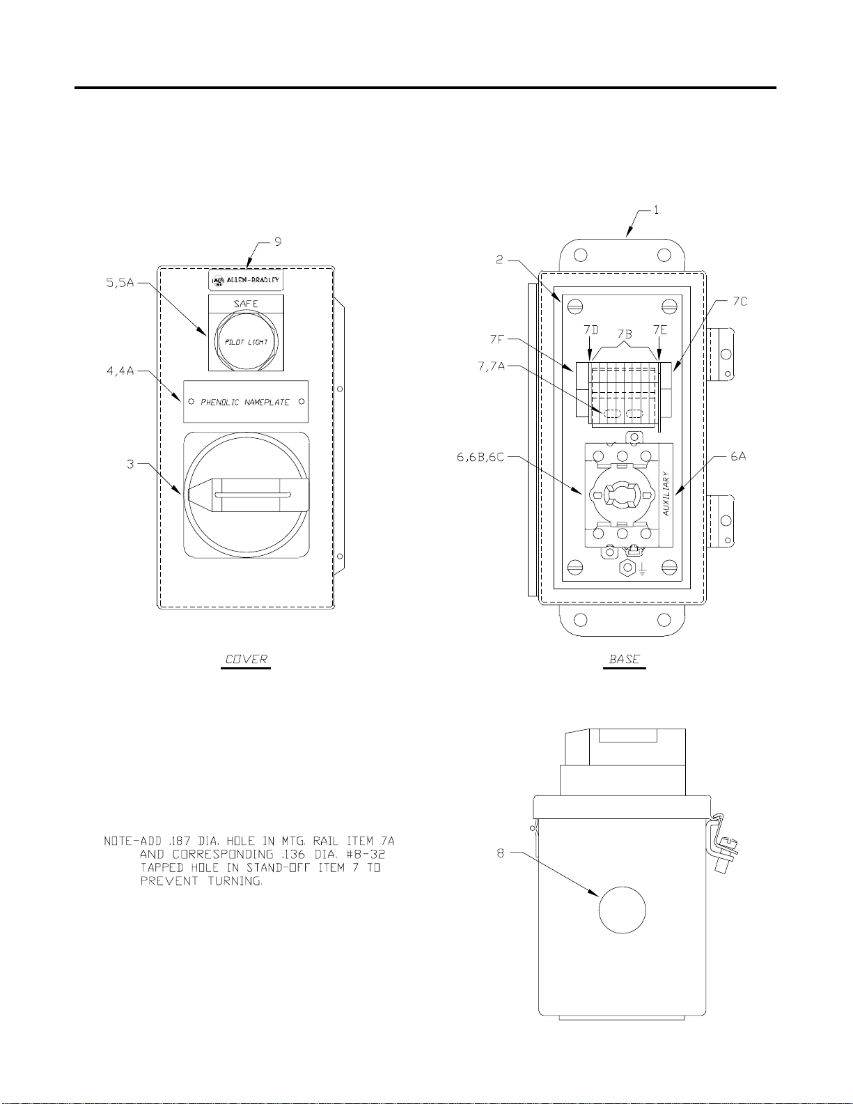
Figure A.1 Bulletin 194E SLS S wi tch Renewal Parts
Publication 1000-UM001B-US-P - July 2000
Page 33

Certification Documentation A-3
T able A.B Bulletin 194E SLS Swit ch R enewal Parts
Item Description Part Number Amount
1 A-B Enclosure 32267-132-51 1
2 A-B Mounting Plate 32267-133-01 1
3 194R Operat ing Hand le — Black 194R-HS4 1
4 Phenolic Na m eplate H-26553 1
4A #4-40 x 0.18 7 Pa n H d. St ain. St. Sc re w 28010- 068-01 2
5 800H Pilot Light 800H-QR24W 1
5A 800H Nameplate Engrv. SAFE 800H-W100E 1
6 194E 25A Load Switch 194E-A25-1753 1
6A 194E Auxiliary Contact 1 N.O. - 1 N.C. 194E-A-P11 1
6B 194E Adapter Kit 194E-G3675 1
6C A-B Operatin g S haft 31013-314-01 1
7 Terminal Block Stand-Off (See Note) 40164-416-01 1
7A T erminal Block Mtg. Rail (See Note) 1492-DR3 1
7B Terminal Blocks 1492-WM3 8
7C Grounding Terminal Block 1492-WMG3 1
7D End Barri e r 42164- 01 7-01 1
7E Partition Plate 1492-PPM3 1
7F End Anchor 1492-E A15 1
8 Cap Plug 28470-007-01 1
9 T rademark Plate H-18742 1
10 Wirin g Diagram Y-156 328 Rev. B 1
Publicatio n 1000-UM00 1B-US-P - July 20 00
Page 34

A-4 Certification Documentation
Figure A.2 Bulletin 100, 85 A SLS Box with Pilz Relay (Ca t. No.1000- N XSLSV8 5)
Renewal Parts
Publication 1000-UM001B-US-P - July 2000
Table A.C Bulletin 100, 85 A SLS Box with Pilz Relay (Cat. No. 1000-NXSLSV85)
Renewal Parts
Item Description Part Number Amount
1 A-B Enclosure 32267-121-51 1
2 A-B Mounting Plate 32267-122-02 1
3 Pandui t Panel Channel E.5x2WH6 1
3A Pandui t Co v e r C.5WH 6 1
4 Heyco Bushing SB-200-26 2
5 Ground Bus N70-12 -1 1
6 Micron Transformer B075-1017-GA 1
7 Prima ry F use Block 1492-FB2C 30-L 1
Page 35

Certification Documentation A-5
Table A.C Bulletin 100, 85 A SLS Box with Pilz Relay (Cat. No. 1000-NXSLSV85)
Renewal Parts (Continued)
Item Description Part Number Amount
8 Primary Fuses Kldr 0.75 A 25183-272-11 2
9 Second ar y F use Block 1492- FB 1C 30-L 1
10 Secondary Fus e Kldr 0.75 A 2 51 83-272-11 1
11 50 W Idec Power Supply PS5R-D24 1
12 100S-85A MCS Contactor 100S-C85D04C 1
12A MCS Surge Suppressor 100-FSC280 1
12B MCS Auxi li ary 2 N.O. 100-SA20 1
13 Pilz Relay PU3Z 24 V 1
14 Timing Relay 700-FEA1SU22 1
15 Safety Relay 440R-ZBL220Z24 2
16 MCS Relay 700-CF220D 1
16A Protective Cover 100-SCCA 1
16B MCS Surge Sup pr ess or 100-FSC280 1
17 Terminal Block s 1492-H1 39
18 End B arrier 1492- N3 6 1
19 End A nchors 149 2-N23 2
20 LED Terminal Bl ocks 1492-HM2V2 4 3
21 End B arrier 1492- NM 40 3
22 Harting Insert Screw 09330102601 4
23 Harting Insert Screw 09330102701 4
24 Harting Hood 093001 00422 4
25 Harting Base 09300100301 4
26 Sealcon CD21AAGY 4
26A Sealcon CD29AAGY 1
27 Harting Male Insert Screw 09330242601 1
28 Harting Female Insert Screw 09330242701 1
29 Harting Hood 093002 40421 1
30 Harting Base 09300240301 1
31 A-B Lo go 40009-100-52 1
32 Wiring Diagram Y-155798 Rev. M 1
33 User Manual Pub. 1000-UM001A-US-P 1
34 LED Explanation Sheet 49000-082-01 1
35 Warning Label 32005-374-01 1
Publicatio n 1000-UM00 1B-US-P - July 20 00
Page 36

A-6 Certification Documentation
Figure A.3 Composite Assem bly of a Bulletin 194E SLS Switch
Publication 1000-UM001B-US-P - July 2000
Page 37

Certification Documentation A-7
T able A.D Composite Assem bly of a Bu lle tin 194E S LS S wi tch
Item Description Part Number Amount
1 Encl. w/Mtg. Plt. (Ref. 32267-132-51)
Eng. Data 1
(Ref. 32267-133-01)
2 194R Operat ing Hand le — Black 194R-HS4 1
3 Phenolic Na m eplate H-26553 1
3A #4-40 x 0.18 7 Pa n H d. St ain. St. Sc re w 28010- 068-01 2
4 800H Pilot Light 800H-QR24W 1
4A 800H Nameplate Engrv. SAFE 800H-W100E 1
5 194E 25A Load Switch 194E-A25-1753 1
5A 194E Auxiliary Contact 1 N.O. - 1 N.C. 194E-A-P11 1
5B 194E Adapter Kit 194E-G3675 1
5C Operating Shaft 31013-314-01 1
6 Terminal Block Stand-Off (See Note) 40164-416-01 1
6A T erminal Block Mtg. Rail (See Note) 1492-DR3 1
6B Terminal Blocks 1492-WM3 8
6C Grounding Terminal Block 1492-WMG3 1
6D End Barri e r 42164- 01 7-01 1
6E Partition Plate 1492-PPM3 1
6F End Anchor 1492-E A15 1
7 Cap Plug 28470-007-01 1
8 Nameplate Stamp w/Serial No. H-25932 1
9 T rademark Plate H-18742 1
10 Wirin g Diagra m Y156328 1
11 Renew al Parts Li st 49000-064-01 1
Publicatio n 1000-UM00 1B-US-P - July 20 00
Page 38

A-8 Certification Documentation
Figure A.4 Composite Assem bly of a Bulletin 100, 85A SLS Box with Pilz Relay
(Cat. No. 1000-NXSLSV85)
Publication 1000-UM001B-US-P - July 2000
T able A.E Composite Assembly of a Bulletin 100, 85A SLS Box with Pilz Relay
(Cat. No. 1000-NXSLSV85)
Item D escription Part Number Amount
1 Encl. w/Mtg. Plt. (Ref. 32267-121-51)
Eng. Data 1
(Ref. 32267-122-02)
2 Nameplate 49103-449-01 1
3 Panel Channel (Panduit E.5x2WH6) Eng. Data 1
3A Cover (Panduit C.5 W H6) Eng. Data 1
4 Heyco Bushing SB-200-26 Eng. Data 2
5 Ground Bus N70-12-1 Eng. Data 1
6 Micron Transformer B075-1017-GA Eng. Data 1
7 Primary Fuse Block 1492-FB2C30-L 1
Page 39

Certification Documentation A-9
T able A.E Composite Assembly of a Bulletin 100, 85A SLS Box with Pilz Relay
(Cat. No. 1000-NXSLSV85) (Continue d)
Item D escription Part Number Amount
8 Primary Fuses K ldr 0.75A 25183-272-11 2
9 Secondary Fuse Block 1492-FB1C 30-L 1
10 Secondary Fuse Kldr 0.75A 2 5183-272-11 1
11 50 W Idec Power Supply PS5R-D24 Eng. Data 1
12 100S-85 A MCS Contactor 100S-C85D04C 1
12A MCS Surge Suppressor 100-FSC280 1
12B MCS Auxiliary 2 N.O. 100-SA20 1
13 Pilz Relay PU3Z Eng. Data 1
14 Timing Relay 700-FEA1SU22 1
15 Safety Relay 4 40R-ZBL 220Z24 2
16 MCS Relay 700-CF220D 1
16A Protective Cover 100-SCCA 1
16B MCS Surge Suppressor 100-FSC280 1
17 Terminal Blocks 1492-H1 39
18 End Ba rrier 1492-N36 1
19 End A nchors 1492-N2 3 2
20 LED Terminal Blocks 1492-HM2V24 3
21 End Ba rrier 1492-NM40 3
22 Harti ng Inser t S crew #09330102601 Eng. Data 4
23 Harting Inser t S crew #09330102701 Eng. Data 4
24 Harting Hood #09300100422 Eng. Data 4
25 Harting Base #09300100301 Eng. Data 4
26 Sealcon #CD21AAGY Eng. Data 4
26A Sealcon #CD29AAGY Eng. Data 1
27 Harting Male Insert Screw #09330242601 Eng. Data 1
28 Harting Female Insert Screw #09330242701 Eng. Data 1
29 Harting Hood #09300240421 Eng. Data 1
30 Harting Base #09300240301 Eng. Data 1
31 A-B Logo 40009-100-52 1
32 UL Label 4000 6-315-01 1
33 Wirin g Diagra m Y-155798 1
34 CE Mark 44006-076-0 5 1
35 Category 4 per IEC 954 Label (Ref. 32005-371-01) Get from Eng. 1
36 Ground Symbol Label Make at Assembly 1
37 Renewal Parts List 49000-063-01 1
38 User Manual Pub.
1
1000-UM001A-US-P
39 LED Explanat ion Sheet 49000-082-01 1
40 Warning Label (Ref.320 05-374-01) Get from Eng. 1
Publicatio n 1000-UM00 1B-US-P - July 20 00
Page 40

A-10 Certification Documentation
Figure A.5 Bulletin 440R-ZBL220 Safety Relay Sc h e matic
Publication 1000-UM001B-US-P - July 2000
Page 41

Figure A.6 Test Panel Schem ati c
Certification Documentation A-11
Publicatio n 1000-UM00 1B-US-P - July 20 00
Page 42

A-12 Certification Documentation
Figure A.7 Safety Lockout System Box Schematic
Publication 1000-UM001B-US-P - July 2000
Page 43

Certification Documentation A-13
Figure A.8 Safety Lockout S ys tem Box Schematic, Continued
Continued on ne xt page
Publicatio n 1000-UM00 1B-US-P - July 20 00
Page 44

A-14 Certification Documentation
Figure A.9 Safety Lockout System Box Connection Diagr am
Publication 1000-UM001B-US-P - July 2000
Page 45

Certification Documentation A-15
Figure A.10 SLS Box with Pilz Re lay , 30A (Cat. No.1000-NXS LSV 30 ) and 85 A (Cat.
No. 1000-N XSL SV85) Dime nsi on Drawi ng
Publicatio n 1000-UM00 1B-US-P - July 20 00
Page 46
A-16 Certification Documentation
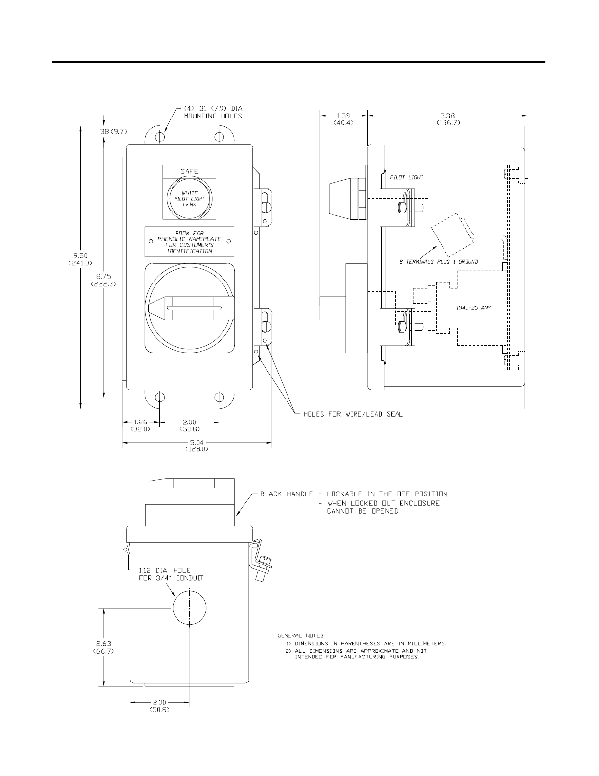
Figure A.11 SLS Switch, NEMA Type 4 Stainless Dimension Drawing
Publication 1000-UM001B-US-P - July 2000
Page 47
Certification Documentation A-17
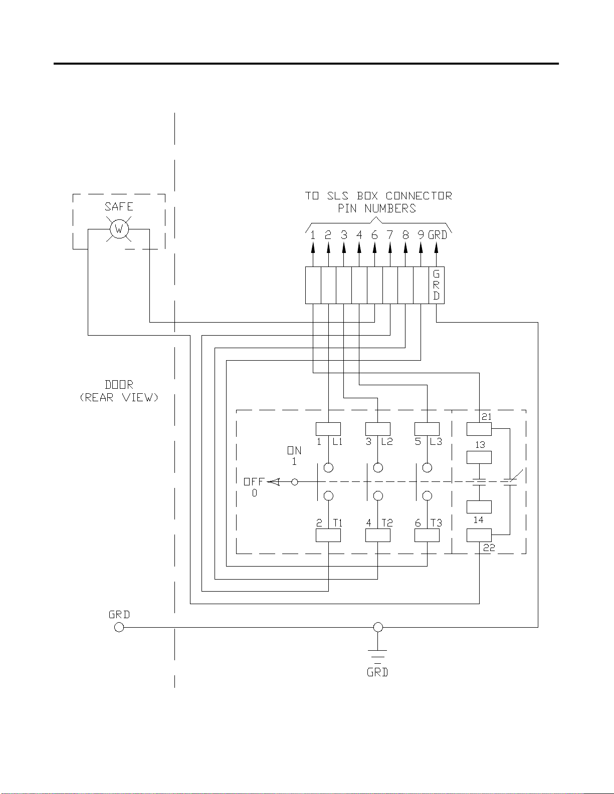
Figure A.12 Safety Lockout System Switch Connection Dia gram
Publicatio n 1000-UM00 1B-US-P - July 20 00
Page 48

A-18 Certification Documentation
Figure A.13 LED Explanation
Publication 1000-UM001B-US-P - July 2000
Page 49

Certification Documentation A-19
Table A.F LED Explanation
Item Description Indicator Explanation
1 Power Supply LED DC on when 120V is applied
2 Control Transforme r
Sec. Fuse
3 Control Transforme r
(2) Pri. Fuses
Blown
Fuse
Blown
Fuse
4 Safety Relay 1SR LED
5 Safety Relay SR LED
6 Pilz Relay PVSR LED
On when fuse is blown
On when fuse is blown
•
POWER on when 24V DC is applied
•
CH1 on w hen circuit S10 to S11 is clos ed
•
CH2 on when circuit S21 to B2 is closed
•
K1 on when internal relay K1 is energized
•
K2 on when internal relay K2 is energized
•
POWER on when 24V DC is applied
•
CH1 on w hen circuit S10 to S11 is clos ed
because all SLS switches are in the ON
position
•
CH2 on w hen circuit S10 to S11 is clos ed
because all SLS switches are in the ON
position
•
K1 on when internal relay K1 is energized
•
K2 on when internal relay K2 is energized
•
POWER on when 24V DC is applied
•
VL1-L2 on voltage L1 to L2 is above 10V
•
VL2-L3 on voltage L2 to L3 is above 10V
•
VL1-L3 on voltage L1 to L3 is above 10V
•
VL1-N on voltag e L1 to ground is abov e 10V
•
VL2-N on voltag e L2 to ground is abov e 10V
•
VL3-N on voltag e L3 to ground is abov e 10V
•
SYSTE M FAILU R E on wh en one of the eight
voltage sensing connections is open or
there is an internal fault i n the PU3Z
•
VOLTAGE HAZARD on when measured
voltage is greate r than 10V
7 ++ Terminal Block LED On when the timer contact is closed
8 – Terminal Block LED On when the 24V DC power supply output is
on
9 12 Terminal Block LED On when IC and 1CR are off, PVSR output is
closed, and an SLS switch is off
10 T iming Relay TR LED On when time delay is complete and output
N.O. contact is closed
Publicatio n 1000-UM00 1B-US-P - July 20 00
Page 50

A-20 Certification Documentation
Notes:
Publication 1000-UM001B-US-P - July 2000
Page 51

References
A. NFPA 70E 1995 edition, NFPA 79 1997 editi on
B. IEC 947, 60204-1, 954-1
Appendix
B
1 Publicatio n 1000-UM00 1B-US-P - July 20 00
Page 52

B-2 References
Notes:
Publication 1000-UM001B-US-P - July 2000
Page 53

Notes:
References B-3
Publicatio n 1000-UM00 1B-US-P - July 20 00
Page 54

B-4 References
Notes:
Publication 1000-UM001B-US-P - July 2000
Page 55

Back Cover
Page 56

Publication 1000-UM001B-US-P - July 2000 2
© 1999 Rockwell International Corporation. Printed in the U.S.A.
 Loading...