

Page 1
RF-TVMP40
TV Wall Mount
For wood-stud and concrete
wall installations
Before using your new product, please read these instructions to prevent any damage.
Safety information and specifications .................................2
Tools needed.................................................................................2
Package contents: parts ............................................................3
Package contents: hardware...................................................4
Installation instructions.............................................................5
Assembly Guide
Page 2
RF-TVMP40 TV Wall Mount
Maximum TV weight: 40 lbs. (18.1 kg)
Minimum TV weight: 18 lbs. (8.2 kg)
Maximum TV Screen size: 55 in. diagonal
Overall dimensions (W × H ):
3.5 x 8.9 in. (9.0 x 22.5 cm)
Wall-mount weight: 18 lbs. (8.2 kg)
We’re here for you
www.rocketfishproducts.com
For customer service, call:
800-620-2790 (U.S./Canada markets)
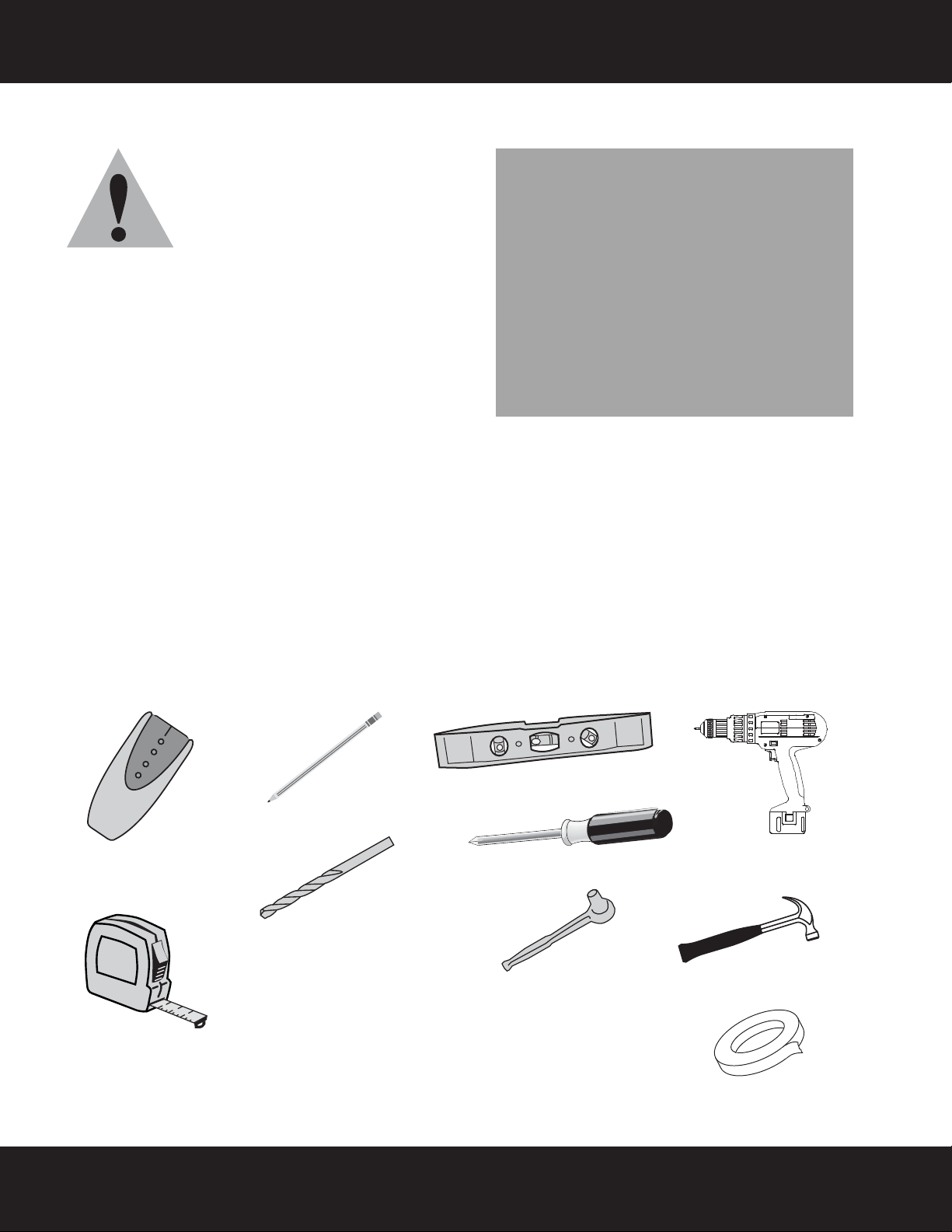
Edge-to-edge
stud finder
Pencil
Level
Phillips screwdriver
Socket wrench with 1/2"
(13 mm) socket.
&
1/4” drive socket wrench
for 8 mm socket (provided)
Measuring tape
Drill
7/32" (5.5 mm) wood drill
bit for wood stud wall
OR
3/8" (9.5 mm) masonry
drill bit (concrete only)
Hammer
Tape
Safety information and specifications
IMPORTANT SAFETY INSTRUCTIONS SAVE THESE INSTRUCTIONS
CAUTION: Do not use this product for
any purpose not explicitly specified by
Rocketfish.
Improper installation may cause
property damage or personal injury. If
you do not understand these directions, or have doubts
about the safety of the installation, contact Customer
Service or call a qualified contractor. Rocketfish is not
responsible for damage or injury caused by incorrect
installation or use.
The included hardware is designed for use on vertical walls
constructed of wood studs or solid concrete. A wood stud
wall is defined as consisting of a minimum of 2x4 wooden
studs (2” wide by 4” deep) with a maximum of 5/8”
drywall. The included hardware is not designed for use with metal studs or cinderblock walls. If you’re uncertain
about the construction of your wall, then please consult a qualified contractor or installer for assistance. For a
safe installation, the wall you are mounting to must support 4 times the weight of the total load. If not, then the
surface must be reinforced to meet this standard. The installer is responsible for verifying that the wall structure
and hardware used in any installation method will safely support the total load.
The weight of your TV must not exceed 40 lbs. (18.1 kg). Rocketfish recommends that the wall be capable of
supporting five times the weight of your TV and wall mount combined, or approximately 200 lbs (90.7 kg).
This product contains small items that could be a choking hazard if swallowed. Keep these items away from
young children!
Tools needed
You will need the following tools to assemble your new TV wall mount:
2
Need help? Call 800-620-2790
Page 3
RF-TVMP40 TV Wall Mount
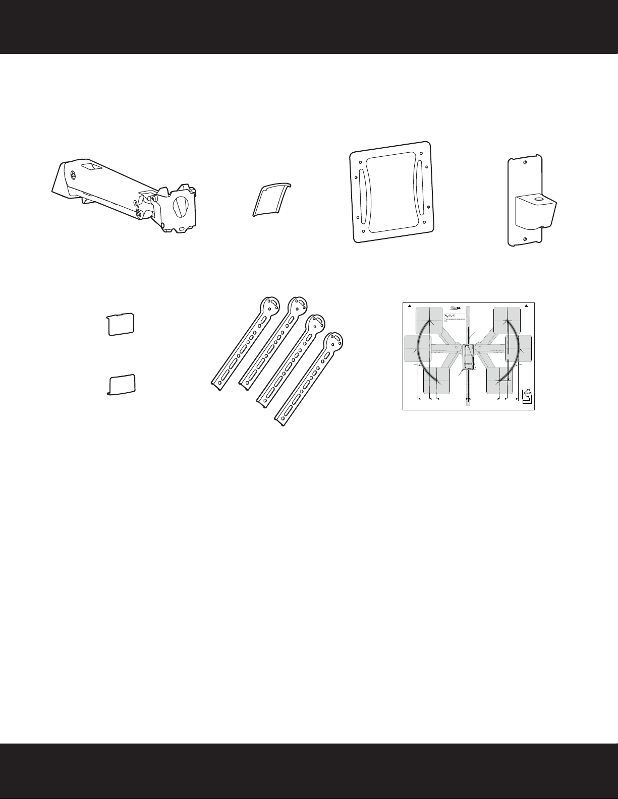
A Arm assembly (1)
D Wall plate (1)
E Wall plate covers (2)
B Rear arm cover (1)
F Spider adapters (4)
C VESA monitor plate(1)
G Template
Package contents: parts
Make sure that you have all the parts necessary to assemble your new TV wall mount:
Top
Dessus
Parte superior
Center of TV Mount Plate
<FR>Center of TV Mount
Plate
<SP>Center of TV Mount
Plate
LEFT TV ARC
“CENTER OF TV” can be placed at any
point along this arc line when the arm is
pushed in against the wall and mounted
at the centerline of your wood stud or
concrete wall.
<FR>LEFT TV ARC
“CENTER OF TV” can be placed at any
point along this arc line when the arm is
pushed in against the wall and mounted
at the centerline of your wood stud or
concrete wall.
<SP>LEFT TV ARC
“CENTER OF TV” can be placed at any
point along this arc line when the arm is
pushed in against the wall and mounted
at the centerline of your wood stud or
concrete wall.
17" (429 mm)
<FR>17" (429 mm)
<SP>17" (429 mm)
Distance between mounting holes and center of TV when in horizontal position and pushed in against the wall.
<FR>Distance between mounting holes and center of TV when in horizontal position and pushed in against the wall.
<SP>Distance between mounting holes and center of TV when in horizontal position and pushed in against the wall.
RF-TVMP40 Template • Gabarit • Plantilla
Tools Needed
Outils nécessaires
Herramientas requeridas
Note
Remarque : Pour une construction à ossature de bois, localiser
Center of TV Mount Plate
<FR>Center of TV Mount
Plate
<SP>Center of TV Mount
Plate
13" (323 mm)
<FR>13" (323 mm)
<SP>13" (323 mm)
d'abord les montants en bois, à l'aide d'un détecteur de montants.
Nota: para la instalación en construcciones de armazón de madera,
primero debe localizar las vigas de madera con un localizador de vigas.
Center of TV Mount Plate
<FR>Center of TV Mount
Plate
<SP>Center of TV Mount
Plate
10" (256 mm)
<FR>10" (256 mm)
<SP>10" (256 mm)
Centerline on Wood Stud or Concrete Wall
<FR>Centerline on Wood Stud or
Concrete Wall
<SP>Centerline on Wood Stud or
Concrete Wall
Arm (Up, left)
<FR>Arm (Up, left)
<SP>Arm (Up, left)
Arm (Center, left)
<FR>Arm (Center, left)
<SP>Arm (Center, left)
Arm (Down, left)
<FR>Arm (Down, left)
7.68" (195 mm)
<SP>Arm (Down, left)
<FR>7.68" (195 mm)
<SP>7.68" (195 mm)
Wall Mount Bracket
<FR>Wall Mount
Bracket
<SP>Wall Mount
Bracket
Mounting Holes
<FR>Mounting
Holes
<SP>
Mounting Holes
Arm (Down, right)
<FR>Arm (Down, right)
<SP>Arm (Down, right)
Arm (Up, right)
<FR>Arm (Up, right)
<SP>Arm (Up, right)
Arm (Center, right)
<FR>Arm (Center, right)
<SP>Arm (Center, right)
Center of TV Mount Plate
<FR>Center of TV Mount
<SP>Center of TV Mount
Vertical Space Requirements 20" (508 mm) + Height of TV*
<FR>Vertical Space Requirements 20" (508 mm) + Height of TV*
<SP>Vertical Space Requirements 20" (508 mm) + Height of TV*
Center of TV Mount Plate
<FR>Center of TV Mount
Plate
<SP>Center of TV Mount
Plate
10" (256 mm)
<FR>10" (256 mm)
<FR>13" (323 mm)
<SP>10" (256 mm)
<SP>13" (323 mm)
Top
Dessus
Parte superior
Plate
Plate
Center of TV Mount Plate
<FR>Center of TV Mount
Plate
<SP>Center of TV Mount
Plate
RIGHT TV ARC
”CENTER OF TV” can be placed at any
point along this arc line when the Arm
is pushed in against the wall and
mounted at the centerline of your
Wood Stud or Concrete Wall.
<FR>RIGHT TV ARC
”CENTER OF TV” can be placed at any
point along this arc line when the Arm
is pushed in against the wall and
mounted at the centerline of your
Wood Stud or Concrete Wall.
<SP>RIGHT TV ARC
”CENTER OF TV” can be placed at any
point along this arc line when the Arm
is pushed in against the wall and
mounted at the centerline of your
Wood Stud or Concrete Wall.
Distance from the Wall
<FR>Distance from the Wall
<SP>Distance from the Wall
13" (323 mm)
17" (429 mm)
<FR>17" (429 mm)
<SP>17" (429 mm)
side
<FR>side
<SP>side
18.19" (462 mm) + Thickness of TV
<FR>18.19" (462 mm) + Thickness of TV
<SP>18.19" (462 mm) + Thickness of TV
24.5" (622 mm) + Thickness of TV
<FR>24.5" (622 mm) + Thickness of TV
<SP>24.5" (622 mm) + Thickness of TV
V1 13-0239
Need help? Call 800-620-2790
3
Page 4
RF-TVMP40 TV Wall Mount
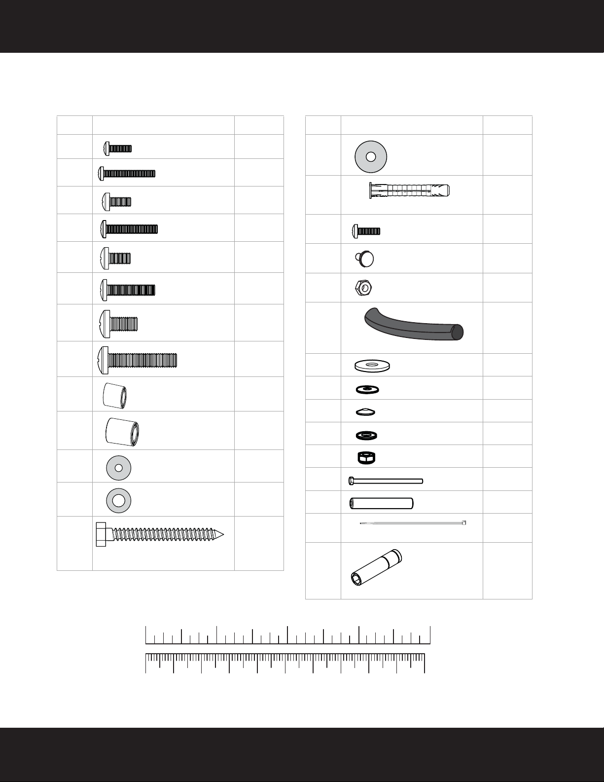
Label Hardware Qty.
M-A 4
M-B 4
M-C 4
M-D 4
M-E 4
M-F 4
M-G 4
M-H 4
M-I 4
M-J 4
M-K 4
M-L 4
W-A 2
M4 × 15 mm screw
M4 × 30 mm
screw
M5 × 15 mm screw
M5 × 30 mm
screw
M6 × 15 mm screw
M6 × 30 mm
screw
M8 × 15 mm
screw
M8 × 30 mm
screw
M6/M8 5 mm spacer
M6/M8 10 mm
spacer
M4/M5 Washer
M6/M8 Washer
5/16" × 2 3/4" (8 mm x 80 mm)
lag bolt
Label Hardware Qty.
W-B 2
W-C 2
P-A 1
P-B 4
P-C 8
P-D 1
P-F 1
P-G 1
P-H 1
P-I 1
P-J 1
P-K 1
P-M 1
P-L 2
P-Q 1
Steel washer
Wall anchor
Phillips screw
Round head screw
Nuts
Cable wrap
65 mm washer
25 mm washer
Spring disc
16 mm bearing
M8 Hex nut
M8 Screw
Tubing
Cable tie
8 mm socket
(requires 1/4” drive)
Package contents: hardware
Make sure that you have all the hardware necessary to assemble your new TV wall mount: TV Hardware Bag
4
10 20 30 40 50 60 70 80 90 1 00mm
1234in
Need help? Call 800-620-2790
Page 5
RF-TVMP40 TV Wall Mount
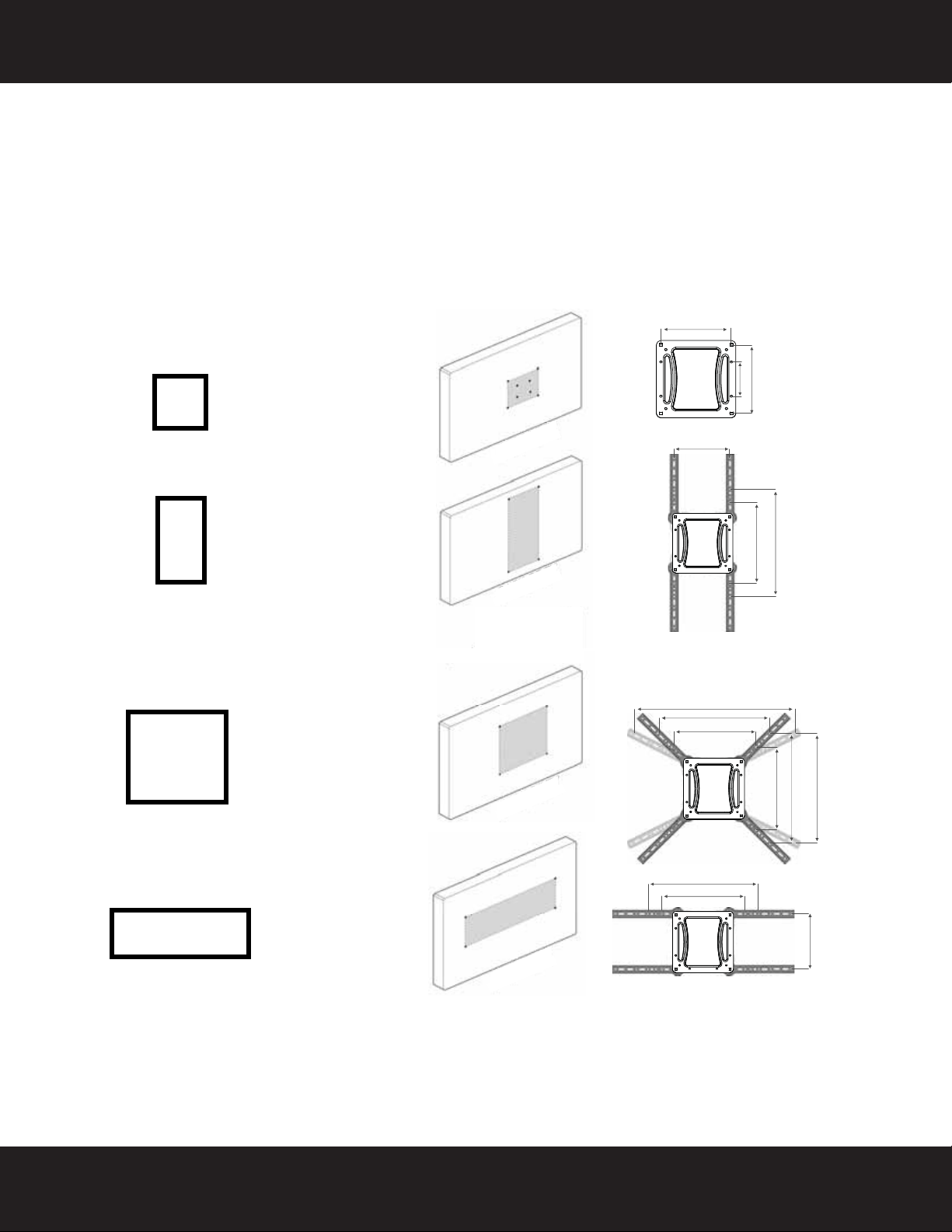
100 x 200 mm
200 x 200 mm
200 x 300 mm
200 x 400 mm
300 x 300 mm
300 x 400 mm
400 x 400 mm
600 x 600 mm
300 x 200 mm
400 x 200 mm
Installation instructions
STEP 1 - Determining your mounting configuration
1 Carefully place your TV screen face down on a cushioned, clean surface to protect the screen from damage
and scratches.
2 If your TV has a table top stand attached, remove the stand. See the documentation that came with your TV
for instructions.
3 Temporarily hold the flat surface of the monitor plate (C) against the back of your TV.
4 Identify the type of mounting configuration by determining if your monitor plate (C) lines up with the screw
holes on the back of your TV or if you will need to install the spider adapters (F).
200mm (7-7/8”)
100mm (3-15/16”)
200mm (7-7/8”)
200mm (7-7/8”)
600mm (23-5/8”)
400mm (15-3/4”)
300mm (11-13/16”)
400mm (15-3/4”)
300mm (11-13/16”)
300mm (11-13/16”)
400mm (15-3/4”)
300mm (11-13/16”)
400mm (15-3/4”)
400mm (15-3/4”)
200mm (7-7/8”)
Need help? Call 800-620-2790
5
Page 6
RF-TVMP40 TV Wall Mount
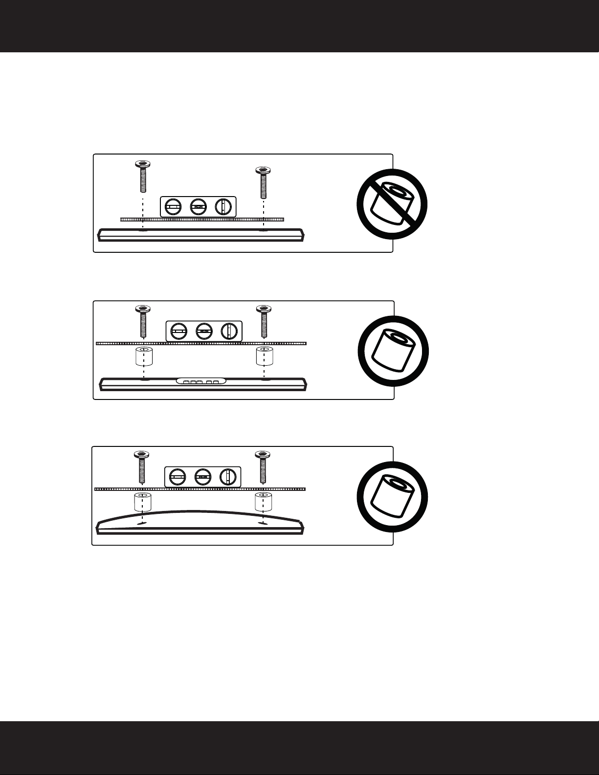
STEP 2 - Determine whether your TV has a flat back or an irregular or obstructed
back
1 With the monitor plate (C) and spider adapters (F) still on your TV, identify which type of back your TV may
have:
• Flat back: The monitor plate and adapters (if necessary) lay flush against the back of your TV and do
not block any jacks. You do not need spacers when assembling the wall mount.
• Obstructed back: The monitor plate and adapters (if necessary) block any of the jacks on the back of
your TV. You will need spacers when assembling the wall mount.
• Irregularly-shaped back: There is a gap between the monitor plate and adapters (if necessary) and
some part of the back of your TV. You will need spacers when assembling the wall mount.
2 Remove the monitor plate and adapters.
6
Need help? Call 800-620-2790
Page 7
RF-TVMP40 TV Wall Mount
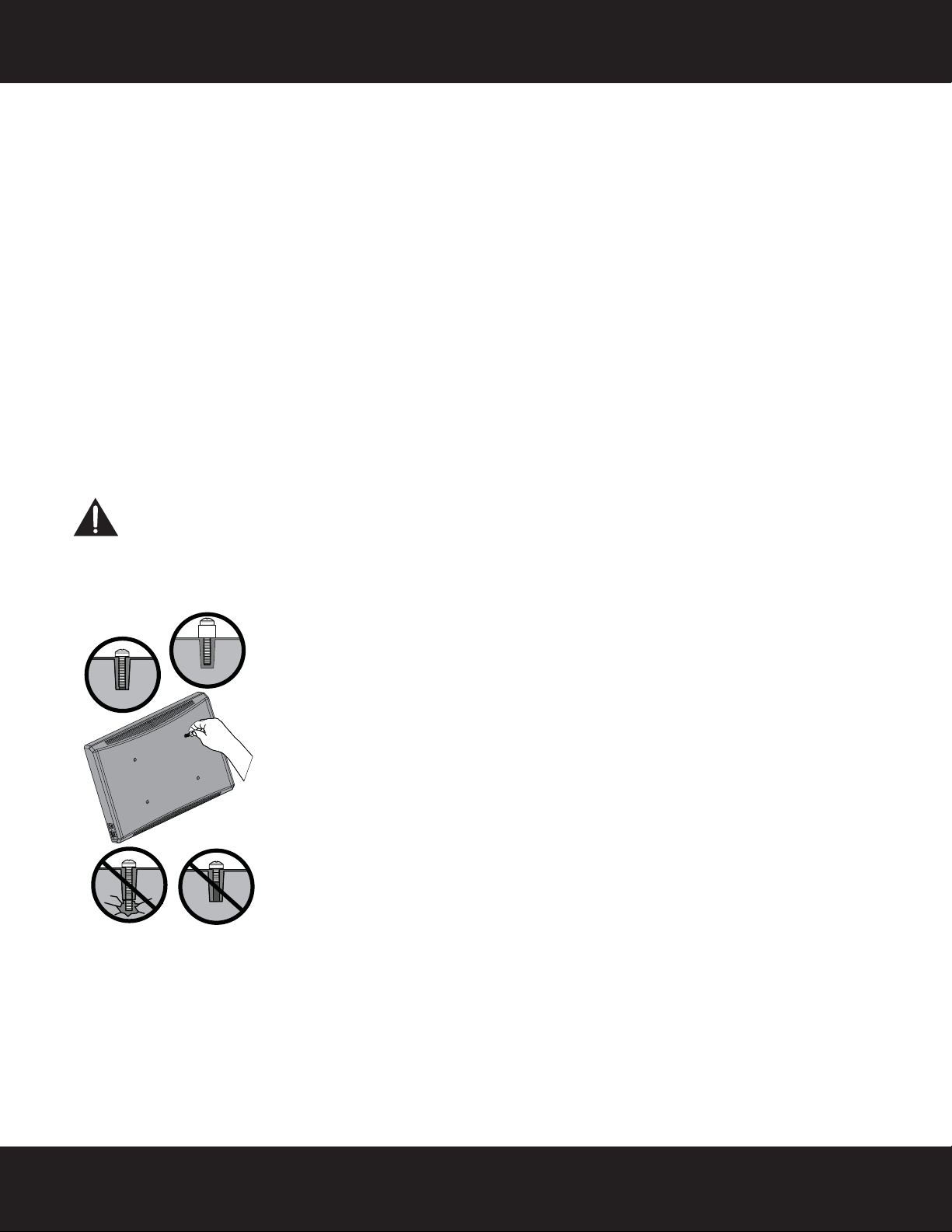
Screw is
too long
Screw fits
correctly
Screw is
too short
STEP 3 - Select screws, washers, and spacers
1 Select the screws for your TV. A limited number of TVs come with mounting hardware included. (If there are
screws that came with the TV, they are usually in the holes on the back of the TV.) If you don't know the
correct length and diameter of the mounting screws your TV requires, test various sizes by hand threading
the screws.
Select one of the following types of screws:
M4 × 15 mm screws (M-A)M6×15mm screws (M-E)
M4 × 30 mm screws (M-B)M6×30mm screws (M-F)
M5 × 15 mm screws (M-C)M8×15mm screws (M-G)
M5 × 30 mm screws (M-D)M8×30mm screws (M-H)
Select one of the following types of washers:
M4/M5 washers (M-K) M6/M8 washers (M-L)
For an irregular or obstructed TV back, use one of the following spacers:
M6/M8 5 mm spacers (M-I) M6/M8 10 mm spacers (M-J)
CAUTION: To avoid potential personal injuries and property damage, make sure that there are adequate
threads to secure the brackets to your TV. If you encounter resistance, stop immediately and contact
customer service. Use the shortest screw available to accommodate your TV. Using hardware that is too
long may damage your TV. However, using a screw that is too short may cause your TV to fall from the
mount.
2 Remove the screws.
For 100 x 200 and 200 x 200 mounting configurations, go to "STEP 4: Option 1 - Attaching the monitor plate to
the TV" on page 8.
-ORFor all other configurations, go to "STEP 4: Option 2 - Attaching the monitor plate with adapters to the TV" on
page 9.
Need help? Call 800-620-2790
7
Page 8

RF-TVMP40 TV Wall Mount
or
or
or
or
or
or
or
or
M-A (4)
M-B (4)
Phillips screwdriver
or
or
M-C (4)
Level
(C) Monitor
plate
or
M-D (4)
or
M-E (4)
or
M-F (4)
M-G (4)
or
M-H (4)
or
M-K (4)
M-L (4)
or
M-I (4)
M-J (4)
STEP 4: Option 1 - Attaching the monitor plate to the TV
1 Align the monitor plate (C) with the screw holes on the back of the TV.
2 Install screws (M-A, M-B, M-C, M-D, M-E, M-F, M-G, or M-H) securely into the four holes in the back of the
TV, using washers (M-K or M-L) and spacers (M-I or M-J) as necessary. Do not over-tighten.
3 Continue to “STEP 5 - Determine wall-mount location” on page 11.
Note: The monitor plate (C) should be level on the back of the TV.
C
M-A M-B M-C
You’ll need
M-K
M-D
M-E M-F M-G M-H
M-I M-J
M-L
8
Need help? Call 800-620-2790
Page 9

RF-TVMP40 TV Wall Mount
X8
C
F
P-B
P-C
200 x 300
200 x 400
300 x 300
300 x 400
400 x 400
600 x 400
300 x 200
400 x 200
P-B (4)
Phillips screwdriver
F Adapters (4)
C Monitor
plate
P-C (8)
STEP 4: Option 2 - Attaching the monitor plate with adapters to the TV
1 Position the four adapters (F) onto the monitor plate (C) to fit your TV mounting configuration determined in
Step 1.
2 Secure the four adapters (F) by using four M5 x 7 mm screws (P - B) and eight nuts (P-C).
You’ l l n ee d
Need help? Call 800-620-2790
9
Page 10

RF-TVMP40 TV Wall Mount
or
or
or
or
or
or
or
or
M-A (4)
M-B (4)
Phillips screwdriver
or
or
M-C (4)
Level
or
M-D (4)
or
M-E (4)
or
M-F (4)
M-G (4)
or
M-H (4)
or
M-K (4)
M-L (4)
or
M-I (4)
M-J (4)
STEP 4: Option 2 - Attaching the monitor plate with adapters to the TV (continued)
3 Align the adapters (F) with the screw holes on the back of your TV.
4 Install screws (M-A, M-B, M-C, M-D, M-E, M-F, M-G, or M-H) securely into the four holes in the back of the
TV, using washers (M-K or M-L) and spacers (M-I or M-J) as necessary. Do not over-tighten.
Note: The bracket assembly should be level on the back of the TV.
5 Continue to “STEP 5 - Determine wall-mount location” on page 11.
C
M-A M-B M-C
You’ll need
M-K
M-D
M-E M-F M-G M-H
UP
F
M-I M-J
M-L
10
Need help? Call 800-620-2790
Page 11

RF-TVMP40 TV Wall Mount
a
b
c
c
17” 17”
Measuring tape
Pencil
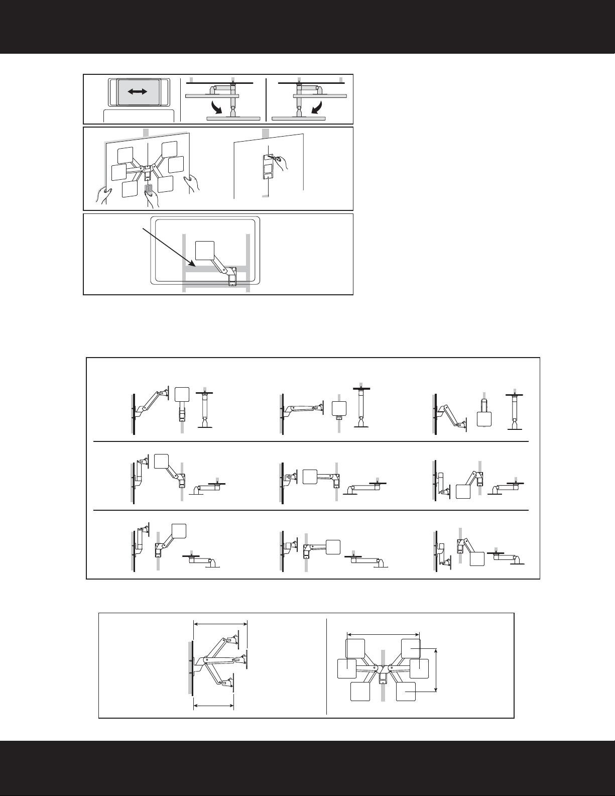
STEP 5 - Determine wall-mount location
Choose the TV location with the arm stowed and extended. Note that the TV will move side-to-side when
pushing it into and pulling it out from the wall as well as lifting it up and lowering it down. This step requires an
understanding of this products Range of Motion (see section RANGE OF MOTION on page 12).
Note:
• For more detailed information on determining where to drill your holes, visit our online height-finder at:
http://mf1.bestbuy.selectionassistant.com/index.php/heightfinder
• Your TV should be high enough so your eyes are level with the middle of the screen. Normally, 40 to 60 inches
from the ground.
When your TV is in a position closest to the wall and the arm assembly is horizontal, the center of your TV will be
17” to the left or the right of the center of the wall plate.
1 Measure the distance from the bottom of your TV to the middle (half of the height of the TV). This is
measurement a.
2 Measure the distance from the floor to where you want the bottom of the TV to be positioned on the wall
when the Arm Assembly is horizontal. Keep in mind that this TV Mount allows for 17" of travel horizontally
and 10" of travel vertically from the center of the wall plate. Your TV should be mounted in a position that
will not cause it to come in contact with furniture, or items placed on top of furniture (like a Blu-ray player or
cable box). This is measurement b.
3 Add a + b. This measurement is the height where you want the center of your TV to be.
4 Measure 17” to the left OR right of the a + b measurement position. This will be the location for the center of
the wall plate. This is measurement c.
5 Use a pencil to mark this spot on the wall.
You’ l l n ee d
Need help? Call 800-620-2790
11
Page 12
RF-TVMP40 TV Wall Mount
front
top
top
Horizontal
studs
If there is no available
stud for the TV location
you want, you can insert
horizontal studs into your
wall at the selected
mounting location.
Arm fully extended from wall
Arm flat against the wall (left)
Arm flat against the wall (right)
Full up
Full up
Full up
side
side
side
front
top
side
front
top
side
front
top
side
front
top
side
front
top
side
front
top
side
front
top
front
top
front
top
Centered
Full down
Centered
Full down
Centered
Full down
Distance from
the wall
side
front
24.5” (622 mm)
+ thickness of TV
18.2” (462 mm)
+ thickness of TV
Horizontal space requirements 34”
(858 mm) + width of TV*
Vertical space
requirements 20”
(508 mm) +
height of TV*
*Assuming mounting holes are centered on TV.
Mounting considerations:
•Wall Mount Bracket MUST be attached to
a stud or solid concrete. DO NOT attach
this product to hollow wall or any other
configuration.
•Make sure that the arm will have desired
unobstructed range of motion: up-down,
side-to-side, in-out (see RANGE OF
MOTION).
•Make sure cables will reach their
destinations with enough remaining
slack to allow Arm full range of motion.
•Use the RANGE OF MOTION illustration
to familiarize yourself with the
movements of this product. Take into
account that the TV will change location
from side-to-side when pulled out from
the wall.
•Use the SPACE REQUIREMENTS
illustration for maximum measurements
of this products full range of motion.
Range of motion:
Space requirements:
12
Need help? Call 800-620-2790
Page 13
RF-TVMP40 TV Wall Mount
Center pencil mark made in
Step 1.
2-3/4 in.
(70 mm)
Edge-to edge
stud finder
W-A (2)
Pencil
Drill
7/32" wood drill bit
1/2" socket wrench
Level
D Wall
plate
G Template
Tap e
W-B Washer
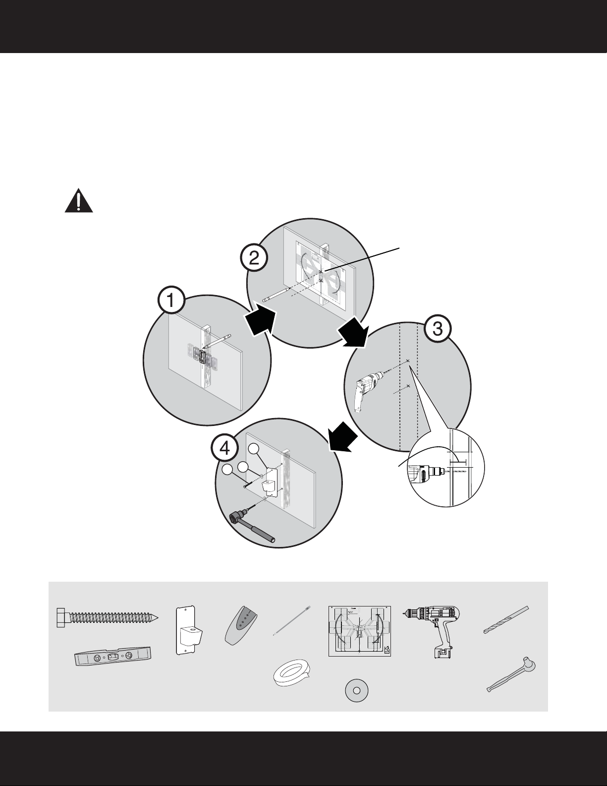
STEP 6 - Option 1: Installing on a wood stud wall
Note: Any wallboard or material covering the wall must not exceed 5/8" (16 mm).
1 Locate the stud. Verify the center of the stud with an edge-to-edge stud finder.
2 Align the wall plate template (G) at the height you determined in the previous step and make sure that it is
level, then tape it to the wall. Use a pencil to mark the lag bolt hole locations (2) on the stud centers. Remove
the wall plate template.
3 Drill pilot holes to a depth of 2-3/4 in. (70 mm) using a 7/32 in. (5.5 mm) diameter drill bit.
4 Align the wall plate (D) with the pilot holes, insert the lag bolts (W-A) through the washers (W-B), then
through the holes in the wall plate, then tighten the lag bolts only until they are firm against the wall plate.
CAUTION: : Avoid potential injuries or property damage!
DO NOT over-tighten the lag bolts (W-A).
You’ll need
Need help? Call 800-620-2790
W-A
D
W-B
Top
Dessus
Parte superior
Center of TV Mount Plate
<FR>Center of TV Mount
Plate
<SP>Center of TV Mount
Plate
LEFT TV ARC
“CENTER OF TV” can be placed at any
point along this arc line when the arm is
pushed in against the wall and mounted
at the centerline of your wood stud or
concrete wall.
<FR>LEFT TV ARC
“CENTER OF TV” can be placed at any
point along this arc line when the arm is
pushed in against the wall and mounted
at the centerline of your wood stud or
concrete wall.
<SP>LEFT TV ARC
“CENTER OF TV” can be placed at any
point along this arc line when the arm is
pushed in against the wall and mounted
at the centerline of your wood stud or
concrete wall.
RF-TVMP40 Template • Gabarit • Plantilla
Note
Remarque : Pour une construction à ossature de bois, localiser
d'abord les montants en bois, à l'aide d'un détecteur de montants.
Nota: para la instalación en construcciones de armazón de madera,
primero debe localizar las vigas de madera con un localizador de vigas.
Center of TV Mount Plate
<FR>Center of TV Mount
Plate
<SP>Center of TV Mount
Plate
Arm (Up, left)
<FR>Arm (Up, left)
<SP>Arm (Up, left)
Arm (Center, left)
<FR>Arm (Center, left)
<SP>Arm (Center, left)
Arm (Down, left)
<FR>Arm (Down, left)
<SP>Arm (Down, left)
Center of TV Mount Plate
<FR>Center of TV Mount
Plate
<SP>Center of TV Mount
Plate
10" (256 mm)
13" (323 mm)
17" (429 mm)
<FR>10" (256 mm)
<FR>13" (323 mm)
<FR>17" (429 mm)
<SP>10" (256 mm)
<SP>13" (323 mm)
<SP>17" (429 mm)
Distance between mounting holes and center of TV when in horizontal position and pushed in against the wall.
<FR>Distance between mounting holes and center of TV when in horizontal position and pushed in against the wall.
<SP>Distance between mounting holes and center of TV when in horizontal position and pushed in against the wall.
Tools Needed
Outils nécessaires
Herramientas requeridas
Wall Mount Bracket
<FR>Wall Mount
Bracket
<SP>Wall Mount
Bracket
Top
Dessus
Parte superior
Centerline on Wood Stud or Concrete Wall
<FR>Centerline on Wood Stud or
Center of TV Mount Plate
Concrete Wall
<FR>Center of TV Mount
<SP>Centerline on Wood Stud or
Plate
Concrete Wall
<SP>Center of TV Mount
Plate
Arm (Up, right)
<FR>Arm (Up, right)
<SP>Arm (Up, right)
Arm (Center, right)
<FR>Arm (Center, right)
<SP>Arm (Center, right)
Center of TV Mount Plate
Vertical Space Requirements 20" (508 mm) + Height of TV*
Arm (Down, right)
<FR>Center of TV Mount
<FR>Arm (Down, right)
<FR>Vertical Space Requirements 20" (508 mm) + Height of TV*
Plate
7.68" (195 mm)
<SP>Arm (Down, right)
<SP>Vertical Space Requirements 20" (508 mm) + Height of TV*
<FR>7.68" (195 mm)
<SP>Center of TV Mount
<SP>7.68" (195 mm)
Plate
RIGHT TV ARC
”CENTER OF TV” can be placed at any
point along this arc line when the Arm
is pushed in against the wall and
mounted at the centerline of your
Wood Stud or Concrete Wall.
Mounting Holes
<FR>RIGHT TV ARC
”CENTER OF TV” can be placed at any
<FR>Mounting
point along this arc line when the Arm
is pushed in against the wall and
Holes
mounted at the centerline of your
Wood Stud or Concrete Wall.
<SP>
<SP>RIGHT TV ARC
”CENTER OF TV” can be placed at any
Mounting Holes
point along this arc line when the Arm
is pushed in against the wall and
mounted at the centerline of your
Wood Stud or Concrete Wall.
Center of TV Mount Plate
Distance from the Wall
<FR>Center of TV Mount
<FR>Distance from the Wall
<SP>Distance from the Wall
Plate
<SP>Center of TV Mount
Plate
10" (256 mm)
13" (323 mm)
17" (429 mm)
<FR>10" (256 mm)
<FR>13" (323 mm)
<FR>17" (429 mm)
<SP>10" (256 mm)
<SP>13" (323 mm)
<SP>17" (429 mm)
side
<FR>side
<SP>side
18.19" (462 mm) + Thickness of TV
<FR>18.19" (462 mm) + Thickness of TV
<SP>18.19" (462 mm) + Thickness of TV
24.5" (622 mm) + Thickness of TV
<FR>24.5" (622 mm) + Thickness of TV
<SP>24.5" (622 mm) + Thickness of TV
V1 13-0239
13
Page 14

RF-TVMP40 TV Wall Mount
2-3/4 in.
(70 mm)
Edge-to edge
stud finder
W-A (2)
Pencil
Drill
3/8" masonry drill bit
1/2" socket
wrench
Level
W-C (2)
Hammer
D Wall
plate
G Temp l ate
Tap e
W-B Washer (2)
STEP 6 - Option 2: Installing on a solid concrete wall
1 Align the wall plate template (G) at the height you determined in the previous step and make sure that it is
level, then tape it to the wall. Use a pencil to mark the lag bolt hole locations (2). Remove the template.
2 Drill pilot holes to a depth of 2-3/4 in. (7 mm) using a 3/8 in. (10 mm) diameter masonry drill bit.
3 Insert the concrete wall anchors (W-C) into the pilot holes and use a hammer to make sure the anchors are
flush with the concrete surface.
4 Align the wall plate (D) with the anchors, insert the lag bolts (W-A) through the washers (W-B), then through
the holes in the wall plate, then tighten the lag bolts only until they are firm against the wall plate.
CAUTION: Avoid potential injuries or property damage!
DO NOT over-tighten the lag bolts (W-A).
You’l l ne e d
Top
Dessus
Parte superior
Center of TV Mount Plate
<FR>Center of TV Mount
Plate
<SP>Center of TV Mount
Plate
LEFT TV ARC
“CENTER OF TV” can be placed at any
point along this arc line when the arm is
pushed in against the wall and mounted
at the centerline of your wood stud or
concrete wall.
<FR>LEFT TV ARC
“CENTER OF TV” can be placed at any
point along this arc line when the arm is
pushed in against the wall and mounted
at the centerline of your wood stud or
concrete wall.
<SP>LEFT TV ARC
“CENTER OF TV” can be placed at any
point along this arc line when the arm is
pushed in against the wall and mounted
at the centerline of your wood stud or
concrete wall.
RF-TVMP40 Template • Gabarit • Plantilla
Note
Remarque : Pour une construction à ossature de bois, localiser
d'abord les montants en bois, à l'aide d'un détecteur de montants.
Nota: para la instalación en construcciones de armazón de madera,
primero debe localizar las vigas de madera con un localizador de vigas.
Center of TV Mount Plate
<FR>Center of TV Mount
Plate
<SP>Center of TV Mount
Plate
Arm (Up, left)
<FR>Arm (Up, left)
<SP>Arm (Up, left)
Arm (Center, left)
<FR>Arm (Center, left)
<SP>Arm (Center, left)
Arm (Down, left)
<FR>Arm (Down, left)
<SP>Arm (Down, left)
Center of TV Mount Plate
<FR>Center of TV Mount
Plate
<SP>Center of TV Mount
Plate
10" (256 mm)
13" (323 mm)
17" (429 mm)
<FR>10" (256 mm)
<FR>13" (323 mm)
<FR>17" (429 mm)
<SP>10" (256 mm)
<SP>13" (323 mm)
<SP>17" (429 mm)
Distance between mounting holes and center of TV when in horizontal position and pushed in against the wall.
<FR>Distance between mounting holes and center of TV when in horizontal position and pushed in against the wall.
<SP>Distance between mounting holes and center of TV when in horizontal position and pushed in against the wall.
W-C
D
W-B
W-A
Top
Dessus
Tools Needed
Outils nécessaires
Herramientas requeridas
Wall Mount Bracket
<FR>Wall Mount
Bracket
<SP>Wall Mount
Bracket
Parte superior
Centerline on Wood Stud or Concrete Wall
<FR>Centerline on Wood Stud or
Center of TV Mount Plate
Concrete Wall
<FR>Center of TV Mount
<SP>Centerline on Wood Stud or
Plate
Concrete Wall
<SP>Center of TV Mount
Plate
Arm (Up, right)
<FR>Arm (Up, right)
<SP>Arm (Up, right)
Arm (Center, right)
<FR>Arm (Center, right)
<SP>Arm (Center, right)
Center of TV Mount Plate
Vertical Space Requirements 20" (508 mm) + Height of TV*
Arm (Down, right)
<FR>Center of TV Mount
<FR>Arm (Down, right)
<FR>Vertical Space Requirements 20" (508 mm) + Height of TV*
Plate
7.68" (195 mm)
<SP>Arm (Down, right)
<SP>Vertical Space Requirements 20" (508 mm) + Height of TV*
<FR>7.68" (195 mm)
<SP>Center of TV Mount
<SP>7.68" (195 mm)
Plate
RIGHT TV ARC
”CENTER OF TV” can be placed at any
point along this arc line when the Arm
is pushed in against the wall and
mounted at the centerline of your
Wood Stud or Concrete Wall.
Mounting Holes
<FR>RIGHT TV ARC
”CENTER OF TV” can be placed at any
<FR>Mounting
point along this arc line when the Arm
is pushed in against the wall and
Holes
mounted at the centerline of your
Wood Stud or Concrete Wall.
<SP>
<SP>RIGHT TV ARC
”CENTER OF TV” can be placed at any
Mounting Holes
point along this arc line when the Arm
is pushed in against the wall and
mounted at the centerline of your
Wood Stud or Concrete Wall.
Center of TV Mount Plate
Distance from the Wall
<FR>Center of TV Mount
<FR>Distance from the Wall
<SP>Distance from the Wall
Plate
<SP>Center of TV Mount
Plate
10" (256 mm)
13" (323 mm)
17" (429 mm)
<FR>10" (256 mm)
<FR>13" (323 mm)
<FR>17" (429 mm)
<SP>10" (256 mm)
<SP>13" (323 mm)
<SP>17" (429 mm)
side
<FR>side
<SP>side
18.19" (462 mm) + Thickness of TV
<FR>18.19" (462 mm) + Thickness of TV
<SP>18.19" (462 mm) + Thickness of TV
24.5" (622 mm) + Thickness of TV
<FR>24.5" (622 mm) + Thickness of TV
<SP>24.5" (622 mm) + Thickness of TV
V1 13-0239
14
Need help? Call 800-620-2790
Page 15

RF-TVMP40 TV Wall Mount
CAUTION! The
bottom nut will turn
when you adjust of
the top nut. DO NOT
apply any tool to the
bottom nut. Serious
damage to the arm
may occur if these
instructions are not
followed.
NOTE: The spring disk (P-H)
must be concave face down for
proper assembly.
D Wall plate (1)
P-K M8 HEX screw (1)
A Arm assembly (1)
E Wall plate
covers (2)
P-M Tubing (1)
Socket wrench
P-F 65 mm
washer(1)
P-I 16 mm
bearing (1)
P-H Spring
disk (1)
P-G 25 mm
washer (1)
P-J M8 HEX nut (1)
STEP 7 - Attach the arm assembly to the wall plate
1 Install the top and bottom covers (E) onto the wall plate (D).
2 Place the tubing (P-M) into the hole in the top of the wall plate (D), then place the 65mm washer (P-F) over
the tubing (P-M).
3 Place the arm assembly (A) onto the tubing (P-M) on the wall plate (D), then install the M8 HEX screw (P-K),
with the 16mm bearing (P-I), spring disk (P-H), and 25 mm washer (P-G)) through the tubing (P-M).
4 Install the M8 HEX nut (P-J) on the end of the M8 hex screw (P-K), then tighten with a socket wrench with a
13 mm deep socket. You can adjust the tension on this bolt to make the TV pivot more or less easily.
P-F
E
A
D
E
P-H
P-M
P-K
P-I
P-G
You’ll need
P-J
Need help? Call 800-620-2790
15
Page 16

RF-TVMP40 TV Wall Mount
HEAVY! You will need
assistance with this step.
Phillips screwdriver
P-A (1)
STEP 8 - Attach your TV to the arm assembly
1 Holding the TV level, with the screen parallel to the wall, connect the monitor plate (C) to the arm assembly
(A), as shown below.
2 Secure with the phillips screw (P-A) through the arm assembly (A) into the monitor plate (C) and tighten the
screw.
A
C
16
P-A
You’ l l n ee d
Need help? Call 800-620-2790
Page 17

RF-TVMP40 TV Wall Mount
P-D Cable wrap (1)
P-L Cable ties (2)
STEP 9 - Installing the cable wrap and cable ties
1 Connect the cable to your TV, then secure the cable to the underside of the arm assembly (A) with two cable
ties (P-L).
2 Install the cable wrap (P-D) on the cables to provide a neater appearance.
You’ll need
P-L
P-D
Need help? Call 800-620-2790
17
Page 18

RF-TVMP40 TV Wall Mount
Increase
If TV weight exceeds product’s
factory setting, it won’t stay up
when raised. To prevent TV from
sagging downward, increase
tension setting.
Decrease
If TV weight is lower than
product’s factory setting, it won’t
stay down when lowered. To
prevent TV from drifting upward,
decrease tension setting.
Adjusting the factory-set tension
1/4” Drive socket wrench (not
provided) w/8 mm socket P-Q
STEP 10 - Adjusting the vertical motion
Important! You will need to adjust this product after installation is complete.
Make sure all your equipment is properly installed on the product before adjusting. This product should move
smoothly and easily through the full range of motion and stay where you set it. If movements are too easy or diffcult or
if product does not stay in desired position, follow the adjustment instructions to create smooth and easy movements.
NOTE: Depending on your product and the type of adjustment, it may take many turns to notice a difference.
Any time equipment is added or removed from this product, resulting in a change in the weight of the mounted load,
you should repeat these adjustment steps to ensure safe and optimum operation.
• To increase or decrease the lift tension, use a 1/4” drive socket wrench with the 8 mm socket (P-Q).
You’ll need
18
Need help? Call 800-620-2790
Page 19
RF-TVMP40 TV Wall Mount
Increase
If your TV moves too easily from
side to side, increase the tension.
Decrease
If your TV doesn’t move easily
enough from side to side,
decrease the tension.
Adjusting the factory-set tension
Socket wrench w/1/2” (13 mm) socket
STEP 11 - Adjusting the setting for pan tension
1 Remove the bolt cover from the adjustment bolt.
2 To increase or decrease the pan tension, use a 1/2” (13 mm) socket wrench.
3 Replace the bolt cover to the adjustment bolt.
You’ l l n ee d
Need help? Call 800-620-2790
19
Page 20

RF-TVMP40 TV Wall Mount
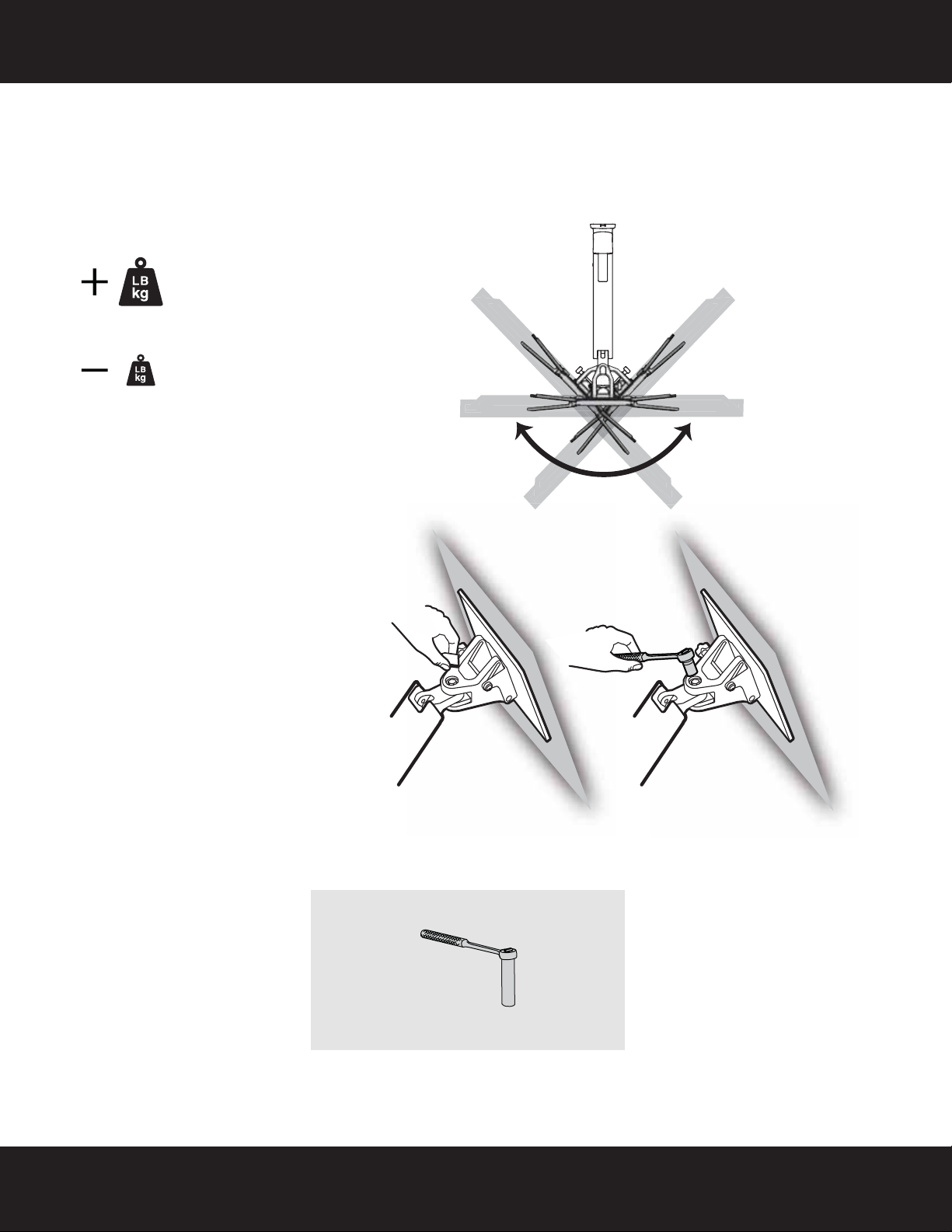
CAUTION! The bottom nut will turn during
adjustment of the top nut; DO NOT apply any
tool to the bottom nut. Serious damage to the
arm may occur if these instructions are not
followed.
Increase
If your TV moves too easily from
side to side, increase the friction.
Decrease
If your TV doesn’t move easily
enough from side to side,
decrease the friction.
Adjusting the factory-set tension
Socket wrench w/1/2” (13 mm) socket
STEP 12 - Adjusting the horizontal movement
1 Lift the arm assembly up to it’s highest point, then remove the rear arm cover (B).
2 To increase or decrease horizontal movement tension, us a 1/2” (13 mm) socket wrench.
3 Replace the rear arm cover.
You’ll need
20
Need help? Call 800-620-2790
Page 21

RF-TVMP40 TV Wall Mount
Increase
If TV weight exceeds product’s
factory setting, it won’t stay up
when raised. To prevent TV from
sagging downward, increase
tension setting.
Decrease
If TV weight is lower than
product’s factory setting, it won’t
stay down when lowered. To
prevent TV from drifting upward,
decrease tension setting.
Adjusting the factory-set tension
STEP 13 - Adjusting the tilt
• To increase or decrease the tilt tension, turn the adjustment knob on the side of the arm assembly.
For customer service, call: 800-620-2790 (U.S./Canada markets)
Need help? Call 800-620-2790
21
Page 22

www.rocketfishproducts.com (800) 620-2790
Distributed by Best Buy Purchasing, LLC
7601 Penn Avenue South, Richfield, MN 55423-3645 USA
© 2013 BBY Solutions, Inc.
All rights reserved. ROCKETFISH is a trademark of BBY Solutions, Inc.
All other products and brand names are trademarks of their respective owners.
Part number: 888-061-045-W-00
V1 ENGLISH 13-0238
 Loading...