

Page 1
RF-TVMP20
TV Wall Mount
For wood-stud and concrete
wall installations
Before using your new product, please read these instructions to prevent any damage.
Safety information and specifications .................................2
Tools needed.................................................................................2
Package contents: parts ............................................................3
Package contents: hardware...................................................4
Installation instructions.............................................................5
Assembly Guide
Page 2
RF-TVMP20 TV Wall Mount
Maximum TV weight: 20 lbs. (9.1 kg)
Minimum TV weight: 7 lbs. (3.2 kg)
Maximum TV Screen size: 32 in. diagonal
Overall dimensions (W × H ):
2.9 x 7.2 in. (7.3 x 18.3 cm)
Wall-mount weight: 5 lbs. (2.27 kg)
We’re here for you
www.rocketfishproducts.com
For customer service, call:
1-800-620-2790 (U.S. and Canada) or
01-800-926-3010 (Mexico)
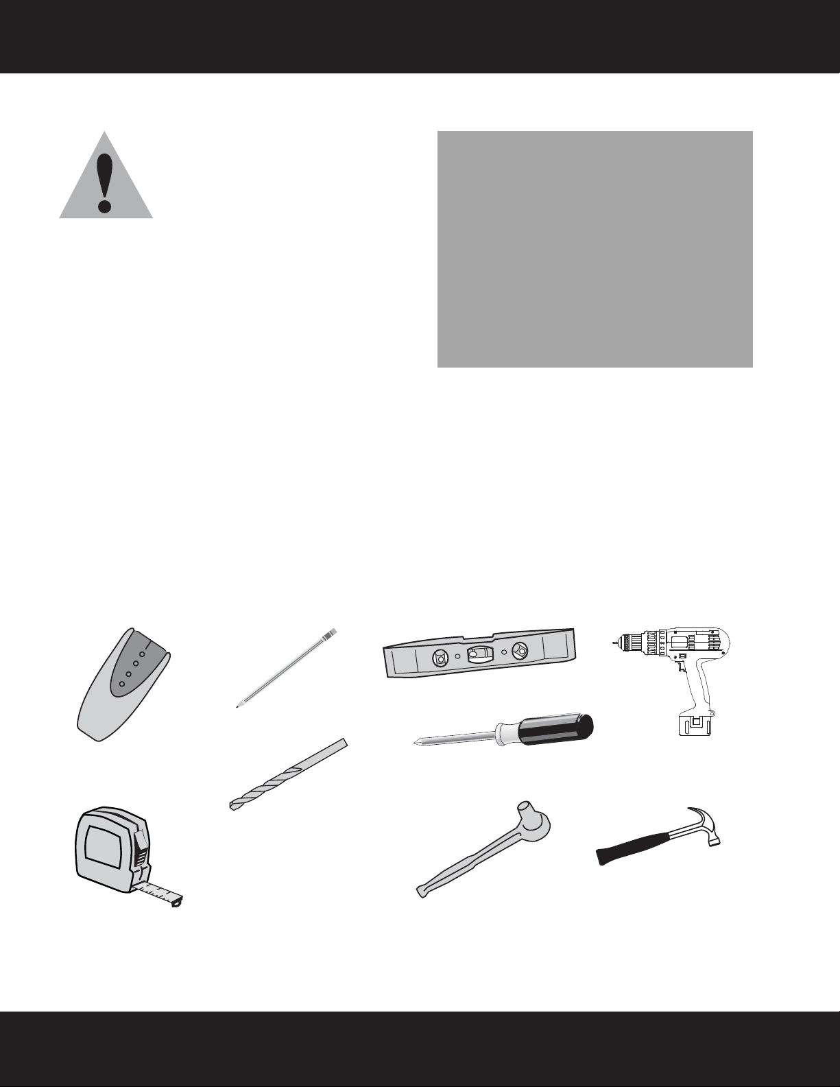
Edge-to-edge
stud finder
Pencil
Level
Phillips screwdriver
Socket wrench with
1/2" (13 mm) socket or
adjustable wrench
Measuring tape
Drill
7/32" (5.5 mm) wood drill
bit for wood stud wall
OR
3/8" (9.5 mm) masonry
drill bit (concrete only)
Hammer
Safety information and specifications
IMPORTANT SAFETY INSTRUCTIONS SAVE THESE INSTRUCTIONS
CAUTION: Do not use this product for
any purpose not explicitly specified by
Rocketfish.
Improper installation may cause
property damage or personal injury. If
you do not understand these directions, or have doubts
about the safety of the installation, contact Customer
Service or call a qualified contractor. Rocketfish is not
responsible for damage or injury caused by incorrect
installation or use.
The included hardware is designed for use on vertical walls
constructed of wood studs or solid concrete. A wood stud
wall is defined as consisting of a minimum of 2x4 wooden
studs (2” wide by 4” deep) with a maximum of 5/8”
drywall. The included hardware is not designed for use with metal studs or cinderblock walls. If you’re uncertain
about the construction of your wall, then please consult a qualified contractor or installer for assistance. For a
safe installation, the wall you are mounting to must support 4 times the weight of the total load. If not, then the
surface must be reinforced to meet this standard. The installer is responsible for verifying that the wall structure
and hardware used in any installation method will safely support the total load.
The weight of your TV must not exceed 20 lbs. (9.1 kg). Rocketfish recommends that the wall be capable of
supporting five times the weight of your TV and wall mount combined, or approximately 125 lbs. (57 kg).
This product contains small items that could be a choking hazard if swallowed. Keep these items away from
young children!
Tools needed
You will need the following tools to assemble your new TV wall mount:
2
Need help? Call 1-800-620-2790 (U.S. and Canada) or 01-800-926-3010 (Mexico)
Page 3
RF-TVMP20 TV Wall Mount
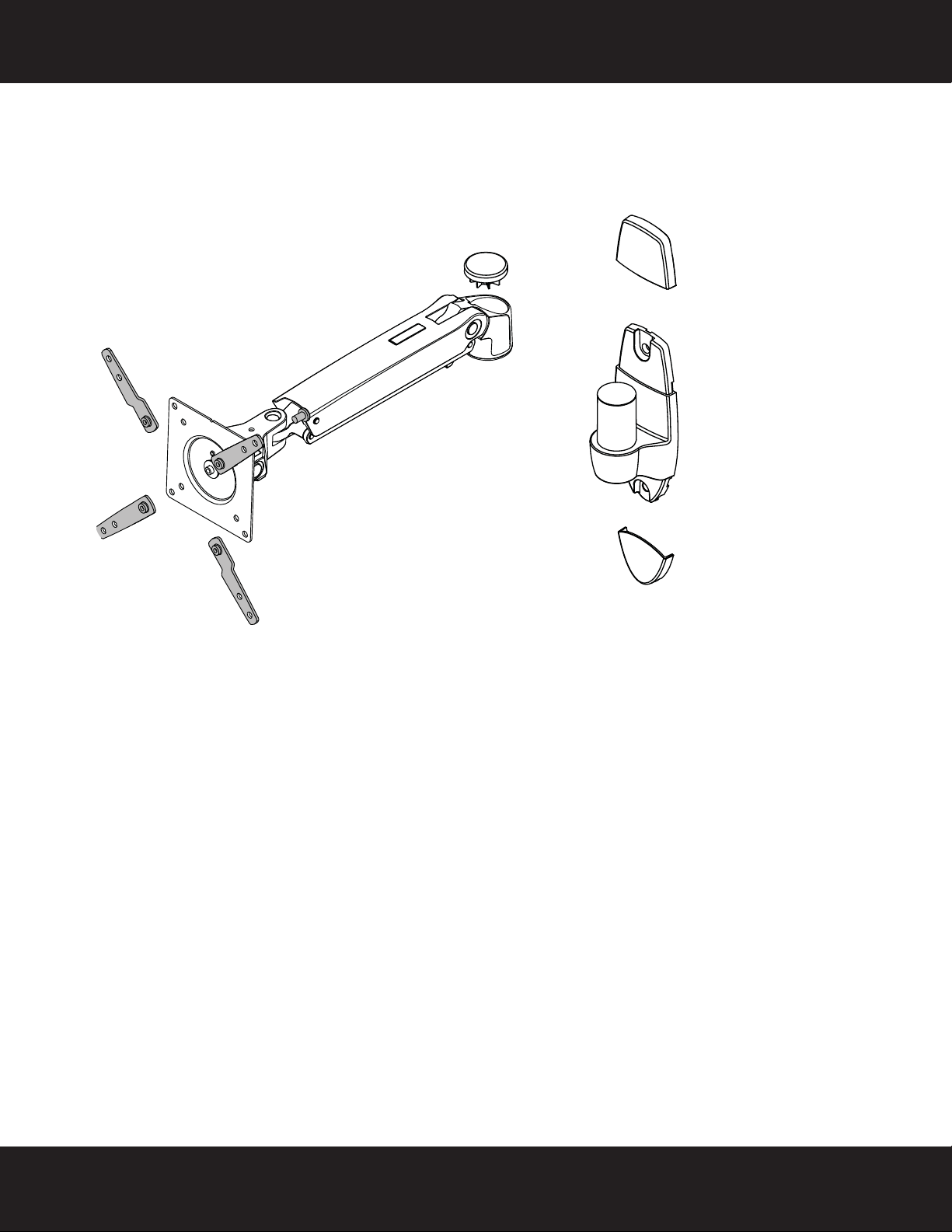
C Adapter (4)
B Arm assembly (1)
A Wall plate (1)
D Top cover (1)
E Bottom cover (1)
F Threaded cap (1)
Package contents: parts
Make sure that you have all the parts necessary to assemble your new TV wall mount:
Need help? Call 1-800-620-2790 (U.S. and Canada) or 01-800-926-3010 (Mexico)
3
Page 4
RF-TVMP20 TV Wall Mount
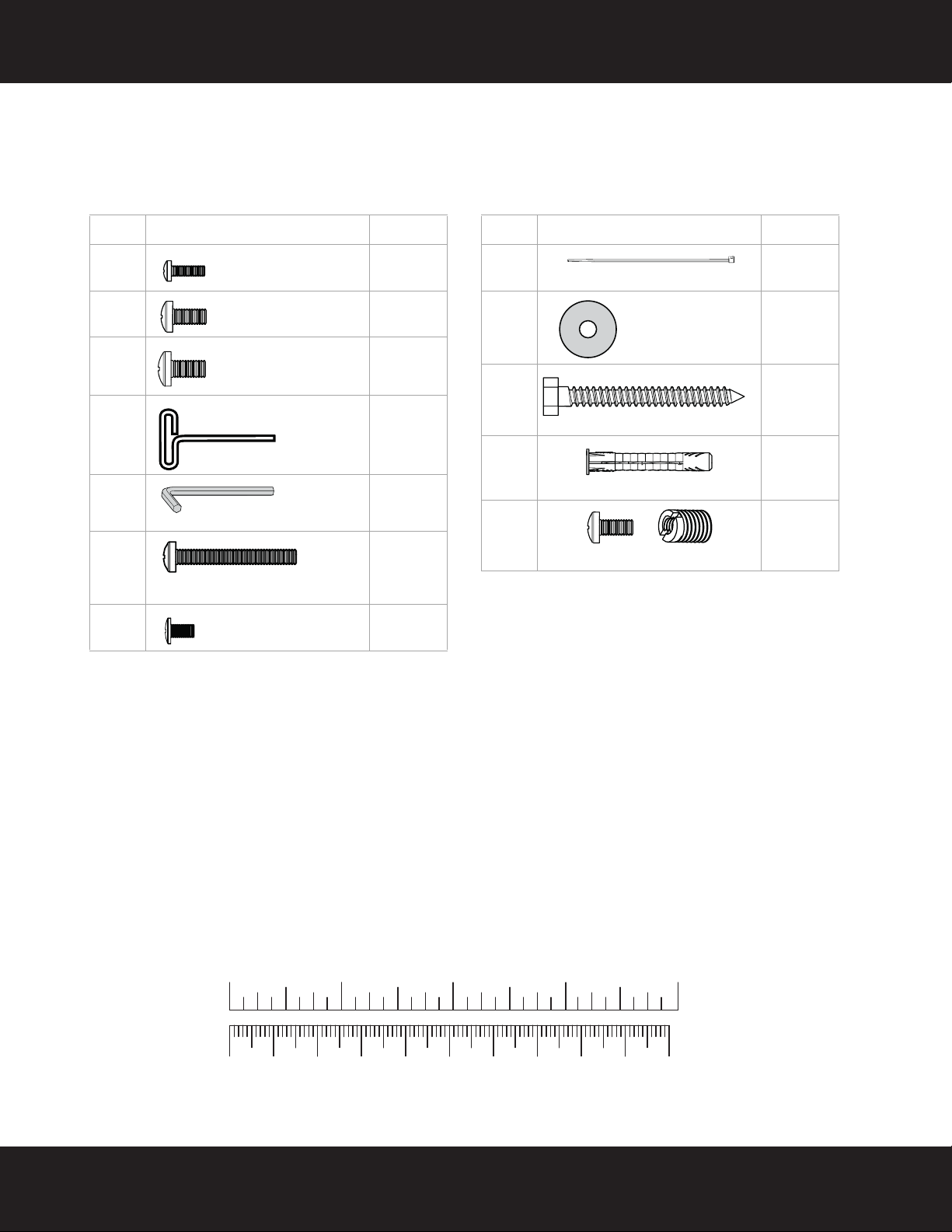
Label Hardware Qty.
M-A 4
M-B 4
M-C 4
P-A 1
P-B 1
P-C 1
P-D 4
M4 × 12 mm screw
M5 × 12 mm screw
M6 × 12 mm screw
4 mm Allen wrench
2.5 mm Allen wrench
M6 x 60 mm screw
M5 × 7 mm screw
Label Hardware Qty.
P-E 2
P-F 1
W-A 2
W-B 2
M8M5
KIT
4
Cable tie
Washer
5/16" × 2 3/4" lag bolt
Concrete anchor
Adapter kit
Package contents: hardware
Make sure that you have all the hardware necessary to assemble your new TV wall mount:
TV Hardware Bag
4
Need help? Call 1-800-620-2790 (U.S. and Canada) or 01-800-926-3010 (Mexico)
1234in
10 20 30 40 50 60 70 80 90 1 00mm
Page 5
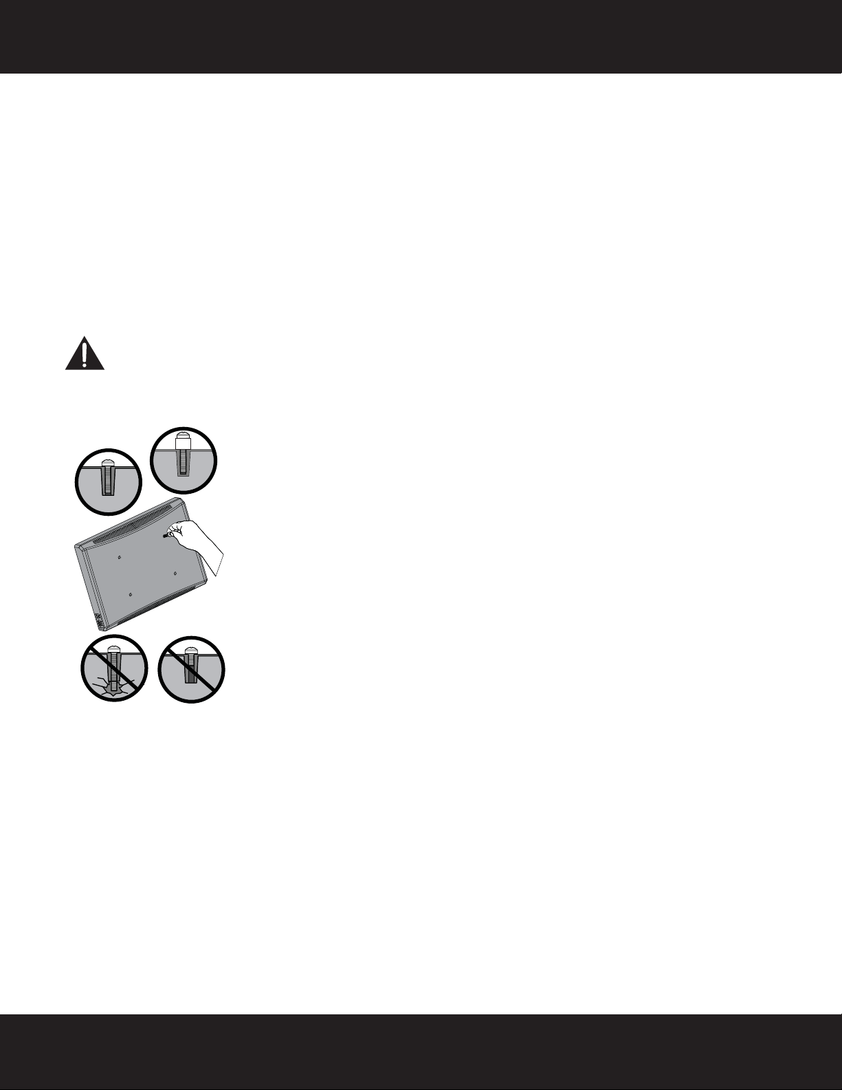
RF-TVMP20 TV Wall Mount
Screw is
too long
Screw fits
correctly
Screw is
too short
Installation instructions
STEP 1- Select screws
1 Select the screws for your TV. A limited number of TVs come with mounting hardware included. (If there are
screws that came with the TV, they are usually in the holes on the back of the TV.) If you don't know the
correct diameter of the mounting screws your TV requires, test various sizes by hand threading the screws.
Select one of the following types of screws:
M4 × 12 mm screws (M-A)
M5 × 12 mm screws (M-B)
M6 × 12 mm screws (M-C)
NOTE: For Samsung TVs with size M8 mounting holes, use the hardware included in the Adapter Kit. Follow the
instructions printed on the Adapter Kit bag to install the hardware.
CAUTION:
threads to secure the brackets to your TV. If you encounter resistance, stop immediately and contact
customer service. Using hardware that is too long may damage your TV. However, using a screw that is
too short may cause your TV to fall from the mount.
To avoid potential personal injuries and property damage, make sure that there are adequate
2 Remove the screws.
Need help? Call 1-800-620-2790 (U.S. and Canada) or 01-800-926-3010 (Mexico)
5
Page 6

RF-TVMP20 TV Wall Mount
200mm (7-7/8”)
200mm (7-7/8”)
100mm (3-15/16”)
200mm (7-7/8”)
75 x 75mm
100 x 100 mm
100 x 200 mm
200 x 200 mm
200 x 100 mm
STEP 2 - Determining your mounting configuration
1 Carefully place your TV screen face down on a cushioned, clean surface to protect the screen from damage
and scratches.
2 If your TV has a table top stand attached, remove the stand. See the documentation that came with your TV
for instructions.
3 Temporarily hold the flat surface of the arm assembly (B) against the back of your TV.
4 Identify the type of mounting configuration by determining if your arm assembly (B) lines up with the screw
holes on the back of your TV or if you will need to install the adapters (C).
5 Remove the arm assembly.
100mm (3-15/16”)
75mm (2-15/16”)
100mm (3-15/16”)
75mm (2-15/16”)
100mm (3-15/16”)
200mm (7-7/8”)
For 75 x 75mm or 100 x 100 mm mounting configurations, go to "STEP 3: Option 1- Attaching the arm assembly
without the adapters" on page 7.
-ORFor a 100 x 200 mm, 200 x 200 mm, or 200 x 100 mm configuration, go to "STEP 3: Option 2 - Attaching the
adapters to the arm assembly" on page 8.
6
Need help? Call 1-800-620-2790 (U.S. and Canada) or 01-800-926-3010 (Mexico)
Page 7

RF-TVMP20 TV Wall Mount
75 x 75mm
100 x 100mm
100mm (3-15/16”)
75mm (2-15/16”)
100mm (3-15/16”)
75mm (2-15/16”)
OR
M-A
B
OR
M-B M-C
TV
M-A (4)
M-B (4)
Phillips screwdriver
OR
OR
Screws
M-C (4)
Level
B Arm assembly
STEP 3: Option 1- Attaching the arm assembly without the adapters
1 Align the arm assembly (B) with the screw holes on the back of the TV.
2 Install screws (M-A, M-B, or M-C) securely into the four holes in the back of the TV. Do not over-tighten.
Note: The arm assembly (B) should be level on the back of the TV. Proceed to Step 4 Determine wall mount location.
You’ll need
Need help? Call 1-800-620-2790 (U.S. and Canada) or 01-800-926-3010 (Mexico)
7
Page 8

RF-TVMP20 TV Wall Mount
100 x 200 mm
200 x 200 mm
200 x 100 mm
P-D (4)
Phillips screwdriver
C Adapters (4)
B Arm assembly
STEP 3: Option 2 - Attaching the adapters to the arm assembly
1 Install the four adapters (C) onto the arm assembly (B) using four M5 x 7mm screws (P-D). Do not
over-tighten.
2 Adjust the adapters (C) to fit your TV configuration, determined in Step 2.
B
P-D
You’ll need
C
8
Need help? Call 1-800-620-2790 (U.S. and Canada) or 01-800-926-3010 (Mexico)
Page 9

RF-TVMP20 TV Wall Mount
Phillips screwdriver
Level
C Adapters (4)
B Arm assembly
M-A (4)
M-B (4)
OR
OR
Screws
M-C (4)
STEP 3: Option 2 - Attaching the arm assembly with adapters
3 Align the adapters (C) with the screw holes on the back of your TV.
4 Install screws determined in Step 1 (M-A, M-B, or M-C) securely into the four holes in the back of the TV. Do
not over-tighten.
5 Proceed to Step 4 Determine wall mount location.
Note: The arm assembly (B) should be level on the back of the TV.
C
You’ll need
TV
B
M-A
M-B M-C
OR
OR
Need help? Call 1-800-620-2790 (U.S. and Canada) or 01-800-926-3010 (Mexico)
9
Page 10

RF-TVMP20 TV Wall Mount
a
b
Measuring tape
Pencil
STEP 4 - Determine wall-mount location
Note:
• For more detailed information on determining where to drill your holes, visit our online height-finder at:
http://mf1.bestbuy.selectionassistant.com/index.php/heightfinder
• Your TV should be high enough so your eyes are level with the middle of the screen. Normally, 40 to 60 inches
from the ground.
When your television is in a position closest to the wall and the arm assembly is horizontal, the center of your
television will be 13" to the left or right of the center of the wall plate (A). Before you drill holes in the wall:
1 Measure the distance from the bottom of your TV to the middle (half of the height of the TV). This is
measurement a.
2 Measure the distance from the floor to where you want the bottom of the TV to be positioned on the wall
when the arm assembly is horizontal. Keep in mind that this TV mount allows for 13" of travel in all directions
from the center of the wall plate. Your TV should be mounted in a position that will not cause it to come in
contact with furniture, or items placed on top of furniture (like a Blu-ray player or cable box). This is
measurement b.
3 Add a + b. This measurement is the height where you want the center of your TV to be.
4 Measure 13" to the left OR right of the a + b measurement position. This will be the desired position for the
center of the wall plate. This is measurement c.
5 Use a pencil to mark this spot on the wall.
13” 13”
c
You’ll need
c
a
b
10
Need help? Call 1-800-620-2790 (U.S. and Canada) or 01-800-926-3010 (Mexico)
Page 11

RF-TVMP20 TV Wall Mount
Center pencil mark made in
Step 1.
2-3/4 in.
(70 mm)
Edge-to edge
stud finder
W-A (2)
Pencil
Drill
7/32" wood
drill bit
1/2" socket
wrench
Level
A Wall
plate
STEP 5 - Option 1: Installing on a wood stud wall
Note: Any wallboard or material covering the wall must not exceed 5/8" (16 mm).
1 Locate the stud. Verify the center of the stud with an edge-to-edge stud finder.
2 Align the wall plate (A) at the height you determined in the previous step and make sure that it is level. Use a
pencil to mark the lag bolt hole locations (2) on the stud centers. Remove the wall plate.
3 Drill pilot holes to a depth of 2-3/4 in. (70 mm) using a 7/32 in. (5.5 mm) diameter drill bit.
4 Align the wall plate (A) with the pilot holes, insert the lag bolts (W-A) through the holes in the wall plate,
then tighten the lag bolts only until they are firm against the wall plate.
CAUTION: Avoid potential injuries or property damage!
DO NOT over-tighten the lag bolts (W-A).
A
W-A
You’ll need
Need help? Call 1-800-620-2790 (U.S. and Canada) or 01-800-926-3010 (Mexico)
11
Page 12

RF-TVMP20 TV Wall Mount
2-3/4 in.
(70 mm)
Edge-to edge
stud finder
W-A (2)
Pencil
Drill
3/8" masonry
drill bit
1/2" socket
wrench
Level
W-B (2)
Hammer
A Wall
plate
STEP 5 - Option 2: Installing on a solid concrete wall
1 Align the wall plate (A) at the height you determined in the previous step and make sure that it is level. Use a
pencil to mark the lag bolt hole locations (2). Remove the wall plate.
2 Drill pilot holes to a depth of 2-3/4 in. (7 mm) using a 3/8 in. (10 mm) diameter masonry drill bit.
3 Insert the concrete wall anchors (W-B) into the pilot holes and use a hammer to make sure the anchors are
flush with the concrete surface.
4 Align the wall plate (A) with the anchors, insert the lag bolts (W-A) through the holes in the wall plate, then
tighten the lag bolts only until they are firm against the wall plate.
CAUTION: Avoid potential injuries or property damage!
DO NOT over-tighten the lag bolts (W-A).
You’l l n e ed
W-B
A
W-A
12
Need help? Call 1-800-620-2790 (U.S. and Canada) or 01-800-926-3010 (Mexico)
Page 13

RF-TVMP20 TV Wall Mount
HEAVY! You will need
assistance with this step.
Phillips screwdriver
Level
F Threaded Cap
P-C (1)
P-F (1)
STEP 6 - Attach your TV to the wall plate
1 Holding the TV level, with the screen parallel to the wall. Place the arm assembly (B) over the wall plate (A) as
shown below.
2 Place the theaded cap (F) over the wall plate (A) and install the washer (P-F) and M6 x 60 mm screw (P-C).
You’ll need
Need help? Call 1-800-620-2790 (U.S. and Canada) or 01-800-926-3010 (Mexico)
13
Page 14

RF-TVMP20 TV Wall Mount
D
E
P-E
D & E Wall plate covers
P-E Cable ties (2)
STEP 7 - Installing the covers and cable ties
1 Install the top and bottom covers (D & E) onto the wall plate (A).
2 Connect the cable to your TV, then secure the cable to the underside of the arm assembly (B) with two cable
ties (P-E).
14
Need help? Call 1-800-620-2790 (U.S. and Canada) or 01-800-926-3010 (Mexico)
You’ l l n e e d
Page 15

RF-TVMP20 TV Wall Mount
Increase
If TV weight
exceeds product’s
factory setting, it
won’t stay up
when raised. To
prevent TV from
sagging
downward,
increase tension
setting.
Adjusting the factory-set tension
Decrease
If TV weight is
lower than
product’s factory
setting, it won’t
stay down when
lowered. To
prevent TV from
drifting upward,
decrease tension
setting.
P-A 4 mm Allen wrench
P-B 2.5 mm Allen wrench
STEP 8 - Adjusting the vertical position, the tilt, and the horizontal position
Important! You will need to adjust this product after installation is complete.
Make sure all your equipment is properly installed on the product before adjusting. This product should move
smoothly and easily through the full range of motion and stay where you set it. If movements are too easy or diffcult or
if product does not stay in desired position, follow the adjustment instructions to create smooth and easy movements.
NOTE: Depending on your product and the type of adjustment, it may take many turns to notice a difference.
Any time equipment is added or removed from this product, resulting in a change in the weight of the mounted load,
you should repeat these adjustment steps to ensure safe and optimum operation.
1 To increase or decrease the lift tension setting, use the 4mm Allen wrench (P-A).
2 To increase or decrease the tilt tension setting, use the 4mm Allen wrench (P-A).
3 Using the 2.5mm Allen wrench (P-B) adjust the tension of the horizontal movement. If this product moves
too easily from side-to-side, increase the tension (+). If the product is too difficult to move from side-to-side,
decrease the tension (-).
2
1
P-A
3
For customer service, call: 1-800-620-2790 (U.S. and Canada) or 01-800-926-3010
(Mexico)
Need help? Call 1-800-620-2790 (U.S. and Canada) or 01-800-926-3010 (Mexico)
You’ll need
15
Page 16

www.rocketfishproducts.com 1-800-620-2790 (U.S. and Canada) or 01-800-926-3010 (Mexico)
Distributed by Best Buy Purchasing, LLC
7601 Penn Avenue South, Richfield, MN 55423-3645 USA
© 2013 BBY Solutions, Inc.
All rights reserved. ROCKETFISH is a trademark of BBY Solutions, Inc.
All other products and brand names are trademarks of their respective owners.
Part number: 888-61-044-W-01
V2 ENGLISH 13-0707
 Loading...