

Page 1
RF-TVML70
TV Wall Mount
For wood-stud and concrete
wall installations
Before using your new product, please read these instructions to prevent any damage.
Safety information and specifications .................................2
Tools needed.................................................................................2
Package contents: parts ............................................................3
Package contents: hardware...................................................4
Installation instructions.............................................................5
Assembly Guide
Page 2
RF-TVML70 TV Wall Mount
Maximum TV weight: 70 lbs. (31.8 kg)
Minimum TV weight: 45 lbs. (20.4 kg)
Maximum TV Screen size: 70 in. diagonal
Overall dimensions (W × H ):
10.5 x 23.8 in. (26.7 x 60.3 cm)
Wall-mount weight: 28 lbs. (12.7 kg)
We’re here for you
www.rocketfishproducts.com
For customer service, call:
800-620-2790 (U.S./Canada markets)
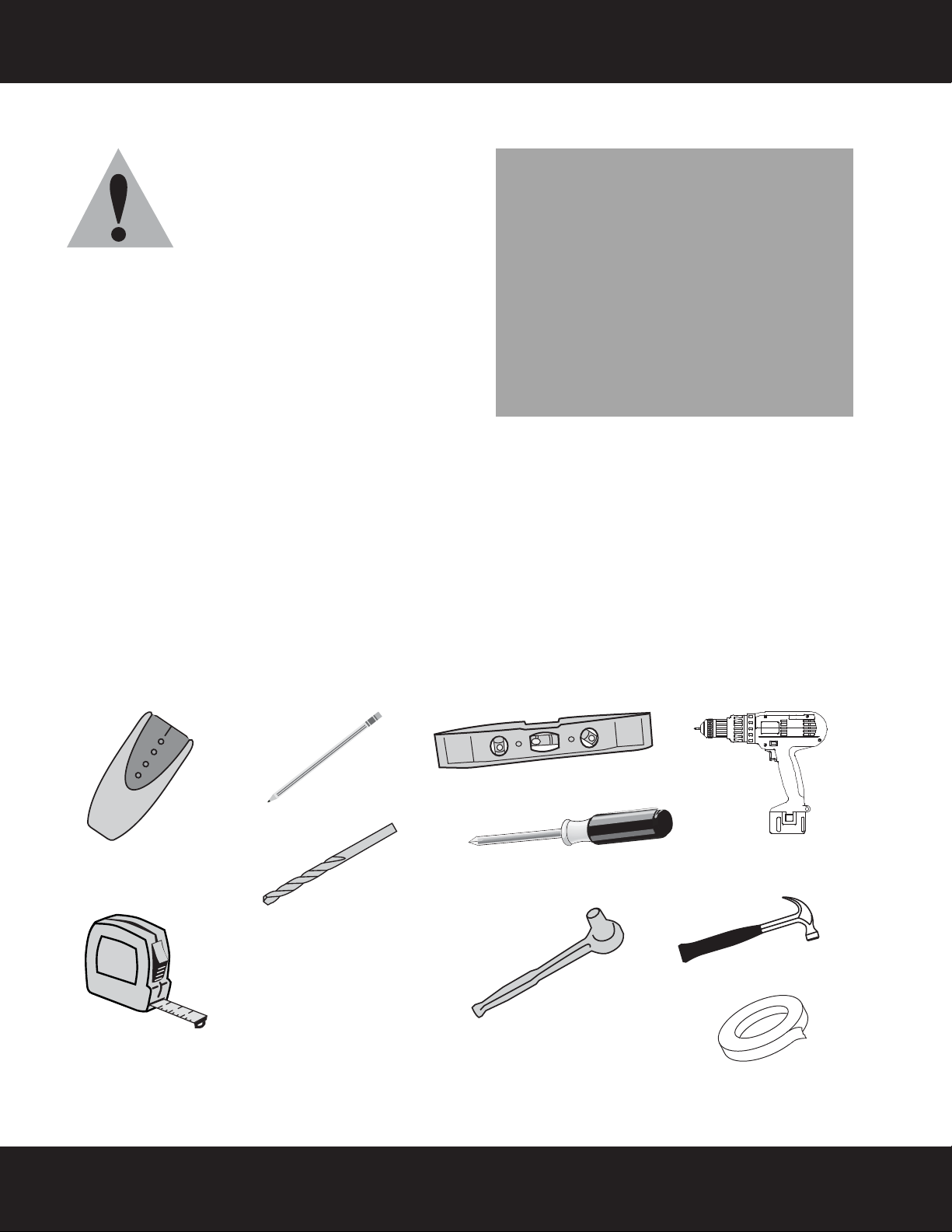
Edge-to-edge
stud finder
Pencil
Level
Phillips screwdriver
Socket wrench with
1/2" (13 mm) socket or
adjustable wrench
Measuring tape
Drill
7/32" (5.5 mm) and 1/2”
(13 mm) wood drill bit for
for wood stud wall
OR
3/8" (9.5 mm) masonry
drill bit (concrete only)
Hammer
Tape
Safety information and specifications
IMPORTANT SAFETY INSTRUCTIONS SAVE THESE INSTRUCTIONS
CAUTION: Do not use this product for
any purpose not explicitly specified by
Rocketfish.
Improper installation may cause
property damage or personal injury. If
you do not understand these directions, or have doubts
about the safety of the installation, contact Customer
Service or call a qualified contractor. Rocketfish is not
responsible for damage or injury caused by incorrect
installation or use.
The included hardware is designed for use on vertical walls
constructed of wood studs or solid concrete. A wood stud
wall is defined as consisting of a minimum of 2x4 wooden
studs (2” wide by 4” deep) with a maximum of 5/8”
drywall. The included hardware is not designed for use with metal studs or cinderblock walls. If you’re uncertain
about the construction of your wall, then please consult a qualified contractor or installer for assistance. For a
safe installation, the wall you are mounting to must support 4 times the weight of the total load. If not, then the
surface must be reinforced to meet this standard. The installer is responsible for verifying that the wall structure
and hardware used in any installation method will safely support the total load.
The weight of your TV must not exceed 70 lbs. (31.8 kg). Rocketfish recommends that the wall be capable of
supporting five times the weight of your TV and wall mount combined, or approximately 350 lbs. (159 kg).
This product contains small items that could be a choking hazard if swallowed. Keep these items away from
young children!
Tools needed
You will need the following tools to assemble your new TV wall mount:
2
Need help? Call 800-620-2790
Page 3
RF-TVML70 TV Wall Mount
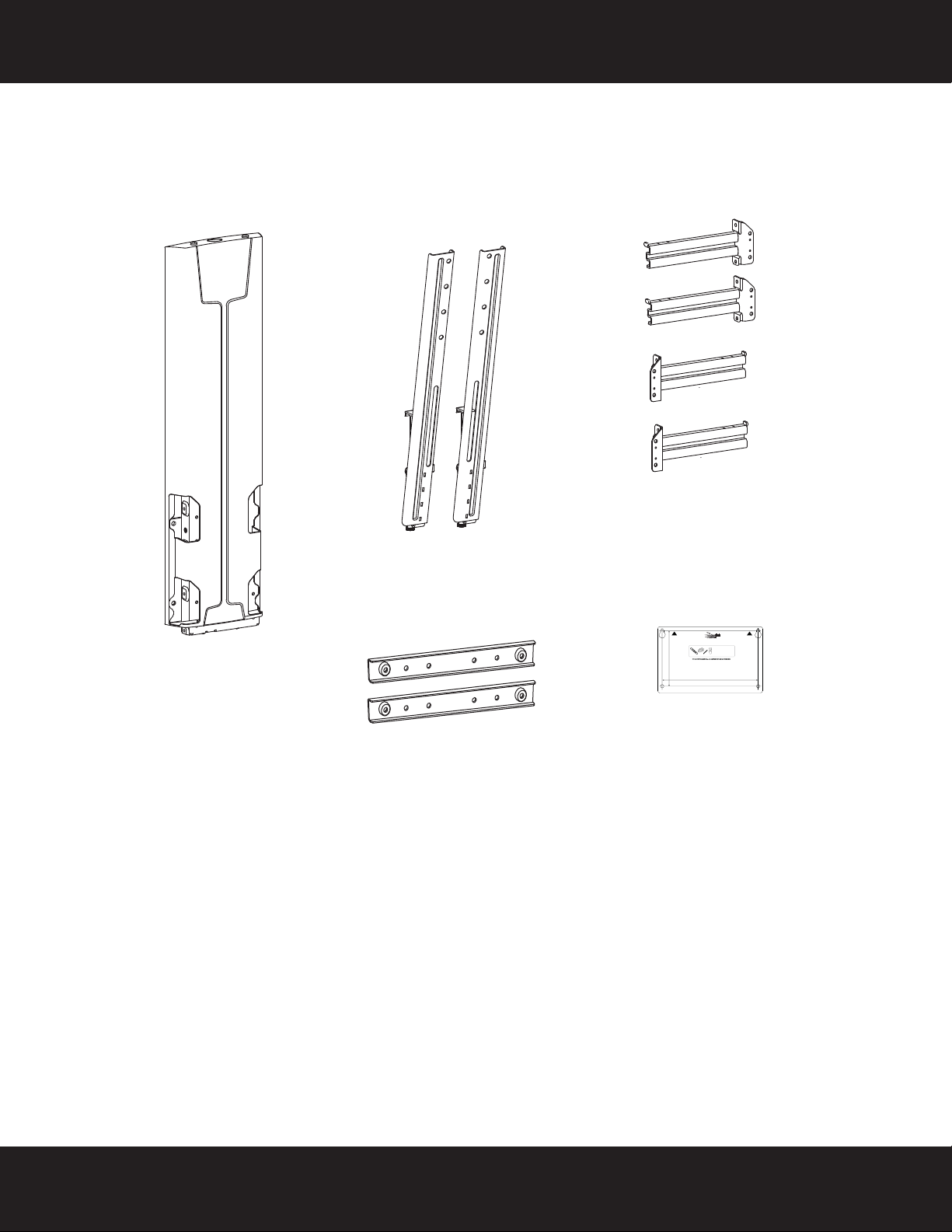
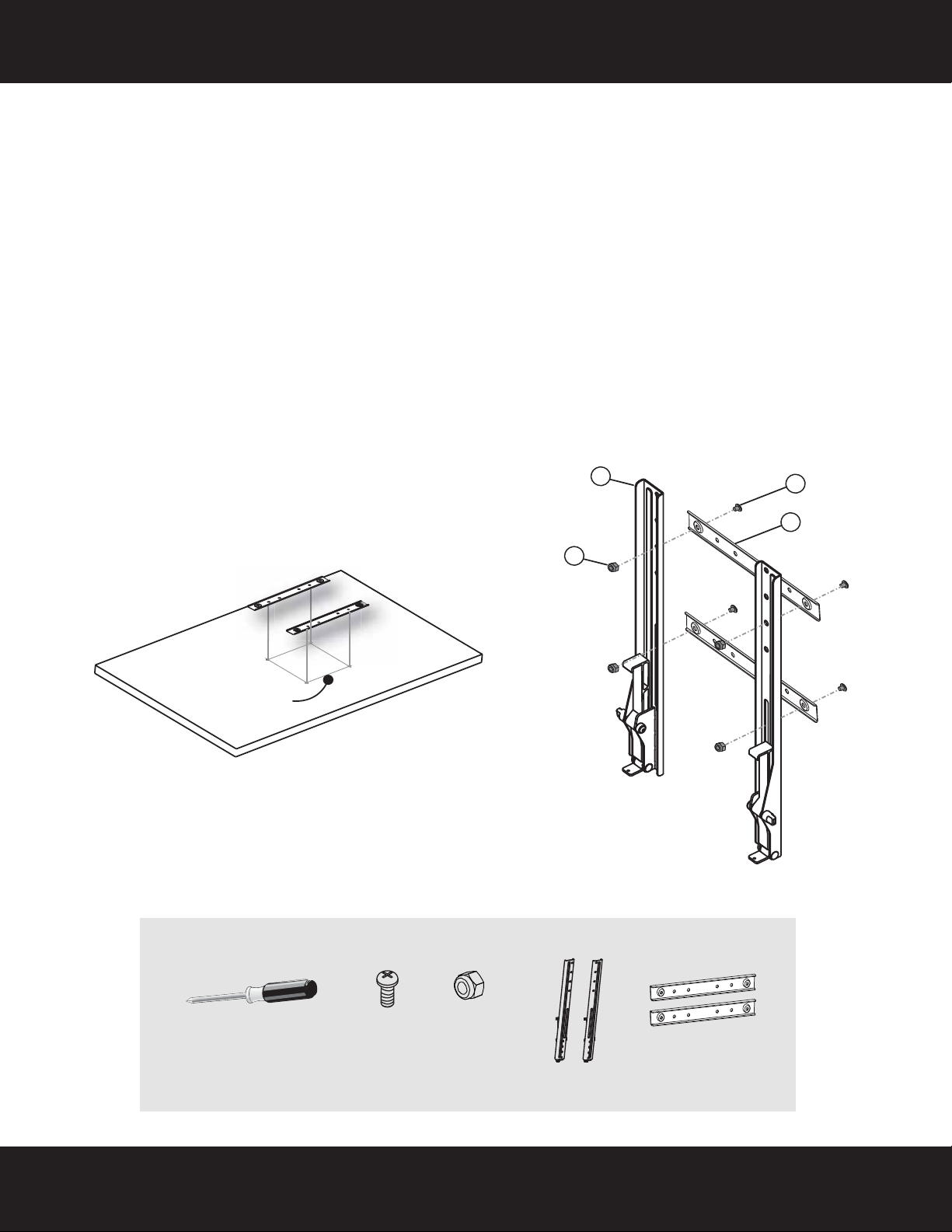
A Lift assembly (1)
C Horizontal rails (4)
B Vertical rails (2)
D Template (1)
E VESA adapters (2)
Package contents: parts
Make sure that you have all the parts necessary to assemble your new TV wall mount:
Top
Dessus
Parte superior
5.47" (139.0 mm)
RF-TVML70 Template • Gabarit • Plantilla
Tools Needed
Outils nécessaires
Herramientas requeridas
Note
Remarque : Pour une construction à ossature de bois, localiser d'abord les montants
en bois, à l'aide d'un détecteur de montants.
Nota: para la instalación en construcciones de armazón de madera, primero debe
localizar las vigas de madera con un localizador de vigas.
9.43" (239.6 mm)
Top
Dessus
Parte superior
Need help? Call 800-620-2790
3
Page 4
RF-TVML70 TV Wall Mount
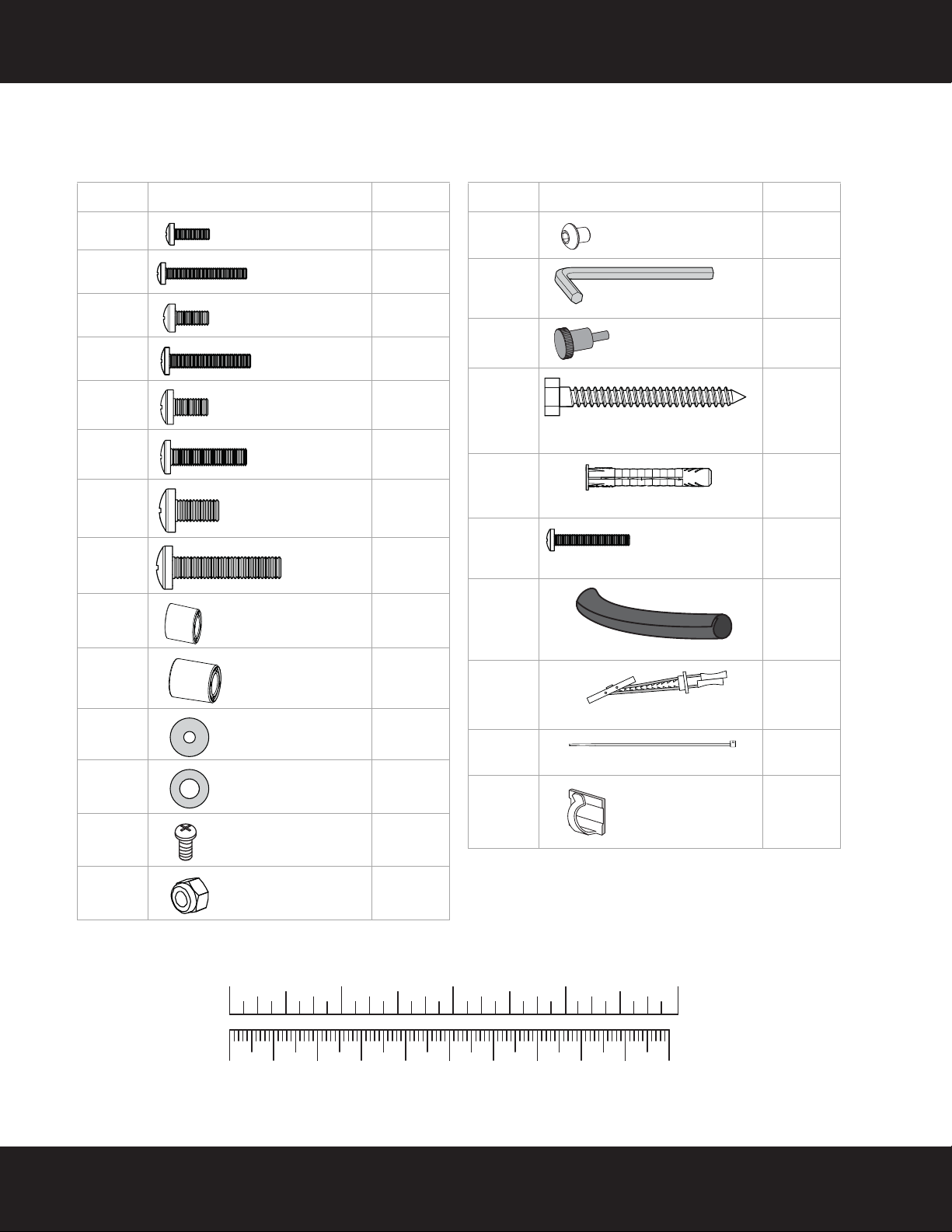
Label Hardware Qty.
M-A 4
M-B 4
M-C 4
M-D 4
M-E 4
M-F 4
M-G 4
M-H 4
M-I 4
M-J 4
M-K 4
M-L 4
M-M 4
M-N 4
M4 × 15 mm screw
M4 × 30 mm
screw
M5 × 15 mm screw
M5 × 30 mm
screw
M6 × 15 mm screw
M6 × 30 mm
screw
M8 × 15 mm
screw
M8 × 30 mm
screw
M6/M8 5 mm spacer
M6/M8 10 mm
spacer
M4/M5 Washer
M6/M8 Washer
Pan head screw
M8 x 15 mm
M8 Nylock nut
Label Hardware Qty.
P-A 16
P-B 1
P-C 2
W-A 4
W-B 4
W-C 2
E1
F2
G4
H2
Button head screw
4 mm Allen wrench
Knob screw M4 x0.7”
5/16" × 2 3/4" (8 mm x 80 mm)
lag bolt
Wall anchor
1/4-20 x 1-1/2”
Hex Socket Screw
Cable tubing
Snap toggle
Cable tie
Cable clip
Package contents: hardware
Make sure that you have all the hardware necessary to assemble your new TV wall mount:
4
10 20 30 40 50 60 70 80 90 1 00mm
1234in
Need help? Call 800-620-2790
Page 5
RF-TVML70 TV Wall Mount
7.9” (200 mm)
M-N Nylock
nuts (4)
Phillips screwdriver
M-M Pan head
screws (4)
(B) Vertical
rails (2)
(E) VESA
adapters (2)
Installation instructions
STEP 1 - Determine whether you need the optional VESA adapters
1 Carefully place your TV screen face-down on a cushioned, clean surface to protect the screen from damages
and scratches.
2 If your TV has a table-top stand attached, remove the stand. See the documentation that came with your TV
for instructions.
3 Measure the distance between the mounting holes on the back of your TV.
4 If the distance equals 7.9” (200 mm), you will need to attach the VESA adapters (E) before proceeding to
Step 2.
OR
If the distance is greater than 7.9” (200 mm), the VESA adapters (E) are not needed and you can proceed
directly to Step 2.
5 To attach the optional VESA adapters (E), insert the panhead screws (M-M) into the recessed holes of the
VESA adapters (E) and through the vertical rails (B), then insert the nylock nuts (M-N) into the back of the
vertical rail and thread them onto the screws and tighten. Make sure that the flat side of the adapter will be
against the back of the TV when assembled.
M-N
A
M-M
E
You’ll need
Need help? Call 800-620-2790
5
Page 6
RF-TVML70 TV Wall Mount
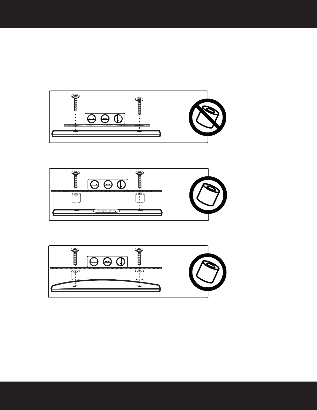
STEP 2 - Determine whether your TV has a flat back or an irregular or obstructed
back
1 Temporarily lay the vertical rails (B) on the back of your TV.
2 Align the screw holes in the vertical rails or VESA adapters with the mounting screw holes on your TV.
3 Identify which type of back your TV may have:
• Flat back: The vertical rails lay flush against the back of your TV and do not block any jacks. You do
not need spacers when assembling the wall mount.
• Obstructed back: A vertical rail blocks any of the jacks on the back of your TV. You will need spacers
when assembling the wall mount.
• Irregularly-shaped back: There is a gap between a vertical rail and some part of the back of your TV.
You will need spacers when assembling the wall mount.
4 Remove the vertical rails.
6
Need help? Call 800-620-2790
Page 7

RF-TVML70 TV Wall Mount
Screw is
too long
Screw fits
correctly
Screw is
too short
STEP 3 - Select screws, washers, and spacers
1 Select the screws for your TV. A limited number of TVs come with mounting hardware included. (If there are
screws that came with the TV, they are usually in the holes on the back of the TV.) If you don't know the
correct length and diameter of the mounting screws your TV requires, test various sizes by hand threading
the screws.
Select one of the following types of screws:
M4 × 15 mm screws (M-A)M6×15mm screws (M-E)
M4 × 30 mm screws (M-B)M6×30mm screws (M-F)
M5 × 15 mm screws (M-C)M8×15mm screws (M-G)
M5 × 30 mm screws (M-D)M8×30mm screws (M-H)
Select one of the following types of washers:
M4/M5 washers (M-K) M6/M8 washers (M-L)
For an irregular or obstructed TV back, use one of the following spacers:
M6/M8 5 mm spacers (M-I) M6/M8 10 mm spacers (M-J)
CAUTION: To avoid potential personal injuries and property damage, make sure that there are adequate
threads to secure the brackets to your TV. If you encounter resistance, stop immediately and contact
customer service. Use the shortest screw available to accommodate your TV. Using hardware that is too
long may damage your TV. However, using a screw that is too short may cause your TV to fall from the
mount.
2 Remove the screws.
Need help? Call 800-620-2790
7
Page 8

RF-TVML70 TV Wall Mount
or
or
or
or
or
or
or
or
NOTE: M4 screws (parts M-A or M-B)
should not be used for hole patterns
greater than 200 mm x 200 mm.
M-A (4)
M-B (4)
Phillips screwdriver
or
or
M-C (4)
Level
(B) Vertical
rails (2)
or
M-D (4)
or
M-E (4)
or
M-F (4)
M-G (4)
or
M-H (4)
or
M-K (4)
M-L (4)
or
M-I (4)
M-J (4)
STEP 4: Option 1- Attaching the vertical rails to the TV
1 Align the vertical rails (B) with the screw holes on the back of the TV.
2 Install the screws you identified in Step 2 (M-A, M-B, M-C, M-D, M-E, M-F, M-G, or M-H) securely into the
four holes in the back of the TV, using washers (M-K or M-L) and spacers (M-I or M-J) as necessary. Do not
over-tighten.
Note: The tops of the vertical rails (B) should be level on the back of the TV.
B
M-A M-B M-C
You’ll need
M-K
M-I M-J
M-L
M-D
M-E M-F M-G M-H
8
Need help? Call 800-620-2790
Page 9

RF-TVML70 TV Wall Mount
B
M-A M-B M-C
M-I M-J
M-D
M-E M-F M-G M-H
M-K
M-L
E
or
or
or
or
or
or or
or
NOTE: M4 screws (parts M-A or M-B)
should not be used for hole patterns
greater than 200 mm x 200 mm.
M-A (4)
M-B (4)
Phillips screwdriver
or
or
M-C (4)
Level
(B) Vertical
rails (2)
or
M-D (4)
or
M-E (4)
or
M-F (4)
M-G (4)
or
M-H (4)
or
M-K (4)
M-L (4)
or
M-I (4)
M-J (4)
E VESA adapters (2)
STEP 4: Option 2- Attaching the vertical rails and adapters to the TV
1 Align the vertical rails (B) with the VESA adapters (E) with the screw holes on the back of the TV.
2 Install the screws you identified in Step 2 (M-A, M-B, M-C, M-D, M-E, M-F, M-G, or M-H) securely into the
four holes in the back of the TV, using washers (M-K or M-L) and spacers (M-I or M-J) as necessary. Do not
over-tighten.
Note: The tops of the vertical rails (B) should be level on the back of the TV.
You’ l l n ee d
Need help? Call 800-620-2790
9
Page 10

RF-TVML70 TV Wall Mount
CAUTION: Risk of electrical
shock. To ensure safe use of
this product, install power
outlets or supplies outside of
the horizontal rails. Do not
route electrical cords within
the path of the horizontal
rails. Be aware of pinch
points when routing cables.
Failure to heed this caution
may result in equipment
damage or personal injury.
Refer to “STEP 9 - Installing
the cable wrap and cable
ties” on page 16, for
information on how to
appropriately route your
power, HDMI, and AV cables.
Measuring tape
Pencil
STEP 5 - Determine wall-mount location
Notes:
• For more detailed information on determining where to drill your holes, visit our online height-finder at:
http://mf1.bestbuy.selectionassistant.com/index.php/heightfinder
• Your TV should be high enough so your eyes are level with the middle of the screen. Normally, 40 to 60 inches
from the ground.
When your TV is initially mounted on the wall, it will normally be mounted in its highest position. You will only
be able to lower your TV (approximately 16 inches) from this position.
1 Measure the distance from the bottom of your TV to the middle (half of the height of the TV). This is
measurement a.
2 Measure the distance from the floor to where you want the bottom of the TV to be positioned on the wall
(we recommend approximately 42” from the floor for comfortable sit-stand viewing). Keep in mind that this
TV mount allows for 16" of travel vertically downward from the initial mounting position. This is
measurement b.
3 Add a + b. This measurement is the height where you want the center of your TV to be.
4 Use a pencil to mark this spot on the wall.
a
b
You’ll need
10
Need help? Call 800-620-2790
Page 11

RF-TVML70 TV Wall Mount
Center pencil mark
made in Step 1.
3.15 in.
(80 mm)
a
c
d
b
Wallboard
STEP 6 - Option 1: Installing on a wood stud wall
Note: Any wallboard or material covering the wall must not exceed 5/8" (16 mm).
1 Locate the stud. Verify the center of the stud with an edge-to-edge stud finder.
2 Align the wall plate template (D) at the height you determined in the previous step, so that it lines up with at
least one stud, make sure that it is level, then tape it to the wall. Use a pencil to mark the lag bolt hole
locations (2) on the stud centers and snap toggle locations (2) on the wallboard. Remove the wall plate
template.
3 Drill pilot holes in the wood stud for the lag bolts (W-A) to a depth of 3.15 in. (80 mm) using a 7/32 in.
(5.5 mm) diameter drill bit, then drill holes for the snap toggles (F) (2) in the wallboard using a 1/2 in.
(13 mm) diameter drill bit.
4 Install the snap toggles (F) into the wallboard (not the stud).
a Fold the metal bar part of the toggle (F) flat, then insert it into the hole drilled in the previous step.
b The metal bar should unfold behind the wall. Gently pull the snap toggle (F) forward until the metal bar
comes in contact with the wall.
c Push the grommet part of the snap toggle (F) along the plastic sliders toward the wall. Gently push the
gromet into the opening to form a rim around the hole.
d With the toggle grommet firmly engaged in the wall, snap off the plastic sliders and remove the remaining
part of the toggle.
5 Attach the lift assembly (A) to the wall using two 1/4-20 x 1-1/2” hex socket screws (W-C) through the snap
toggles (F). Use a 4 mm Allen wrench (P-B) to tighten. Do not over tighten.
6 Insert the two lag bolts (W-A) through the holes in the lift assembly (A), then tighten the lag bolts into the
stud only until they are firm against the lift assembly (A). Do not over tighten.
CAUTION: Avoid potential injuries or property damage!
DO NOT over-tighten the lag bolts (W-A) or screws (W-C).
5 & 6
A
W-A
W-C
Need help? Call 800-620-2790
11
Page 12

STEP 6 - Option 1: (continued)
Edge-to edge
stud finder
W-A (2)
Pencil
Drill
7/32" wood drill bit
and 1/2” drill bit
13 mm socket
wrench
Level
A Lift assembly
D Template
Tape
F Snap toggles (2)
W-C 1/4-20 x 1-1/2”
hex socket screws (2)
P-B 4 mm
Allen wrench
You’l l ne e d
RF-TVML70 TV Wall Mount
Top
Dessus
Parte superior
5.47" (139.0 mm)
RF-TVML70 Template • Gabarit • Plantilla
Tools Needed
Outils nécessaires
Herramientas requeridas
Note
Remarque : Pour une construction à ossature de bois, localiser d'abord les montants
en bois, à l'aide d'un détecteur de montants.
Nota: para la instalación en construcciones de armazón de madera, primero debe
localizar las vigas de madera con un localizador de vigas.
9.43" (239.6 mm)
Top
Dessus
Parte superior
12
Need help? Call 800-620-2790
Page 13

RF-TVML70 TV Wall Mount
3.18 in.
(80 mm)
Edge-to edge
stud finder
W-A (2)
Pencil
Drill
3/8" masonry drill bit
13 mm socket
wrench
Level
W-B (2)
Hammer
D Template
Tape
A Lift assembly
STEP 6 - Option 2: Installing on a solid concrete wall
1 Align the wall plate template (D) at the height you determined in the previous step and make sure that it is
level, then tape it to the wall. Use a pencil to mark the lag bolt hole locations (4). Remove the template.
2 Drill pilot holes to a depth of 3.15 in. (80 mm) using a 3/8 in. (10 mm) diameter masonry drill bit.
3 Insert the concrete wall anchors (W-B) into the pilot holes and use a hammer to make sure that the anchors
are flush with the concrete surface.
4 Align the lift assembly (A) with the anchors, insert the lag bolts (W-A) through the holes in the wall plate,
then tighten the lag bolts only until they are firm against the wall plate.
CAUTION: Avoid potential injuries or property damage!
DO NOT over-tighten the lag bolts (W-A).
D
You’ll need
Top
Dessus
Parte superior
5.47" (139.0 mm)
RF-TVML70 Template • Gabarit • Plantilla
Outils nécessaires
Herramientas requeridas
Note
Remarque : Pour une construction à ossature de bois, localiser d'abord les montants
en bois, à l'aide d'un détecteur de montants.
Nota: para la instalación en construcciones de armazón de madera, primero debe
localizar las vigas de madera con un localizador de vigas.
9.43" (239.6 mm)
W-A
W-B
W-B
A
Top
Dessus
Parte superior
Tools Needed
Need help? Call 800-620-2790
13
Page 14

RF-TVML70 TV Wall Mount
C Horizontal rails (4)
P-B 4 mm Allen wrench
P-A Button head
screw (16)
STEP 7 - Attach the horizontal rails to the lift assembly
1 Using the 4 mm Allen wrench (P-B), install the right and left horizontal rails (C) onto the lift assembly (A)
using four button head screws (P-A) for each horizontal rail.
14
You’ll need
Need help? Call 800-620-2790
Page 15

RF-TVML70 TV Wall Mount
HEAVY! You will need
assistance with this step.
NOTE: This shows the front of the vertical rails.
The back of the rails have hooks that will hang
over the horizontal rails.
P-C (2)
STEP 8 - Attach your TV to the lift assembly
1 Hang the hooks of the vertical rails (B) over the top horizontal rails (C), then lower the bottom tabs of the
vertical rails (B) under the bottom horizontal rail (C).
2 Secure with the knob screws (P-C) through the bottoms of the vertical arms (B).
You’ l l n ee d
Need help? Call 800-620-2790
15
Page 16

RF-TVML70 TV Wall Mount
E Cable tubing
G Cable ties (4)
H Cable clips (2)
STEP 9 - Installing the cable wrap and cable ties
1 Connect the cable to your TV, then secure the cable to the lift assembly (A) with cable ties (G) or cable clips
(H), as necessary.
2 Install the cable tubing (E) on the cables to provide a neater appearance.
16
You’ l l n ee d
Need help? Call 800-620-2790
Page 17

RF-TVML70 TV Wall Mount
Up to 16”
Increase
If TV weight exceeds product’s factory setting, it
won’t stay up when raised. To prevent TV from
sagging downward, increase tension setting.
Adjusting the factory-set tension
Decrease
If TV weight is lower than product’s factory
setting, it won’t stay down when lowered. To
prevent TV from drifting upward, decrease
tension setting.
2
Up to 10°
Socket wrench w/13 mm socket
STEP 10 - Adjusting the vertical motion and tilt
Important! You will need to adjust this product after installation is complete.
Make sure all your equipment is properly installed on the product before adjusting. This product should move
smoothly and easily through the full range of motion and stay where you set it. If movements are too easy or diffcult or
if product does not stay in desired position, follow the adjustment instructions to create smooth and easy movements.
NOTE: Depending on your product and the type of adjustment, it may take many turns to notice a difference.
Any time equipment is added or removed from this product, resulting in a change in the weight of the mounted load,
you should repeat these adjustment steps to ensure safe and optimum operation.
1 To increase or decrease the lift tension setting, use the socket wrench w/13 mm socket.
2 Loosent the tilt adjustment knob, then tilt the TV to the angle you want. Retighten the tilt adjustment knob.
You can adjust the tilt up to 10° forward.
1
You’ l l n ee d
For customer service, call: 800-620-2790 (U.S./Canada markets)
Need help? Call 800-620-2790
17
Page 18

www.rocketfishproducts.com (800) 620-2790
Distributed by Best Buy Purchasing, LLC
7601 Penn Avenue South, Richfield, MN 55423-3645 USA
© 2013 BBY Solutions, Inc.
All rights reserved. ROCKETFISH is a trademark of BBY Solutions, Inc.
All other products and brand names are trademarks of their respective owners.
Part Number: 888-61-046-W-01
V3 ENGLISH 13-0455
 Loading...