

Page 1

URISYS 2400
Operator’s Manual
Version 1.0
Page 2
Revision History
URISYS 2400
Version Revision date
1.0 April 2001
Language Order No.
English
Edition notice URISYS 2400 Operator’s Manual
This manual is for users of the URISYS 2400.
Every effort has been made to ensure that all the information contained in this
manual is correct at the time of printing. However, Roche Diagnostics GmbH
reserves the right to make any changes necessary without notice as part of
ongoing product development.
Any customer modification to the instrument will render the warranty or
service agreement null and void.
Intended use The URISYS 2400 is a fully automated urinalysis system intended for in vitro
qualitative or semi-quantitative determination of urine analytes, including
pH, leukocytes, nitrite, protein, glucose, ketones, urobilinogen, bilirubin, and
erythrocytes.
Copyrights © 2001, Roche Diagnostics GmbH. All rights reserved.
Trademarks The following trademarks are acknowledged:
, URISYS 2400 are registered trademarks of the Roche group. All other
trademarks that are mentioned in this manual are the property of the
respective trademark holders: KOVA® and Monovette®.
03184315.018
Instrument approvals The URISYS 2400 analyzer meets the requirements stated in
Directive 98⁄79⁄EC of the European Parliament and the Council of the
European Union (EU) on in vitro diagnostic medical devices. Furthermore,
the URISYS 2400 analyzer is manufactured and tested according to
International Standard IEC 1010-1, "Safety requirements for electrical
equipment for measurement, control, and laboratory use, Part 1: General
requirements". This International Standard is equivalent to the standards UL
3101-1 for the USA, CSA C 22.2 No. 1010.1 for Canada, and DIN EN 61010-1
for Germany.
The URISYS 2400 fulfils the EMC immunity requirements for laboratory use
equipment in industrial areas, according to the EMC standards EN 50082-2
and EN 61326-A1. According to EN 55011, the URISYS 2400 analyzer is a
device of limit class A.
Roche Diagnostics
ii Operator’s Manual · Version 1.0
Page 3
URISYS 2400
Contact addresses
Compliance is demonstrated by the following marks:
Complies with the IVD directive 98⁄79⁄EC.
Issued by Underwriters Laboratories, Inc. (UL) for
CUS
®
Canada and the US.
Manufacturer:
Hitachi Science Systems
Ltd.
Ibaraki
Japan
Warranty
Authorized Representative
EC REP
USA Roche Diagnostics
Roche Diagnostics GmbH
Sandhofer Strasse 116
D-68305 Mannheim
Germany
Corporation
9115 Hague Road
PO Box 50457
Indianapolis, IN 46250
USA
Refer to the URISYS 2400 analyzer purchase agreement for warranty
conditions. Contact your local Roche Technical Support for further
information.
Roche Diagnostics
Operator’s Manual · Version 1.0 iii
Page 4

URISYS 2400
Roche Diagnostics
iv Operator’s Manual · Version 1.0
Page 5
URISYS 2400
Table of contents
Revision History ii
Table of contents v
Preface vii
How to use this manual vii
Conventions used in this manual viii
Safety classifications x
Safety information xi
Overview Part A
1 Introduction to the system
Description of the URISYS 2400 analyzer A-2
System description Part B
2Hardware
Hardware description B-2
Installation B-5
3Software
Installation B-12
4 Cassette
First-time installation B-30
Maintenance Part D
7 General maintenance actions
Maintenance procedures D-2
Maintenance menu D-4
Exchange user-replaceable parts D-8
Troubleshooting Part E
8 Data alarms (flags)
Flags on result data printout E-2
Handle alarms E-3
Reset the analyzer E-9
9 Instrument alarms (messages)
Instrument alarms (messages) E-12
Appendix Part F
10 Technical specifications
Technical specifications F-2
Barcode specifications F-3
Concentration ranges F-5
Operation Part C
5 Daily operation
Initial preparations C-3
System start C-4
Sample preparation C-8
Termination of analysis C-11
Remove processed samples C-12
Process additional samples C-13
Process STAT (emergency) samples C-14
Process control samples C-17
Replace an empty URISYS 2400 cassette C-18
Replace an expired URISYS 2400 cassette C-19
Re-insert a used URISYS 2400 cassette C-20
Analysis and documentation of results C-21
Switch off the analyzer C-34
6 Special operations
Calibration C-36
Checks C-41
Glossary and index Part G
Glossary G-1
Index G-5
Roche Diagnostics
Operator’s Manual · Version 1.0 v
Page 6

URISYS 2400
Roche Diagnostics
vi Operator’s Manual · Version 1.0
Page 7

URISYS 2400
Preface
The URISYS 2400 analyzer is a fully automated, benchtop urine analyzer. It is
designed for use with URISYS 2400 cassettes.
The URISYS 2400 is optimized for workloads of between 100 and 1000 urine
samples per day. Only trained personnel working in a professional laboratory
environment must operate the URISYS 2400. The analyzer has been
developed and designed to assay urine samples only.
It is important that the operator reads this manual thoroughly before using
the analyzer.
Any disregard of the instructions in the Operator’s Manual may result in a
safety risk.
How to use this manual
This manual is designed to help you perform all tasks required as part of your
work with the URISYS 2400.
Content The manual is divided into the following parts:
o Part A – Overview: The overview provides general information about the
URISYS 2400 analyzer and specific details about the safety precautions.
o Part B – System description: The system description outlines the hardware
and software components of the analyzer, the installation procedure, and
the use of the touch screen.
o Part C – Operation: This section defines the daily and special operations of
the URISYS 2400 analyzer in a step-by-step guide.
o Part D – Maintenance: This section provides details on all of the general
maintenance actions.
o Part E – Troubleshooting: This section contains information on how to
respond to data and instrument alarms, and provides troubleshooting
guidelines for alarms that cannot be solved by the operator. Alarms that
require intervention by trained Roche Technical Support personnel are
indicated.
o Part F – Appendix: This section contains additional information,
including technical specifications, glossary, and index.
Roche Diagnostics
Operator’s Manual · Version 1.0 vii
Page 8
Conventions used in this manual
Visual cues are used to help locate and interpret information in this manual
quickly. This section explains formatting conventions used in this manual.
Symbols The following symbols are used:
Symbol Used for
a Procedural step
o List item
e Cross-reference
i Note and tip
[Parameter] Name of screen (enclosed in brackets)
<Start> Name of button (enclosed in less and greater)
URISYS 2400
Abbreviations The following abbreviations are used:
Abbreviation Definition
A
ASCII American Standard Code for Information Interchange
B
BIL Bilirubin
C
CCD Charge-coupled device
C/D Check digit
CLA Clarity
COL Color
COM Compensation pad
COMM.Parameter Communication parameters for host-communication
available on the [System Parameters] screen
E
EMC Electromagnetic Compatibility
EN European Standard
ERY Erythrocytes
G
GLU Glucose
Roche Diagnostics
viii Operator’s Manual · Version 1.0
Page 9

URISYS 2400
Abbreviation Definition
I
ID Identification number
IEC International Electrotechnical Commission
K
KET Ketones
L
LED Light Emitting Diode
LEU Leukocytes
L.TRB Lightly turbid
N
NEG Negative
NIT Nitrite
nm Nanometer
NORM Normal
O
ORANG Orange
P
P.YEL Pale Yellow
POS Positive
PRO Protein
S
SG Specific Gravity
SI Standard International
T
TS Test strip
TURBD Turbid
U
UBG Urobilinogen
Y
YELLO Yellow
Roche Diagnostics
Operator’s Manual · Version 1.0 ix
Page 10
Safety classifications
Before operating with the URISYS 2400 it is essential that the warnings,
cautions, and safety requirements contained in this manual are read and
understood by the user. This section explains how precautionary information
is formatted in the manual.
The safety precautions and important user notes are classified according to
ANSI Z535 standards. Familiarize yourself with the following meanings and
icons:
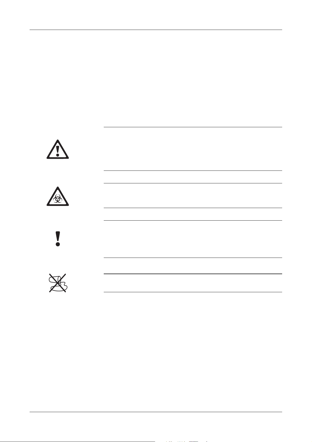
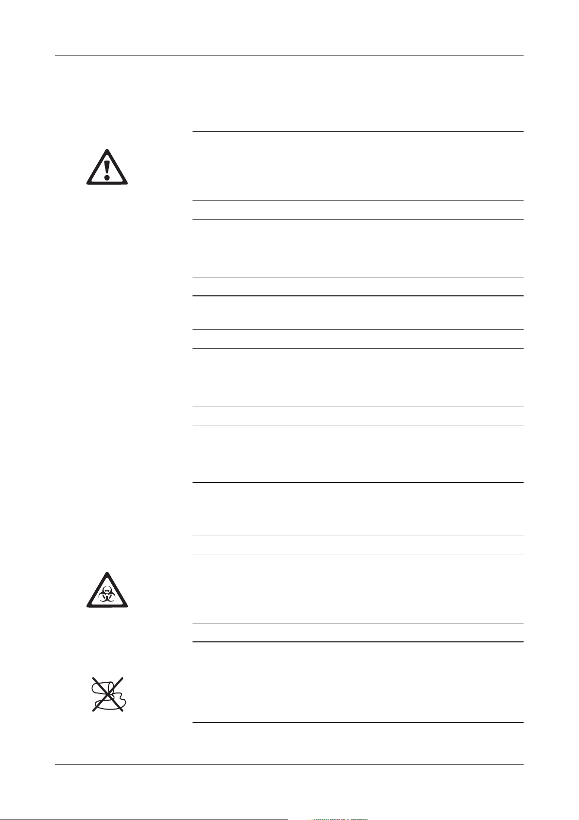
Warning
Indicates a possibly hazardous situation which, if not avoided, may result in death or
serious injury.
Examples of a “serious injury” include loss of eyesight, burn (high temperature, low
temperature), electric shock, bone fracture, or poisoning. These injuries require
medical assistance.
URISYS 2400
Biohazard
Samples containing material of human origin must be treated as potentially
infectious. The relevant laboratory guidelines on safe use must be observed.
Caution
Indicates a possibly hazardous situation which, if not avoided, may result in slight or
minor injuries, and/or damage to equipment.
“Minor injury” refers to injuries that may require medical assistance.
“Equipment” refers to extended damage to buildings, furniture, and so on.
Spillage
Avoid all liquid spills on the analyzer.
Roche Diagnostics
x Operator’s Manual · Version 1.0
Page 11
URISYS 2400
Safety information
Electrical safety
Connect the analyzer to grounded power outlets only (protection class 1). All
peripheral devices that are connected to the URISYS 2400 must comply with safety
standard IEC 950 (UL 1950) for information technology equipment, or with IEC
1010 (UL 3101) for laboratory use instruments.
Instrument in use
Keep hands or other objects away from the sampling probe area to prevent personal
injury while the instrument is in use. Do not touch parts of the analyzer other than
those specified.
User qualification
Only appropriately trained operators are qualified to operate the analyzer.
Correct use
Any disregard of the instructions in the Operator’s Manual may result in a safety risk.
Use the URISYS 2400 analyzer to analyze urine samples only. It is not intended for
any other application.
Transport
At least two persons must carry the analyzer, by holding the baseplates on the left
side and right side of the analyzer. Be careful not to hurt your hands or fingers when
putting the analyzer in place.
Environmental conditions
The URISYS 2400 is approved for indoor use only.
Biological safety
Liquid waste and strip waste are potentially biologically hazardous. Always wear
gloves if handling those materials. Do not touch parts of the analyzer other than
those specified. Consult your laboratory protocol for handling biohazardous
materials.
Spilling and cleaning
If a sample is spilled on the analyzer, wipe up immediately and apply disinfectant.
When handling the washing solution, ensure that you wear gloves and safety
goggles to avoid direct contact with the solution. If the solution contacts the body,
wash immediately with a large volume of water. Consult your laboratory protocol for
handling biohazardous materials.
Roche Diagnostics
Operator’s Manual · Version 1.0 xi
Page 12
URISYS 2400
Radio interference
URISYS 2400 is a class A device. In residential areas it may cause radio
interference. The user must take precautions as required.
Installation
Follow the specified installation conditions carefully. Otherwise, inaccurate results,
or damage to the analyzer may occur.
Waste
Handle liquid waste and used test strips properly, according to legislation on water
pollution, and on the treatment of drainage and waste matter.
Electromagnetic waves
Devices that emit electromagnetic waves may affect measured data, or cause the
analyzer to malfunction. Do not operate the following devices in the same room
where the analyzer is installed: mobile phone, transceiver, cordless phone, other
electrical devices that generate electromagnetic waves.
o
Operating and maintenance
Carefully follow the procedures specified in the Operator’s Manual for the
operation and maintenance of the analyzer. Leave maintenance of other areas to
trained Roche Technical Support personnel.
o
Calibration
Calibrate the analyzer every four weeks to ensure the analyzer operates
optimally. Failure to do so may lead to inaccurate results.
o
Test strips
Handle and store test strips according to the instructions provided by Roche
Diagnostics. Refer to the instructions in the package insert of the URISYS 2400
cassette.
o
Particular care must be taken when performing the following procedures:
Preparing and processing samples (routine, STAT and control)
Using the washing solution
Draining the liquid waste tank
Cleaning the TS transfer base
Disposing of used test strips
Cleaning the waste box
Roche Diagnostics
xii Operator’s Manual · Version 1.0
Page 13
URISYS 2400
D
C
B
A
E
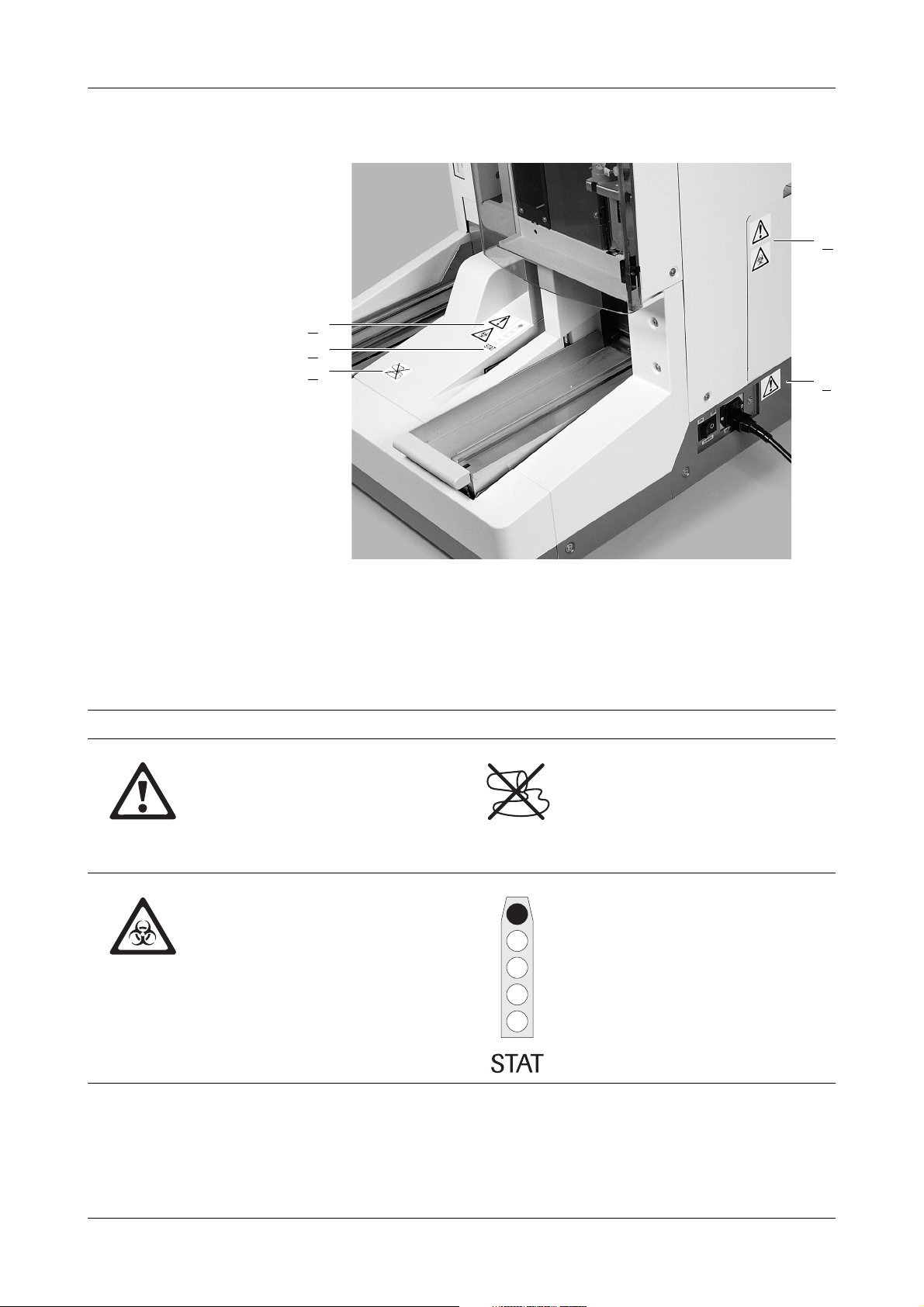
Figure 0-1 URISYS 2400 analyzer with labels
A
Housing
B STAT sample position
D Strip waste container door
E Power supply
C Housing before sampling area
Symbol Validity Symbol Validity
o STAT position
o Rack transfer
o STAT position
o Rack transfer
o Waste box
o TS transfer base
o Power supply
o Sampling probe
o STAT sample position
o Rack transfer
o Rinsing station
o Waste box
o TS transfer base
Roche Diagnostics
Operator’s Manual · Version 1.0 xiii
Page 14

URISYS 2400
Roche Diagnostics
xiv Operator’s Manual · Version 1.0
Page 15

Overview
Part A is an overview of the URISYS 2400.
A
Page 16

Page 17
URISYS 2400 1 Introduction to the system
Table of contents
Introduction to the system
This chapter contains an introduction to the URISYS 2400 analyzer.
In this chapter A
Description of the URISYS 2400 analyzer .........................................................2
Measuring principle ......................................................................................2
Chapter
1
Roche Diagnostics
Operator’s Manual · Version 1.0 A-1
Page 18

1 Introduction to the system URISYS 2400
Description of the URISYS 2400 analyzer
Description of the URISYS 2400 analyzer
The URISYS 2400 analyzer is a fully automated urinalysis system intended for
in vitro qualitative or semi-quantitative determination of urine analytes,
including pH, leukocytes, nitrite, protein, glucose, ketones, urobilinogen,
bilirubin, and erythrocytes. In addition, the analyzer determines specific
gravity, color, and clarity. The URISYS 2400 is intended for professional use
only.
The primary functions of the URISYS 2400 analyzer include:
o Sample identification
o Automatic dispensing of test strips
o Robotic pipetting of samples
o Controlled incubation period
o Photometric measurements
o Result memory
o Optional formats for data output
Measuring principle
The URISYS 2400 analyzer uses the URISYS 2400 cassette containing 400 test
strips. Each test strip has ten individual test pads that are used to test for
different substances or characteristics. The test strips are analyzed as they
move automatically through the analyzer. One strip is used per sample. When
a strip is dispensed for use, an aliquot of the urine sample is pipetted onto
each of the test pads. The test results are based on the measurement of
reflected light intensity. The specific gravity, color, and clarity of each sample
are also measured.
The URISYS 2400 is a fully automated reflectance photometer for in vitro
semi-quantitative measurements of urine test strips. The light sources (LED’s
[light-emitting diodes]) and reading times are optimized for the reaction
chemistry and color development that occur on the test pads.
The measuring head of the URISYS 2400 contains LED’s of three different
wavelengths. The test strip remains stationary at the measuring position as the
measuring head moves over each test pad. Measurement starts at the reference
plate, which is used to test the optical system.
The URISYS 2400 verifies that the test strip is properly positioned under the
measuring head, by measuring the reflected light. If a test strip is not properly
positioned under the measuring head, the URISYS 2400 displays a message.
Roche Diagnostics
A-2 Operator’s Manual · Version 1.0
Page 19
URISYS 2400 1 Introduction to the system
Description of the URISYS 2400 analyzer
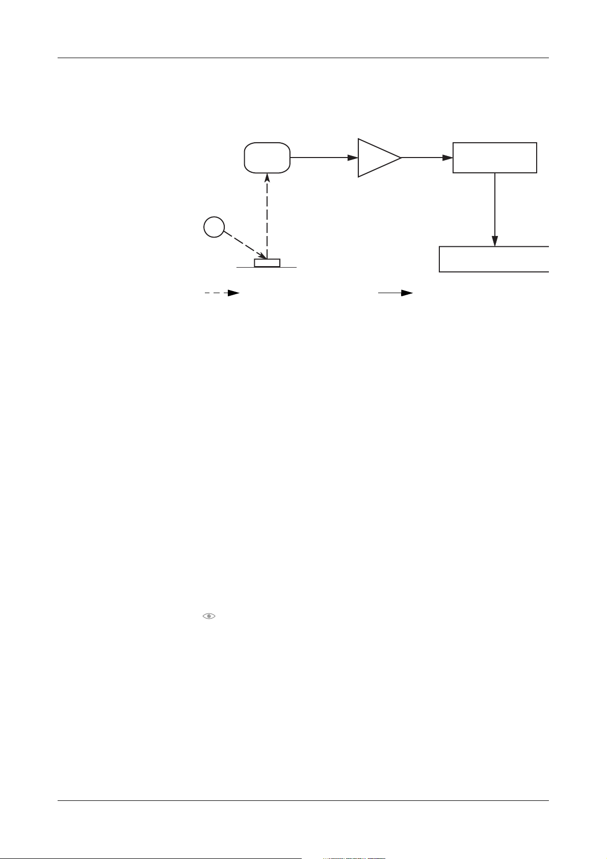
Reflected light is measured electro-optically, and the process is illustrated in
the following figure.
C
A
B
Optical transmission Electronic transmission
Figure A-1 Process of measuring
LED
A
B Te st pad
C Photodiode detector
An LED (
A) transmits light of a defined wavelength, at an optimum angle,
onto the surface of a test pad (
B). The light hits the surface of the test pad and
D
D Analog-to-digital converter
E Microprocessor
F Concentration result
E
F
is reflected with an intensity that is dependent on the color of the test pad.
A photodiode detector (
C), positioned directly above the test pad, receives the
reflected light. The photodiode detector transmits an analog electrical signal
to the analog-to-digital converter (
D), which changes the analog signal to a
digital value.
A microprocessor (
E) adjusts the digital value, based on a value from an
internal reference plate. It converts the digital value to a relative value by using
a calibration standard scale. Then, the microprocessor calculates a reflectance
value.
The semi-quantitative concentration result (
F) is determined by comparing
the reflectance value with the so-called range limits (parameter-specific
reflectance values stored in the analyzer). The full list of concentration range
values for all test parameters is shown in:
Table F-1 on page F-5
The results are stored in the memory and can be printed, saved to a diskette,
or sent to another computer.
Each of the three LED’s transmits light of a different wavelength. The use of
different wavelengths improves the results that are obtained from measuring
each of the test strip parameters. The wavelengths used to measure the
different parameters are listed in the table below.
Roche Diagnostics
Operator’s Manual · Version 1.0 A-3
Page 20

1 Introduction to the system URISYS 2400
Description of the URISYS 2400 analyzer
Test parameter Measuring wavelength (nm)
pH 555, 620
Leukocytes 555
Nitrite 555
Protein 555
Glucose 555
Ketones 555
Urobilinogen 555
Bilirubin 555
Erythrocytes 555, 620
Color 470, 555, 620
Table A-1 Wavelengths used to measure the reflectance values
The photometric reflectance measurement for all of the test parameters is
performed after an incubation time of 60 seconds. As with previous urine
analyzers from Roche Diagnostics, compensation for intrinsic urinary color,
which is a recognized interfering factor, is made through the measurement of
a blank compensation pad on the test strip. The compensation pad assists in
the prevention of false positives when a urine sample is strongly colored.
The URISYS 2400 determines the urine color by evaluating the reflectance
values of all three measuring wavelengths (470 nm, 555 nm, and 620 nm) on
the compensation pad. Color results are reported as PALE YELLOW,
YELLOW, AMBER, BROWN, ORANGE, RED, GREEN, or OTHERS.
The measurement of specific gravity (SG) is performed in a flow cell that is
filled with a urine sample during aspiration of the sample. An LED (650 nm)
transmits light to the flow cell. A charge-coupled device (CCD) determines
the angle of total reflection. The refractive index of the sample is calculated
from the angle of total reflection using a calibration curve. Transformation
into the SG value is performed by a nomogram stored in the analyzer.
The flow cell that is used to measure specific gravity also determines the
clarity of the sample. However, light of a different LED is used to measure
clarity. This LED (660 nm) transmits light to the flow cell, and the amount of
light that passes through the flow cell is measured.
The system is blanked (zeroed) during the washing process, between sample
measurements, by setting the water transmission to 100%. The transmission
values of samples are transformed to clarity results (CLEAR, LIGHT TURBID
or TURBID), by using the clarity range table that is programmed in the
software of the URISYS 2400.
Roche Diagnostics
A-4 Operator’s Manual · Version 1.0
Page 21

URISYS 2400 1 Introduction to the system
Description of the URISYS 2400 analyzer
When a sample has been pipetted onto the test pads of a test strip, and the
specific gravity and clarity have been measured, the remaining urine is ejected
into the rinse station. The needle and the flow cell are washed with water
before the next sample is taken.
Roche Diagnostics
Operator’s Manual · Version 1.0 A-5
Page 22

1 Introduction to the system URISYS 2400
Description of the URISYS 2400 analyzer
Roche Diagnostics
A-6 Operator’s Manual · Version 1.0
Page 23

System description
Part B is the system description of the URISYS 2400.
B
Page 24

Page 25

URISYS 2400 2 Hardware
Table of contents
Hardware
This chapter contains the description of the system hardware.
In this chapter B
Hardware description ........................................................................................2
Standard accessories .....................................................................................4
Additional items ............................................................................................5
Installation .........................................................................................................5
Basic requirements .......................................................................................5
Surface and space measurements ............................................................5
Power supply ............................................................................................6
Water supply .............................................................................................6
Assemble the parts .........................................................................................7
Set up the water supply tank ..................................................................7
Liquid waste tank ....................................................................................8
TS transfer base ........................................................................................8
External printer ............................................................................................9
External host connection ............................................................................9
Environmental conditions .........................................................................10
Chapter
2
Roche Diagnostics
Operator’s Manual · Version 1.0 B-1
Page 26

2 Hardware URISYS 2400
Hardware description
Hardware description
The URISYS 2400 analyzer consists of several major components:
o Rack transport system
o Liquid handling system
o Test strip cassette compartment
o Automated test strip processing area
o 3-wavelength reflectance photometer
o Combined, flow-through refracto-/turbidimeter
o User interface screen
o Inbuilt computer
o Battery-buffered memory
o Diskette drive (for MS-DOS compatible diskettes)
Roche Diagnostics
B-2 Operator’s Manual · Version 1.0
Page 27
URISYS 2400 2 Hardware
Hardware description
C
B
A
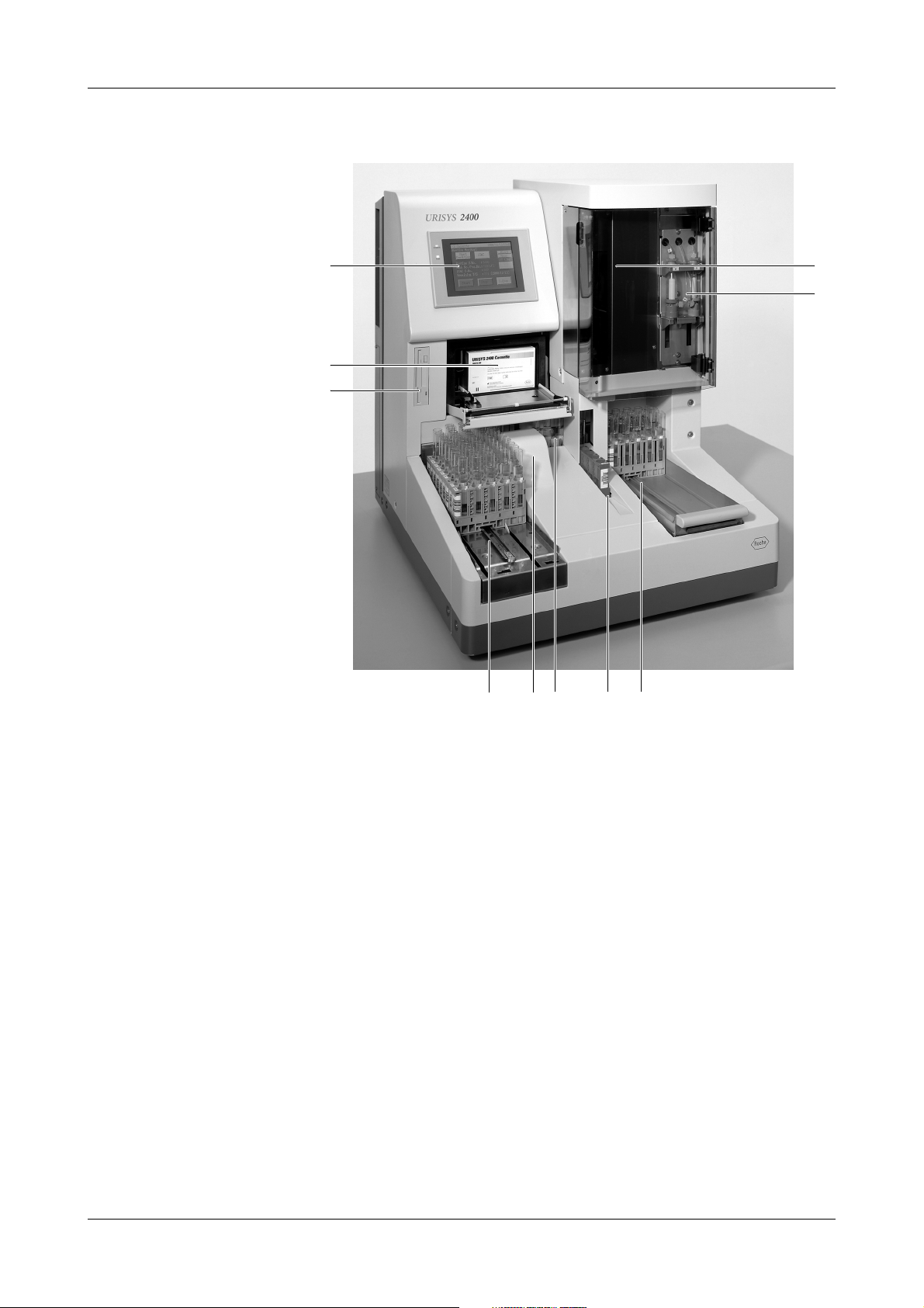
Figure B-1 The URISYS 2400 analyzer
Diskette drive
A
B URISYS 2400 test strip cassette
compartment
C Touch screen
D Pipette mechanism
E Wash and sample syringes
D
E
FGHIJ
F Rack output line
G STAT sampling position
H Rack cross-feed line
I Barcode reader
J Rack input line
Roche Diagnostics
Operator’s Manual · Version 1.0 B-3
Page 28

2 Hardware URISYS 2400
Hardware description
Standard accessories
The standard accessories that accompany the URISYS 2400 analyzer are:
o Water supply tank with a liquid level detector
o Water supply tube with filter
o Two rack trays
o Liquid waste tube 5 m (16.4 ft) length
o Strip waste container
o Standard maintenance kit (O-rings, seals)
o Fuses
o Power cord
o Three software installation diskettes
o Operator’s Manual (English version)
Water supply tank with liquid
level detector
Rack trays Two identical trays are supplied with the analyzer. Each tray holds up to 15
Strip waste container Used test strips are deposited in a strip waste container that has a minimum
The water supply tank that supplies deionized water to the analyzer is located
externally. It has a maximum capacity of 5 L (5.3 qts). This volume is
sufficient to process approximately 1000 samples.
racks at one time. One tray is used to load the racks onto the rack input line.
The second tray is used as a stationary rack output tray during sample
processing and serves to remove racks from the rack output line.
capacity of 420 test strips. (The capacity is calculated on the basis of the
contents of one URISYS 2400 cassette plus a safety margin.)
The strip waste container is located on the right side of the analyzer, behind
the door panel. The container is designed to minimize the contact an operator
has with potentially infectious and toxic materials.
When the strip waste container is full, a message is displayed on the touch
screen.
Roche Diagnostics
B-4 Operator’s Manual · Version 1.0
Page 29
URISYS 2400 2 Hardware
Installation
Additional items
Items that are necessary or optional for the installation and operation of the
URISYS 2400 analyzer, but are not supplied with the analyzer, are:
o Liquid waste tank (with or without an optional overflow sensor)
o Racks
o Sample tubes
o Wash in g solu tion
o URISYS 2400 cassette
o URISYS 2400 calibration strip
o External printer and standard printer cable (parallel/Centronics interface)
o Waste container cartons
o Serial interface (host) cable
o 1.44 MB diskette for storage of data
Installation
Basic requirements
Surface and space
measurements
Read this manual carefully before installation, to ensure correct operation of
the analyzer.
If you have any questions after initial installation, contact Technical Support.
Only trained Roche Technical Support personnel, or similarly qualified personnel
supervised by authorized service agents of Roche Diagnostics, are qualified to
install the URISYS 2400 analyzer.
At least two persons must carry the analyzer, by holding the baseplates on the left
side and right side of the analyzer. Be careful not to hurt your hands or fingers when
putting the analyzer in place.
Follow the specified installation conditions carefully. Otherwise, inaccurate results,
or damage to the analyzer may occur.
The following surface and space requirements must be met for the use of the
URISYS 2400 analyzer, and the proper ventilation of the analyzer when it is in
use:
o 5 cm (2.0 inches) or more (rear)
o 20 cm (7.9 inches) or more (left side)
o 30 cm (11.8 inches) or more (right side)
Use a table that is able to support the mass of the analyzer, which is
approximately 85 kg (187 lbs). The table must be level. Any inclination must
be less than 1.5 degrees in every direction.
Roche Diagnostics
Operator’s Manual · Version 1.0 B-5
Page 30
2 Hardware URISYS 2400
Installation
Power supply A standard 230 V/50 Hz or 115 V/60 Hz power line is required to operate the
analyzer. It must be connected to a grounded power supply socket (protection
class 1).
Although the maximum power consumption of the instrument is 200 VA, the
external power supply should fulfill the following minimum requirements to
cover for peaks at switching on.
Electric power supply capacity:
o Minimum 500 VA
o Minimum 5 Amp, 3-pin power supply socket
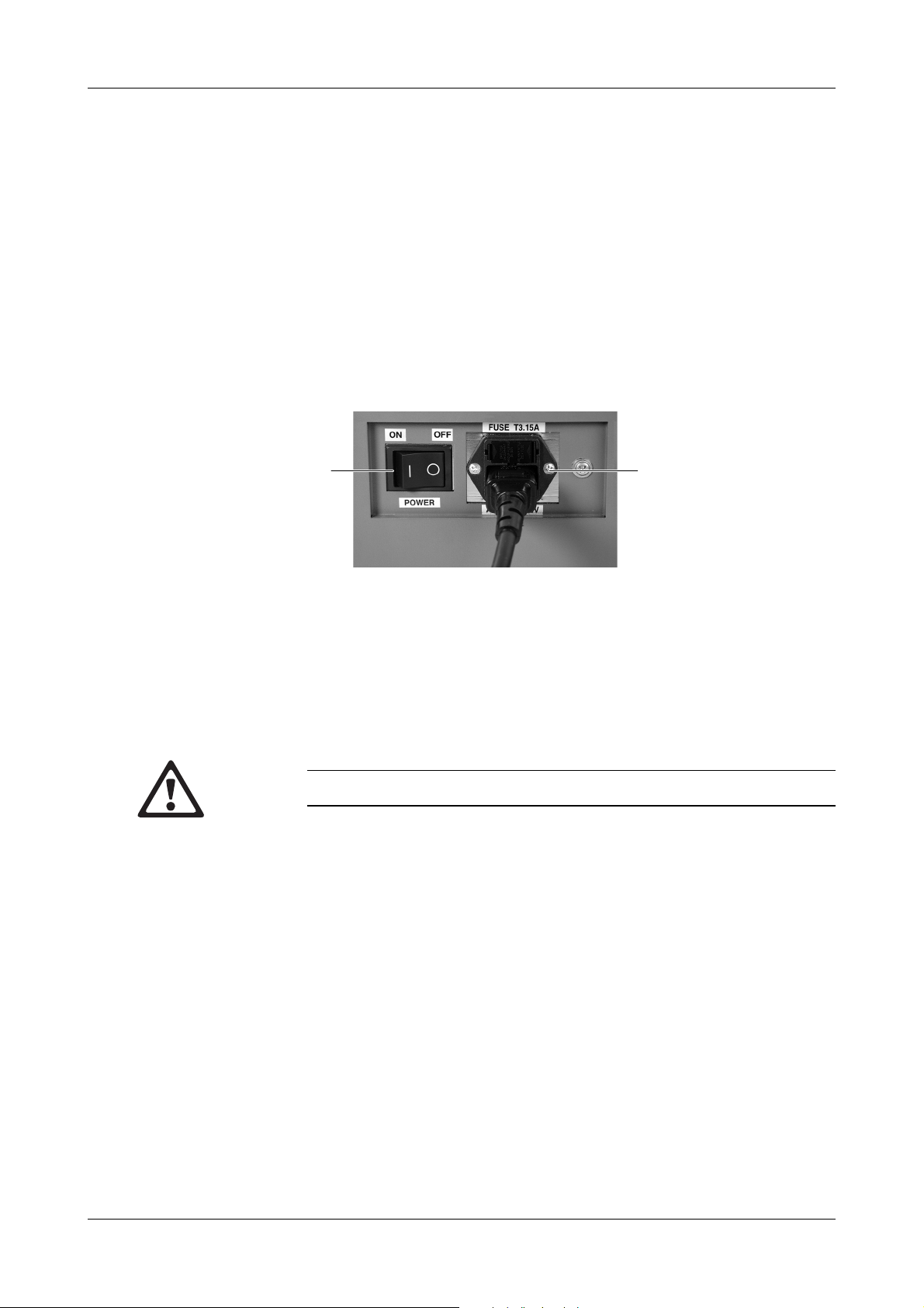
The power switch and power supply socket are located on the right side of the
analyzer.
AB
Figure B-2 Power switch and power supply socket
Power switch B Power supply socket
A
Water supply An external water supply tank for deionized water is supplied with the
URISYS 2400. The deionized water must be germ free and have an electric
conductance value that is less than or equal to 1 µS/cm.
Do not connect the analyzer directly to a pressurized water supply.
Roche Diagnostics
B-6 Operator’s Manual · Version 1.0
Page 31

URISYS 2400 2 Hardware
Installation
Assemble the parts
Set up the water supply
tank
The external water supply tank provides water to the analyzer for washing.
The tank has a volume of approximately 5 liters (5.3 quarts), which allows for
the measurement of about 1000 samples.
a To set up the water supply tank
1 Fill the tank with deionized water.
2 Connect the cable of the liquid level detector to the water level connection
on the analyzer.
3 Connect the water supply tube with filter to the water inlet connection on
the analyzer.
4 Press the water tube into the slit of the rubber stopper that is on top of the
liquid level detector, so the filter, at the end of the water supply tube will be
long enough to reach the bottom of the tank.
5 Put both the liquid level detector and the water supply tube with filter
through the opening of the tank, so the filter touches the bottom of the
tank, while the level detector with rubber stopper align vertically into the
tank.
B
A
Figure B-3 Connecting the water supply tank and liquid waste tank to the analyzer
A Water inlet connection
B Liquid waste tube connection
If the water is contaminated by the growth of bacteria or algae, it may result in faulty
liquid detection and rinsing in the pipetting mechanism and rinse circuits of the
analyzer.
C Connector for water level detector
D Connector for liquid waste level detector
C
D
Roche Diagnostics
Operator’s Manual · Version 1.0 B-7
Page 32

2 Hardware URISYS 2400
Installation
Liquid waste tank The liquid waste tank is located outside the analyzer. The capacity of the tank
depends on the specific tank that is used. The tank must have a volume of at
least 5 L (5.3 qts). An overflow sensor is available as an option.
A 5 m (16.4 ft) liquid waste tube is supplied for the connection of the liquid
waste tank to the analyzer.
a To set up the liquid waste tank
1 Ensure the liquid waste tank is empty before use. The liquid waste tank
must be positioned well below the level of the analyzer, to allow for the
reliable flow of the liquid waste into the tank.
2 Connect the liquid waste tube to the drain socket on the analyzer. If
necessary, shorten the liquid waste tube to ensure smooth and even flow.
3 If an overflow sensor is used, connect it to the drain level connector on the
analyzer and place it into the liquid waste tank.
TS transfer base
a To set up the TS transfer base and the strip waste container
1 Open the strip waste container door on the right side of the analyzer.
2 Insert the TS transfer base smoothly to its end position, and ensure that it
is positioned correctly.
Figure B-4 Inserting the TS transfer base into the URISYS 2400 analyzer
3 Turn the screw on the TS transfer base until it locks to secure the base.
4 Insert a waste box carton into the strip waste container and place it into its
correct position.
Roche Diagnostics
B-8 Operator’s Manual · Version 1.0
Page 33

URISYS 2400 2 Hardware
Installation
5 Close the strip waste container door.
Figure B-5 Installing the strip waste container
External printer
External host connection
An external printer can be connected via a standard parallel interface
(Centronics type).
Recommended printers are:
Country Printer
For Japan: EPSON VP600
FUJITSU M3388C
For Europe: FUJITSU M3388B
FUJITSU DL 3700 Pro
For USA: FUJITSU M3388A
Table B-1 Table of recommended printers
If another type of printer is used, ensure that it is compatible with the
analyzer.
The analyzer can be connected to a host computer via a serial interface using
ASTM protocol.
For specifications of serial host interfacing, contact Technical Support.
Roche Diagnostics
Operator’s Manual · Version 1.0 B-9
Page 34

2 Hardware URISYS 2400
Installation
Environmental conditions
The URISYS 2400 analyzer must be used in an environment that meets the
following conditions:
o Free from excessive dust
o Well-ventilated area
o Not exposed to direct sunlight
o Floor that is level (with an inclination of less than 1.5 degrees in every
direction) and firm
o Table that can support the mass of the instrument, which is approximately
85 kg (187 lbs)
o Ambient temperature ranging from 15-30°C (59-86°F), with an acceptable
variation of ±2°C (±3°F) during measurement
o Relative humidity ranging from 20% to 80%, without moisture
condensation
o Free from vibrations
o Availability of a 3-pin power supply socket within 3 m (9.8 ft) of the
analyzer
o Free from abrupt mains voltage fluctuation (±10 V)
o Well-distanced from a machine generating a high frequency voltage (for
example, a centrifuge)
o Free from electromagnetic wave interference
Roche Diagnostics
B-10 Operator’s Manual · Version 1.0
Page 35

URISYS 2400 3 Software
Table of contents
Software
This chapter describes the URISYS 2400 software.
In this chapter B
Installation .......................................................................................................12
The URISYS 2400 touch screen ..................................................................13
Setting the parameters .................................................................................16
Test parameters ......................................................................................17
Sieve and abnormal values ....................................................................17
Print order ..............................................................................................18
Controls ..................................................................................................19
Range table .............................................................................................21
Units ........................................................................................................24
System parameters .......................................................................................24
Sample barcode ......................................................................................25
Printer .....................................................................................................25
COMM. parameter ..............................................................................26
Date/Time ...............................................................................................26
Password .................................................................................................27
Register the wash rack ...........................................................................27
Parameter media ..........................................................................................28
Load ........................................................................................................28
Save .........................................................................................................28
Print ........................................................................................................28
Chapter
3
Roche Diagnostics
Operator’s Manual · Version 1.0 B-11
Page 36

3 Software URISYS 2400
Installation
Installation
The software supplied with the analyzer supports all functions of the
URISYS 2400 analyzer. Specific functions are password-protected to avoid
accidental modifications.
The English software is pre-installed and ready for use on delivery of the
analyzer.
In case re-installation of the software is necessary, proceed as follows.
a To install the software
1 Save the system parameters, test parameters, routine sample results, STAT
sample results, control results and the alarm trace onto a diskette as safety
backup.
“Setting the parameters” on page B-16
“Data of routine and STAT samples” on page C-21
“Control sample data” on page C-28
“Handle alarms” on page E-3
2 Switch off the power.
3 Insert System Disk 1 into the diskette drive.
4 Switch on the power, located on the right side of the analyzer. The [Wait]
screen is displayed.
5 While the [Wait] screen is displayed, press both the lower left and lower
right corners of the LCD panel simultaneously. The [System Menu] screen
is displayed.
6 Press <Transmit Mode>.
7 Press <Tool Transmit>.
8 Follow the instructions on the screen to complete the installation.
9 If necessary, restore the system parameters, test parameters, routine sample
results, STAT samples results, and control results from the backup diskette.
Step 1
Roche Diagnostics
B-12 Operator’s Manual · Version 1.0
Page 37

URISYS 2400 3 Software
Installation
The URISYS 2400 touch screen
The touch screen has been designed to make navigation through the menus
consistent and convenient. Press the buttons on the touch screen once to
perform the various functions. Operators wearing gloves can easily use the
touch screen. A special pointer can be used to operate the keyboard displayed
on the touch screen, if necessary.
Basic screen composition Generally, the status of the analyzer is indicated in the upper left of the yellow
line of the main screen. There are three main status types. For information on
the different status types displayed on the touch screen, see:
Table B-2 on page B-13
Other status types are displayed during special operations.
The date and time are displayed in the upper right of the screen.
Figure B-6 Example of a touch screen
Status type Explanation
Stand-By The analyzer must always be in Stand-By status for
the processing of data, inputting of criteria, or
setting the parameters. The analyzer is idle in this
status.
Operation The analyzer processes samples in this status. This
status allows the operator to load additional samples
without interrupting sampling and measurement of
samples currently being processed.
Sampling Stop
Table B-2 Main status types displayed on the touch screen
Roche Diagnostics
Operator’s Manual · Version 1.0 B-13
The status of the analyzer changes to Sampling Stop
when there are no more racks on the rack input line
or to S.Stop when the analyzer cannot continue with
a procedure. This generally coincides with a
message that indicates the reason for the stop.
Page 38

3 Software URISYS 2400
Installation
Immediately below the line indicating the status of the analyzer, the name of
the current screen is displayed. For example, the name of the screen displayed
above is [Routine Monitor].
Figure B-6 on page B-13
Press <Home> on the initial [Copyright] screen to display the [Routine Monitor]
screen.
There are a number of buttons that consistently appear on the screens. The
following table summarizes these buttons and their functions.
Button Explanation
<Home> Press this button to display the [Routine Monitor] screen.
<Alarm> This button flashes to signal an alarm. Press this button to
read the message.
<Menu> Press this button to display the [Menu] screen.
<PgUp> Page up. Press this button to return to the previous screen.
<CLR> The data entered is cleared. The CLR button only works
before the Enter button is pressed.
<Cancel> Cancels any data that has been entered and returns to the
previous screen without having made any changes. The
Cancel button only works before the Enter button is pressed.
<OK> Confirms the data on-screen and proceeds to the next
screen.
“<“ Press < to move through the different fields.
“>“ Press > to move through the different fields.
<+> Increases values on the touch screen.
<-> Decreases values on the touch screen.
<>
Table B-3 Main buttons displayed on the touch screen
Enter. Press this button to confirm the newly entered data.
Roche Diagnostics
B-14 Operator’s Manual · Version 1.0
Page 39

URISYS 2400 3 Software
Installation
As the operator navigates through the different screens, there are various
windows that can appear. These serve different functions, such as
confirmation of a selection. The figure shows an example:
Figure B-7 Example of a window that can appear on the touch screen
Some of the buttons for selecting settings work with a toggle function.
Roche Diagnostics
Operator’s Manual · Version 1.0 B-15
Page 40

3 Software URISYS 2400
Installation
Setting the parameters
A number of parameters can be set individually according to laboratory
requirements if they deviate from the default factory settings.
The settings are automatically stored so that the data or analytical parameters
do not need to be re-specified each time, except when required. They can be
printed or saved to a diskette for documentation.
If any mistakes related to the consistency of values occurred during setting of
parameters, the corresponding error alarm message does not appear until <Start>
is pressed for starting analysis. Check the alarm and correct the settings.
The setting of parameters is only possible when the analyzer is in Stand-By
status. For starting the analyzer, see:
“System start” on page C-4
Parameters
Test Parameters System Parameters Parameter Media
Sieve & Abnormal
Print Order
Controls
Range Table
Units
Figure B-8 System hierarchy chart of the progression through the different
screens of the Parameters menu
Sample Barcode
Printer
COMM.Parameter
Date / Time
Password
Regist. Wash Rack
Load Parameters
Save Parameters
Print Parameters
Roche Diagnostics
B-16 Operator’s Manual · Version 1.0
Page 41

URISYS 2400 3 Software
Installation
Test para me t er s
a To set test parameters
1 Press <Menu> on the [Routine Monitor] screen. The [Menu] screen is
displayed.
2 Press <Parameters>. The [Parameters] screen is displayed.
3 Press <Test Parameters>. The [Test Parameters] screen is displayed.
4 Press any of the following five buttons to gain access to the option you
require:
o <Sieve & Abnormal>
o <Print Order>
o <Controls>
o <Range Table>
o <Units>
Sieve and abnormal
values
Use the sieve settings to define the criteria for a flag (S) on the corresponding
test parameter result. These flags can be used to identify urine samples to be
examined by additional methods, for example, sediment microscopy.
Use the abnormal settings to define the criteria that indicate potentially
pathological values. An asterisk (*) flags the corresponding test parameter
results.
The concentration values which are specified on the screen represent the
lowest concentration ranges from which on the test parameter results are
flagged.
For more information, see:
Table E-1 on page E-2
Figure B-9 Sieve & Abnormal screen
Roche Diagnostics
Operator’s Manual · Version 1.0 B-17
Page 42

3 Software URISYS 2400
Installation
a To set the criteria for defining sieve and abnormal values
1 Press <Sieve & Abnormal> on the [Test Parameters] screen. The [Sieve &
Abnormal] screen is displayed listing the sieve criteria for each test.
2 Press <Select> to change the display of the items from sieve to abnormal
criteria and back.
3 Press <Set> to change the criteria. The [Password] window appears.
4 Enter the 4-digit password using the keyboard on the screen.
5 Press <Enter>. The [Sieve & Abnormal Setting] screen is displayed with
both the sieve and abnormal values listed for each test parameter,
beginning with specific gravity (SG).
6 Press <Test> to select another test parameter.
7 Press “<” or “>” to select sieve or abnormal settings.
8 Press <+> or <-> to select the desired concentration range.
9 Press <Enter> after each selection to accept the chosen values.
10 Press <PgUp> to return to the [Sieve & Abnormal] screen and check if the
settings correspond to your requirements.
11 Press <PgUp> to return to the [Test Parameters] screen.
Print order The operator can define the order of the test parameters on the screen and on
the result printout, in order from 1 to 12. If an item is not to be printed, enter
zero.
Figure B-10 Screen showing Print Order settings and options
Roche Diagnostics
B-18 Operator’s Manual · Version 1.0
Page 43

URISYS 2400 3 Software
Installation
a To set the print order
1 Press <Print Order> on the [Test Parameters] screen. The [Print Order]
screen is displayed.
2 Enter the test parameter order if the requirements of the laboratory differ
from the default settings.
3 Press “<” or “>” to move through the different fields.
4 Press <Enter> after each entry.
5 Press <PgUp> to return to the [Test Parameters] screen.
Controls The operator can define the following:
o Control sample rack number
o Position of the control samples on the rack
o Control sample name
o Lot number
When the control sample rack number has been registered, the analyzer
automatically recognizes this rack as a rack carrying urine control samples,
and measures the samples like normal samples; however, the results are stored
in a special control sample data memory.
For each specified position on the control rack, a separate memory for 100
results is available. Up to three different controls can be measured in one rack.
The specified position on the rack of each control level must be used each
time to avoid the mixing of results in the assigned memory.
a To specify the control rack number and control sample rack
position
1 Press <Controls> on the [Test Parameters] screen. The [Controls] screen is
displayed.
2 Press <Regist. Control Rack>. The [Regist. Control Rack] screen is
displayed.
3 Enter the range of the control rack ID numbers in the fields provided. The
control rack ID numbers must consist of five digits and overlapping ranges
(for example, with routine racks) are not allowed.
If the 5-digit number of the chosen rack is not known, read and print the rack ID via
the Barcode Check function (see “Checks” on page C-41).
4 Press <Enter> after each value has been entered.
5 Enter the position number on the rack for each level of control sample, for
example, position one for normal level and position two for abnormal
level. The input positions range from 1 to 5 on the registered rack, or zero.
If a level is not to be measured, enter zero.
Roche Diagnostics
Operator’s Manual · Version 1.0 B-19
Page 44

3 Software URISYS 2400
Installation
6 Press <Enter> after each entry.
7 Press <PgUp> to return to the [Controls] screen.
Mark the specified rack as a control rack. Do not use the control rack for
routine samples, otherwise the routine sample results will be stored in the
control data memory.
a To specify the control name and lot number
1 Press <Control Name/Lot No.> on the [Controls] screen. The [Control
Name/Lot No.] screen is displayed.
2 Press <Level> to select a level, for example, Level 1, Level 2 or Level 3.
3 Type the name of the control material, using a maximum of 16
alphanumeric characters. Press <Enter>.
4 Type the Lot No., using a maximum of 10 digits.
5 Press <Enter> after each entry.
6 Press <Level> again to enter the Name and Lot No. for the remaining
levels.
7 Repeat steps 3-5.
8 Press <PgUp> twice to return to the [Test Parameters] screen.
Roche Diagnostics
B-20 Operator’s Manual · Version 1.0
Page 45

URISYS 2400 3 Software
Installation
Range table The operator can view the concentration ranges, reflectance values,
wavelengths and compensation data for each test parameter. The operator
gains access to the range and reflectance values by using the password that is
supplied with the analyzer.
Figure B-11 Screen showing Range Table settings and options
The wavelength data (W) that are displayed are fixed values. These values
cannot be changed.
The compensation data (C) designate factors for the compensation of the
intrinsic urine color, for example, 0 means no color compensations. Higher
numbers mean stronger compensation.
Changing ranges leads to result reports which differ from the default
concentration ranges as shown in:
Table F-1 on page F-5
Changing reflectance values leads to different evaluation sensitivities of the
respective test parameters. Lowering the reflectance value of the negative (NEG)
range leads to a decrease of the sensitivity of the test evaluation, and vice versa. In
this way, the sensitivity can be adjusted to the requirements of the individual
laboratory.
The correctness of results obtained after the user has altered the ranges or
reflectance values is not warranted by Roche Diagnostics. The user is responsible
for validating the consistency of results after changes have been made.
The concentration ranges and reflectance values can be reset to the default
values using the <Default> button.
Roche Diagnostics
Operator’s Manual · Version 1.0 B-21
Page 46

3 Software URISYS 2400
Installation
a To change the range values
1 Press <Range Table> on the [Test Parameters] screen. The [Range Table]
screen is displayed.
2 Press <Test> to select the test parameter to be viewed. For each test
parameter, the range and reflectance values can be changed.
3 Press <Set Range> to change the range. The [Password] window appears.
4 Enter the 4-digit password.
5 Press <Enter>. When the correct password is entered, the [Set Range]
screen is displayed.
6 Press <Test> to select a test parameter.
7 Enter the range values. Press “<” or “>” to move through the different
fields.
8 Press <Enter> after each value is entered.
9 Repeat steps 6-8 if the ranges of other test parameters need to be changed.
10 Press <PgUp> to return to the [Range Table] screen.
o
The screen allows for eight ranges to be set for each parameter. However, not all
of the ranges are used by the default settings.
o
If ranges are changed for conventional concentration units, these changes are
not transferred to the SI concentration units memory, and vice versa. To be
consistent, corresponding changes must be made in both range tables. (See
Table F-1 on page F-5.)
a Using arbitrary units
If arbitrary units (1+, 2+, 3+) should be used instead of concentration values
or in addition to concentration values, proceed as follows:
1 Call up the [Set Range] screen.
2 Press <Test> to select a test parameter.
3 Enter the arbitrary unit in the corresponding field and delete the
concentration value by pressing <Space> if you want to replace the
conventional or SI units.
4 Enter the arbitrary unit in the corresponding field without deleting the
concentration value if you want to used combined units, for example,
“2+ 25”.
If combined units are used for the parameter Glucose, the entry of “4+1000” is not
possible because of the limitation of 5 digits per field. Use “4+999” instead.
Roche Diagnostics
B-22 Operator’s Manual · Version 1.0
Page 47

URISYS 2400 3 Software
Installation
a To change the reflectance values
1 Press <Set Reflect>. on the [Range Table] screen. The [Password] window
appears.
2 Enter the 4-digit password.
3 Press <Enter>. When the correct password is entered, the [Set Reflectance]
screen is displayed.
4 Press <Test> to select a test parameter.
5 Enter the new reflectance values between the indicated values. Apply
moderate changes and validate the effect to the evaluation sensitivity.
6 Press <Enter> after each value is entered.
7 Repeat steps 4-6 if reflectance values of other test parameters need to be
changed.
8 Press <PgUp> to return to the [Range Table] screen.
o
The screen allows for eight values to be set for each parameter. However, not all
of the values are used by the default settings.
o
Reflectance values that have been changed will be marked with a “#” flag on
the [Range table] screen as well as in the Parameter Settings printout. This flag
will also appear with the corresponding test parameter on the result printout.
a To set default concentration ranges and reflectance values
1 Press <Default> on the [Range Table] screen. The [Password] window
appears.
2 Enter the 4-digit password.
3 Press <Enter>. When the correct password is entered, the [Default]
window appears to confirm the change to the default settings.
4 Press <OK> to confirm. The changed concentration ranges and reflectance
values are set to default.
5 Press <PgUp> to return to the [Test Parameters] screen.
Roche Diagnostics
Operator’s Manual · Version 1.0 B-23
Page 48

3 Software URISYS 2400
Installation
Units
a To select the concentration units
The operator can select the units for reporting results (conventional or SI).
1 Press <Units> on the [Test Parameters] screen. The [Units] screen is
displayed. The units currently in use are displayed.
2 Press <Units> to change the type of units to be displayed on the screen and
on the printouts, and to be sent to the host computer. The [Confirmation]
window appears.
3 Press <OK> to change units.
When the units are changed, results are reported in the newly chosen units.
Therefore, it is important to set units before starting measurements. The change of
units also applies when re-printing previously measured results.
System parameters
The operator can select six system parameter settings. They are:
o Sample barcode
o Printer (includes the paper length, the number of samples printed per
page, and the page heading)
o Communication
o Date and time
o Password
o Registration of the wash rack
a To set system parameters
1 Press <System Parameters> on the [Parameters] screen. The [System
Parameters] screen is displayed.
Roche Diagnostics
B-24 Operator’s Manual · Version 1.0
Page 49

URISYS 2400 3 Software
Installation
Sample barcode
a To select the type of barcode
1 Press <Sample Barcode> on the [System Parameters] screen. The [Sample
Barcode] screen is displayed.
2 Press <Sample Barcode> to enable or disable the use of a barcode.
If sample barcode is enabled, any sample with no barcode label or an unreadable
barcode, results in an alarm message. In this case, samples are still tested. If sample
barcode is disabled, no sample barcodes are read.
3 Press <Code39 C/D>, <NW7 C/D>, and <ITF C/D> to enable or disable
the use of a check digit function for each type of barcode. A [Warning]
window will alert the operator of the increased probability for misreads
when check digits are disabled.
Printer
4 Press <PgUp> to return to the [System Parameters] screen.
If using an ITF barcode type, Roche/Hitachi recommends its use only with a check
digit function.
a To define printer settings
1 Press <Printer> on the [System Parameters] screen. The [Printer] screen is
displayed.
2 Press <Paper Length> to define the paper size.
3 Press <Samples/Page> to define the number of samples to be printed per
page.
4 Press <Headline edit>. The [Headline edit] screen is displayed.
5 Enter the new headline (up to 26 characters per line).
6 Press <Enter> at the end of each line.
7 Press <PgUp> twice to return to the [System Parameters] screen.
Roche Diagnostics
Operator’s Manual · Version 1.0 B-25
Page 50

3 Software URISYS 2400
Installation
COMM. parameter
a To define the communication parameters
Changing the settings is only possible when the analyzer is set to “Host Off-line”
(see “Start conditions before sampling” on page C-5).
1 Press <COMM. Parameter> on the [System Parameters] screen. The
[COMM. Parameter] screen is displayed.
2 Press <Baud Rate>, <Parity>, <Bits Per Char.>, and <Stop Bit> to select
the settings for communicating with the host computer.
These settings must match the corresponding settings of the host computer. Only
specialists or trained supervisors should change these settings.
3 Press <PgUp> to return to the [System Parameters] screen.
Date/Time The operator can change the format of the date and time, and set the correct
local dates, which are displayed on the touch screen and reported with the
measurement results and in the alarm messages.
a To select format and local settings for date and time
1 Press <Date/Time> on the [System Parameters] screen. The [Date/Time]
screen is displayed.
2 Press <Order> to change the format of the date.
3 Press <Time> to change the format of the time from 12 hour to 24 hour.
4 Enter the correct local date and time.
5 Press <Enter> after each entry.
6 Press <PgUp> to return to the [System Parameters] screen.
Roche Diagnostics
B-26 Operator’s Manual · Version 1.0
Page 51

URISYS 2400 3 Software
Installation
Password The operator can change the password used to gain access to the
[Sieve & Abnormal Setting], [Set Range], [Set Reflectance], and [Default]
screens. The password is identical in each case. Only numerical characters can
be used.
a To change the password
1 Press <Password> on the [System Parameters] screen. The [Password]
window appears.
2 Enter the old (current) 4-digit password.
3 Enter the new 4-digit password.
4 Re-enter the new password.
5 Press <Enter> after each entry.
6 Press <PgUp> to return to the [System Parameters] screen.
Register the wash rack The operator can define the ID of the rack to be used for washing. If the
washing procedure is performed using a rack on the rack input line, the
analyzer recognizes the specified rack and performs the washing procedure.
a To register the wash rack
1 Press <Regist. Wash Rack> on the [System Parameters] screen. The
[Regist.Wash Rack] screen is displayed.
2 Enter the consecutive range of the wash rack ID numbers in the fields
provided. The wash rack ID numbers must consist of five digits, and
overlapping ranges (for example, with routine sample racks) are not
allowed.
If the 5 digit number of the chosen rack is not known, read and print the rack ID via
the Barcode Check function (see “Checks” on page C-41).
3 Press <Enter> after each entry.
4 Press <PgUp> to return to the [System Parameters] screen.
Mark the specified rack as a wash rack. Do not use the wash rack for routine or
control samples; otherwise, the samples will not be measured.
Roche Diagnostics
Operator’s Manual · Version 1.0 B-27
Page 52

3 Software URISYS 2400
Installation
Parameter media
The operator can select three media functions. They are to Load, Save, and
Print the parameter settings.
a To select the functions
1 Press <Parameter Media> on the [Parameters] screen. The [Parameter
Media] screen is displayed.
Load
a To load the parameter settings
1 Insert the backup diskette with the parameter settings.
2 Press <Load Parameters> on the [Parameter Media] screen. The [Load
Parameters] window appears.
3 Select <Test> or <System>.
Save
Print
4 Press <OK> to confirm loading of the parameters from the diskette to the
analyzer.
a To save parameter settings to a diskette
1 Insert a 1.44 MB diskette.
2 Press <Save Parameters> on the [Parameter Media] screen. The [Save
Parameters] window appears.
3 Press <OK> to confirm downloading of the parameters to a diskette from
the analyzer.
For further diskette options, see:
“FD utilities” on page C-43
a To print the parameter settings
1 Press <Print Parameters> on the [Parameter Media] screen. The [Print
Parameters] window appears.
2 Press <OK> to confirm the printing of the parameters. All parameter
settings (test parameters and system parameters) are printed.
Roche Diagnostics
B-28 Operator’s Manual · Version 1.0
Page 53

URISYS 2400 4 Cassette
Table of contents
Cassette
This chapter describes installation and handling of the URISYS 2400 cassette.
In this chapter B
First-time installation ....................................................................................30
Unpack and install the cassette ...................................................................30
Chapter
4
Roche Diagnostics
Operator’s Manual · Version 1.0 B-29
Page 54

4 Cassette URISYS 2400
First-time installation
First-time installation
Unpack and install the cassette
The cassette is delivered in an airtight polyethylene-coated aluminum bag,
which is tightly placed in an outer package box. This secure packaging ensures
the shelf life of the cassette in the unopened package as printed on the package
box.
When the aluminum bag is opened, the cassette must be placed into the cassette
compartment of the instrument and the compartment door firmly closed within
three minutes to prevent damage of the test strips by humidity or nitrous gases in
the air.
The test strips are stable within the tightly closed cassette compartment for
fourteen days. After this time, the cassette must be replaced by a new one.
Carefully unpack the URISYS 2400 cassette to prevent damage to the test
strips. Use the [Change Cassette] screen in the Maintenance menu to install
the cassette for the first time. The instrument must be in Standby.
a To unpack and install the cassette for the first time
1 Press <Menu> on the [Routine Monitor] screen. The [Menu] screen is
displayed.
2 Press <Maintenance>. The [Maintenance] screen is displayed.
3 Press <Change Cassette>. The [Change Cassette] screen is displayed.
4 Press <Remove> to set the cassette holder mechanism to the exchange
position.
5 A confirmation window “Press <Execute> to start change cassette”
appears.
6 Press <Execute>. A window “Do not open the door” appears, followed by
“Exchange Cassette, then press <Yes> key”.
7 Open the URISYS 2400 package, unfold the aluminum bag and cut it open
with scissors.
8 Remove the cassette from the packaging as shown below and remove the
two protection pads.
Roche Diagnostics
B-30 Operator’s Manual · Version 1.0
Page 55

URISYS 2400 4 Cassette
First-time installation
Figure B-12 URISYS 2400 cassette with protective covers
9 Open the cassette compartment door on the analyzer.
10 Place the cassette on the opened door and move it smoothly into the
cassette compartment with the label facing out.
Figure B-13 Inserting cassette into URISYS 2400 analyzer
11 Move the cassette completely to the rear of the cassette compartment,
ensure it fits correctly, and close the door firmly.
12 Press <Yes> on the window screen for confirmation to return to the
[Change Cassette] screen.
13 Enter the Lot Number of the cassette from the outer packaging box. Press
<Enter> to confirm.
14 Enter for “Alarm level” the number of remaining strips that will lead to an
alarm message indicating a low number of strips (default setting is 40).
15 Press <New> to set the cassette mechanism to the working position. A
window “Do not open the door” appears.
16 After completing the setting, a confirmation window “Initialization
complete, press <OK> to continue” appears.
17 Press <OK> to return to the [Change Cassette] screen.
Roche Diagnostics
Operator’s Manual · Version 1.0 B-31
Page 56

4 Cassette URISYS 2400
First-time installation
18 Press <Home> to return to the [Routine Monitor] screen. The screen
shows the number of remaining strips as 400, followed by the date the
cassette was installed.
When a cassette becomes empty during sample processing, replacement by a new
cassette can be performed through the [Routine Monitor] screen by activating the
<Change Cassette> button, (see “Replace an empty URISYS 2400 cassette” on
page C-18).
Handling precautions When handling test strips, the following precautions must be observed:
o Only use a URISYS 2400 cassette that has not exceeded its expiration date.
o Store cassette packages at a temperature between 2-30°C (36-86°F).
o Refrigerated cassettes must be at room temperature for at least two hours
before opening the package and using the cassette.
o Check the package for damage.
o After removing the cassette from the packaging, ensure the test strip layers
are correctly aligned and the test pads are not unusually discolored.
o Do not directly touch the test pads of the test strip.
o Do not let the strips come in contact with water or with any volatile,
strongly acidic, or alkaline chemicals.
o Install the cassette into the analyzer within 3 minutes of opening the seal.
o Keep the cassette in the firmly locked cassette compartment until the test
strips are completely used up.
o Do not open the cassette compartment door as long as the cassette is not
empty or the on-board stability has not expired.
o Follow the instructions provided with the URISYS 2400 cassette by the
manufacturer and read carefully all information on the package insert.
Roche Diagnostics
B-32 Operator’s Manual · Version 1.0
Page 57

Operation
Part C contains the operating procedures for the URISYS 2400.
C
Page 58

Page 59

URISYS 2400 5 Daily operation
Table of contents
Daily operation
This chapter describes daily operation for the URISYS 2400.
In this chapter C
Initial preparations .............................................................................................3
System start ........................................................................................................4
Start conditions before sampling .................................................................5
Sample preparation .........................................................................................8
Preparation of sample racks and tubes .......................................................8
Loading the rack(s) onto the analyzer ..........................................................9
Start analysis of samples .............................................................................10
Termination of analysis ...................................................................................11
Completion of analysis ................................................................................11
Interrupting analysis ...................................................................................11
Automatic termination ...............................................................................12
Termination due to an alarm .....................................................................12
Remove processed samples ..............................................................................12
Process additional samples ...............................................................................13
Process STAT (emergency) samples ...............................................................14
During routine sampling ............................................................................14
After interruption or completion of routine sampling .............................16
Start from Stand-By status ..........................................................................16
Process control samples ...................................................................................17
Replace an empty URISYS 2400 cassette ........................................................18
Replace an expired URISYS 2400 cassette .......................................................19
Re-insert a used URISYS 2400 cassette ............................................................20
Chapter
5
Roche Diagnostics
Operator’s Manual · Version 1.0 C-1
Page 60

5 Daily operation URISYS 2400
Analysis and documentation of results ...........................................................21
Data of routine and STAT samples .............................................................21
Display the result data ...........................................................................22
Search sample data ................................................................................22
Entering the sample ID number ...........................................................23
Edit result data .......................................................................................24
Print routine and STAT sample data .....................................................24
Presentation of results on the printout ................................................25
Send result data to the host computer .................................................26
Write/read routine or STAT sample data to/from a diskette ................26
Delete routine or STAT sample data .....................................................27
Control sample data ....................................................................................28
Display control sample data .................................................................28
Search for control sample data .............................................................29
Print control sample data ......................................................................30
Presentation of result data on the printout .........................................30
Send control sample data to the host computer .................................32
Write/read control sample data to/from a diskette ..............................32
Delete control sample data ....................................................................33
Switch off the analyzer .....................................................................................34
Roche Diagnostics
C-2 Operator’s Manual · Version 1.0
Page 61

URISYS 2400 5 Daily operation
Initial preparations
Initial preparations
Before switching on the power to operate the analyzer, perform the following
tasks:
o Fill the water supply tank with deionized water and place the liquid level
detector in the water supply tank.
o Ensure that the TS transfer base is inserted correctly.
o Empty the strip waste container and ensure that it is positioned correctly.
o Empty the liquid waste tank.
o Place an empty rack tray on the rack output line.
o Remove all air bubbles from the syringes after switching on the analyzer.
“Air purge” on page D-7
Roche Diagnostics
Operator’s Manual · Version 1.0 C-3
Page 62

5 Daily operation URISYS 2400
System start
System start
a To start the URISYS 2400 analyzer
The power switch is located on the right side of the analyzer. The OFF position is
represented by
1 Turn the power switch to the ON (|) position. The [Please Wait] screen
appears. Loading and initializing of the software takes approximately 5
minutes. After the first loading stage, the progress is indicated on-screen.
2 Check and remedy any alarm messages. Clear the alarm messages.
“Instrument alarms (messages)” on page E-12
3 Press <Home> on the [Copyright] screen. The [Routine Monitor] screen
is displayed.
4 Wait until the analyzer is in Stand-By status before continuing.
Ο.
Figure C-1 Routine Monitor screen
Roche Diagnostics
C-4 Operator’s Manual · Version 1.0
Page 63

URISYS 2400 5 Daily operation
System start
Start conditions before sampling
After powering on the analyzer, the operating conditions must be specified
and checked. These include the following:
o Specify the sample details.
o Specify the operator ID.
o Activate or deactivate the host connection as required.
o Select the print mode.
a To confirm the start conditions
For input of numbers or change of the host and printer settings, the analyzer must
be in Stand-By.
1 Press <Start Condition> on the [Routine Monitor] screen. The [Start
Condition] screen is displayed.
2 Confirm that the details on the [Start Condition] screen are correct.
Figure C-2 Start Condition screen
Roche Diagnostics
Operator’s Manual · Version 1.0 C-5
Page 64

5 Daily operation URISYS 2400
System start
a To enter the routine sequence number, STAT sequence number and
operator ID
1 Ensure the [Start Condition] screen is displayed.
2 Enter a starting routine sequence number (Routine Seq. No.) to start a
series of measurements with a number different from the displayed routine
sequence number. Four-digit numbers are accepted by the analyzer in the
indicated “Input Area” number range only.
3 Press <Enter>.
4 Enter a starting STAT sequence number (STAT Seq. No.) to give the next
STAT sample a number different from the displayed STAT sequence
number. Three-digit numbers are accepted by the analyzer in the indicated
“Input Area” number range only.
5 Press <Enter>.
6 Enter an operator ID between 1 and 99.
7 Press <Enter>.
8 Press <PgUp> to return to the [Routine Monitor] screen.
An example of the numbering
ranges would be as follows:
The “Input Area” indicates the sequence number range that follows the displayed
sequence number and is not yet occupied by sample results. The range end number
is the number of the next occupied sequence number minus five.
122 samples have been measured starting with Seq. No. 0001. The displayed
Routine Seq. No. is 0123. No samples with higher sequence numbers have
been measured. In this case, an input range of 0123-0996 is displayed.
For example, the next occupied (measured) sequence number is 0001. Due to
the ring buffer structure of the result memory, this is equivalent to 1001. The
end of the input range is calculated as 1001 - 5 = 996. Input of 996 allows the
measurement of one additional rack with 5 samples before reaching the next
occupied sequence number. For alarm messages when reaching the next
occupied sequence number, see:
“Start analysis of samples” on page C-10
When using the “Overwrite Mode”, be aware that the sequence number will swap to
1 automatically after the sequence counter has reached 1000 (or 200 for STAT). In
this case, the instrument starts to overwrite results with sequence numbers starting
at 1 again.
If the “Input Area” is indicated as 0000 - 0000, delete the results of samples
with sequence numbers higher than the displayed Seq. No., (see “Delete
routine or STAT sample data” on page C-27). Otherwise, analysis of samples
cannot continue.
Roche Diagnostics
C-6 Operator’s Manual · Version 1.0
Page 65

URISYS 2400 5 Daily operation
System start
a To activate/deactivate the connection to the host computer
Using the [Start Condition] screen, the operator can choose to activate or
deactivate the connection to a host computer system. Ensure that the analyzer
and the host computer are connected via an interface cable.
1 Press <Start Condition> on the [Routine Monitor] screen. The [Start
Condition] screen is displayed.
2 Press <Host On/Off> to activate or deactivate the connection.
3 Press <PgUp> to return to the [Routine Monitor] screen.
a To select real time printouts and specify the result data to be
printed
Using the [Start Condition] screen, the operator can select to have the result
data printed in real time. In this case, the result is printed as soon as the
measurement of a sample is completed. The categories of results to be printed
can also be selected.
The options are:
o All
o Abnormal
o Sieve
o Normal
o None
1 Press <Start Condition> on the [Routine Monitor] screen. The
[Start Condition] window is displayed.
2 Press <Print Mode> to select the category of results to be printed.
3 Press <PgUp> to return to the [Routine Monitor] screen.
o
When “None” is selected, no result data are printed in real time.
o
For batch-wise printing or reprinting result data, see “Print routine and
STAT sample data” on page C-24.
Roche Diagnostics
Operator’s Manual · Version 1.0 C-7
Page 66

5 Daily operation URISYS 2400
Sample preparation
Sample preparation
The analyzer processes urine (including control urine) samples.
Wear protective gloves when preparing samples and placing samples onto the
analyzer.
If the sample contacts the operator’s skin, wash the affected area immediately with
a large volume of water.
Analyze samples within two hours from the time that the urine samples were
obtained.
Do not expose samples to direct sunlight.
Do not add any preservatives to the samples.
Take care that sample material does not contain air bubbles or foam.
Preparation of sample racks and tubes
When preparing the samples for processing, use only Roche Diagnostics
5-position standard racks and recommended sample tubes with the
URISYS 2400 analyzer.
Different types of sample tubes can be used, but they must have the following
dimensions:
o 13-16 mm diameter
o 100-115 mm height
The types of sample tubes recommended for use with the analyzer include:
o Round-bottomed tubes
o Conical tubes
o KOVA tubes (Hycor Biomedical Inc.)
o Urine Monovette (Sarstedt)
If using KOVA-tubes, sample racks need to be equipped with “KOVA-spacers”.
If samples arrive in different containers, transfer them to recommended test tubes.
Use a minimum sample volume of 1.5 ml for round-bottomed tubes, and 2 ml for
conical, KOVA, and Monovette tubes.
If a syringe sample tube is used, for example Urine Monovette, ensure that the
plunger is at its lowest position. Otherwise, the sample probe may be
damaged.
Roche Diagnostics
C-8 Operator’s Manual · Version 1.0
Page 67

URISYS 2400 5 Daily operation
Sample preparation
If the sample tubes are labeled with barcodes, ensure that the barcode labels
are correctly aligned with the barcode reader. For more information about the
specifications of usable barcodes and the placement of labels on sample tubes,
see:
“Barcode specifications” on page F-3
Loading the rack(s) onto the analyzer
It is possible to set a maximum of 15 racks on the input line at one time. There
are two ways of loading the racks onto the analyzer:
o Use a rack tray.
o Load directly onto the input line, without a rack tray.
Do not set the racks directly on the cross-feed line.
a To load racks using a rack tray
1 Place the sample tubes in the racks.
2 Place the racks on a rack tray (maximum 15 racks).
3 Hook the rack tray into the notches in front of the rack input line.
4 Move the racks smoothly from the tray onto the rack input line.
Figure C-3 Loading racks onto URISYS 2400 analyzer with the rack tray
Roche Diagnostics
Operator’s Manual · Version 1.0 C-9
Page 68

5 Daily operation URISYS 2400
Sample preparation
5 Ensure that the rack tray is aligned horizontally with the rack input line.
Move the racks with care in order not to spill the samples.
B
A
C
D
Figure C-4 Loading a rack directly into the guide rail of the rack input line
Rack
A
C Guide rail
a To load racks directly onto the rack input line, without a rack tray
Start analysis of samples
B Sample tube
1 Place the sample tubes in the racks.
2 Place the racks directly into the guide rail of the rack input line.
D Rack input line
Before starting analysis, check that the 14 days on-board stability of the
cassette has not expired. The loading date of the cassette is displayed on the
[Routine Monitor] screen in the line “Remaining TS”.
Figure C-1 on page C-4
Press <Start> on the [Routine Monitor] screen, to start the analysis of
samples.
The status of the analyzer changes from Stand-By to Reset. The analyzer
performs a reset (clearing racks from the cross-feed line, resetting the
pipetting system, clearing test strips from the TS transfer base) and then starts
sampling and measurement of samples, indicated by change of the status to
Operation.
During analysis, the sequence number on the [Routine Monitor] screen
increases by one for each routine or STAT sample. At the same time, the rack
and position number of the pipetted sample is displayed, and the number of
remaining strips decreases by one with each processed test strip.
If the sample sequence number comes close to sequence numbers that have
already been measured and are stored in the result memory, an alarm message
Roche Diagnostics
C-10 Operator’s Manual · Version 1.0
Page 69

URISYS 2400 5 Daily operation
Termination of analysis
appears (“Warning/Data overwrite”). The analyzer changes to S.Stop or
Stand-By status.
“To enter the routine sequence number, STAT sequence number and operator ID” on
page C-6
Delete the results of samples with sequence numbers higher than the actual
sequence number.
“Delete routine or STAT sample data” on page C-27
Otherwise, analysis of samples cannot continue.
Do not open the cassette compartment door or the strip waste container door
during analysis. Otherwise, the analyzer stops and moves to Stand-By status. When
<Start> is pressed again, the subsequent reset clears the racks still present in the
cross-feed line without sampling them, and removes test strips still present on the
TS transfer base without measuring them.
Termination of analysis
Completion of analysis
After measuring the last test strip, the analyzer changes to Stand-By.
To continue sampling, place more racks with sample tubes on the input line,
and press <Start> to begin analysis again. The analyzer continues sampling
and measurement. For more information on the processing of additional
samples, see:
“Process additional samples” on page C-13
Interrupting analysis
Using the S. Stop button on the [Routine Monitor] screen, the operator can
interrupt analysis. Racks in the cross-feed line are still processed; then the
analyzer turns to Sampling Stop status. Racks in the input line remain in their
current position. Samples that have already been pipetted onto test strips are
measured.
a To interrupt analysis
1 Press <S.Stop> on the [Routine Monitor] screen. The confirmation
window appears.
2 Press <OK> to stop sampling.
Roche Diagnostics
Operator’s Manual · Version 1.0 C-11
Page 70

5 Daily operation URISYS 2400
Remove processed samples
a To continue analysis of samples
1 Place the next racks directly into the rack input line.
2 Press <Start> on the [Routine Monitor] screen. The analyzer continues
sampling and measurement without an intermediate reset.
a To interrupt and restart analysis
1 Press <Stop> on the [Routine Monitor] screen. The confirmation window
appears.
2 Press <OK>. The status of the analyzer changes to Stand-By via Stop
status.
When <Start> is pressed again, the subsequent reset clears the racks still present in
the cross-feed line without sampling them, and removes test strips still present on
the TS transfer base without measuring them.
Automatic termination
If there are no more racks on the rack input line, sampling is automatically
terminated. The analyzer moves to Sampling Stop status. The processing of
test strips continues until all samples that have been pipetted onto test strips
have been measured.
Termination due to an alarm
Various alarms can terminate the processing of samples. For more
information on alarms, see:
“Instrument alarms (messages)” on page E-12
Remove processed samples
Processed sample racks are automatically transferred to the tray on the rack
output line. If the rack tray is full, an alarm occurs (Rack Full). The analyzer
moves to Sampling Stop status.
a To remove processed samples
1 Remove the tray from the rack output line.
2 Remove the racks from the tray.
3 Place the empty tray on the rack output line.
Roche Diagnostics
C-12 Operator’s Manual · Version 1.0
Page 71

URISYS 2400 5 Daily operation
Process additional samples
Process additional samples
The operator can feed additional samples when the analyzer is in Operation,
Sampling Stop, or Stand-By status. In Operation status, sampling proceeds
automatically; in Sampling Stop and Stand-By status, the operator must press
<Start> after loading the racks on the rack input line.
a To process additional samples
Operation status
1 Place the racks on the rack input line, either directly or using a rack tray.
2 When the rack end of the previous rack is detected, the rack pushers
automatically return to the front of the rack input line to search for
additional racks, and move them to the cross-feed line for sampling.
Sampling Stop status
1 Place the racks on the rack input line, either directly or using a rack tray.
2 Press <Start> on the [Routine Monitor] screen. The rack pushers
automatically move the racks to the cross-feed line for sampling.
Stand-By status
1 Place the racks on the rack input line, either directly or using a rack tray.
2 Press <Start> on the [Routine Monitor] screen. The analyzer performs a
reset; then the rack pushers automatically move the racks to the cross-feed
line for sampling.
Roche Diagnostics
Operator’s Manual · Version 1.0 C-13
Page 72

5 Daily operation URISYS 2400
Process STAT (emergency) samples
Process STAT (emergency) samples
By using the STAT position on the analyzer, the operator can give priority to a
single emergency sample.
There are three statuses in which a STAT sample can be measured:
o Operation status, during routine sampling
o Sampling Stop status, after interruption or completion of routine
sampling
o Starting from Stand-By status
STAT sample results are stored in a separate STAT sample memory. STAT samples
are marked on the result printout with an “E” preceding the sequence number.
Sample ID and rack ID are not read in the STAT position of the analyzer. To
enter a STAT sample ID manually, the barcode reader at the cross-feed line
must be set to “Enable”.
During routine sampling
“System parameters” on page B-24
This procedure can be performed while other samples are being processed
and the analyzer is in Operation status.
The STAT sample is given priority over other samples. After measurement of
the STAT sample, measurement of routine samples resumes.
Roche Diagnostics
C-14 Operator’s Manual · Version 1.0
Page 73

URISYS 2400 5 Daily operation
Process STAT (emergency) samples
a To insert a STAT sample during routine sampling
1 Place the STAT sample in position 1 of a sample rack.
2 Place the rack in the STAT position on the analyzer with position 1 facing
the rear of the analyzer.
Figure C-5 Inserting a STAT sample into the analyzer
3 Press <STAT> on the [Routine Monitor] screen. The [STAT] screen is
displayed.
4 Enter a STAT ID (if available, and barcode reader enabled) for the sample
using alphanumerical characters.
5 Press <Enter> to confirm the entry.
6 Press <OK>.
The STAT sample is processed in the next sampling cycle. After that,
processing of routine samples resumes.
Only one STAT sample can be processed at a time.
If the status of the analyzer changes to Rack End (Norm) while a STAT sample
is being prepared, wait until sampling stops and the status of the analyzer
changes to Sampling Stop, before proceeding.
“To process a STAT sample in Sampling Stop status” on page C-16
Roche Diagnostics
Operator’s Manual · Version 1.0 C-15
Page 74

5 Daily operation URISYS 2400
Process STAT (emergency) samples
After interruption or completion of routine sampling
This procedure is performed when the analyzer is in Sampling Stop status.
a To process a STAT sample in Sampling Stop status
1 Follow steps 1-6 of:
“To insert a STAT sample during routine sampling” on page C-15
2 Press <Start> on the [Routine Monitor] screen. The status of the analyzer
changes to Operation.
3 The STAT sample is pipetted and measured. Then the status of the analyzer
returns to Sampling Stop.
Start from Stand-By status
This procedure is performed when the analyzer is in Stand-By status and a
STAT sample arrives for measurement. In this case, the analyzer must first be
set to Operation status.
a To process a STAT sample in Stand-By status
1 Place the STAT sample in position 1 of a sample rack.
2 Place the rack in the STAT position on the analyzer with position 1 facing
the rear of the analyzer.
3 Press <Start> on the [Routine Monitor] screen. Reset occurs automatically
and the status of the analyzer changes to Operation.
4 Press <STAT>. The [STAT] screen is displayed.
5 Enter a STAT ID for the sample (if available) using alphanumerical
characters.
6 Press <Enter> to confirm the entry.
7 Press <OK> while the analyzer is still in Operation status.
8 Wait until the STAT sample is pipetted and measured. The status of the
analyzer changes to Sampling Stop.
If <OK> is pressed during the rack end status, the sample will not be
measured. Wait until the analyzer changes to Sampling Stop, then proceed
as described in “To process a STAT sample in Sampling Stop status” on page
C-16.
Roche Diagnostics
C-16 Operator’s Manual · Version 1.0
Page 75

URISYS 2400 5 Daily operation
Process control samples
Process control samples
Ensure that each urine control sample is placed exactly into the corresponding
rack position that has been defined in the [Regist. Control Rack] screen. For
more information on specifying control racks, see:
“Controls” on page B-19
Sample ID is not detected and recorded for control samples.
In order to store the control results in the control samples memory, only use
the racks that have been specified as control racks for the control samples. The
control rack can be placed on the rack input line when the analyzer is in
Operation, Sampling Stop or Stand-By status as described in:
“Process additional samples” on page C-13
The rack is identified by the analyzer as a control rack by means of the
specified rack ID and is processed like a routine sample rack. Sampling is only
performed for the sample positions defined in the [Regist. Control Rack]
screen.
The results of the control samples are stored in the control data memory. For
more information, see:
“Control sample data” on page C-28
Do not use the control rack for routine samples, otherwise the routine sample
results will be stored in the control data memory
Roche Diagnostics
Operator’s Manual · Version 1.0 C-17
Page 76

5 Daily operation URISYS 2400
Replace an empty URISYS 2400 cassette
Replace an empty URISYS 2400 cassette
When a URISYS 2400 cassette is empty, an alarm message is generated and the
<Change TS Cassette> button on the [Routine Monitor] screen is enabled.
The status of the analyzer changes to S.Stop (TS Empty). The analyzer finishes
measuring the test strips being processed.
a To replace an empty URISYS 2400 cassette
1 Press <Change TS Cassette> on the [Routine Monitor] screen. The [TS
Cassette (S.Stop)] screen appears.
2 Press <Remove>. The [Change Cassette] window appears.
3 Press <Execute>. The “Do not open the door” window message is
displayed, followed by an “Exchange cassette and press <Yes> key”
message.
4 Open the cassette compartment door.
5 Remove the cassette by pulling the handle on the left side of the cassette
and take out the cassette.
6 Open a new URISYS 2400 package, unfold the aluminum bag and cut it
open with scissors.
7 Remove the cassette from the packaging
Figure B-12 on page B-31
and remove the two protection covers.
8 Place the cassette on the opened door with the label facing out and move it
smoothly into the cassette compartment.
9 Push the cassette completely to the rear of the compartment and close the
door firmly.
10 Press <Yes> to return to the [TS Cassette (S.Stop)] screen.
11 Enter the lot number of the cassette if it is different to the previous
cassette. This number is printed on the outer packaging box.
12 Press <Enter> to confirm the entry.
13 Press <Re-Start> to set the cassette mechanism to the working position.
After completion of the setting, the analyzer automatically resumes
Operation status and continues processing samples.
When the new cassette is inserted, the [Routine Monitor] screen indicates the
number of remaining strips as “400” and the new loading date.
Roche Diagnostics
C-18 Operator’s Manual · Version 1.0
Page 77

URISYS 2400 5 Daily operation
Replace an expired URISYS 2400 cassette
Replace an expired URISYS 2400 cassette
When a URISYS 2400 cassette has exceeded its 14-day on-board stability, and
the cassette is not yet empty, it must be exchanged with a new one.
The analyzer must be in the Stand-By status. If it is not, press <STOP> on the
[Routine Monitor] screen and wait for the Stand-By status to appear.
a To replace an expired URISYS 2400 cassette
1 Press <Menu> on the [Routine Monitor] screen. The [Menu] screen is
displayed.
2 Press <Maintenance>. The [Maintenance] screen is displayed.
3 Press <Change Cassette>. The [Change Cassette] screen is displayed.
4 Press <Remove>. A confirmation window appears.
5 Press <Execute>. The cassette base rises to the removal position. A “Do
not open the door” message is displayed, followed by an “Exchange
cassette and press <Yes> key” message.
6 Open the cassette compartment door.
7 Remove the cassette by pulling the handle on the left side of the cassette
and take out the cassette.
8 Insert a new cassette as described in:
Step 6 to 9 of “To replace an empty URISYS 2400 cassette” on page C-18
9 Press <Yes> to return to the [Change Cassette] screen.
10 Enter the lot number of the cassette if it is different to the previous
cassette. This number is printed on the outer packaging box.
11 Press <Enter> to confirm the entry.
12 Press <New>. The cassette mechanism is set to the working position.
13 When the setting is complete, press <OK> to return to the [TS Cassette]
screen.
14 Press <Home> to return to the [Routine Monitor] screen.
When the new cassette is inserted, the [Routine Monitor] screen indicates the
number of remaining strips as “400” and the new loading date. The analyzer is now
ready for further processing.
Roche Diagnostics
Operator’s Manual · Version 1.0 C-19
Page 78

5 Daily operation URISYS 2400
Re-insert a used URISYS 2400 cassette
Re-insert a used URISYS 2400 cassette
If a cassette has to be removed briefly, for example, in the case of a failure in
the test strip processing mechanism, it can be re-used if the cassette is exposed
to the open air for less than three minutes.
a To re-insert a cassette after short-term removal
1 Remove the cassette as described in:
Step 1 to 7 of “To replace an expired URISYS 2400 cassette” on page C-19“
2 Check if all remaining test strip layers in the cassette are correctly aligned.
If necessary, remove loose strips from the cassette.
3 Remove loose strips from the cassette compartment, if present.
4 Re-insert the cassette and close the compartment door firmly.
5 Press <Used> in the [Change Cassette] screen. A window “Now searching
next TS” appears.
6 After completion, press <OK> to return to the [Change Cassette] screen.
7 Press <Home> to return to the [Routine Monitor] screen. The display
shows the number of remaining test strips and the date of the first-time
loading of this cassette.
The analyzer is now ready to continue analysis. If the failure occurs again, contact
technical support.
Roche Diagnostics
C-20 Operator’s Manual · Version 1.0
Page 79

URISYS 2400 5 Daily operation
Analysis and documentation of results
Analysis and documentation of results
Using the <Data Monitor> menu, the operator can perform the following
tasks for routine, STAT, and control samples:
o Display the result data
o Search result data
o Enter sample ID number
o Edit the result data
o Print the result data
o Send the result data to the host computer
o Write/read the result data to/from a diskette
o Delete the result data
The result data can be displayed at any analyzer status – Operation, Sampling
Stop, or Stand-By. However, for documenting result data, the analyzer must
be in Stand-By status.
The following sections have been divided into two parts:
o Data of routine and STAT samples
o Data of control samples
Data of routine and STAT samples
The analyzer has a memory capacity of 1000 routine sample results and a
separate memory for 200 STAT sample results. The results of all test
parameters for a selected sequence number or sample ID number are
displayed on the screen.
If no results are available for a processed sequence number, a message, such as
“Sample empty”, is displayed on the screen and printed on the printout.
Roche Diagnostics
Operator’s Manual · Version 1.0 C-21
Page 80

5 Daily operation URISYS 2400
Analysis and documentation of results
Display the result data The operator can access result data in the same way for all sample types.
a To display the result data
1 Press <Menu> on the [Routine Monitor] screen. The [Menu] screen is
displayed.
2 Press <Data Monitor>. The [Data Monitor] screen is displayed.
3 Press <Routine Data Monitor>. The [Routine Data Monitor] screen is
displayed.
Figure C-6 on page C-22
The result of the most recently tested routine sample is displayed.
4 Press <Prev> to display the results of previously tested samples.
5 Press <Type> to toggle between the most recent routine and STAT sample
result.
Figure C-6 Routine Data Monitor screen
Search sample data Use the sequence number (Seq. No.) or the sample ID number (ID) to search
for data for routine and STAT samples. The result data can be searched at any
analyzer status – Operation, Sampling Stop, or Stand-By.
Results cannot be retrieved using rack number, position number, date and time, or
operator ID.
Roche Diagnostics
C-22 Operator’s Manual · Version 1.0
Page 81

URISYS 2400 5 Daily operation
Analysis and documentation of results
a To search for routine and STAT sample data using the sequence
number
1 Press <Type> in the [Routine Data Monitor] screen to select the type of
data to be displayed (routine or STAT).
2 Press <Seq.No.> to enter the requested sequence number. The [Search
Seq.No.] window appears.
3 Enter the sequence number.
4 Press <Enter>. The result data for the requested sample are displayed.
5 Press <Prev> or <Next> on the [Routine Data Monitor] screen, to display
prior or subsequent results.
a To search for routine and STAT sample data using the sample ID
number
1 Press <Type> on the [Routine Data Monitor] screen to select the type of
data to be displayed.
Entering the sample ID
number
2 Press <ID>. The [Search ID] window appears.
3 Enter the requested sample ID number, using alphanumeric characters.
4 Press <Enter>. The result data of the requested samples are displayed.
5 Press <Prev> or <Next> on the [Routine Data Monitor] screen, to display
prior or subsequent results of the same sample ID.
If a sample ID number has not been read by the barcode reader, or if the
sample ID must be added after measurement (for example, a STAT sample),
the analyzer must be in Stand-By status and the barcode reader must be set to
“Enabled”.
Entering the sample ID number is only possible if no ID number is already stored for
this sequence number.
a To enter the sample ID number
1 Press <Type> in the [Routine Data Monitor] screen to select the type of
data to be displayed (routine or STAT).
2 Press <Input ID> to enter the sample ID number. The [Input ID] screen is
displayed.
3 Enter the sample ID number using alphanumeric characters.
4 Press <Enter> to confirm the entry.
5 Press <OK>. A confirmation window appears.
6 Press <Yes> to return to the [Routine Data Monitor] screen.
Roche Diagnostics
Operator’s Manual · Version 1.0 C-23
Page 82

5 Daily operation URISYS 2400
Analysis and documentation of results
Edit result data
a To edit routine and STAT sample data
1 Search for the requested sample by using the sequence or ID number, or
the <Prev>/<Next> buttons.
2 Press <Edit Data>. The [Edit Data] screen is displayed.
3 Press “<” or “>” to select the test parameter to be edited.
4 Press “+” or “-” to increase or decrease the result.
5 Press <Save> when editing is completed. The [Confirmation] window
appears.
6 Press <Yes> to return to the [Edit Data] screen. Check if the changes are
correct.
7 Press <PgUp> to return to the [Routine Data Monitor] screen.
o
To edit sample data, the analyzer must be in Stand-By status
Print routine and STAT
sample data
o
Data cannot be edited if a sample is short or empty, or if a test strip error
occurred, (see Table E-1 on page E-2 and “Instrument alarms
(messages)” on page E-12).
When result data are edited, they are printed with an “!” edit mark.
This print option is available for batch printing. For more information on
printing in real time, see:
“To select real time printouts and specify the result data to be printed” on page C-7
a To print routine and STAT sample data
1 Press <Type> on the [Routine Data Monitor] screen to select the type of
data to be displayed (routine or STAT).
2 Press <Media>. The [Routine Data Monitor Media] screen is displayed.
3 Enter the range of sequence numbers to be printed, using numbers
between 1 and 1000 for routine sample data, or between 1 and 200 for
STAT sample data. Enter 0 to print all sample data.
4 Press <Print>. The [Confirmation] window appears.
5 Press <Data Select> to select the category of results to be printed (All,
Abnormal, Sieve, Normal).
6 Press <OK> to start printing.
Roche Diagnostics
C-24 Operator’s Manual · Version 1.0
Page 83

URISYS 2400 5 Daily operation
Analysis and documentation of results
7 Press <Stop> to terminate printing at any time.
To print sample data, the analyzer must be in Stand-By status.
Presentation of results
on the printout
The operator can specify the print order of the test parameters on the
printout, and the number of samples to be printed on each page.
“Print order” on page B-18
“To set the print order” on page B-19
The printout includes the following:
o Headline
o Date and time of the printout
o The sequence number of the sample (with a leading N for routine samples
or E for STAT samples)
o Rack number and the position of the sample in the rack
o Sample ID (whether read by the barcode reader or entered by the
operator)
o Operator ID
o Date and time of measurement
o Test parameter results
o Flags
Table E-1 on page E-2
Urisys 2400 Analytical Report 2001.04.02 09:59
S.No.N0123 RACK 50019-1 ID 1015 OP2 2001.04.02 09:58
SG 1.002 PH 7 * LEU 25 /µL S
* NIT POS S * PRO 75 mg/dL S * GLU 50 mg/dL
KET NEG * UBG 1 mg/dL * BIL 1 mg/dL
ERY NEG COL AMBER CLA CLEAR
S.No.E007 ID OP2 2001.04.02 10:22
SG 1.002 PH 7 * LEU 25 /µL S
* NIT POS S * PRO 150 mg/dL S GLU NORM
KET NEG UBG NORM BIL NEG
ERY NEG COL AMBER CLA CLEAR
Figure C-7 Example of routine sample and STAT sample printouts
Roche Diagnostics
Operator’s Manual · Version 1.0 C-25
Page 84

5 Daily operation URISYS 2400
Analysis and documentation of results
Send result data to the
host computer
This option is available for batch sending.
To send data, the host connection must be activated.
“To define the communication parameters” on page B-26
“To activate/deactivate the connection to the host computer” on page C-7
a To send routine or STAT sample data to the host computer
1 Press <Type> on the [Routine Data Monitor] screen to select the type of
sample data to be sent (routine or STAT).
2 Press <Media>. The [Routine Data Monitor Media] screen is displayed.
3 Enter the range of sequence numbers to be sent, using numbers between 1
and 1000 for routine sample data, or between 1 and 200 for STAT sample
data. Enter 0 to send all sample data.
4 Press <Send>. The [Confirmation] window appears.
5 Press <OK>.
6 Press <Quit> to terminate the transfer of data at any time.
To send sample data, the analyzer must be in Stand-By status.
Write/read routine or
STAT sample data to/
from a diskette
This option allows for data to be saved on a diskette or for data to be read
from a diskette.
a To write/read routine or STAT data to/from a diskette
1 Press <Type> on the [Routine Data Monitor] screen to select the type of
sample data to be written/read (routine or STAT).
2 Press <Media>. The [Routine Data Monitor Media] screen is displayed.
3 Enter the range of sequence numbers to be written/read to/from a diskette,
using numbers between 1 and 1000 for routine sample data, or between 1
and 200 for STAT sample data. Enter 0 to write/read all sample data.
4 Press <FD R/W>. The [Confirmation] window appears.
5 Press <File Type> to select the format of the files to be written/read (ASCII
or binary).
6 Insert appropriate diskette.
Roche Diagnostics
C-26 Operator’s Manual · Version 1.0
Page 85

URISYS 2400 5 Daily operation
Analysis and documentation of results
7 Press <Write> to write data to a diskette, or press Read to read data from a
diskette.
If result data are read from a diskette, the data actually stored in the analyzer are
deleted before the data on diskette are read.
The option to read from a diskette is only available in binary format.
Delete routine or STAT
sample data
Sample data can be cleared from the memory either completely or selectively,
within a range of sequence numbers.
a To delete routine or STAT sample data
1 Press <Type> on the [Routine Data Monitor] screen to select the type of
sample data to be deleted (routine or STAT).
2 Press <Media>. The [Routine Data Monitor Media] screen is displayed.
3 Enter the range of sequence numbers to be deleted using numbers between
1 and 1000 for routine sample data, or between 1 and 200 for STAT sample
data. Enter 0 to delete all sample data.
4 Press <Delete>. The [Confirmation] window appears.
5 Press <OK>.
To delete sample data, the analyzer must be in Stand-By status
On deletion, the sample data of the selected sequence numbers are
permanently removed from the analyzer memory.
It is recommended to clear the analyzer memory daily after reviewing and
documentation of the data.
Roche Diagnostics
Operator’s Manual · Version 1.0 C-27
Page 86

5 Daily operation URISYS 2400
Analysis and documentation of results
Control sample data
The analyzer has a memory capacity of 100 samples for each of the specified
control rack positions. The results of all test parameters for a selected
sequence number are displayed on the screen.
If no results are available for a sample, a message, for example “Sample short” is
displayed on the screen and printed on the printout.
Display control sample
data
a To display control sample data
The operator can access result data in the same way for all control samples.
1 Press <Menu> on the [Routine Monitor] screen. The [Menu] screen is
displayed.
2 Press <Data Monitor>. The [Data Monitor] screen is displayed.
3 Press <Control Data Monitor>. The [Control Data Monitor] screen is
displayed. The concentration results of the most recently tested control
sample are displayed.
Figure C-8 Control Data Monitor screen (concentration results)
4 Press <Prev> to display the results of previously measured control
samples.
5 Press <Level> to display the results of another level.
Roche Diagnostics
C-28 Operator’s Manual · Version 1.0
Page 87

URISYS 2400 5 Daily operation
Analysis and documentation of results
6 Press <Concentr.> to change to the display of the results as reflectance
values of the same control sample, or <Reflectance> to return to the
concentration values.
Figure C-9 Control Data Monitor screen (reflectance values)
Search for control
sample data
Use the sequence number and the level category of the controls to search for
data of control samples.
Results cannot be retrieved using the control name, lot number, date and
time, or operator ID.
a To search for control sample data using the sequence number
1 Press <Level> on the [Control Data Monitor] screen to select the level of
controls to be displayed.
2 Press <Seq. No.> to enter the requested sequence number.
3 The [Control Seq. No.] window appears.
4 Enter the sequence number, using numbers between 1 and 100.
5 Press <Enter>. The result data of the entered sequence number are
displayed.
6 Press <Prev> or <Next> to display previous or subsequent control samples
data.
7 Press <Concentr.> or <Reflectance> to select concentration data or
reflectance data.
Roche Diagnostics
Operator’s Manual · Version 1.0 C-29
Page 88

5 Daily operation URISYS 2400
Analysis and documentation of results
Print control sample data This option allows for batch printing of control sample data of the selected
level.
a To print control sample data
1 Press <Level> on the [Control Data Monitor] screen to select the level of
controls.
2 Select <Concentration> or <Reflectance>.
3 Press <Media>. The [Control Data Monitor Media] screen is displayed.
4 Enter the range of sequence numbers to be printed between 1 and 100.
Enter 0 to print all data.
5 Press <Print>. The [Confirmation] window appears.
6 Press <OK>.
7 Press <Stop> to terminate printing at any time.
Presentation of result
data on the printout
To print control sample data, the analyzer must be in Stand-By status.
The print order of the test parameters results in concentration values is
identical to the order selected for routine samples.
“Print order” on page B-18
The printout includes the following:
o Headline
o Date and time of the printout
o The sequence number of the sample (with a leading C1 for control samples
in position 1 of the rack, C2 for position 2 and C3 for position 3)
o Rack number and the position of the sample in the rack
o Operator ID
o Date and time of measurement
o Control name
o Control lot number
o Lot number and loading date and time for the URISYS 2400 cassette
o Test parameter results
o Flags
Table E-1 on page E-2
Roche Diagnostics
C-30 Operator’s Manual · Version 1.0
Page 89

URISYS 2400 5 Daily operation
Analysis and documentation of results
URISYS 2400 ANALYTICAL REPORT 2001.04.02 10:36
S.No.C1009 RACK 30001-1 OP2 2001.04.02 10:34
CONTROL NAME LIQUICHECK L-1
CONTROL LOT No. 6108101
T/S CASSETTE LOT No. 28782701
T/S CASSETTE ON-BOARD DATE/TIME 2001.04.02 10:28
SG 1.002 PH 7 LEU NEG
NIT NEG PRO NEG GLU NORM
KET NEG UBG NORM BIL NEG
ERY NEG COL AMBER CLA CLEAR
S.No.C1009 RACK 30001-1 OP2 2001.04.02 10:34
CONTROL NAME LIQUICHECK L-1
CONTROL LOT No. 6108101
T/S CASSETTE LOT No. 28782701
T/S CASSETTE ON-BOARD DATE/TIME 2001.04.02 10:28
COM-B 56.1 COM-G 54.3 COM-O 52.4 ERY-G 59.7
ERY-O 63.5 LEU-G 62.3 NIT-G 44.4 KET-G 46.5
GLU-G 60.9 PRO-G 54.5 UBG-G 52.5 BIL-G 53.7
PH -G 28.9 PH -O 31.1 SG 1.002 CLA 99.7
Figure C-10 Printout of control samples
If “Reflectance” has been selected, reflectance values for each measured
position of the test strip with an indication of the wavelength used (B = blue
470 nm, G = green 555 nm, O = orange 620 nm) are printed. The SG value is
the result value; the clarity (CLA) value is the percent value of light
transmission. The print order of reflectance values is fixed and cannot be
changed.
Roche Diagnostics
Operator’s Manual · Version 1.0 C-31
Page 90

5 Daily operation URISYS 2400
Analysis and documentation of results
Send control sample
data to the host
computer
This option is available for batch sending. The host connection must be
activated.
“To activate/deactivate the connection to the host computer” on page C-7
Sample data are transferred only for the control level selected.
a To send control sample data to the host computer
1 Press <Level> on the [Control Data Monitor] screen to select the level of
controls.
2 Select <Concentr.> or <Reflectance>.
3 Press <Media>. The [Control Data Monitor Media] screen is displayed.
4 Enter the range of sequence numbers between 1 and 100 to be sent to the
host computer. Enter 0 to send all data to the host computer.
5 Press <Send>. The [Confirmation] window appears.
6 Press <OK>.
7 Press <Quit> to terminate the transfer of data at any time.
Write/read control
sample data to/from a
diskette
To send control sample data to the host, the analyzer must be in Stand-By status.
If concentration is selected, only the concentration results are sent to the host.
If reflectance is selected, both concentration and reflectance results are sent to
the host.
This option allows for data to be saved to a diskette or for data to be read from
a diskette. Control sample data are written to a diskette only for the selected
level. A DOS formatted 1.44 MB diskette is needed.
a To write/read control sample data to/from a diskette
1 Press <Level> on the [Control Data Monitor] screen to select the level of
controls.
2 Press <Media>. The [Control Data Monitor Media] screen is displayed.
3 Enter the range of sequence numbers to be written to a diskette, using
numbers between 1 and 100. Enter 0 to write all sample data of the selected
level.
4 Press <FD R/W>. The [Confirmation] window appears.
5 Press <File Type> to select the format of the files to be written/read (ASCII
or binary).
6 Insert diskette.
Roche Diagnostics
C-32 Operator’s Manual · Version 1.0
Page 91

URISYS 2400 5 Daily operation
Analysis and documentation of results
7 Press <Write> to write data to a diskette, or press <Read> to read data
from a diskette.
When reading control sample data from a diskette, all data of the selected level are
read. Currently stored data with identical sequence numbers are overwritten.
Selection of concentration or reflectance data is not necessary, because both data
are written or read simultaneously.
The option to read from a diskette is only available in binary format.
To write/read control sample data to/from a diskette, the analyzer must be in
Stand-By status.
Delete control sample
data
Sample data can be cleared from the memory either completely or selectively,
within a range of sequence numbers.
Control sample data are deleted only for the level selected in the [Control Data
Monitor] screen.
a To delete control sample data
1 Press <Level> on the [Control Data Monitor] screen to select the level of
controls.
2 Press <Media>. The [Control Data Monitor Media] screen is displayed.
3 Enter the range of sequence numbers to be deleted using numbers between
1 and 100. Enter 0 to delete all sample data.
4 Press <Delete>. The [Confirmation] window appears.
5 Press <OK>.
To delete control sample data, the analyzer must be in Stand-By status
Roche Diagnostics
Operator’s Manual · Version 1.0 C-33
Page 92

5 Daily operation URISYS 2400
Switch off the analyzer
Switch off the analyzer
The URISYS 2400 analyzer must be in Stand-By status when it is switched off.
Never switch off the analyzer when it is in any other status. Otherwise, the
final rinsing procedure may be interrupted, or a sample may remain inside the
pipetting system overnight, which can cause a malfunction when the analyzer
is started again.
In addition, perform the required daily maintenance procedures.
“Every day” on page D-2
1 If the analyzer is in S.Stop status as the result of an alarm, resolve the
alarm, and perform a reset procedure before switching off the power.
2 Switch off the power to the analyzer.
Roche Diagnostics
C-34 Operator’s Manual · Version 1.0
Page 93

URISYS 2400 6 Special operations
Table of contents
Special operations
This chapter describes special operations.
In this chapter C
Calibration ........................................................................................................36
Photometer calibration ..............................................................................36
Specific gravity (SG) calibration ................................................................40
Checks ...............................................................................................................41
Barcode check .............................................................................................41
Printer check ................................................................................................41
Program check .............................................................................................41
Alarm trace ..................................................................................................42
Communication trace ................................................................................42
Compact memory ......................................................................................42
FD utilities ..................................................................................................43
Chapter
6
Roche Diagnostics
Operator’s Manual · Version 1.0 C-35
Page 94

6 Special operations URISYS 2400
Calibration
Calibration
The operator can calibrate the photometer and the SG (specific gravity) meter
using the [User Calibration] screen.
Photometer calibration is based on the measurement of a calibration strip
with known reflectance specifications. This must only be performed using the
URISYS 2400 calibration strip manufactured by Roche Diagnostics.
Specific gravity calibration is based on the measurement of calibration
solutions of known refractive indices.
Calibration procedures are only possible when the analyzer is in Stand-By status.
Under routine conditions, calibrate the photometer and the SG meter every
four weeks.
Photometer calibration
The calibration values measured for each elevated area of the calibration strip
are compared with the previous user calibration values measured and the
factory calibration values.
If the calibration values are within ±2% of previous values, and within ±5% of
the factory values, “Calibration OK” is displayed on the [Photometer
Calibration] screen and the previous user calibration values are replaced.
If the calibration values differ by more than ±2% from previous values, or
more than ±5% from factory values, “Calibr. Failed” is displayed on the
[Photometer Calibration] screen and the calibration must be repeated.
Sample testing can only start when photometer calibration is successful. If
calibration failed after several attempts, contact Technical Support.
Handle and store the URISYS 2400 calibration strips according to the
instructions in the calibration strip package insert.
The calibration strip is made of grey plastic material of constant reflectance
characteristics. It has nine elevated areas on the upper side, and three feet on
the underside. The two outer feet fix the strip on the lateral sides of the TS
Roche Diagnostics
C-36 Operator’s Manual · Version 1.0
Page 95

URISYS 2400 6 Special operations
D
Calibration
basetransfer base, while the middle one fits into a slit at th e measuring
position of the TS transfer base..
Be aware that the TS transfer base, strip waste container and liquid tank may be
contaminated with potentially biological hazardous material. Always wear gloves
when handling these parts.
C
B
A
Figure C-11 Setting URISYS 2400 calibration strip
Slit
A
B Front of instrument
C Calibration strip
D TS transfer base
a To insert the URISYS 2400 calibration strip
1 Open the strip waste container door.
2 Remove the strip waste container.
3 Remove the TS transfer base and place it on the lab desk.
4 Raise the holding grid.
5 Take a calibration strip out of the vial and position it on the TS transfer
base as indicated above.
Figure C-11
Make sure that the feet of the strip are locked in the correct place, the
middle foot being set to the end of the slit.
“Figure C-12” on page C-38
6 Lower the holding grid.
7 Insert the TS transfer base smoothly to its end position and ensure that it is
positioned correctly. Turn the screw on the transfer base until it locks to
secure the base.
8 Insert the strip waste container.
9 Close the strip waste container door.
Roche Diagnostics
Operator’s Manual · Version 1.0 C-37
Page 96

6 Special operations URISYS 2400
Calibration
B
A
C
Figure C-12 Correct position of the calibration strip on the TS transfer base
Calibration strip
A
B Holding grid
C Slit
a To calibrate the photometer
1 Press <Menu> on the [Routine Monitor] screen. The [Menu] screen is
displayed.
2 Press <Tools>. The [Tools] screen is displayed.
3 Press <User Calibration>. The [User Calibration] screen is displayed.
4 Press <Photometer Calibration>. The [Photometer Calibration] screen is
displayed.
The current values are displayed on the screen. The previous values are
displayed in parentheses.
5 Press <Calibrate>. The [Photometer Calibration] window appears.
6 Press <Execute>. A confirmation window appears.
When the calibration process is completed, the new calibration values are
displayed on the screen with the previous values in parentheses. “Calibration
OK” or “Calibr. Failed” is shown on the second line of the [Photometer
Calibration] screen.
The screen shows the measured areas of the calibration strip assigned to the
corresponding test parameters of the test strip (COM = compensation pad,
ERY = Erythrocytes, and so on) with reflectance values and the wavelength
Roche Diagnostics
C-38 Operator’s Manual · Version 1.0
Page 97

URISYS 2400 6 Special operations
Calibration
used for measurement (B = blue 470 nm, G = green 555 nm, O = orange
620 nm).
Figure C-13 Photometer Calibration screen
If the calibration failed, an alarm message appears. Repeat the calibration with
another calibration strip from the vial.
In case of “Calibr. Failed”, the values out of range are displayed with an
asterisk on the screen and the printout.
Insert the new calibration strip correctly and press <Calibrate>, followed by
<Execute> in the confirmation screen.
a To print calibration values
1 Press <Print> to print the calibration values. A confirmation window
appears.
2 Press <Execute> to confirm. The calibration data are printed.
3 Press <Home> to return to the [Routine Monitor] screen.
Roche Diagnostics
Operator’s Manual · Version 1.0 C-39
Page 98

6 Special operations URISYS 2400
Calibration
Specific gravity (SG) calibration
The specific gravity of the sample changes with temperature. Since the
URISYS 2400 analyzer measures the temperature of the flow cell, there may be
a difference in temperature between the sample and the flow cell. Therefore,
the temperature of the urine sample and the calibration solutions must always
be at room temperature.
a To prepare the calibration solutions
Use deionized water and reagent-grade NaCl to prepare the following
solutions, and place them in a rack:
Positions 1 and 3 Deionized water
Positions 2 and 4 NaCl solution 10.0 g/dL
Position 5 NaCl solution 5.0 g/dL
Set the rack on the input line.
a To calibrate the SG meter
1 Press <Menu> on the [Routine Monitor] screen. The [Menu] screen is
displayed.
2 Press <Tools>. The [Tools] screen is displayed.
3 Press <User Calibration>. The [User Calibration] screen is displayed.
4 Press <SG Calibration>. The [SG Calibration] screen is displayed.
5 Press <Calibrate>. The [SG Calibration] window appears.
6 Press <Execute>.
After the calibration process is completed, “Calibration OK” or “Calibr. Failed” is
displayed on the [SG Calibration] screen. If “Calibr. Failed” is displayed, repeat the
SG calibration.
Sample analysis can start even if the SG calibration is unsuccessful. If SG
calibration is unsuccessful, the previous calibration values are used.
Roche Diagnostics
C-40 Operator’s Manual · Version 1.0
Page 99

URISYS 2400 6 Special operations
Checks
Checks
The operator can perform a variety of checks by using the [Tools] screen.
These include a barcode check, printer check, and program check. The
analyzer must be in Stand-By status.
Barcode check
Using this option, barcodes of racks and sample tubes can be read and the
barcode numbers can be printed out. To use this function, the barcode reader
must be set to “Enabled”.
“System parameters” on page B-24
a To check the barcode
1 Press <Tools> on the [Menu] screen. The [Tools] screen is displayed.
2 Place the rack, if required, with sample tubes with barcode labels on the
rack input line.
Printer check
Program check
3 Press <Barcode Check>. The [Barcode Check] window is displayed.
4 Press <Execute>.
5 After completing the reading of barcodes, the barcode numbers are
printed.
This option checks the appearance of the printout of characters.
a To check the printer
1 Press <Tools> on the [Menu] screen. The [Tools] screen is displayed.
2 Press <Printer Check>. The [Printer Check] window appears.
3 Press <Execute>. A list of characters is printed.
This option checks the actual software version installed on the analyzer.
a To check the program
1 Press <Tools> on the [Menu] screen. The [Tools] screen is displayed.
2 Press <Program Check>. After approximately 30 seconds, the [Program
Check] window appears, displaying the program version and language
version, and their check sum.
3 Press <Execute> to print the program version, or <Cancel> to return to
the [Tools] screen.
Roche Diagnostics
Operator’s Manual · Version 1.0 C-41
Page 100

6 Special operations URISYS 2400
Checks
Alarm trace
For more information, see:
“Handle alarms” on page E-3
Communication trace
This option allows activation of the communication trace. The HOST
connection must be deactivated.
“To activate/deactivate the connection to the host computer” on page C-7
a To activate the communication trace
1 Press <Tools> on the [Menu] screen. The [Tools] screen is displayed.
2 Press <Comm. Trace>. The [Comm. Trace] screen is displayed.
3 Press <Trace ON/OFF>. The [Trace ON/OFF] window appears.
4 Press <Trace ON/OFF> to activate/deactivate the communication trace. If
“Tr ac e ON ” is displayed on the button, the communication trace function
is activated.
Compact memory
5 Press <Cancel> to return to the [Comm. Trace] screen.
6 Press <Print Trace>. The [Print Trace] window appears.
7 Press <Execute> to print the communication trace log file.
8 Press <Clear Trace>. The [Clear Trace] window appears.
9 Press <Execute> to clear the communication trace log file.
This option allows for compacting the memory of the analyzer.
a To compact the memory
1 Press <Tools> on the [Menu] screen. The [Tools] screen is displayed.
2 Press <Compact Memory>. The [Compact Memory] window is displayed.
3 Press <Execute>.
Roche Diagnostics
C-42 Operator’s Manual · Version 1.0
 Loading...