

Page 1
POINT OF CARE
TESTING
Roche OMNI C
Reference Manual
Page 2

Roche Diagnostics GmbH
D-68298 Mannheim / Germany
www.roche.com
Copyright © 2003 Roche Diagnostics GmbH, all rights reserved
The contents of this document may not be reproduced in any form or communicated to any third party without
the prior written consent of Roche Diagnostics. While every effort is made to ensure its correctness, Roche
Diagnostics assumes no responsibility for errors or omissions which may occur in this document. Subject to
change without notice.
REF/No. 03261018001
Rev. 5.0, Juli 2003
First edition: October 2001
Page 3

– Important information! – Always follow! –
This Reference Manual contains vital warning and safety information.
This instrument is intended to be used only for the specialized purpose described in the instructions. The
most important prerequisites for use, operation, and safety are explained to ensure smooth operation. No
warranty or liability claims will be covered if the instrument is used in ways other than those described or if
the necessary prerequisites and safety measures are not observed.
The instrument may be operated only by persons whose qualifications enable them to comply with the safety
measures that are necessary during operation of the machine.
Adjustments and maintenance performed with removed covers and connected power may be attempted only
by a qualified technician who is aware of the associated dangers.
Instrument repairs are only to be performed by the manufacturer or qualified service personnel.
Only accessories and supplies either delivered by or approved by Roche are to be used with the instrument.
These items are manufactured especially for use with this instrument and meet the highest quality requirements.
Operation of the instrument with solutions whose composition is not consistent with that of the original
solutions can negatively affect, above all, the long-term measurement accuracy. Deviations in the composition of the solutions can also decrease the service life of the electrodes.
The quality control requirements must be completed at least once daily for safety reasons.
Because accurate measurement results depend not only on the proper functioning of the instrument, but also on a number of other factors (such as preanalytics), the results produced by the
instrument should be examined by a trained expert before subsequent decisions are reached
that are based on the measurement values.
Explanation:
Meaning: "Caution, refer to accompanying documents“.
– Important information! – Always follow! –
Page 4

– Operating safety information –
• The instrument has been constructed and tested according to the protective measures stipu-
lated by EN 61010-1: 1993 / IEC 1010-1 for electrical measurement, control, IVD, and laboratory instruments and was delivered from the factory in flawless condition with regards to
safety features. In order to preserve this condition and ensure safe operation, the user must
respect the notices and warnings that are contained in these Instructions for Use.
• This instrument is classified under the protection class I according to EN 61010-1 / IEC
1010-1.
• The instrument meets the conditions for overvoltage category II.
• The instrument meets the conditions for contamination level 2.
• Do not operate the instrument in an explosive environment or in the vicinity of explosive
anesthetic mixtures containing oxygen or nitrous oxide.
• If an object or liquid enters the internal areas of the instrument, remove the instrument
from its power supply and allow an expert to check it thoroughly before using it again.
• The instrument is suitable for long-term operation indoors.
CAUTION:
• The power cord may be plugged into a grounded socket only. When using an extension
cord, make sure it is properly grounded.
• Any rupture of the ground lead inside or outside the instrument or a loose ground connec-
tion may result in hazardous operating conditions. Intentional disconnection of the
grounding is not permitted.
• The instrument is not suitable for operation with a direct current power supply.
Use only the original mains plug delivered with the Roche OMNI C.
– Operating safety information –
Page 5

1 Introduction
2 Specifications
3 Operating modes
4 Performance data
5 Trouble shooting
6 Interfaces
7 Theoretical foundations
8 Appendix
9 Index
Page 6

Page 7

1 Introduction
1 Introduction
1.1 General notes ................................................................................................................... 1-1
1.1.1 General operating instructions.................................................................................................................1-1
1.1.2 Symbols.............................................................................................................................................................1-1
1.2 Safety instructions for specific dangers .................................................................... 1-2
1.2.1 Disposal of waste water, bottles, electrodes, and the instrument ..............................................1-2
1.2.2 Decontamination ...........................................................................................................................................1-2
Reference Manual, Roche OMNI C, Rev. 5.0, Juli 2003 1-I
Page 8

1 Introduction
1-II
Reference Manual, Roche OMNI C, Rev. 5.0, Juli 2003
Page 9

1 Introduction
1.1 General notes
1.1.1 General operating instructions
The Roche OMNI C should be enabled at all times!
Always perform shutdown procedures when the instrument will remain switched off for a
longer period of time (longer than 24 hours). For additional information, please see the
Instructions for Use, chapter 1 "Introduction", section "Shutdown").
Avoid leakage of fluids inside the analyzer.
Complete at least one quality control test every day (please see the Instructions for Use,
chapter 5 , "Quality control", for more information) in order to quickly recognize error
functions in the Roche OMNI C.
1.1.2 Symbols
1 Introduction
Reference manual
All sections / passages that are marked with this symbol (refer to Instructions for
Use) describe information to avoid possible potential for personal injury (for
patients, user or third person)
Risk of infection!
All sections / passages that are marked with this symbol describe procedures and/or
indicate conditions or dangers that could damage or lead to a malfunction in the
Roche OMNI C, and which therefore should never be attempted.
TIP: All sections / text locations marked with "TIP" describe safe procedures that are
intended to provide the user with additional "Help."
Reference Manual, Roche OMNI C, Rev. 5.0, Juli 2003 1-1
Page 10

1 Introduction
1.2 Safety instructions for specific dangers
1.2.1 Disposal of waste water, bottles, electrodes, and the instrument
Dispose of the waste container in accordance with local regulations for hazardous waste.
1.2.2 Decontamination
After use, components of the Roche OMNI C, including tubing, waste container, filling port, etc., contain biological fluids and represent therefore a possible infectious
risk. Handle these components with care and avoid contact with skin.
Always wear gloves!
The purpose of this procedure is to minimize risk when replacing items that were in contact
with biological samples.
Roche recommends following a decontamination procedure in addition to regulations specific to the laboratory.
These decontamination procedures should be performed periodically to minimize the risk
of infections.
For more detailed information about decontamination, see the chapter "Maintenance" in
the Instructions for Use.
1-2
Reference Manual, Roche OMNI C, Rev. 5.0, Juli 2003
Page 11

2 System description and functionality
2 System description and functionality
2.1 Screen ............................................................................................................................... 2-1
2.1.1 Screen arrangement.....................................................................................................................................2-1
2.1.2 Header line.......................................................................................................................................................2-2
2.1.3 Parallel operating modes............................................................................................................................2-3
2.1.4 Status line.........................................................................................................................................................2-4
2.2 Printer ................................................................................................................................ 2-4
2.3 Measuring chamber ....................................................................................................... 2-5
2.3.1 Electrodes.........................................................................................................................................................2-5
2.3.2 tHb/SO2 module.............................................................................................................................................2-6
2.4 Sample port module ....................................................................................................... 2-6
2.5 Pump .................................................................................................................................. 2-7
2.6 Bottle compartment ........................................................................................................ 2-8
2.6.1 Bottle compartment cover..........................................................................................................................2-8
2.7 Reverse side ..................................................................................................................... 2-8
2.8 Instrument cover ............................................................................................................. 2-9
2.9 Tubing system .................................................................................................................. 2-9
Reference Manual, Roche OMNI C, Rev. 5.0, Juli 2003 2-I
Page 12

2 System description and functionality
2-II
Reference Manual, Roche OMNI C, Rev. 5.0, Juli 2003
Page 13
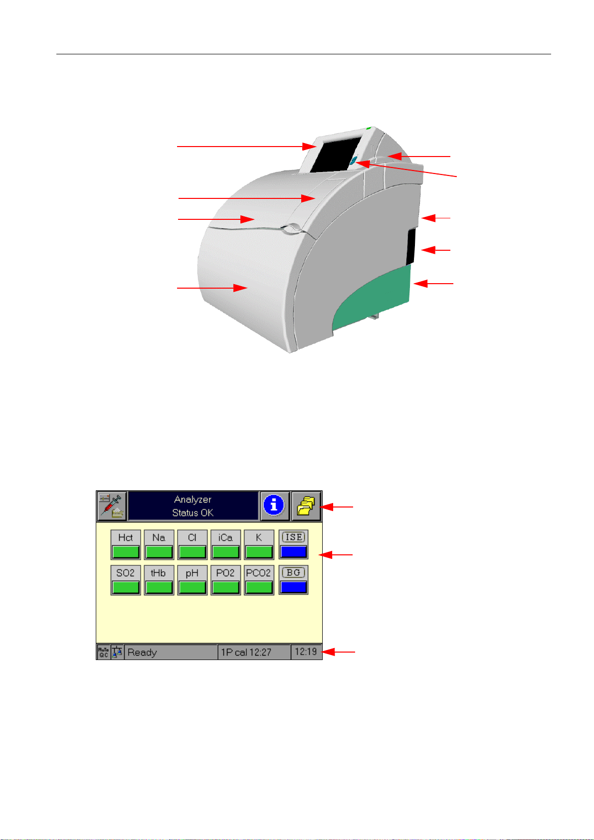
2System description
screen
flap
2 System description
printer cover
contrast setting
instrument cover
bottle compartment cover
Fig. 1
2.1 Screen
All information (results, error messages, warnings, etc.) is displayed on the screen. The
screen consists of a 5.7" colour LCD that is covered with a touch-sensitive film.
2.1.1 Screen arrangement
The Roche OMNI C screen is divided into three main areas:
reverse side
power pack /
mains switch
unlocking knob
for the AutoQC
module
header line
operating mode area
status line
Fig. 2
This screen division applies to all areas of the Roche OMNI C software. The header and status lines are always available in the same division, the operating mode area depicts the status
of the currently active operating mode and serves the interaction of the operating modes
with the user.
Reference Manual, Roche OMNI C, Rev. 5.0, Juli 2003 2-1
Page 14
2 System description
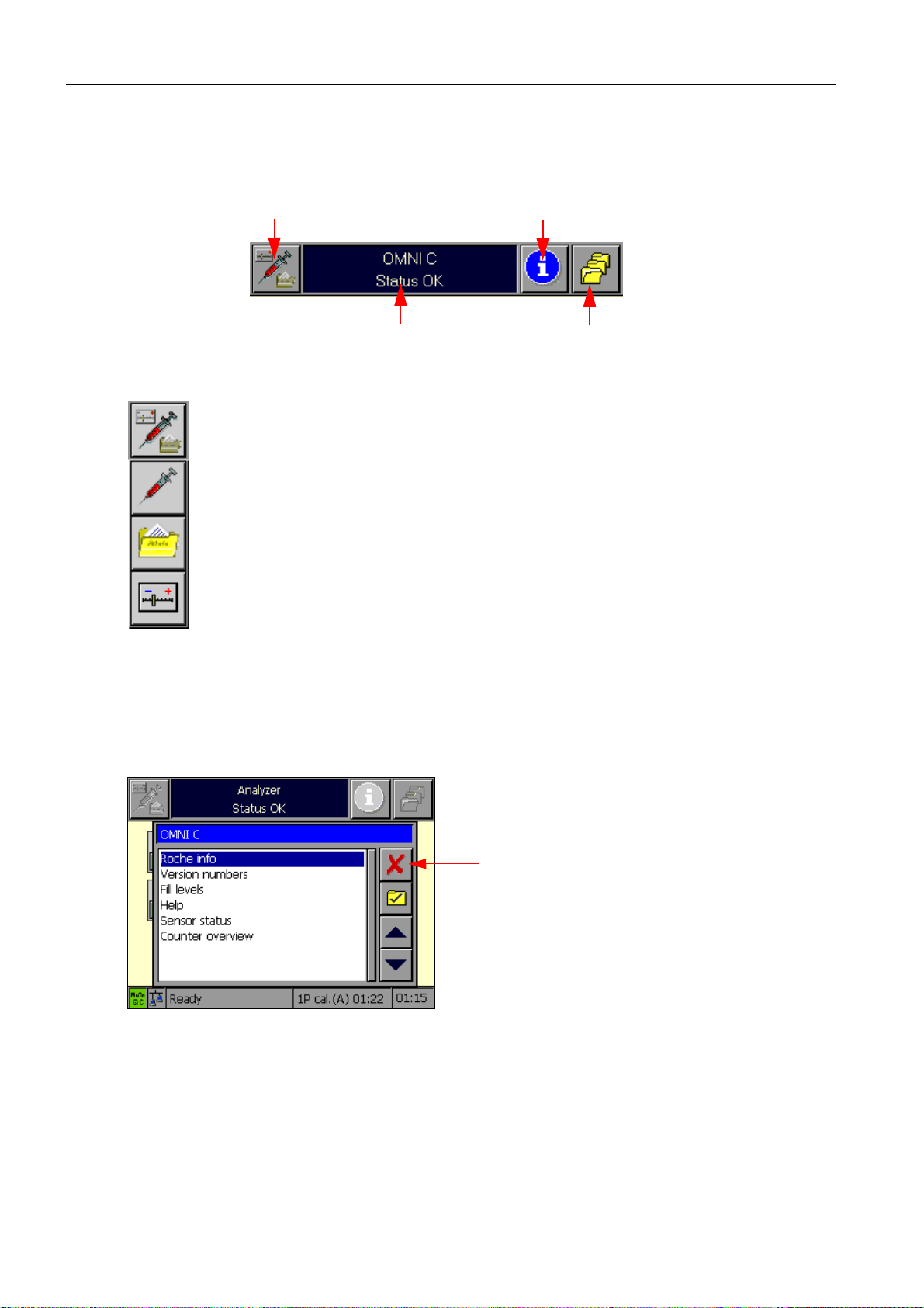
2.1.2 Header line
The header line contains the following elements:
operating mode selection button
general information window
Fig. 3
The operating mode selection button enables switching between the individual
operating modes: Analyzer, Database, and Setup.
Pressing one of these buttons initiates a switch to the desired operating mode.
The menu times out after 5 seconds. In other words, when the user does not take
any action, the menu disappears automatically after this length of time. Pressing
the operating mode selection button again while the menu is visible closes the
menu. Upon selection of an operating mode, the display switches to the corresponding side of the screen.
info button
button for "More functions"
The info button activates the Info operating mode. The Info operating mode has a special
status because it is virtually superimposed on top of the other operating modes. The Info
operating mode contains information on everything that could be associated with the
instrument, specifically all status information (fill levels, electrodes, log entries), user information, and on-line help. Upon exit, the Info operating mode terminates completely.
Cancel
Fig. 4
2-2
Reference Manual, Roche OMNI C, Rev. 5.0, Juli 2003
Page 15

2 System description
The button calls up a window with which the following functions may be activated:
Fig. 5
The keys are used for navigation through various operating modes or to functions in the
current view. The "Cancel" button or a timeout closes the window without action.
The currently active operating mode uses the general information window to display navigation notes and/or detailed information about the displayed window.
2.1.3 Parallel operating modes
Analyzer
Database
Setup
Information,
Help
Fig. 6
For more detailed information about the operating modes, please see the respective chapters
in this Reference Manual or in the Instructions for Use.
More
functions
Reference Manual, Roche OMNI C, Rev. 5.0, Juli 2003 2-3
Page 16
2 System description
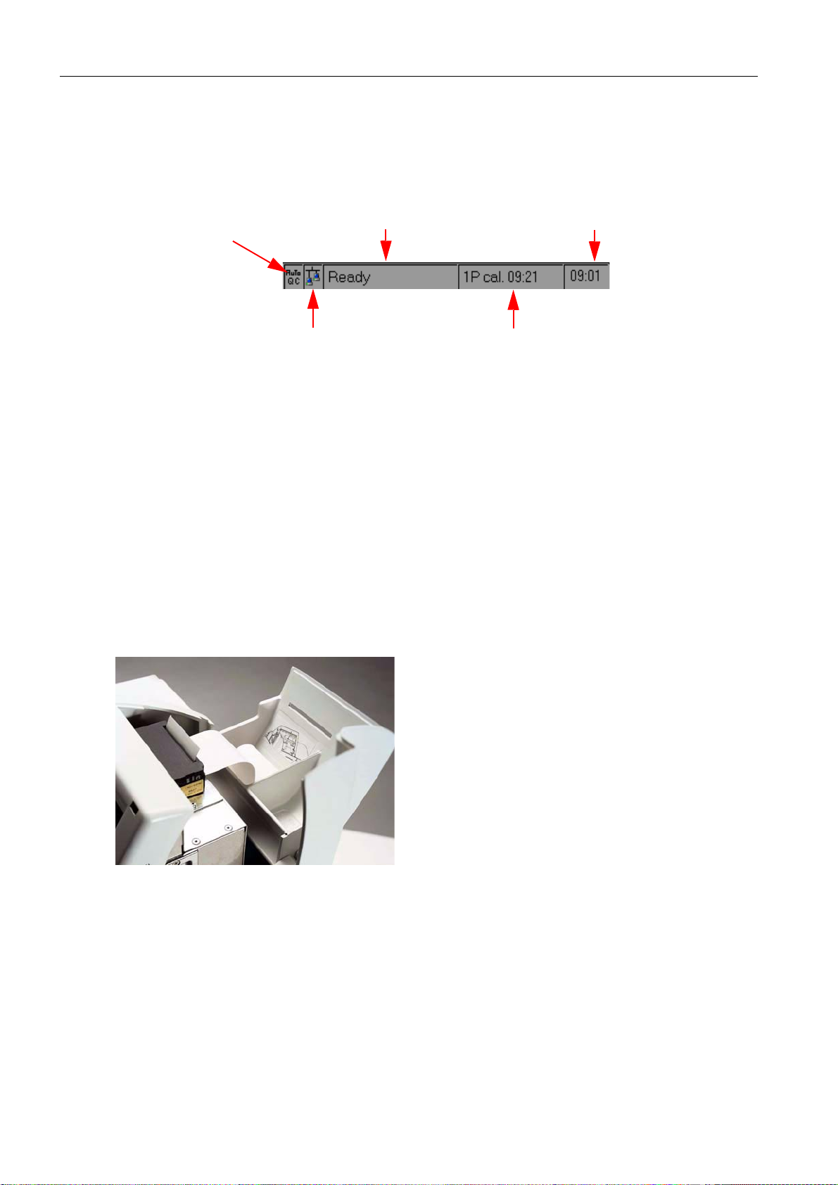
2.1.4 Status line
The status line permanently displays information about the Analyzer operating mode. The
following information is displayed :
AutoQC logo
(option available)
Fig. 7
1)
Logo background: green: activated and ready
2)
Logo background: green: connected
2.2 Printer
1)
remote control logo
actual analyzer status current time
red: activated, not ready
gray: not installed
gray: not connected
2)
time and type of the next action
that will interrupt the "Ready" status
Low-noise 2" thermal printer with integrated paper cutter.
Fig. 8
TIP: The printer paper is heat sensitive on one side only.
Please be certain that you insert the thermal paper correctly! Observe the instructions on the
label on the inside of the printer cover.
2-4
Reference Manual, Roche OMNI C, Rev. 5.0, Juli 2003
Page 17
2.3 Measuring chamber
The measuring chamber consists of the following components
• Electrical ground contact: grounds electrode amplifier's electrical currents.
• tHb/SO
• Val ve V 3, V5 : these valves serve to control the transport of fluid.
• Sample sensors SS1, SS2: these two sensors are located under the black sample sensor
covering plate. They detect the operating fluids and the sample.
• Tubi ng
• Measuring chamber trough: this is held at 37 °C. The electrodes are pushed through the
spring contacts against the retainers into the socket.
• Measuring chamber cover: it is held at 37 °C, contains the electrode window and the
switching magnet for the measuring chamber cover sensor.
• Contact bank: the contact bank contains the replaceable spring contacts for the elec-
trodes and the cover sensor. The electrode amplifiers are located behind the contact
bank.
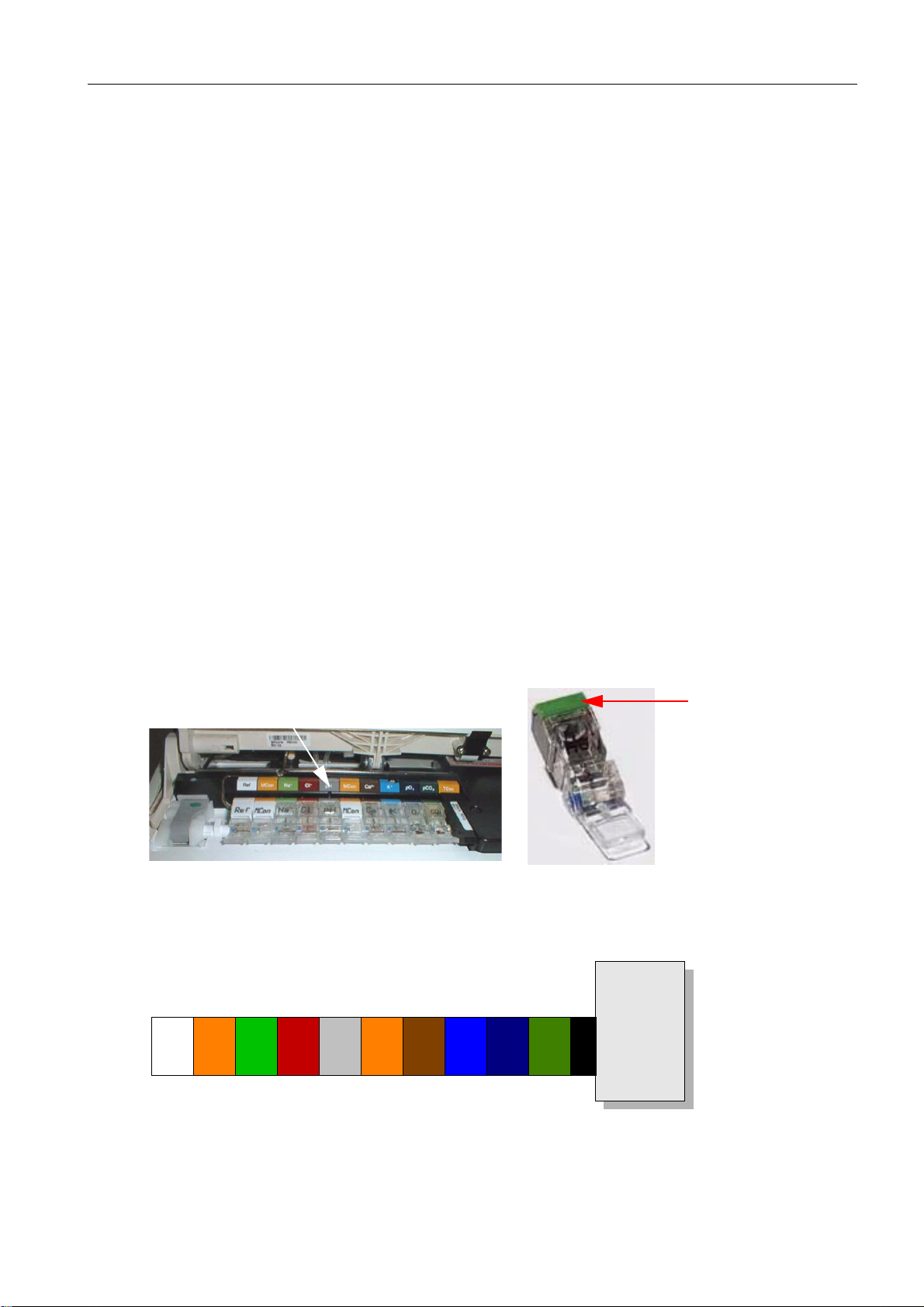
A colour-coded strip is located above the contact bank and is used to identify the electrodes.
• Left retainer: serves to secure the electrodes as well as the tubes used with the reference
electrode.
• Locking lever: movable part of the left retainer.
module: see section 2.3.2!
2
2 System description
2.3.1 Electrodes
The correct positions of the various electrodes are easy to determine by the colours on their
contact caps and/or by their labelling (see "Contact bank").
contact bank
Fig. 9
Colours of the electrode contact caps:
MCon pH MCon K
Ref
Na+Cl
contact cap
tHb / SO
-
Ca
+
2+
PO
PCO
2
TCon
2
2
Fig. 10
Reference Manual, Roche OMNI C, Rev. 5.0, Juli 2003 2-5
Page 18
2 System description
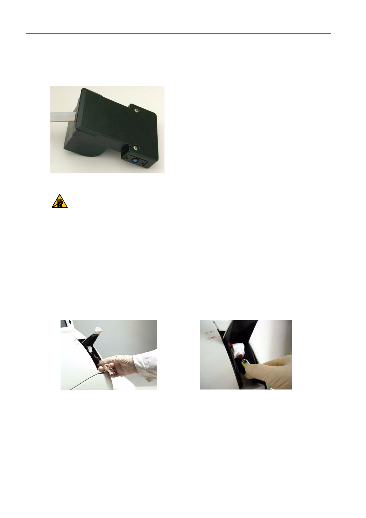
2.3.2 tHb/SO2 module
The tHb/SO2 module is an optical sensor module for determining the levels of total hemoglobin (tHb) and oxygen saturation (SO
Fig. 11
The complete module is sealed and calibrated at the factory ("Factory setting") and
may be exchanged only as a complete unit.
) in whole blood.
2
Never open the module!
2.4 Sample port module
The sample port module consists of the flap, the fill port holder (including fill port), the
needle and the sample drip tray.
Flap
When opening the flap, notice two definitive locking positions:
• Flap position 1 (half opened) – syringe mode—for syringes and ampoules
2-6
Fig. 12
syringe
ampoule
Reference Manual, Roche OMNI C, Rev. 5.0, Juli 2003
Page 19
2 System description
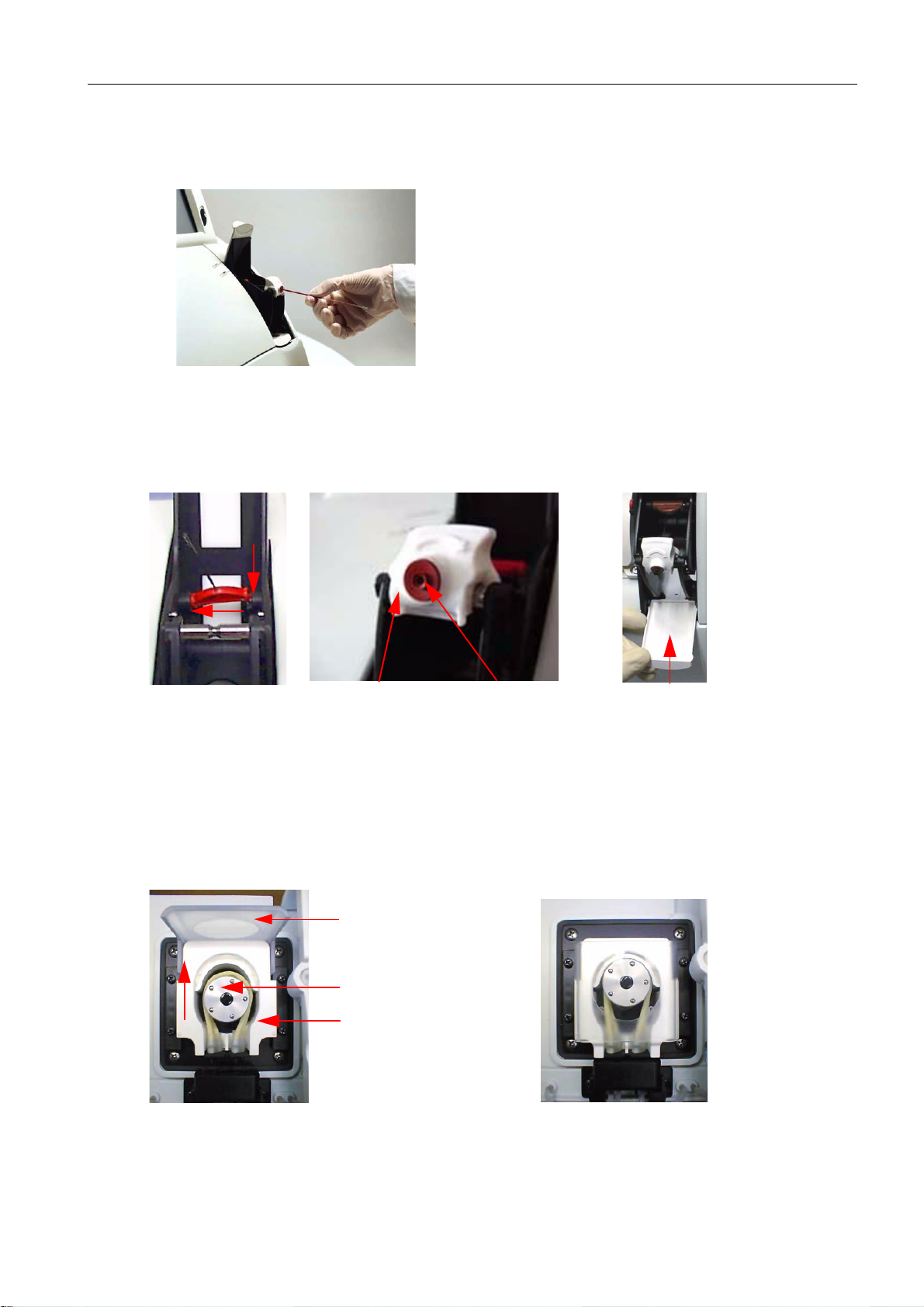
• Flap position 2 (completely opened) – Capillary mode—for capillaries and
Roche MICROSAMPLERS
Fig. 13
Needle, fill port holder with fill port and sample drip tray
suction tube fill port holder and fill port sample drip tray
Fig. 14
2.5 Pump
The peristaltic pump transports the sample and the operating fluids inside the instrument.
pump open
Fig. 15
tension lever
pump head
linear clamp
pump closed
Reference Manual, Roche OMNI C, Rev. 5.0, Juli 2003 2-7
Page 20
2 System description
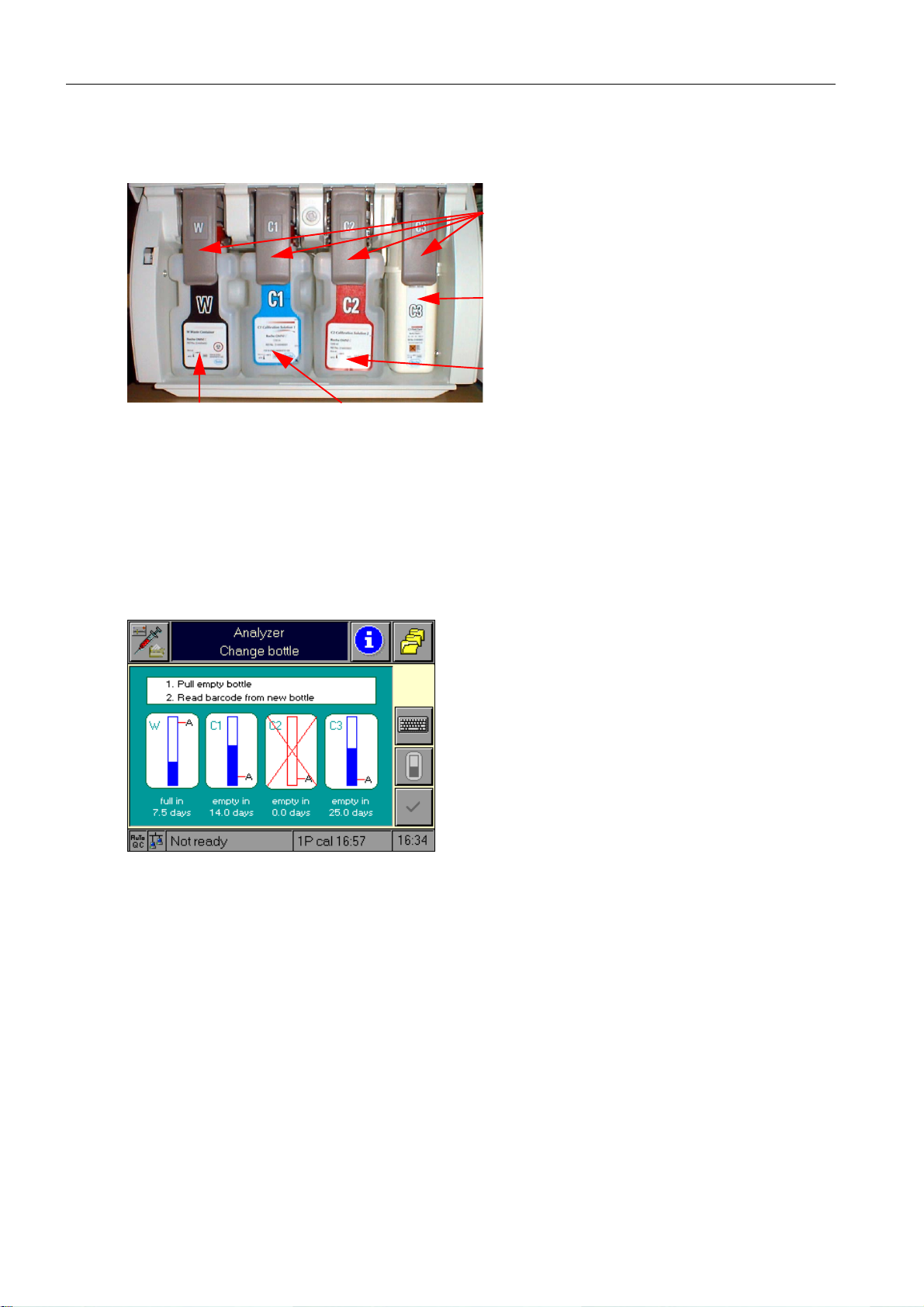
2.6 Bottle compartment
Docking mechanism
C3 fluid pack
C2 calibration solution 2
W waste container
Fig. 16
C1 calibration solution 1
2.6.1 Bottle compartment cover
A microswitch detects the status of the cover (open / closed).
The following image appears when the cover is opened (bottle exchange):
Fig. 17
2.7 Reverse side
See Instructions for Use, chapter 1 "Introduction"!
2-8
Reference Manual, Roche OMNI C, Rev. 5.0, Juli 2003
Page 21

2.8 Power rating1- power supply
2 System description
Comments /
operating
conditions
Test No.
VoltageVFrequencyHzCurrentAPower in WPower in
VA
1 90 50 2.01 145 174 warm-up
2 100 50 1.78 145 175 warm-up
3 240 50 0.78 133 188 warm-up
4 264 50 0.72 137 191 warm-up
5 90 60 2.18 148 196 warm-up
6 100 60 1.95 142 194 warm-up
7 120 60 1.67 138 200 warm-up
8 132 60 1.54 139 203 warm-up
9 240 60 0.97 133 233 warm-up
10 264 60 0.89 131 235 warm-up
11 240 50 0.29 44 70 Standby / normal
operating conditi-
ons
2.9 Instrument cover
The instrument cover provides mechanical protection for the measuring chamber, pump
and valves. The cover is removable, but must remain closed while the unit is in operation.
1
Taken from the report of VDE: Testing and Certification Institute
Reference Manual, Roche OMNI C, Rev. 5.0, Juli 2003 2-9
Page 22
2 System description
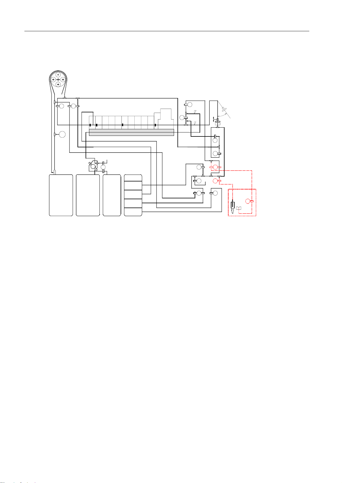
2.10 Tubing system
Peristaltic Pump
Air
V6 V7
Ref MConMCon
Pa
FMS
W
Waste Solution C1
V1
Measuring Chamber
Na Cl pH Ca K
MCMMCCMCO
Air
V2
O2 Zero Point
Solution
C2C1
Conditioning
Solution
Solution C2
Fig. 18
V1 ........ C1/C2 mixing valve
V2 ........ Air mixing valve
V3 ........ MC wash valve
V4 ........ MC bypass valve
V5 ........ Wash needle
V6 ........ MC out
V7 ........ Conditioner
V8 ........ Reference solution
V9 ........ Ventilation
V10 ...... Cleaning solution
V11 ...... Zero point solution
V14 ...... Bypass
C3
Cleaning
Solution
Reference
Solution
O2 CO2
V5
SS2
TCon
tHb/sO2
MCI
V3
SS1
V11
Air
V9
Air
V10 V8
Needle
V4
V14
V13
V12
AutoQC
V17
2-10
SS1, SS2....... Sample sensors
If the AutoQC module has been installed:
V12 ...... AQC valve
V13 ...... AQC wash valve
V17 ...... AQC wash valve II
Reference Manual, Roche OMNI C, Rev. 5.0, Juli 2003
Page 23

3 Operating modes
3 Operating modes
3.1 Analyzer ............................................................................................................................ 3-1
3.1.1 "Ready" screen...............................................................................................................................................3-1
Parameter – depiction and buttons ................................................................. 3-1
Mandatory input ............................................................................................ 3-2
Password ........................................................................................................ 3-2
3.1.2 System ...............................................................................................................................................................3-3
Wash and clean .............................................................................................. 3-4
Tools .............................................................................................................. 3-6
Test .............................................................................................................. 3-13
Calibrations ................................................................................................. 3-26
3.1.3 Quick access ................................................................................................................................................ 3-26
3.1.4 QC measurement........................................................................................................................................ 3-26
3.2 Setup ................................................................................................................................ 3-27
3.2.1 Parameter ...................................................................................................................................................... 3-27
Miscellaneous settings .................................................................................. 3-28
Reference / critical ranges ............................................................................. 3-31
Correlations ................................................................................................. 3-32
3.2.2 Times & intervals ........................................................................................................................................ 3-33
Date and time ............................................................................................... 3-33
Calibration intervals ..................................................................................... 3-34
QC times ...................................................................................................... 3-34
Economy mode ............................................................................................. 3-34
Timeouts ...................................................................................................... 3-38
3.2.3 QC material................................................................................................................................................... 3-39
Set ranges ..................................................................................................... 3-39
AutoQC mat setup ........................................................................................ 3-39
3.2.4 Interfaces....................................................................................................................................................... 3-40
Network ....................................................................................................... 3-40
ASTM communication .................................................................................. 3-42
COM 1 ......................................................................................................... 3-42
COM 2 ......................................................................................................... 3-44
3.2.5 Displays & reports ...................................................................................................................................... 3-45
Measuring data ............................................................................................. 3-46
Parameter: display ranges ............................................................................. 3-54
QC ............................................................................................................... 3-54
Calibration ................................................................................................... 3-54
Patient database ........................................................................................... 3-54
Instrument data ............................................................................................ 3-55
Reference Manual, Roche OMNI C, Rev. 5.0, Juli 2003 3-I
Page 24

3 Operating modes
3.2.6 Instrument ..................................................................................................................................................... 3-56
Language ...................................................................................................... 3-57
Roche info .................................................................................................... 3-58
Brightness level ............................................................................................. 3-59
Speaker ......................................................................................................... 3-59
Automatic patient ID .................................................................................... 3-60
Other units ................................................................................................... 3-60
Clinic info .................................................................................................... 3-61
Cleaning counter .......................................................................................... 3-61
AutoQC ........................................................................................................ 3-62
Ext. patient query ......................................................................................... 3-62
3.2.7 Password........................................................................................................................................................ 3-63
Security level ................................................................................................ 3-63
User management ......................................................................................... 3-63
Group administration ................................................................................... 3-64
3.2.8 Service area (password protected)...................................................................................................... 3-64
3.3 Database ......................................................................................................................... 3-65
3.3.1 Patient data................................................................................................................................................... 3-65
3.3.2 Measuring data ........................................................................................................................................... 3-66
3.3.3 Calibration data ........................................................................................................................................... 3-67
3.3.4 QC data .......................................................................................................................................................... 3-67
3.3.5 Instrument data ........................................................................................................................................... 3-68
3.3.6 Data export ................................................................................................................................................... 3-69
3.3.7 Delete data....................................................................................................................................................3-70
3-II
Reference Manual, Roche OMNI C, Rev. 5.0, Juli 2003
Page 25
3 Operating modes
The Roche OMNI C is a combined bloodgas, electrolyte, and tHb/SO2 analyzer. It is possible
to complete database procedures or to make adjustments simultaneously during measurement or calibration.
The individual, mutually independent operating modes are defined as follows:
a) Analyzer: measuring, QC, system, calibration, quick access
b) Setup: instrument settings
c) Database: contains data on patients, measuring, calibration, QC, and the instrument
d) Info: Roche info, version numbers, fill levels, help, sensor status
3.1 Analyzer
The Analyzer operating mode has a special status among the operating modes.
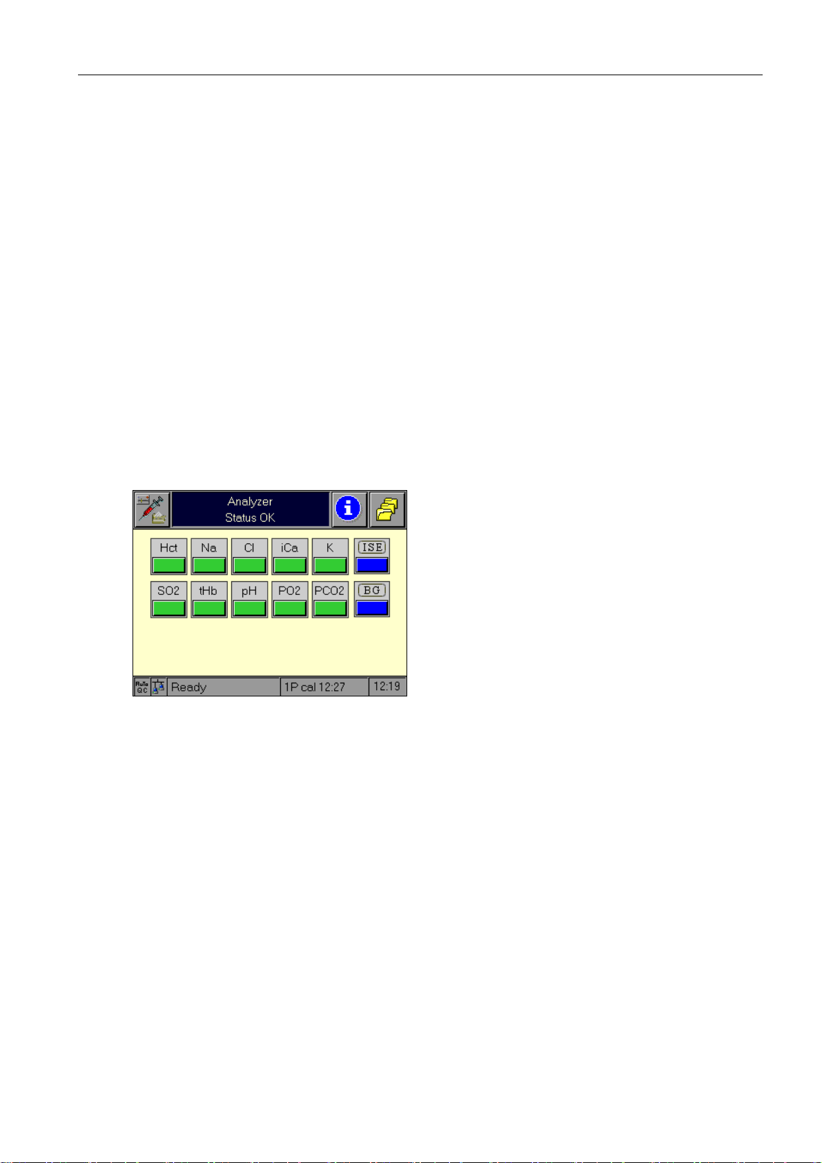
3.1.1 "Ready" screen
3 Operating modes
The Ready screen is the central starting point for all operations.
Fig. 1
Parameter – depiction and buttons
For a description of the parameter depiction and buttons, please see Instructions for Use,
chapter 1, "Introduction."
Reference Manual, Roche OMNI C, Rev. 5.0, Juli 2003 3-1
Page 26
3 Operating modes
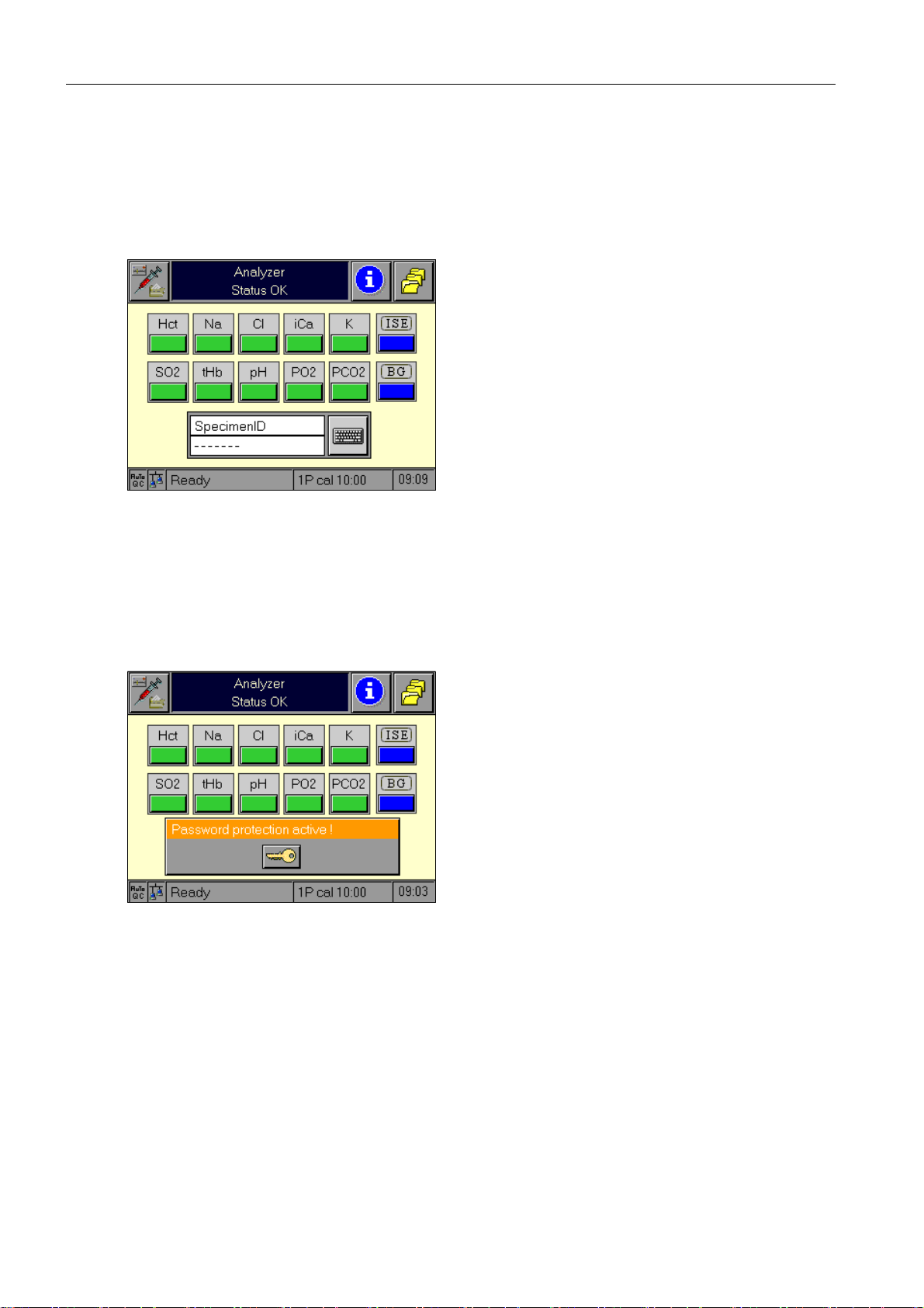
Mandatory input
Furthermore, the "Ready" screen can be modified by the activation of a "Mandatory input"
field. If this function is activated in the "Setup" mode, a measurement can be started only
when the entry has been completed.
In the following example, the access code has been defined as a mandatory entry.
Fig. 2
Password
If the measurement is equipped with password protection, the "Ready" screen is covered by
the password window but the parameter section remains visible (parameter information).
Fig. 3
3-2
Reference Manual, Roche OMNI C, Rev. 5.0, Juli 2003
Page 27
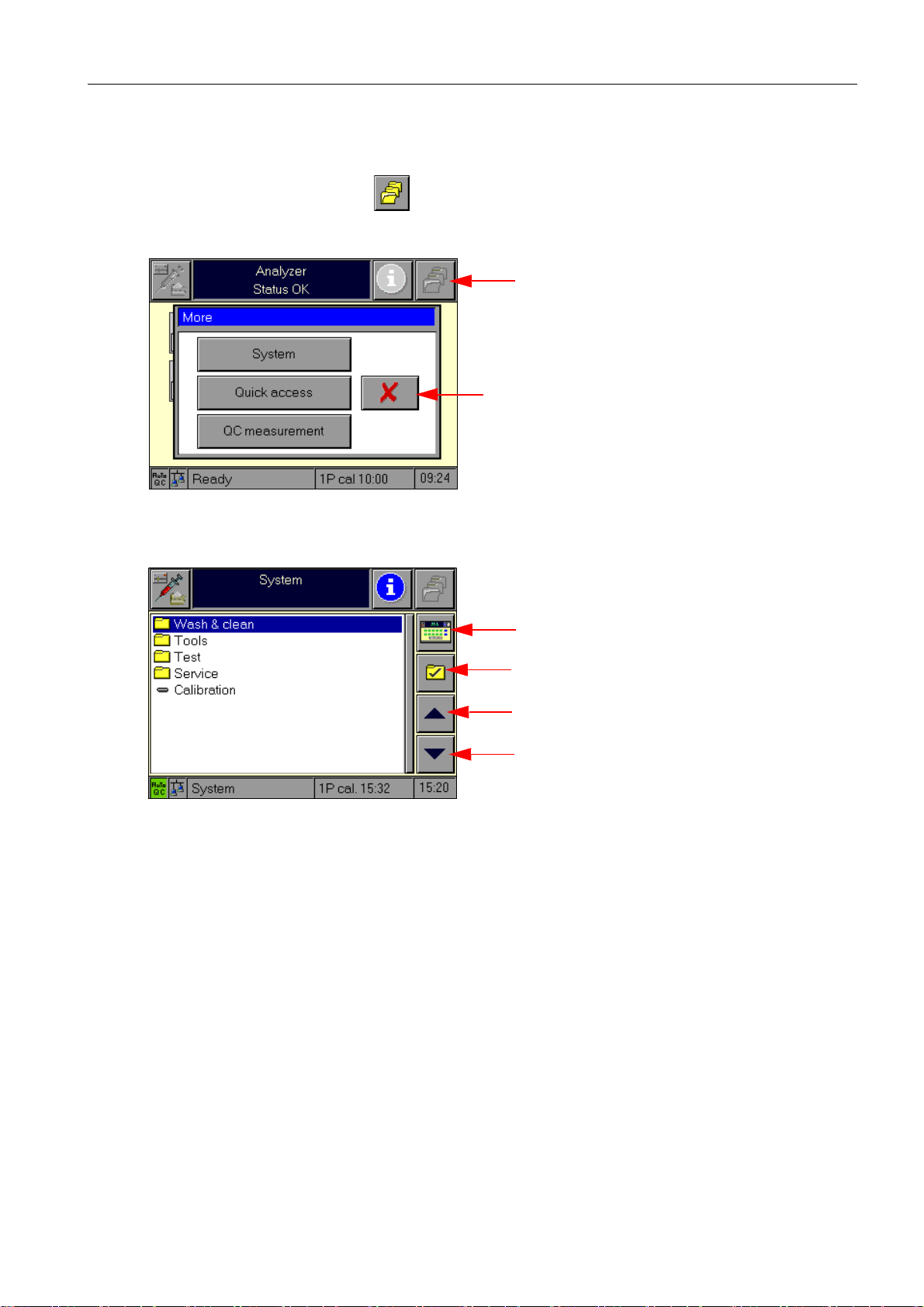
3.1.2 System
The system section can be reached directly and only from the "Ready" screen.
This occurs by pressing the button.
This button calls up a window with which the following functions may be activated:
Fig. 4
3 Operating modes
more functions
pressing this button or a defined timeout closes
the window without action
The following main menus are available:
Fig. 5
highest level of the Analyzer mode
select / deactivate
move one line up
move one line down
Reference Manual, Roche OMNI C, Rev. 5.0, Juli 2003 3-3
Page 28
3 Operating modes
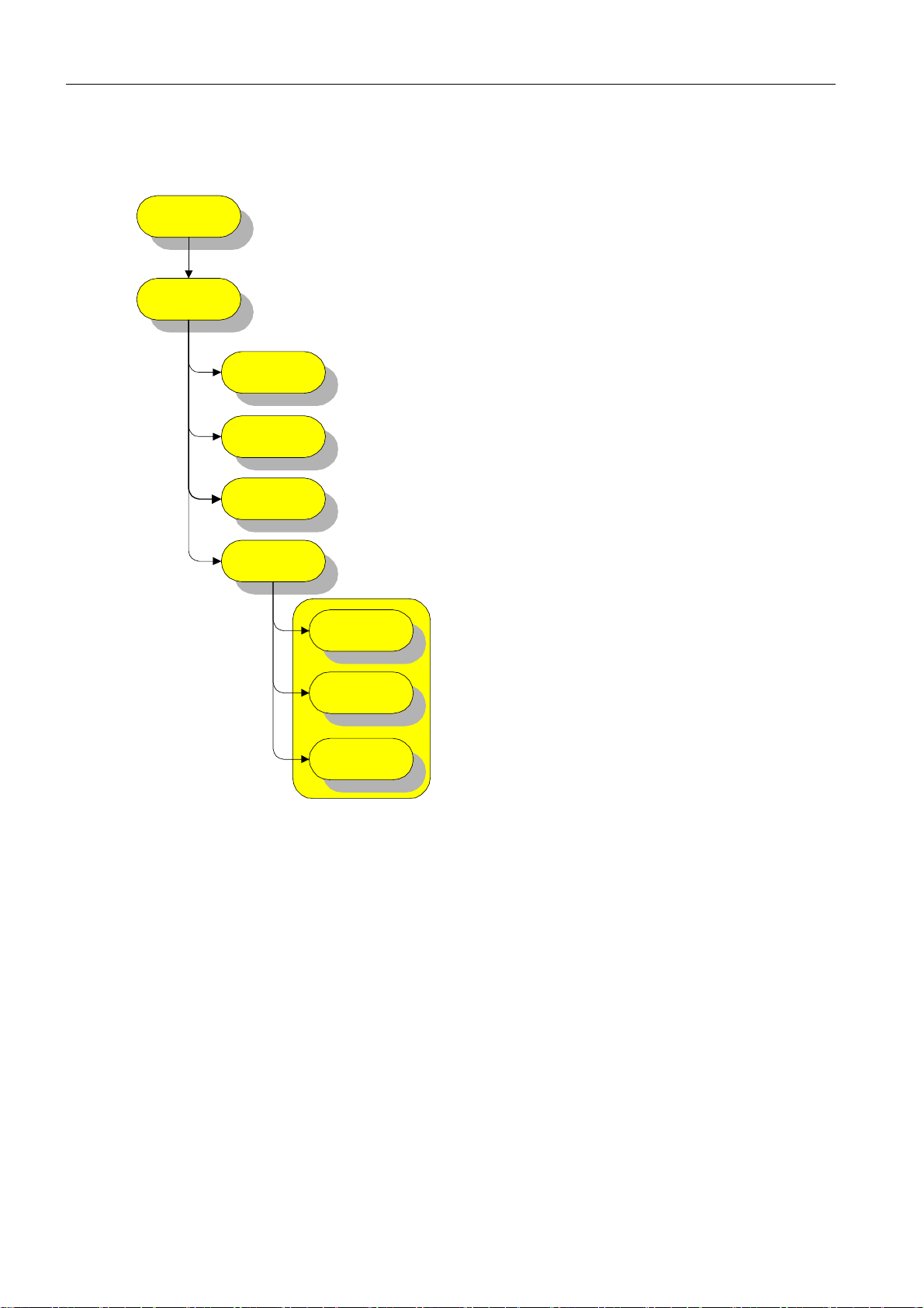
Wash and clean
System
Wash & Clean
Clean screen
Decont. sample
port module
Decontaminate
all tubes
Automatic
routines
Wash sample
path
Wash AutoQC
Internal cleaning
of sample path
Fig. 6
Clean screen
Upon entry into this function, the screen clears (white) and the touch screen deactivates for
30 seconds. A counter on the screen indicates the remaining number of seconds.
After expiration of the 30 seconds, the next highest level menu appears again. Please see
chapter "Maintenance" in the Instructions for Use for instructions on this cleaning procedure.
3-4
Decontaminate sample port module
This function assists in the decontamination of the sample port module, which consists of
flap, needle, filling port holder, filling port, and wash plate.
Please see chapter "Maintenance" in the Instructions for Use for instructions on this cleaning procedure.
Reference Manual, Roche OMNI C, Rev. 5.0, Juli 2003
Page 29

3 Operating modes
Decontaminate all tubes
Follow the instructions on the screen. Confirm every step with !
The shutdown kit gives instructions on decontaminating all tubing.
For a description, please see Instructions for Use, chapter 6, "Maintenance",
section "Decontamination – Tubing paths."
Automatic routines
Wash sample path
This function washes out the sample path. It is not possible to interrupt this routine.
Wash AutoQC (option)
This function washes the optional AutoQC module if it is installed. It is possible to interrupt
this sequence.
Internal cleaning of sample path
This function cleans the sample path. It is not possible to interrupt this sequence.
Reference Manual, Roche OMNI C, Rev. 5.0, Juli 2003 3-5
Page 30
3 Operating modes
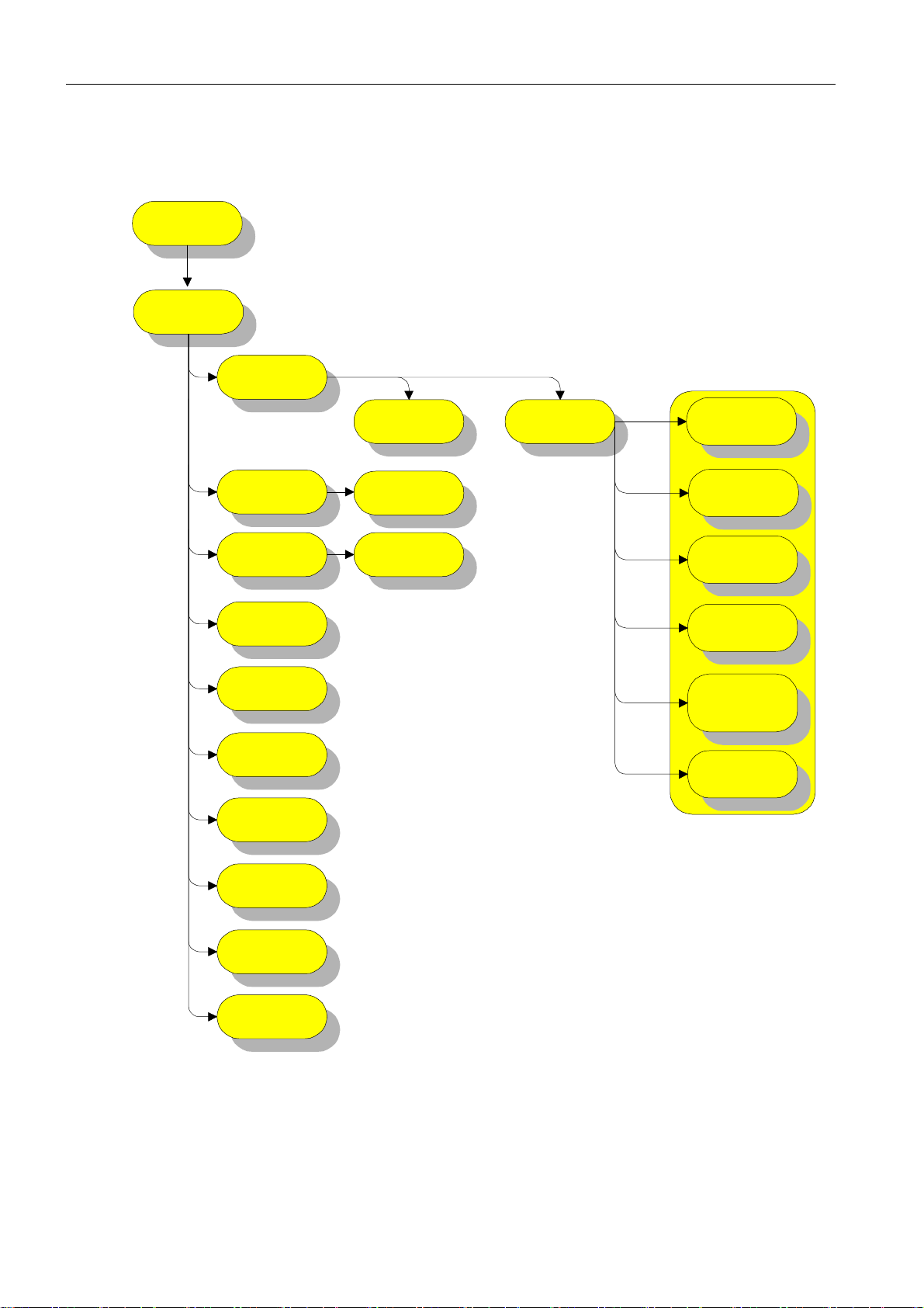
Tools
System
Tools
Fluid actions
Tubing
exchange
Software
communication
Manual
economy mode
Software
shutdown
Shutdown
Installation
Conditioning
cycle
Replace PP
tubing
Software update
Auto
preparation
routines
Fill reference
electrode
Prepare
Calibration
Solution C1
Prepare
Calibration
Solution C2
Prepare
conditioning
solution
Prepare O2 zero
solutiom
Prepare
cleaning
solution
3-6
Export log data
Maintenance
PCMCIA-card
Fig. 7
Reference Manual, Roche OMNI C, Rev. 5.0, Juli 2003
Page 31

3 Operating modes
Fluid actions
Conditioning cycle
This function conditions the unit. It starts a sequence as with other automatic suction routines. The sequence may not be interrupted and displays a message in the event of a fault.
Auto preparation routines
Fill reference electrode
This function suctions the reference solution to the reference sensor. The sequence may not
be interrupted and displays a message in the event of a fault.
Prepare Calibration Solution C1
This function provides upward suction of the C1 calibration solution 1. The sequence may
not be interrupted and displays a message in the event of a fault.
Prepare Calibration Solution C2
This function provides upward suction of the C2 calibration solution 2. The sequence may
not be interrupted and displays a message in the event of a fault.
Prepare conditioning solution
This function provides upward suction of the conditioning solution. The sequence may not
be interrupted and displays a message in the event of a fault.
Prepare PO2 zero solution
This function provides upward suction of the PO2 zero solution. The sequence may not be
interrupted and displays a message in the event of a fault.
Prepare cleaning solution
This function provides upward suction of the cleaning solution. The sequence may not be
interrupted and displays a message in the event of a fault.
Tubing exchange
PP tubing exchange
This function is used to perform the exchange of the peristaltic pump tubing.
Reference Manual, Roche OMNI C, Rev. 5.0, Juli 2003 3-7
Page 32

3 Operating modes
Software communication
Software update
Use this function to load a new program. The required parameters may also be entered. The
following parameters are currently available:
Source:FTP, PCMCIA
Update file:update information file
Source path:path to the location of the update file
Host address:IP address of the remote computer if FTP was selected as the source
Start the execution with the button.
Manual economy mode
Use this function to manually activate a pause mode if you do not intend to use the Roche
OMNI C for an extended period of time.
Fig. 8
The units uses smaller quantities of solutions during this time. A system maintenance process ensures that the electrodes remain optimally conditioned, however.
Software shutdown
This function brings the instrument to shutdown status.
It is necessary to follow the proper shutdown procedure because a sudden shutdown can
lead to the loss of data!
A message appears on the screen that instructs the user to switch off or restart the instrument.
3-8
Reference Manual, Roche OMNI C, Rev. 5.0, Juli 2003
Page 33

Fig. 9
Shutdown
This function enables program-supported shutdown of the instrument.
3 Operating modes
Each of the actions that should be performed are listed in the listbox as the final entry. Confirm the manually completed actions.
If any of the actions are to be performed by the instrument, this will be indicated by the
blocking of the confirmation button and activation of the "Start action" button. The next
step to be performed will be automatically entered into the listbox as the final line. Following completion of instrument actions, the status "OK" or "not OK" is displayed at the end
of each line.
For information on the shutdown procedure, please see chapter 1 "Introduction", section
"Shutdown" in the Instructions for Use!
TIP: After successfully shutting down the instrument, it will be in the "System stop" mode (shut
down). This can be reversed only by a renewed startup procedure.
Installation
This routine enables program-supported startup of an instrument. Each of the actions that
should be performed are listed in the listbox as the final entry. Confirm the manually completed actions.
If any of the actions are to be performed by the instrument, this will be indicated by the
blocking of the confirmation button and activation of the "Start action" button. The next
step to be performed will be automatically entered into the listbox as the final line. Following completion of instrument actions, the status "OK" or "not OK" is displayed at the end
of each line.
Reference Manual, Roche OMNI C, Rev. 5.0, Juli 2003 3-9
Page 34

3 Operating modes
Fig. 10
For information on the startup procedure, please see chapter 1 "Introduction", section
"Installation" in the Instructions for Use!
TIP: If an error appears following the start of the action "Begin installation routine" (final step
of installation), a system stop is displayed but the instrument is regarded as having been
brought into operation.
Export log data
You can use this function to export log data.
TIP: Selection of all or single log data is possible.
Fig. 11
Use the "line up/down" buttons to select the log data. Then press the key and select
where you wish to store the log files.
Only available destinations, such as FTP and PCMCIA, are indicated. Confirm here, all log
files are copied. With the PCMCIA card, it is additionally checked whether enough memory
is available.
The log files are copied to a fixed "Export" path with the serial number at the front. With
the PCMCIA card, an "Export" directory is automatically created, with an FTP transfer, it
must already be available.
3-10
Reference Manual, Roche OMNI C, Rev. 5.0, Juli 2003
Page 35

If log files are available, they can be deleted using the button.
3 Operating modes
If no log file is available, a corresponding
error message is issued in the file list
and the and buttons are deactivated.
Maintenance
Use this function to call up an overview of all maintenance entries and their status.
Fig. 12
The following maintenance is entered by default and can be neither deactivated nor
renamed:
• Annual maintenance
• PP tubing exchange
• Decontaminate bottle compartment
• Decontaminate sample port module
• Decontaminate screen
• Exchange fill port holder
If a maintenance is planned, it is displayed in "red" in the list.
Use to mark the maintenance as performed. The next cycle time is calculated.
Use to enter the maintenance as "skipped" in the device database.
Use to create a separate entry that is saved in the device database.
Reference Manual, Roche OMNI C, Rev. 5.0, Juli 2003 3-11
Page 36

3 Operating modes
PCMCIA card
Use this function to create a defined PCMCIA card.
Fig. 13
Status:The current status of the PCMCIA card is displayed. The properties (application purpose) of the card are marked with a green check mark.
Use the button to change the properties of the card.
TIP: If a card is not assigned, no setting can be performed.
Serial number of the card: The serial number of the PCMCIA card is displayed.
Free memory: Call up information about the assignment status of the card.
Remove PCMCIA card: Use this function to remove the card.
Remove the card only by using the "Remove PCMCIA card" menu item, since a sudden
removal can lead to data loss!
Assign card: The card used is assigned to the device.
Create export card: Create an export card on which database files and log files can
not be stored.
Initialize card: Delete all data on the card.
3-12
Reference Manual, Roche OMNI C, Rev. 5.0, Juli 2003
Page 37

Test
3 Operating modes
MBX boar d
AutoQC
Baro sensor
control
Temperature
sensors
Monitoring
position test
Peristaltic pump
sensor
Waste Container
Contact paths
Flash file
PCMCIA card
system
Barcode
System
Test
Valves &
aggregates
Valves
Sample sensor s
Control sensors
Screen Touch screen Printer
sensors
PC components
Measuring
Fig. 14
Reference Manual, Roche OMNI C, Rev. 5.0, Juli 2003 3-13
Page 38

3 Operating modes
Valves and aggregates
Valves
This test checks the switching function of all valves. To perform a check, a single valve may
be switched or 10 separate switches (5 times open/close or close/open) may be performed
automatically.
overview of valve positions in the instrument
depiction of valve status
individually switch a valve
automatic switching procedures
Fig. 15
In addition, the status of each valve is displayed schematically (for example: V1).
Fig. 16
Peristaltic pump
This test checks the peristaltic pump in four defined speeds.
3-14
Only suction is possible because reverse rotation of the pump would remove fluid from
the W waste container!
In addition, the following is displayed:
• pump volume in µl per revolution
• the FMS volumes in µl
Service technicians and certain users are able to start a calibration sequence for the pump.
They are then also able to re-establish the FMS volumes and save these as new settings.
Reference Manual, Roche OMNI C, Rev. 5.0, Juli 2003
Page 39

Press the key and follow the instructions on the screen.
Fig. 17
AutoQC position test
This function tests the positions of the ampoule block.
3 Operating modes
The following positions are possible:
Fig. 18
Position:
"Home position": the needle is positioned over the wash port
"Service position": NOTE: remove the ampoule block before going to the service posi-
tion.
The carriage moves to position 106.
"Go to position": goes to any ampoule position from 1 to 120.
Needle:
"End position":the carriage with the needle moves upwards to the end position.
"Aspiration position": the carriage with the needle moves downwards to the aspira-
tion position.
CAUTION: danger of injury from moving parts!
Reference Manual, Roche OMNI C, Rev. 5.0, Juli 2003 3-15
Page 40

3 Operating modes
Control sensors
Sample sensors
This test completes a check of the optical sample sensors 1 and 2.
The following is also displayed:
• calibration value of the sensor
• actual measurement value in mV
• actual measurement value in % based on the calibration value
• evaluation of the actual measurement value or notification that plausibility test is not
acceptable
Service technicians and certain users are able to start a calibration sequence for the sample
sensors. This sequence determines the calibration value for the specific sensor and adopts
this as the new setting.
Press the button and follow the instructions on the screen.
Fig. 19
Contact paths
The actual entered conductivity values are displayed (in mV) for the specified contact paths
with the fluid available in the sample channel.
Fig. 20
3-16
Reference Manual, Roche OMNI C, Rev. 5.0, Juli 2003
Page 41

3 Operating modes
Waste container sensor
Display of the actual values for the waste water sensor.
• actual value: signal in mV
• slope in mV/mbar
• zero point in mV (determined in advance during the measurement)
• fill level in %
• fill level in mm (last measured value, manually or by a system calibration)
Fig. 21
Use the button to determine the current fill level in mm (see Fig. 20).
Fig. 22
Monitoring sensors
This test window displays the status of all monitoring sensors.
These are:
• Sample port module
status: closed, syringe position, capillary position
• MC cover
status: open, closed
• Bottle compartment
Reference Manual, Roche OMNI C, Rev. 5.0, Juli 2003 3-17
Page 42

3 Operating modes
status: open, closed
• C3 docking mechanism
status: open, closed
• W waste container
status: open, closed
• AutoQC cover
status: open, closed
Fig. 23
Temperature control
Actual temperature display.
Fig. 24
Limit values are established for the following boards:
with AutoQC
3-18
MBX board: 1 - 55 °C
Reference Manual, Roche OMNI C, Rev. 5.0, Juli 2003
Page 43

3 Operating modes
Baro sensor
Display of the actual values for the baro sensor.
These are:
• actual value in mV
• calibration point in mV
• slope in mV/bar
• calculated air pressure in the unit according to adjustments
Service technicians and certain users are able to start a calibration sequence for the baro
sensor. This sequence determines the calibration value for the baro sensor and adopts this
as the new setting.
Press the button and follow the instructions on the screen.
Fig. 25
PC components
Screen
Fig. 26
The "Test" function helps to check the functionality of the screen.
These are:
• checking for failure of individual picture elements
• checking for failure of colours
Reference Manual, Roche OMNI C, Rev. 5.0, Juli 2003 3-19
Page 44

3 Operating modes
• checking the illumination lamps (on/off/?)
The following test procedure will be executed:
1. Black screen (for 5 seconds)
2. White screen (for 5 seconds)
3. Display of complete colour palette (for up to 2 minutes) (see Fig. 27).
Fig. 27
Use the "Lamps to 30%" function to switch the illumination lamps from 100% to 30% power. The lamps are set back to 100% when exiting this function (see Fig. 26).
Touch screen
This test function checks the functionality of the touch screen. It is also possible to adjust
the offsetting of the touch screen in relation to the display.
Fig. 28
3-20
Reference Manual, Roche OMNI C, Rev. 5.0, Juli 2003
Page 45

3 Operating modes
By pressing the "Test" button, you can check if the entire (black) area is active as a touchsensitive surface (see Fig. 29).
Fig. 29
By pressing the "Calibrate" button, you can use a pencil or other pointed object (but which
is not too hard, to avoid scratching the surface) to touch the white points in the upper left
and lower right corners.
Fig. 30
After release, the instrument will accept the exact position. From this time on, the instrument will use the touched points to calculate the offset between the displayed pixels and the
touch screen. After a point has been accepted, the arrow disappears. The point itself remains
visible and active (pressing the position again re-establishes the point).
After leaving the window, the new correction values take effect.
Printer
The printer test screen shows the current status of the printer. If there is a print job in the
printer queue when switching into the printer window, all buttons, with the exception of
the reset button, are made inactive. As soon as the printer is ready again, the additional
functions are made active and the printer queue blocked.
The additional functions (for example: Paper feed) can be used only when the printer status
is "Ready". Pressing the "Reset" button resets the printer before the status is redetermined.
Reference Manual, Roche OMNI C, Rev. 5.0, Juli 2003 3-21
Page 46

3 Operating modes
IMPORTANT: The printer queue remains blocked as long as this screen is open, because this
Fig. 31
is where the printer is accessed. The printer queue is enabled as soon as you
leave this screen.
Test print: starts a test print with all available symbols.
Fig. 32
Barcode
Test functions check the functionality of the interface. A variety of barcodes (including barcodes not belonging to the unit) can be read in.
3-22
Fig. 33
Reference Manual, Roche OMNI C, Rev. 5.0, Juli 2003
Page 47

Flash file system
This test function can check the status of a flash file system.
Fig. 34
3 Operating modes
PCMCIA card
These test functions can check the PCMCIA interface or check if the inserted card is recognized.
Press:
Fig. 35
The following additional functions are also available:
• Formatting card
• Card info
• Check card
Reference Manual, Roche OMNI C, Rev. 5.0, Juli 2003 3-23
Page 48

3 Operating modes
MBX board
This test function provides you with information about the main board and the IO board.
Fig. 36
The following data are provided:
Board type MBX
CPU MPC821 / MPC860
Clock frequency 40 / 50 Mhz
Board level standard or entry level
Size of the main memory in MB
Size of the flash memory in MB
Status of the board battery OK / empty
Status of NVRam battery OK / empty
Ethernet address instrument-dependent
Serial number of the MBX board instrument-dependent
IO board version beta / series 0 /...
LCD controller MPC821 on chip / Epson SED1375
Operating system version
Board support package version
Bootloader version
3-24
Reference Manual, Roche OMNI C, Rev. 5.0, Juli 2003
Page 49

3 Operating modes
Measuring sensors
Display of the actual electrode values. If the contents of the measuring chamber have not
changed since entering "system" (e.g. by drawing fluids), signal evaluation.
Fig. 37
Display of the four laser diodes' actual values for the transmitted light and diffused light
channels.
Reference Manual, Roche OMNI C, Rev. 5.0, Juli 2003 3-25
Page 50

3 Operating modes
Calibrations
System
Calibration
Calibration for
Ready
System
calibration
Conductivity
calibration
2P cal. incl. O2
2P cal. excl. O2
Fig. 38
Use this function to manually start the calibrations.
3.1.3 Quick access
See Instructions for Use, chapter 8 "Operating modes", section "Analyzer – Additional functions."
1P calibration
2P O2
calibration
3.1.4 QC measurement
This function starts a QC measurement.
Please see Instructions for Use, chapter 5 "Quality control" for the procedures of this QC
measurement!
3-26
Reference Manual, Roche OMNI C, Rev. 5.0, Juli 2003
Page 51

3.2 Setup
Use this function to make the following settings:
Fig. 39
3 Operating modes
3.2.1 Parameter
Setup
Parameters
Misc. settings
Act. / deact. f. measurement
Act. / deact. f. calibration
Units
Multirules
QC conseq.
QC unlock
pH --> H+
Ref. / crit. ranges
Correlations
Fig. 40
Reference Manual, Roche OMNI C, Rev. 5.0, Juli 2003 3-27
Page 52

3 Operating modes
Miscellaneous settings
Fig. 41
Activate / deactivate for measurement
Use this function to activate or deactivate measurement parameters (please see Instructions
for Use, chapter 1 "Introduction", for the depiction of the parameters).
Activated parameters are displayed green in the "Ready" screen, deactivated parameters are
gray. The parameters are calibrated regardless of the setting and, if they are shown in gray,
can be switched on (in the "Ready" screen) for a measurement.
Activate / deactivate for calibration
The parameter(s) are not calibrated and cannot be measured.
TIP: Be certain to insert a dummy in place of the deactivated electrode(s)!
The deactivated parameter's symbol is struck out with gray and red and cannot be activated
in the "Ready" screen.
Units
Use this function to define the format and the unit for each individual parameter.
3-28
select format and unit
Fig. 42
Reference Manual, Roche OMNI C, Rev. 5.0, Juli 2003
Page 53

3 Operating modes
Using the "line up / line down" buttons , you can now select the parameter for which you
want to set the format and unit.
Pressing the "SI" button converts all parameters to SI units.
Pressing the "Def." button establishes predefined formats and units.
The following formats and units can be defined:
Measured values
Designation Format & unit 1 [Def.] Format & unit 2 [SI] Format & unit 3
pH x.xxx [-]
+
H
PO
PCO
2
2
xxx.x nmol/L
xxx.x mmHg xx.xx kPa
xxx.x mmHg xx.xx kPa
Hct xx.x % xxx.x [-]
Na
K
Ca
Cl
+
+
2+
-
xxx.x mmol/L
xx.xx mmol/L xxx.x mmol/L
x.xxx mmol/L x.xxx mg/dL
xxx.x mmol/L
tHb(I) xx.x g/dL xxx.x g/L xx.x mmol/L
(I) xxx.x % xxx.x %
SO
2
Multirules
Fig. 43
Use this function to assign to each parameter one or several rules (rules 1-6) or a range
examination (2SD range).
For a precise description, please see the operating manual, chapter 5 "Quality control"!
Reference Manual, Roche OMNI C, Rev. 5.0, Juli 2003 3-29
Page 54

3 Operating modes
QC consequences
Use this function to assign to each individual parameter one of these QC consequences.
Fig. 44
For a precise description, please see the operating manual, chapter 5 "Quality control"!
QC unlock
This overview displays all parameters that are blocked by QC measurements. Pressing the
button lifts this block individually for each blocked parameter.
Pressing the "All" key lifts the block for all listed parameters.
Fig. 45
3-30
Reference Manual, Roche OMNI C, Rev. 5.0, Juli 2003
Page 55

3 Operating modes
pH -> H+
Use this function to convert from pH to H+. Upon activation, H+ is displayed and converted
instead of pH.
Default parameter: pH
Fig. 46
Reference / critical ranges
In this menu you can enter the upper and lower limits of the reference and critical measurement ranges.
Fig. 47
Use the "line up/down" buttons to select the gender, age and sample type.
Press – the following choices are available for the gender, age and sample type:
Gender: unknown, male, female
Age: unknown, fetus, 2 days - 1 year, older than 1 year
Sample type: blood, serum/plasma, aqueous solution, acetate, bicarbonate
"Def.": the default values will be loaded.
"Reference": enter the upper and lower limits of the reference range.
"Critical": enter the upper and lower limits of the critical measurement range.
Reference Manual, Roche OMNI C, Rev. 5.0, Juli 2003 3-31
Page 56

3 Operating modes
Correlations
By pressing the "Offset" button, you can enter an addition or subtraction value for the
selected parameter. This value corrects the measurement value.
By pressing the "Slope" button, you can enter a multiplicative factor for the selected parameter to correct the measurement value.
Use this function to select the range to be displayed: "Reference", "Critical" or "No
display".
Fig. 48
3-32
Reference Manual, Roche OMNI C, Rev. 5.0, Juli 2003
Page 57

3.2.2 Times & intervals
Setup
Times &
intervals
Date / Time
Calibration
intervals
QC times
3 Operating modes
Economy mode
Maintenance
scheduler
Timeouts
Fig. 49
Date and time
Use the numerical keypad to enter the date and time.
The time and date display formats can also be set with this function.
Fig. 50
Reference Manual, Roche OMNI C, Rev. 5.0, Juli 2003 3-33
Page 58

3 Operating modes
Calibration intervals
Use this function to enter the automatic calibration times for system calibration, 2P calibration and 1P calibration, as well as the start time (when the system calibration should be
performed).
Fig. 51
Intervals:
Sys.cal: 8, 12 and 24 hours
2P cal: 4, 6, 8 and 12 hours
1P cal: 0 and 60 minutes
The time scale uses markers to show the selected interval for the 2P calibration and the start
time for the system calibration.
The green markers indicate the start time of the 2P calibration, based on the start time of
the system calibration (blue marker).
QC times
See "Instructions for Use", chapter 5 "Quality Control"!
Economy mode
Use this function to select the start time(s) and end time(s) for the Economy mode.
3-34
Fig. 52
Reference Manual, Roche OMNI C, Rev. 5.0, Juli 2003
Page 59

Select the day from the "Day of Week" list on which the Economy mode should
be performed.
You can edit the attributes of the time entries.
Add a new time entry (you can remove it again with ).
The following screen appears:
3 Operating modes
Fig. 53
Enter the starting time or end time.
Mark the appropriate box ("Start" / "Stop").
Press .
Copying a time entry
Select a day of the week and a time entry and press – the selected start and end
time(s) of this weekday will be copied.
Select another day of the week and press – the copied time entry will be entered for
the new weekday.
These entries can be transferred to as many other weekdays as required.
Reference Manual, Roche OMNI C, Rev. 5.0, Juli 2003 3-35
Page 60

3 Operating modes
Maintenance scheduler
This function can be used to add further maintenance to the list.
Fig. 54
The following maintenance is entered by default and can be neither deleted nor renamed:
• Annual maintenance
• PP tubing exchange
• Decontaminate bottle compartment
• Decontaminate measuring chamber
• Decontaminate sample port module
• Decontaminate tubing paths
• Fill level check
• Decontaminate surfaces
• Printer paper check
• Decontaminate screen
• Exchange fill port holder
TIP: The attributes of standard maintenance can only be edited to a limited extent.
Use the button to add a new maintenance entry (use to remove it again).
TIP: It is not possible to add a new maintenance entry between two standards services.
Use to enter a name.
Switch to the following view by pressing the button:
3-36
Reference Manual, Roche OMNI C, Rev. 5.0, Juli 2003
Page 61

Fig. 55
Use to define the properties of the maintenance.
Name: Enter the name of the maintenance.
3 Operating modes
Cycle: Select the maintenance cycle. Available maintenance cycles are: Never,
Once, Daily, Weekly, Monthly, Every 3 months, Every 6 months, Annually.
TIP: Use the maintenance cycle "Never" for time-independent mainte-
nance (e.g. if a maintenance is dependent upon the number of samples).
Time: Enter the start time of the maintenance. This setting can not be defined
if no cycle is set.
Date: Enter the date that forms the basis for the cycle. This setting can not be
defined if no cycle is set.
Sample counter: Enter the sample number at which the maintenance should be per-
formed.
TIP: A maintenance can also be dependent upon cycle and sample
counter – it must be performed at the event that occurs first.
Reminder: Off/On; Mode that specifies whether a scheduled maintenance is dis-
played on the Ready screen.
Archive: Off/On; Mode that specifies whether a conducted maintenance is
entered in the device database.
Reference Manual, Roche OMNI C, Rev. 5.0, Juli 2003 3-37
Page 62

3 Operating modes
Timeouts
Use this function to define a timeout for the action that is displayed.
Fig. 56
Activate password: waiting time before the password entry field in the "analyzer"
operating mode's "Ready" screen appears.
Close window: begins with the opening of the window or the last entry in the
window: 10 sec. - infinite.
Back to analyzer: from the operating modes "Database" and "Setup" back to the
"Ready" screen of the "Analyzer" operating mode.
Close result screen: back to the "Ready" screen of the "Analyzer" operating mode
Close input screen: starts after completed measurement and final input – back to
the "Ready" screen of the "Analyzer" mode.
3-38
Reference Manual, Roche OMNI C, Rev. 5.0, Juli 2003
Page 63

3.2.3 QC material
Setup
QC materials
Fig. 57
3 Operating modes
Set ranges
Auto QC mat
setup
Set ranges
Use this function to define the QC material (product name, level, lot number, expiration
date, and ranges (target values)).
Fig. 58
Please see the Instructions for Use, chapter 5 "Quality control" for the procedures of this
QC measurement!
AutoQC mat setup
See the Instructions for Use, chapter 5 "Quality control"!
Reference Manual, Roche OMNI C, Rev. 5.0, Juli 2003 3-39
Page 64

3 Operating modes
3.2.4 Interfaces
Setup
Interfaces
Net
ASTM
communication
COM 1
COM 2
Fig. 59
Network
Use this function to set the instrument-specific network addresses. In addition, you can
switch on or off automatic network initialization (performed upon startup of the instrument). If network initialization does not occur upon startup of the instrument, use the button "Initialize" to start this process.
3-40
Fig. 60
Reference Manual, Roche OMNI C, Rev. 5.0, Juli 2003
Page 65

3 Operating modes
Networktest
Switch to the following view by pressing the button:
Fig. 61
Use this function to perform a networktest.
Press the "ping" button to check the network interfaces – this requests an echo reply from
other instruments.
Reference Manual, Roche OMNI C, Rev. 5.0, Juli 2003 3-41
Page 66

3 Operating modes
ASTM communication
This function is used to transfer data from measurements, quality controls, calibrations and
maintenance either in serial form or via network.
Using the enter the IP address of the host system and the port address stated by the
manufacturer of the host software. With this, you specify where the data are to be sent.
TIP: If ASTM is assigned via COM 2 interface, then host address and host port can not be
entered.
If the "activated" check box is marked, the data transfer for measurements and quality controls is activated.
If the "Additional data/DC" check box is marked, the data transfer for calibrations and
maintenance is activated.
Fig. 62
TIP: If DataCarePOC (DC) is linked via this interface, the control box "additional data/DC"
should be activated.
COM 1
This interface can be assigned to a ticket printer or a host FMT.
Fig. 63
3-42
Reference Manual, Roche OMNI C, Rev. 5.0, Juli 2003
Page 67

3 Operating modes
Use the button to perform the following entries:
Baud rate
Enter the transfer rate
Options: 1200, 2400, 4800, 9600
Stop bits:
The stop bit follows the actual "character bits" in a serial data transfer. It refers to the completeness of the character transfer.
Options: 1, 2
Handshake
Select the desired function for the data transfer.
Options: Xon/Xoff, Hardware, None
Parity
This function ensures that no data is lost during the data transfer or arrives in a defective
state.
Options: None, Even, Odd
Type
Select the desired use of the interface.
Options: Not activated, Ticket printer, Host FMT
Not activated: The interface is deactivated.
Ticket printer: The interface is assigned to a ticket printer.
The form layout can be created under Windows using a tool
specifically supplied by Roche.
Host FMT: Use this function to issue freely defined reports via serial inter-
face.
For more detailed information contact a Roche Diagnostics
representative.
Use the button to start the "Import format file" function.
Reference Manual, Roche OMNI C, Rev. 5.0, Juli 2003 3-43
Page 68

3 Operating modes
COM 2
ASTM can be assigned to this interface in a serial way. Use this function to transfer data
from measurements, quality controls, calibrations and maintenance (see also the section
"Interfaces > ASTM communication" on page 3-42).
Fig. 64
Use the button to perform the following entries:
Baud rate: Enter the transfer rate
Options: 1200, 2400, 4800, 9600
Stop bits: The stop bit follows the actual "character bits" in a serial data
transfer. It refers to the completeness of the character transfer.
Options: 1, 2
Handshake: Select the desired function for the data transfer.
Options: Xon/Xoff, Hardware, None
Parity: This function ensures that no data is lost during the data trans-
fer or arrives in a defective state.
Options: None, Even, Odd
Type: Service interface, ASTM
TIP: In general, the service interface is always deactivated. If this is not the case, it must be
deactivated by customer service in the password-protected service area.
3-44
Reference Manual, Roche OMNI C, Rev. 5.0, Juli 2003
Page 69

3.2.5 Displays & reports
3 Operating modes
Instrum ent data
Patient data
CalibrationQC
query
Instrument DB
Patient D B query
report
Calibration
overview
Instrument DB
overview
Patient DB
Cal DB query
Cal DB overview
Fig. 65
QC report
Input values
Setup
reports
Displays &
Measuring data
QC DB query
Mandatory input
Result screen
QC DB overview
info
report
Measurement
DB query
Measuremen t
Measurement DB
overview
Default settings
Enter
Enter patient info
measurement
Parameter:
display ranges
Reference Manual, Roche OMNI C, Rev. 5.0, Juli 2003 3-45
Page 70

3 Operating modes
Measuring data
Input values
Use this function to define the input values that are displayed in the results display.
Fig. 66
Use the "+" button to insert a new form ("No name").
Use to enter a new name.
By pressing the button you switch to the following view:
Fig. 67
Press "line up/down" and select a parameter from the left list ("Options").
This list can be expanded with patient data and parameter inputs (see sections "Enter patient
info" and "Parameter entry").
Press / to add the selected entry to / remove the selected entry from the selection list.
During a measurement and as soon as the input screen appears, press and select one
of the defined forms.
This form remains the standard until a new form is selected.
3-46
Reference Manual, Roche OMNI C, Rev. 5.0, Juli 2003
Page 71

3 Operating modes
Mandatory input
In the setup of the input parameters, any of the input parameters can be selected to require
a mandatory input by the operator.
Fig. 68
Select an input parameter and press:
"1:before measurement": you can assign only one input parameter and you must enter it
before the measurement
"2:during measurement": it is possible to assign this mandatory input to as many input
parameters as desired, but they must be entered during (or
after) the measurement.
Result screen
Use this function to define the measurement and calculation values as well as additional
information that are shown in the results display.
Fig. 69
Use the "+" button to insert a new form ("No name").
Use to enter a new name.
Reference Manual, Roche OMNI C, Rev. 5.0, Juli 2003 3-47
Page 72

3 Operating modes
By pressing the button you switch to the following view:
Fig. 70
Press "line up/down" and select a parameter from the left list ("Options").
Press / to add the selected entry to / remove the selected entry from the selection list.
During a measurement and as soon as the results screen appears, press twice.
This form remains the standard until a new form is selected.
Measurement report
Use this function to define the input, default, measurement and calculation values as well
as additional information that are printed in the measurement report.
Fig. 71
Use the "+" button to insert a new form ("No name").
3-48
Use to enter a new name.
Reference Manual, Roche OMNI C, Rev. 5.0, Juli 2003
Page 73

3 Operating modes
By pressing the button you switch to the following view:
Fig. 72
Press "line up/down" and select a parameter from the left list ("Options").
Press / to add the selected entry to / remove the selected entry from the selection list.
During a measurement and as soon as the input screen appears, press and
and select one of the defined reports.
This form remains the standard until a new form is selected.
Number of reports
Switch to the following view by pressing the button:
Fig. 73
Use this function to specify how many reports are printed following the measurement.
Press and select the number of reports.
Reference Manual, Roche OMNI C, Rev. 5.0, Juli 2003 3-49
Page 74

3 Operating modes
Measurement DB query
Use this function to set the request criteria for the measurement database in order to limit
the results to a reasonable number.
Example: A query that provides all of the measurements of the last month. The last name and
Use the "+" button to insert a new form ("No name").
Use to enter a name (e.g. "Measurements last month").
first name are to be selected directly during the query.
Fig. 74
Press the button twice.
Fig. 75
3-50
Reference Manual, Roche OMNI C, Rev. 5.0, Juli 2003
Page 75

3 Operating modes
"Field selection": select "First name" from the list and confirm your selection with .
Fig. 76
"Operator": select "=" and confirm your selection with .
Fig. 77
"Search option 1": select "User defined option" and confirm your selection with . You
will then be able to select the first name that you would like to find in the database.
Press twice.
Use the "+" button to insert a new criterion ("last name").
Press the button.
"Field selection": select "Last name" from the list and confirm your selection with .
"Operator": select "=" and confirm your selection with .
"Search option 1": select "User-defined option" and confirm your selection with .
You will then be able to select the last name that you would like to find in the database.
Press twice.
Use the "+" button to insert a new criterion ("date").
Press the key.
"Field selection": select "Date" from the list and confirm your selection with .
"Operator": select "<x<" and confirm your selection with .
"Search option 1": select "Actual date". An input field will appear.
Reference Manual, Roche OMNI C, Rev. 5.0, Juli 2003 3-51
Page 76

3 Operating modes
Enter "31" days for the last month and confirm your selection with .
"Search option 2": select "Actual date".
TIP: Search option 2 is only used with the operators "<x<" and "x<...<x" which require the
entry of a value range.
Press three times.
You can now query the measuring data with the aid of the "Measurements last month" filter
in database mode. Enter the first and last name and the date and you will receive the desired
measuring data.
Measurement DB overview
Use this function to set the screen display of the measurement database overview.
Use the "+" key to add a new form ("No name"). You can remove it again with "-".
Use to enter a new name.
Press the button.
Fig. 78
Press "line up/down" and select a parameter from the left list ("Options").
Press / to add the selected entry to / remove the selected entry from the selection list.
You can assign a view to the listed queries in the "Database – Measuring data" operating
mode. Select "All measurement data", for example.
Press the button and and select one of the listed views.
3-52
Selection: standard (default view), all, user-defined views.
This view will remain the standard until the selection of a new view.
Reference Manual, Roche OMNI C, Rev. 5.0, Juli 2003
Page 77

3 Operating modes
Default settings
By pressing the "Data entry" button you can define the standard settings for the selected
parameter.
Fig. 79
Enter patient info
Use this function to expand the list of possible input values.
Fig. 80
Enter measurement info
Use this function to expand the list of possible input values.
Fig. 81
Reference Manual, Roche OMNI C, Rev. 5.0, Juli 2003 3-53
Page 78

3 Operating modes
Parameter: display ranges
Use this function to specify whether normal, critical or no areas are printed on the measurement report and displayed on the result screen.
See also the section "Parameter – Reference/critical ranges" on page 3-31!
QC
QC report
Use this function to activate / deactivate the QC report!
QC DB query
Use this function to establish the request criteria for the QC database.
See "Measurement DB query", page 3-50!
QC DB overview
Use this function to set the screen display of the QC database overview.
See "Measurement DB overview", page 3-52!
Calibration
Calibration report
Use this function to activate / deactivate the calibration report!
Calibration DB query
Use this function to establish the request criteria for the calibration database.
See "Measurement DB query", page 3-50!
Calibration DB overview
Use this function to set the screen display of the calibration database overview.
See "Measurement DB overview", page 3-52!
3-54
Patient database
Patient DB query
Use this function to establish the request criteria for the patient database.
See "Measurement DB query", page 3-50!
Reference Manual, Roche OMNI C, Rev. 5.0, Juli 2003
Page 79

3 Operating modes
Patient DB overview
Use this function to set the screen display of the patient database overview.
See "Measurement DB overview", page 3-52!
Instrument data
Event report
Use this function to activate / deactivate the event report.
Instrument DB query
Use this function to establish the request criteria for the instrument database.
See "Measurement DB query", page 3-50!
Instrument DB overview
Use this function to set the screen display of the instrument database overview.
See "Measurement DB overview", page 3-52!
Reference Manual, Roche OMNI C, Rev. 5.0, Juli 2003 3-55
Page 80

3 Operating modes
3.2.6 Instrument
Setup
Instrument
Language
Roche Info
Brightness level
Speaker
Printer settings
Automatic
patient ID
Other units
Clinic info
Cleaning counter
AutoQC
3-56
Ext. patient
query
Fig. 82
Reference Manual, Roche OMNI C, Rev. 5.0, Juli 2003
Page 81

3 Operating modes
Language
Use this function to select or load the language that will be used for operation of the
Roche OMNI C.
Select the language
Default: English and German
TIP: These languages can not be deleted.
Use the "line up/down" buttons to select your language. Pressing the button activates
the language that will be used for operation of the Roche OMNI C.
Fig. 83
Load language
Use the "+" key to add a new language. You can remove it again with "-".
The following screen appears:
Fig. 84
Select the source for the language to be loaded (e. g. PCMCIA card).
TIP: The PCMCIA card has to contain directory „lng“.
Reference Manual, Roche OMNI C, Rev. 5.0, Juli 2003 3-57
Page 82

3 Operating modes
When the source has been selected the following screen appears:
Abb. 85
Select the language and press - the language is loaded and displayed.
Abb. 86
TIP: In addition to the language, the version number of the language file is displayed.
Roche info
Use this function to enter the telephone number, e-mail address, name and postal address
of your Roche customer service representative. The input is limited to 28 characters.
Fig. 87
3-58
Reference Manual, Roche OMNI C, Rev. 5.0, Juli 2003
Page 83

Press:
"Roche info"
The entered data will be displayed.
Brightness level
Use this function to adjust the brightness of the screen.
Speaker
Use this function to select a melody and to set the volume.
3 Operating modes
Fig. 88
Printer settings
With this function, you can enter the desired number of empty lines between the printouts
as well as activate / deactivate the printer or the cutter.
Fig. 89
Reference Manual, Roche OMNI C, Rev. 5.0, Juli 2003 3-59
Page 84

3 Operating modes
Automatic patient ID
When this function is activated, the patient ID is assigned automatically by the instrument.
Fig. 90
Other units
Use this function to define SI, standard or other units for the listed parameters.
Fig. 91
Designation Format & unit 1 [Def.] Format & unit 2 Format & unit 3
Air pressure xxx.x mmHg xx.xx kPa xxx.x mBar
Te mp er at ur e xx.x °C xx.x °F
Sizes xxx cm xxx.x inch
Weig ht xxx.x kg xxx.x lbs
24h urine xxx mL
Vol um e xxx liter
PIP xx cmH2O xx.xx kPa
Time xxx s
Rate xxx.x br/min
Flow rate xx.xx L/min
3-60
Reference Manual, Roche OMNI C, Rev. 5.0, Juli 2003
Page 85

3 Operating modes
ctO
2
xx.x Vol% xx.x mL/dL xx.x mmoL/L
ctCO2(B) xxx.x mmoL/L xxx.x mL/dL xxx.x Vol%
a/AO
2
xx.x % xx.x
RI xx % x.xx
MCHC xx.x g/dL xx.xx mmol/L
mV xxxx.xx mV
Osm xxx.x mOsm/kg xxx.x mmol/kg
H
+
xxx.x nmol/L
P/F xxx.x mmHg
Clinic info
Use this function to enter information related to your hospital such as its name. The input
is limited to 40 characters.
It will then be displayed onscreen and on reports.
Fig. 92
Cleaning counter
Use this function to set the number of measurements to be performed after which an automatic cleaning will be performed during a system calibration.
Fig. 93
Reference Manual, Roche OMNI C, Rev. 5.0, Juli 2003 3-61
Page 86

3 Operating modes
AutoQC
Use this function to activate/deactivate the AutoQC module if your Roche OMNI C is
equipped with one.
Fig. 94
The AutoQC module is activated during installation of instruments of units already prepared at the factory for use with an AutoQC module (see Instructions for Use, chapter 1
"Introduction", section "Installation").
Ext. patient query
Use this function to search for patient data stored on a host computer. The search criterion
is the patient ID.
Abb. 95
Use to select the required transfer type.
Options: ASTM, OMNILINK, Off
ASTM: The patient data is searched for using the set ASTM connection
(see also Section "Interfaces > ASTM transfer", page 3-42).
3-62
OMNILINK: The patient data is searched for using the OMNILINK connection.
Off: The external patient search is deactivated.
Reference Manual, Roche OMNI C, Rev. 5.0, Juli 2003
Page 87

3.2.7 Password
Setup
Password
Fig. 96
3 Operating modes
Security level
User
management
Group
management
Security level
Use this function to activate / deactivate the password protection!
User management
Use this function to establish a list of users. The input is limited to 200 users.
Fig. 97
Additional information about the marked entry or about entering passwords,
names and user groups
Adding new users to list / removing users from list
Search for users
Sort the user list
Reference Manual, Roche OMNI C, Rev. 5.0, Juli 2003 3-63
Page 88

3 Operating modes
Group administration
Fig. 98
Use this function to establish a list that defines all user groups who are permitted to use the
instrument. The input is limited to 10 user groups.
It is not possible to delete or alter the group "Administrator."
By pressing the button you switch to the following view:
Fig. 99
In this view you see a listing of all accessible features of the instrument.
Use the "line up/down" buttons to select the functions that the selected user group may
access. Activate them by pressing
.
3.2.8 Service area (password protected)
This area is password protected and is accessible only to authorized personnel or customer service
representatives!
3-64
Reference Manual, Roche OMNI C, Rev. 5.0, Juli 2003
Page 89

3.3 Database
Use this function to retrieve the following data:
• Patient data
• Measuring data
• Calibration data
• QC data
• Instrument data
3.3.1 Patient data
The appearance of this view can be defined by the user (see section "Settings – Measurement
DB overview", page 3-52).
3 Operating modes
Fig. 100
You can scroll through the view to display all parameters.
Select the marked entry.
The patient data is shown.
The measuring data associated with the selected entry is shown.
See the Instructions for Use, chapter 8 "Operating modes", for a more detailed description
of the buttons and their features!
Reference Manual, Roche OMNI C, Rev. 5.0, Juli 2003 3-65
Page 90

3 Operating modes
3.3.2 Measuring data
The appearance of this view can be defined by the user (see section "Settings – Measurement
DB overview", ), page 3-52.
Fig. 101
You can scroll through the view to display all parameters.
Select the marked entry.
The measuring data is shown.
Fig. 102
See the Instructions for Use, chapter 8 "Operating modes", for a more detailed description
of the buttons and their features!
3-66
Reference Manual, Roche OMNI C, Rev. 5.0, Juli 2003
Page 91

3.3.3 Calibration data
When you start this function, the overview of the saved calibration data is displayed.
Every line displays a short record of a calibration and contains the date, time, type of calibration, as well as the condition in which the parameters were after the calibration.
You can scroll through the view to display all parameters.
Select the marked entry.
The result screen of the selected calibration data will be displayed.
See the Instructions for Use, chapter 8 "Operating modes", for a more detailed description
of the buttons and their features!
3.3.4 QC data
When you start this function, the overview of the saved QC data is displayed.
3 Operating modes
This screen shows all QC materials that were measured up to this point. The data includes
level, lot numbers, and the date on which the QC files began.
After you have selected and completed an entry, press the "Zoom" button to receive all available information on the completed QC file.
Every line shows the date, time, operator ID (when available), and the corresponding status
of the available parameters.
You can scroll through the view to display all parameters.
Select the marked entry.
The result screen of the selected QC data will be displayed.
See the Instructions for Use, chapter 8 "Operating modes", for a more detailed description
of the buttons and their features!
Reference Manual, Roche OMNI C, Rev. 5.0, Juli 2003 3-67
Page 92

3 Operating modes
3.3.5 Instrument data
The overview of all saved instrument data is displayed when you start this function.
Fig. 103
See the Instructions for Use, chapter 8 "Operating modes", for a more detailed description
of the buttons and their features!
For further information on the database, please refer to the Instructions for Use, chapter 8
"Operating modes"!
3-68
Reference Manual, Roche OMNI C, Rev. 5.0, Juli 2003
Page 93

3.3.6 Data export
Select with the corresponding database.
Press and then .
The following screen appears:
3 Operating modes
Fig. 104
Define the data selection:
selected: if a filter has been applied to the database (all measurements from the prior month,
for example); then only this data will be exported (see the Reference manual, chapter "Operating Modes", section "Setup - Displays & reports - Measuring data Measurement DB query").
marked: all marked data is exported
all: Measurement, patient, calibration, QC, or instrument data is exported
Use to enter file name and path name.
Press to complete the follwing entries:
• Target (PCMCIA card or net)
• Export format (ASCII or HTML)
• Separator
• Decimal point
• Headline (no display, field name-depending on the country language, internal name-
independent of the selected language)
• Unit display (show, don’t show)
• Unit conversion (On / Off) - conversion to SI unit or show the set unit.
• Data output (formatted, unformatted)
• After completing all entries, press .
The data is exported.
TIP: If no entries are necessary press to set a standard format.
Reference Manual, Roche OMNI C, Rev. 5.0, Juli 2003 3-69
Page 94

3 Operating modes
3.3.7 Delete data
Select with the corresponding database.
Press and then .
The following screen appears:
Fig. 105
Use the "Line up/down" buttons to select the function whose data should be deleted:
marked: all marked data is deleted
selected: if a filter has been applied to the database (all measurements from the prior
month, for example) only this data will be deleted (see the Reference manual,
chapter "Operating Modes", e.g. section "Setup – Displays & reports – Measuring data – Measurement DB query").
all: all data is deleted
TIP: Press to delete the selected data.
3-70
Reference Manual, Roche OMNI C, Rev. 5.0, Juli 2003
Page 95

4 Performance data
4 Performance data
4.1 Specific Performance Characteristics ........................................................................ 1-1
4.1.1 Reproducibility................................................................................................................................................1-1
Material: acetate standard solution (Level 1) .................................................. 1-1
Material: Acetate standard solution (Level 2) .................................................. 1-1
Material: Human whole blood ........................................................................ 1-1
Material: Human Whole Blood ....................................................................... 1-2
Material: Human Plasma ................................................................................ 1-2
Material: RNA CVC 123 Level 1 (n = 30) ........................................................ 1-2
Material: RNA CVC 123 Level 2 (n = 30) ........................................................ 1-3
Material: RNA CVC 123 Level 3 (n = 30) ........................................................ 1-3
Material: RNA CVC 123 Level 4 (n = 30) ........................................................ 1-3
Material: RNA CVC 123 Level 5 (n = 30) ........................................................ 1-4
Material: COMBITROL TS Level 1 .................................................................. 1-4
Material: COMBITROL TS Level 2 .................................................................. 1-4
Material: COMBITROL TS Level 3 .................................................................. 1-5
4.2 Linearity, Precision and Recovery ............................................................................... 1-6
4.2.1 Whole Blood ....................................................................................................................................................1-6
4.2.2 Tonometered whole blood .........................................................................................................................1-6
4.2.3 Electrolytes in Serum ...................................................................................................................................1-7
4.2.4 Electrolytes in RNA CVC123......................................................................................................................1-7
4.2.5 Total Haemoglobin and hematocrit in whole blood.........................................................................1-8
4.3 Correlation to other Methods ....................................................................................... 1-9
pH ................................................................................................................. 1-9
PO2 ................................................................................................................ 1-9
PCO2 .............................................................................................................. 1-9
Sodium .......................................................................................................... 1-9
Potassium ..................................................................................................... 1-10
Calcium ....................................................................................................... 1-10
Chloride ....................................................................................................... 1-10
Total haemoglobin ....................................................................................... 1-10
Hematocrit ................................................................................................... 1-11
SO2 ............................................................................................................. 1-11
4.4 Interference of tHb/SO2 ............................................................................................... 1-12
tHb .............................................................................................................. 1-12
SO2 .............................................................................................................. 1-13
4.5 Limitations ...................................................................................................................... 1-14
4.5.1 General ........................................................................................................................................................... 1-14
4.5.2 Electrolytes.................................................................................................................................................... 1-14
Reference Manual, Roche OMNI C, Rev. 5.0, Juli 2003 4-I
Page 96

4 Performance data
4.5.3 Blood Gases.................................................................................................................................................. 1-14
4.5.4 tHb / SO2........................................................................................................................................................1-15
4.6 Bibliography ................................................................................................................... 1-16
4-II
Reference Manual, Roche OMNI C, Rev. 5.0, Juli 2003
Page 97

4 Performance data
4.1 Reproducibility
Typical Within-Run (Swr) and Total (ST) Precision is determined from 2 runs per day with
2 replicates per run for 20 days on three Roche OMNI C instruments. pH is expressed in pH
units, PO
L.
Material: acetate standard solution (Level 1)
Parameter Mean Swr (CV%) ST (CV %)
Sodium 138.38 0.3288 0.24 0.7639 0.55
Potassium 2.08 0.0344 1.65 0.0417 2.00
Chloride 114.13 0.2565 0.22 0.8173 0.72
ionised Calcium 1.76 0.0164 0.93 0.0285 1.62
and PCO
2
in mmHg, tHb in g/dL, SO2 and Hct in % and all other values in mmol/
2
4 Performance data
Material: Acetate standard solution (Level 2)
Parameter Mean S wr (CV%) ST (CV %)
Sodium 138.69 0.4352 0.31 0.7694 0.55
Potassium 4.00 0.0178 0.33 0.0230 0.58
Chloride 115.39 0.3772 1.25 0.7492 0.65
ionised Calcium 1.15 0.0144 0.92 0.0156 1.36
Material: Human whole blood
Parameter Mean Swr (CV%) ST (CV %)
pH 7.222 0.0057 0.08 - -
PCO
PO
2
2
64.6 0.8547 1.32 1.2495 1.93
54.6 0.4426 0.81 1.9952 3.65
Sodium 137.07 0.5762 0.42 - Potassium 3.95 0.0456 1.15 - Chloride 100.74 0.4422 0.44 - ionised Calcium 1.26 0.0127 1.01 - tHb 13.7 0.1663 1.21 - SO
2
78.8 0.3797 0.48 - Hct 42.0 0.8672 2.06 - -
Reference Manual, Roche OMNI C, Rev. 5.0, Juli 2003 4-1
Page 98

4 Performance data
Material: Human whole blood
Parameter Mean S wr (CV%) ST (CV %)
pH 7.336 0.0044 0.06 - PCO
2
PO
2
Sodium 136.23 0.6962 0.51 - Potassium* 4.06 0.0374 0.92 - Chloride 102.26 0.5469 0.53 - ionised Calcium 1.23 0.0118 0.96 - tHb 13.8 0.1802 1.31 SO
2
Hct 41.3 0.8878 2.15 - -
*NOTE:Results obtained for Potassium reflects the inconsistent degree of hemolysis, which is charac-
40.2 0.6072 1.51 0.7023 1.75
102.8 0.3989 0.39 0.9267 0.90
94.9 0.1875 0.20 - -
teristic when whole human blood, is tonometered. Refer to performance characteristics of
RNA Equil™ to assess the imprecision performance.
Material: Human plasma
Parameter Mean S wr (CV%) ST (CV %)
pH 7.635 0.0085 0.11 0.0438 0.57
PCO
PO
2
2
22.2 0.4228 1.90 2.4001 10.81
167.9 3.2823 1.95 6.9396 4.13
Sodium 139.83 0.2171 0.16 0.5783 0.41
Potassium 4.08 0.0143 0.35 0.0232 0.57
Chloride 102.37 0.2951 0.29 0.4293 0.42
ionised Calcium 1.06 0.0096 0.91 0.0244 2.30
tHb - - - - SO
2
- - - - Hct - - - - -
Material: RNA CVC 123 level 1 (n = 30)
Parameter Target Mean Recovery Swr (CV %)
PCO
PO
2
2
89.00 89.09 100 0.49 0.55
21.00 22.85 109 1.36 5.95
Sodium 87.00 87.45 101 0.22 0.25
Potassium 11.40 11.00 96 0.02 0.18
Chloride 72.00 70.71 98 0.35 0.49
ionised Calcium 2.99 3.30 110 0.02 0.61
Hct 68.00 68.46 101 0.69 1.01
4-2
Reference Manual, Roche OMNI C, Rev. 5.0, Juli 2003
Page 99

Material: RNA CVC 123 level 2 (n = 30)
Parameter Target Mean Recovery Swr (CV%)
pH 7.150 7.164 100 0.002 0.03
PCO
PO
2
2
73.00 70.02 96 0.39 0.56
61.00 56.12 92 3.49 6.22
Sodium 115.00 114.31 99 0.13 0.11
Potassium 2.00 1.99 100 0.01 0.50
Chloride 84.00 80.60 96 0.25 0.31
ionised Calcium 1.40 1.39 99 0.01 0.72
Hct 47.50 47.75 101 0.24 0.50
Material: RNA CVC 123 level 3 (n = 30)
Parameter Target Mean Recovery Swr (CV%)
pH 7.410 7.412 100 0.002 0.03
PCO
PO
2
2
45.00 43.74 97 0.20 0.46
101.00 94.03 93 1.35 1.44
Sodium 135.00 134.77 100 0.22 0.16
Potassium 4.40 4.48 102 0.01 0.22
Chloride 101.00 99.81 99 0.16 0.16
ionised Calcium 1.11 1.12 101 0.00 0.00
Hct 42.50 42.45 100 0.16 0.38
4 Performance data
Material: RNA CVC 123 level 4 (n = 30)
Parameter Target Mean
Recovery Swr (CV %)
pH 7.610 7.601 100 0.001 0.01
PCO
PO
2
2
22.00 21.01 96 0.07 0.33
139.00 134.98 97 0.97 0.72
Sodium 163.00 163.32 100 0.13 0.08
Potassium 6.50 6.58 101 0.00 0.00
Chloride 132.00 130.77 99 0.08 0.06
ionised Calcium 0.59 0.59 100 0.00 0.00
Hct 20.50 20.38 99 0.07 0.34
Reference Manual, Roche OMNI C, Rev. 5.0, Juli 2003 4-3
Page 100

4 Performance data
Material: RNA CVC 123 level 5 (n = 30)
Parameter Target Mean Recovery Swr (CV %)
pH 7.780 7.784 100
PCO
2
PO
2
Sodium 172.00 170.96 99 0.19 0.11
Potassium 1.70 1.81 106 0.02 1.10
Chloride 126.00 127.21 101 0.18 0.14
Ionised Calcium 0.27 0.30 111 0.00 0.00
Hct 23.50 23.15 99 0.17 0.73
Material: COMBITROL TS level 1
Parameter Mean S wr (CV%) ST (CV %)
pH 7.162 0.0036 0.05 0.0074 0.10
PCO
2
PO
2
Sodium 119.73 0.3092 0.26 1.3743 1.15
Potassium 2.98 0.0123 0.41 0.0153 0.51
Chloride 85.67 0.3959 0.46 1.7091 1.99
ionised Calcium 1.58 0.0131 0.83 0.0172 1.09
tHb 19.4 0.0453 0.23 0.0635 0.33
SO
2
Hct 57.1 0.3402 0.60 0.4009 0.70
0.00
3
0.04
13.00 12.26 94 0.12 0.98
465.00 459.85 99 3.98 0.87
67.6 0.5786 0.86 1.2792 1.89
53.2 2.0544 3.86 2.7296 5.13
100 0.000 0.00 0.0000 0.00
4-4
Material: COMBITROL TS level 2
Parameter Mean S wr (CV%) ST (CV %)
pH 7.398 0.0015 0.02 0.0066 0.09
PCO
PO
2
2
45.1 0.2514 0.56 0.7574 1.68
95.9 1.3162 1.37 2.2630 2.36
Sodium 135.47 0.1555 0.11 0.6942 0.51
Potassium 4.72 0.0064 0.14 0.0158 0.33
Chloride 100.76 0.2128 0.21 0.8923 0.89
ionised Calcium 1.14 0.0063 0.55 0.0139 1.22
tHb 15.2 0.0435 0.29 0.0478 0.31
SO
2
94.3 0.0873 0.09 0.0876 0.09
Hct 42.4 0.2774 0.65 0.3261 0.77
Reference Manual, Roche OMNI C, Rev. 5.0, Juli 2003
 Loading...