

Page 1
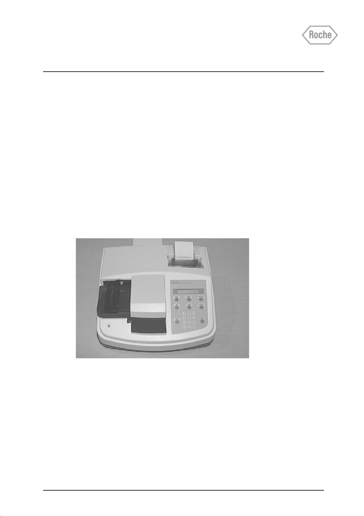
Miditron® Junior II
Service Manual
Service Manual Miditron® Junior II / ID 1997491 / MJ / 1.2 - February 2000 / Page 1
Page 2

Table of contents
Short operating instructions ........................................................................6
1. General Note..................................................................................................7
1.1 Limitations .............................................................................................................7
1.2 Mailing / telephone address................................................................................. 7
1.3 Security advice ......................................................................................................8
1.4 Confirmation declaration.................................................................................... 10
2. Documentation ............................................................................................ 11
2.1 Update service for this manual ..........................................................................11
2.2 Instrument code for service ...............................................................................11
3. Introduction ................................................................................................. 1 2
3.1 System description .............................................................................................12
3.1.1 Function Elements ............................................................................................ 13
3.1.2 Measuring Principle .......................................................................................... 15
3.1.3 Concentration Table (Program I) ....................................................................... 17
3.1.4 Changing Range Remisson Bordes.................................................................. 18
3.2 System Specification .......................................................................................... 19
3.3 Service Concept ..................................................................................................20
3.3.1 Service level....................................................................................................... 20
3.3.2 Handling of warranty and repairs ..................................................................... 20
4. Installation................................................................................................... 25
4.1 Checking for Damage in Transit......................................................................... 25
4.2 Unpacking ............................................................................................................25
4.3 Proper Setting ..................................................................................................... 25
4.4 Setting Up ............................................................................................................ 25
4.5 Inserting Printer Paper ....................................................................................... 27
5. Calibration ...................................................................................................2 8
6. Operation ..................................................................................................... 3 1
6.1 Overview ..............................................................................................................31
6.2 Normal Mode........................................................................................................ 32
6.3 Accelerated Mode................................................................................................ 32
6.4 Fast Mode.............................................................................................................32
6.5 Principle movement of the Miditron® Junior II.................................................33
7. Service mode and adjustment .................................................................... 3 4
7.1 How to make adjustments .................................................................................. 34
Service Manual Miditron® Junior II / ID 1997491 / MJ / 1.2 - February 2000 / Page 2
Page 3

Table of contents
7.2 General ................................................................................................................. 35
7.3 Procedure............................................................................................................. 35
8. Adjustment / Dismantling ........................................................................... 4 0
9. Mechanics .................................................................................................... 41
9.1 Mechanical moduls..............................................................................................41
9.1.1 T ransport arm .................................................................................................... 41
9.1.2 Tray..................................................................................................................... 41
9.1.3 T op of housing................................................................................................... 42
9.1.4 PCB Main ........................................................................................................... 43
9.1.5 PCB Interface ..................................................................................................... 44
9.1.6 Display ............................................................................................................... 45
9.1.7 Printer ................................................................................................................ 46
9.1.8 Status LED ......................................................................................................... 47
9.1.9 Keyboard ............................................................................................................ 48
9.1.10 PCB Measuring Head......................................................................................... 49
9.1.11 LB Measuring Head Home Position.................................................................. 5 0
9.1.12 LB Home P osition.............................................................................................. 51
9.1.13 Motor Belt Drive Cross T ransport...................................................................... 52
9.1.14 Motor Measuring Head Unit .............................................................................. 53
9.1.15 Tooth Bar Measuring Head Unit........................................................................ 54
9.1.16 Carrier for tray.................................................................................................... 55
9.1.17 Reference Field Carrier...................................................................................... 56
9.1.18 Crossbar complete ............................................................................................ 57
9.1.19 Cross Transport ................................................................................................. 58
10. Electronics................................................................................................. 5 9
10.1 Overview Electronics ..........................................................................................59
10.2 Power supply ....................................................................................................... 60
10.3 Electronic modules .............................................................................................62
10.3.1 PCB Main ........................................................................................................... 6 2
10.3.2 PCB Interface ..................................................................................................... 65
10.3.3 Display ............................................................................................................... 67
10.3.4 Printer ................................................................................................................ 67
10.3.5 Status LED ......................................................................................................... 67
10.3.6 Keyboard ............................................................................................................ 68
10.3.7 PCB Measuring Head......................................................................................... 68
10.3.8 LB Measuring Head Home Position.................................................................. 69
10.3.9 LB Home Position.............................................................................................. 69
Service Manual Miditron® Junior II / ID 1997491 / MJ / 1.2 - February 2000 / Page 3
Page 4

Table of contents
10.3.10 LB reference position ........................................................................................ 70
10.3.11 Motor Belt Drive Cross Transport...................................................................... 70
10.3.12 Motor Measuring Head Drive............................................................................. 71
10.4 Circuit diagram .................................................................................................... 72
10.4.1 PCB Main ........................................................................................................... 7 2
10.4.2 PCB Interface ..................................................................................................... 77
10.4.3 PCB Measuring Head......................................................................................... 81
11. Software..................................................................................................... 8 2
11.1 Overview ..............................................................................................................82
11.2 Flow Diagram of Menu Selection ....................................................................... 83
11.2.1 Flow Diagram of the W orklist Men u.................................................................. 84
11.2.2 Flow Diagram of the Working Mode Menu ....................................................... 85
11.2.3 Flow Diagram of the Reprint Menu ................................................................... 8 6
11.2.4 Flow Diagram of the Setup Menu ..................................................................... 8 7
11.2.4.1 Flow Diagram of Color Setup ........................................................................... 89
11.2.4.2 Flow Diagram of Clarity Setup .......................................................................... 90
11.2.4.3 Flow Diagram of Parameter Setup .................................................................... 91
11.3 Service/Status Software .....................................................................................92
11.4 Software update ..................................................................................................92
11.4.1 Software update via chip cards......................................................................... 92
11.4.2 Software update via printer interface................................................................ 93
11.5 Loading instrument settings via Download...................................................... 97
11.5.1 Specification of the INI-file................................................................................ 98
11.6 Saving instrument settings via Upload ...........................................................100
12. Interface ................................................................................................... 1 01
12.1 Host Interface .................................................................................................... 101
12.2 Character definitions, representation conventions........................................ 102
12.3 Protocols ............................................................................................................103
12.4 Upload timing and handshake ......................................................................... 106
12.5 Download timing and handshake ....................................................................108
12.6 Protocol structure ............................................................................................. 110
12.6.1 Protocol "/REP/": Repeat request ....................................................................110
12.6.2 Protocol "/SPM/": Start Communication .........................................................110
12.6.3 Protocol "/MOR/": Receipt confirmed/Request for next set ............................110
12.6.4 Protocol "/END/": End of communication .......................................................11 0
12.6.5 Protocol "/SPE-D/ + Data": Data protocol color + turbidity...........................11 1
Service Manual Miditron® Junior II / ID 1997491 / MJ / 1.2 - February 2000 / Page 4
Page 5

Table of contents
12.6.6 Protocol "/SPE-E/ + Data": Data protocol results .........................................11 1
12.6.7 Protocol "/SPE-A/ + Pat-Id.": Data protocol Pat-Id. .......................................112
12.7 Format of results-data : ....................................................................................112
12.7.1 Structure of results-data Programm-1 (International) : ...................................112
12.8 Procedures for checking test bytes................................................................. 114
12.8.1 European language variations of Miditron® software: LRC test bytes ..........114
12.8.2 American/Canadian language version of Miditron® Junior II software:........11 5
12.8.3 Automatic adaption to the test procedure used by the host ..........................11 6
13. T roubleshooting....................................................................................... 117
13.1 Error at self-test................................................................................................. 117
13.2 Repairable errors during normal mode........................................................... 118
13.3 Non-repairable errors during normal mode (Major Error) ............................ 119
13.4 Errors during INI-file Download....................................................................... 120
13.5 List of all error codes ........................................................................................121
14. Spare Parts .............................................................................................. 12 7
14.1 Complete spare part list.................................................................................... 127
14.2 Part i dentification ..............................................................................................128
14.3 Exploded view Miditron® Junior II...................................................................131
15. Instrument, Strips, Accessories ............................................................. 133
15.1 Complete list ...................................................................................................... 133
16. Interface Assignment .............................................................................. 1 3 4
16.1 Host/PC interface ..............................................................................................134
16.2 External Printer interface.................................................................................. 135
16.3 Barcode reader interface .................................................................................. 135
17. Routine Care and Cleaning ..................................................................... 1 3 6
17.1 General ............................................................................................................... 136
17.2 Cleaning .............................................................................................................136
Service Manual Miditron® Junior II / ID 1997491 / MJ / 1.2 - February 2000 / Page 5
Page 6

Short operating instructions
Directions in Brief
Please read carefully the sections marked with this symbol in the margin!
Miditron® Junior II is designed for ease of use. To carry out routine strip measurements in Normal Mode
(sequential reading with automatic consecutive numbering), proceed as follows :
Switch on Miditron
Please empty the waste tray.
Once the waste tray is empty and the self-check has finished, the analyz er is
ready . Y ou see displa yed.
1. Press <Start> and follow the display messages:
2. When the status LED flashes green and the beep tone sounds ("Dip Strip 1" is displayed), briefly dip
the test strip in the urine sample (for about 1 second) and then remove it again, drawing the edge of
the strip over the rim of the specimen container to wipe off excess urine.
3. While the status LED is green, you may insert the test strip, reagent zones upwards , into the insertion
area between the two guides on the leading edge of the strip receiving tray.
The end of the test strip must be supported by the rear inside edge of the strip receiving tray
(Fig. 10).
WARNING: To prevent injury, keep hands a way fr om the analyzer when it is transporting
test strips!
4. After about 20 seconds the first test strip will be transported from the waiting position to the
measuring position and "Please W ait" will be display ed. When the display shows "Dip Strip 2", repeat
the procedure for the second and any subsequent test strips.
®
Junior II. You see displayed:
Empty Waste Tray
"Please empty the waste tray"
READY - <START>
"The analyzer is ready to
measure"
5. The first test strip will be measured 60 seconds after it was dipped and the result will be automatically
printed as long as the internal printer was not disabled in the SETUP menu. When a strip is no longer
detected at the measuring position, Miditron® Junior II automatically returns to the initial state
("READ Y - <START>" is display ed).
IMPORTANT:
Before operating Miditron® Junior II for the first time, y ou have the option of entering various
settings in the SETUP menu.
For your own safety, and to avoid operator err ors, please read the f ollowing operating
instructions carefully .
Please refer to the relevant sections of the Operator’s Manual for information on selection of SET-
UP menu options, calibration, working with Patient ID’s, cleaning and maintenance.
Service Manual Miditron® Junior II / ID 1997491 / MJ / 1.2 - February 2000 / Page 6
Page 7

1. General Note
1.1 Limitations
The data and information provided in this manual correspond
to the state of knowledge existing at the time of introducing
the Miditron® Junior II on the market. Any important
changes will be taken into account in the next edition of this
manual.
The packaging leaflet should be regarded as authoritative.
This service manual was created for the telephone service
and technical service staff.
The operation manual contains special information for the
telephone service.
1.2 Mailing / telephone address
Service department, DA-ST
Telephone: +49 (0) 621 / 759 / 3227
Fax: +49 (0) 621 / 759 / 3985
Hot-line logistic (RA)
Telephone: +49 (0) 621 / 759 / 8094
Fax : +49 (0) 621 / 759 / 8093
When calling from outside Germany , add the international
dialing code at the beginning and omit the first ‘0’.
Service Manual Miditron® Junior II / ID 1997491 / MJ / 1.2 - February 2000 / Page 7
Page 8
1. General Note
1.3 Security advice
Please carefully read the paragraphs marked by a
warning triangle!
This instrument was constructed in accordance with DIN
VDE 0750, P art 1/DIN IEC 601, Part 1, “Medical Electrical
Equipment; Part 1: General Requirements for Safety”
and checked to meet all technical demands on safety
before leaving the factory .
The instrument received the „GS“ (Geprüfte Sicherheit =
safety-tested) label for meeting the safety requirements of
the VDE (V erein Deutscher Elektronik-Hersteller = Society of
German Electronics Manufacturers) and meets the
requirements of the MedGV (Medizinische Geräteverordnung
= Medical Instrument Regulation).
T o maintain these conditions and guarantee saf e operation,
the operator should read this information and observe the
warnings given in these operating instructions.
The instrument should be used only with the external power
supply included in the delivery .
This instrument belongs to Protection Class I (protective
conductor).
Do not insert the plug into any type of AC outlet other than a
shock-proof outlet. Do not use an extension cord without a
protective conductor to prevent that the protective effect is
circumvented.
Interrupting the earth conductor inside or outside of the
instrument or disconnecting the earth conductor lug
may create a hazardous situation for the operator .
Do not open the covers or remove parts that cannot be
opened or removed by hand, as this can e xpose live parts.
Connectors may also be live. Any adjustment, maintenance
or repair on an opened instrument with the power on should
be carried out only by trained personnel authorized by Roche
Mannheim who are aware of the danger involved.
If you suspect that the instrument can no longer be operated
safely, turn it off and take steps to ensure that it cannot be
turned on accidentally . Make certain that the Miditron
Junior II is oper ated by trained personnel only.
®
T o prevent injury , keep hands a way from the analyzer
when it is transporting a strip.
A personal computer or printer connected to the analyzer
Service Manual Miditron® Junior II / ID 1997491 / MJ / 1.2 - February 2000 / Page 8
Page 9

1. General Note
must meet the regulations of EN 60950, UL 1950 or CSA
C22.2 No. 950.
General Information:
The data and information contained in this manual are
current as of issue. Any basic changes will be included in
subsequent editions. In case of uncertainty, the package
insert included with the product in question shall prevail.
The instrument meets the requirements of Overvoltage
Class 2 and Pollution Class 2.
Medical Instrument Regulation („MedGV“)
MedGV is a safety regulation for technical medical
instruments (effective only in Germany).
According to the MedGV of 01/14/85, the Miditron® Junior II
is classified in Group 3. The user m ust follow the proper
guidelines for Group 3.
Reference:
Regulation on Safety of Technical Medical Instruments.
Author: Adolf Krebs, ISBN 3-921958-41-S, 1985 Bibliomed.
Published by: Medizinische V erlagsgesellschaft mbH,
Melsungen.
Miditron® Junior II should be used by qualified persons
only.
Service Manual Miditron® Junior II / ID 1997491 / MJ / 1.2 - February 2000 / Page 9
Page 10
1. General Note
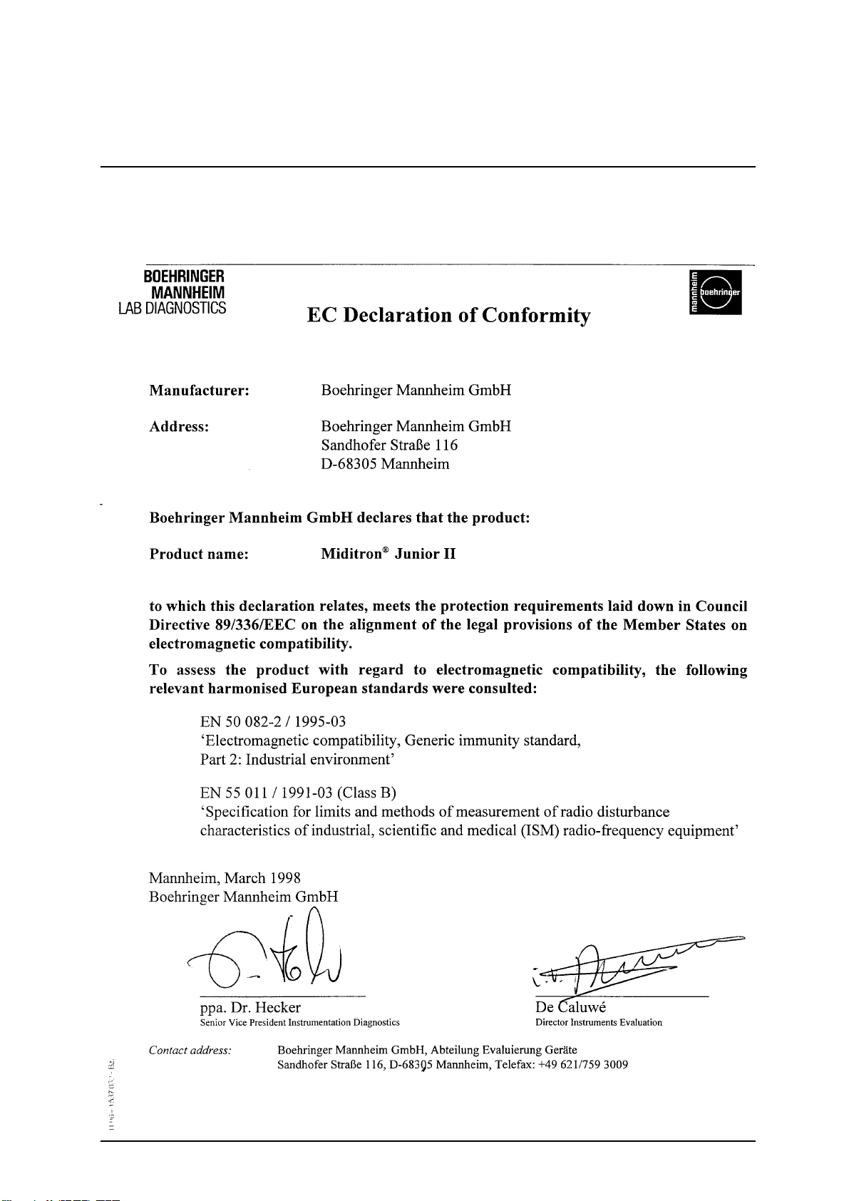
1.4 Confirmation dec laration
Confirmation declaration for electromagnetic compatibility
according to the laws of the European Union.
Service Manual Miditron® Junior II / ID 1997491 / MJ / 1.2 - February 2000 / Page 10
Page 11

2. Documentation
2.1 Update service for this manual
New information and modifications will be sent via T echnical
News. Please send us your name and address to ensure
you receive updates automatically.
Update Service:
Fax this page to Technical Service-Roche Mannheim
+49 (0)621 759 3985
Name:......................................................
Address:..................................................
..................................................................
..................................................................
F AX No. + ____ _____________________
You will find the version identification in the bottom line of
every page.
Explanation of the index:
Service Manual Miditron® Junior II / ID 1702602 / MJ / Vers.
1.0 - June 1998 / P age 5
Instrument: Miditron® Junior II
Order- number: 1702602
Instrument code: MJ
Version: 1.0
Date of edition: June 1998
Page: 5
2.2 Instrument code for service
The service code of Miditron® Junior II is: MJ
Service Manual Miditron® Junior II / ID 1997491 / MJ / 1.2 - February 2000 / Page 11
Page 12

3. Introduction
3.1 System description
Urine test strips simplify laboratory diagnosis through their
ease of use, sensitivity and specificity. These benefits allo w
you to identify pathological changes in the urine quickly and
reliably.
Automated urinalysis with Miditron® Junior II assures that
the reading of results is standardized by eliminating
potential sources of error associated with visual reading of
test strips (such as unfavourab le lighting conditions at the
workplace, differences in operators’ ability to discriminate
between colours and keep to prescribed times, etc.). The
test strips used are multi-parameter strips for measuring
specific gravity, pH, leukocytes, nitrite, protein, glucose,
ketone, urobilinogen, bilirubin and erythrocytes in urine.
Service Manual Miditron® Junior II / ID 1997491 / MJ / 1.2 - February 2000 / Page 12
Page 13
3. Introduction
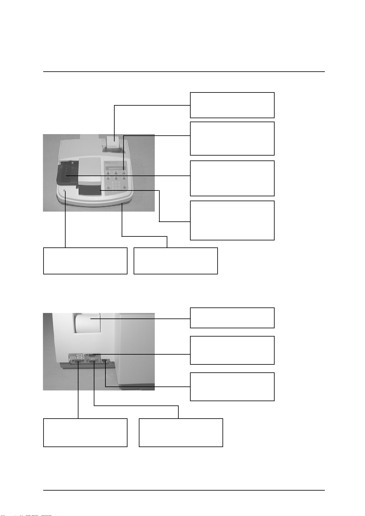
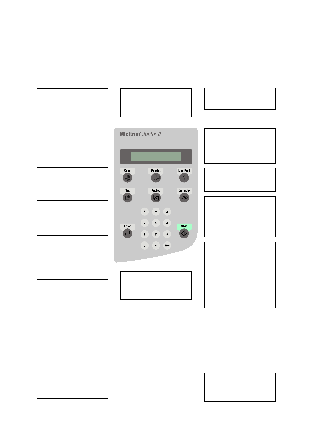
3.1.1 Function Elements
Built in printer with lid
for documentation of the
results
Keyboard/ Displa y
Contains 6 function keys , 10
num. k eys and liquid crystal
display
T ransport arm
Transports test strip from
wait position into measuring
position
Waste tray
Three functional areas, test
strip insertion, incubation/
measurement area and
waste container
Status LED
3 different colours indicates
the status of the instrument
Serial interface
Used to connect to a
barcode reader
Program chip card
Contains program f or SW
update
Printer paper
Thermal paper
Serial interface
Used to connect to external
printer
DC- socket
To connect the external
power supply
Serial interface
Used to connect to a host,
PC
Service Manual Miditron® Junior II / ID 1997491 / MJ / 1.2 - February 2000 / Page 13
Page 14
3. Introduction
Color
For manually selecting
colour and clarity for
inclusion with results.
Set
Used to select a menu
option.
Enter
Used to terminate keyboard
input, e.g. <0-9> and to
confirm an option or a
procedure.
Reprint
Reprints the patient report(s)
as defined in the Reprint
menu.
Display
The display consists of 1 line
of 16 characters.
Line Feed
advances paper one line at a
time or advances
continously while key is
depressed
Calibrate
Starts the calibration
procedure.
Paging
Used to scroll forwards
vertically through menus
without branching to menu
options and without saving
settings.
<0-9> and <.>
Used to enter (alpha)
numeric values.
External power supply ,
provides the instrument with
+5V DC and +12V DC
ç
Backspace ke y f or correcting
input, scrolling backwards or
jumping back one
Start
Used to start test strip
measurement, also to
escape from menus back to
"READ Y - <Start>", "ACC
MODE Start" or "FAST
MODE <START>", to stop
printing during Reprint, and
to acknowledge warning
messages and prompts.
Power cord
(Country specific)
Service Manual Miditron® Junior II / ID 1997491 / MJ / 1.2 - February 2000 / Page 14
Page 15
3. Introduction
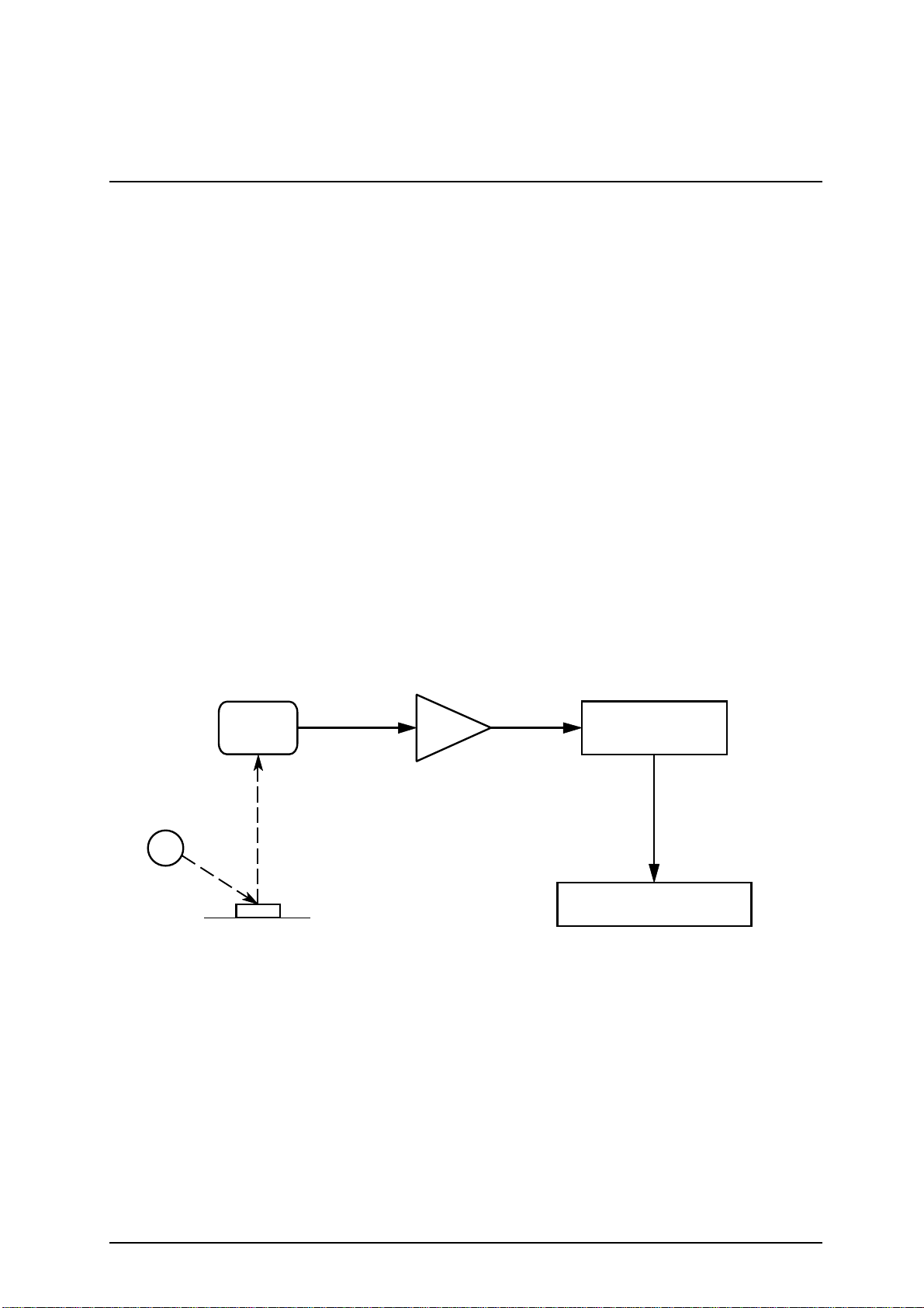
3.1.2 Measuring Principle
Miditron® Junior II is a semi-automated reflectance
photometer for in-vitro semi-quantitative reading of urine test
strips from Roche Mannheim. The light sources (lightemitting diodes, LED’s for short) and reading times are
optimized for the reaction chemistry and colour development
occurring on the test pads.
The measuring head of Miditron® Junior II contains 3 LED’s
of differing wav elengths. The test strip is held stationary at
the measuring position and the measuring head moves over
each test pad in turn, starting from a "Reference position"
used to test the optical system.
During measurement, Miditron® Junior II checks that the
test strip is properly positioned under the measuring head by
carrying out a plausibility check on the light that is reflected.
If the strip is not properly positioned under the measuring
head, Miditron® Junior II prints an error message.
LED
1
Reading is done electro-optically , as f ollows:
Detector Analog-to-Digital Converter Microprocessor
3
2
4
Test Area
Concentration Result
An LED (1) flashes light of a defined wavelength at an
optimum angle onto the surface of the test pad (2). The light
hitting the surface is reflected with an intensity that is
dependent on the colour of the test pad, and is received by
a photodiode detector (3) positioned directly above the test
pad. The detector sends an analogue electrical signal to the
analogue-to-digital converter (4), which converts it to a digital figure. The microprocessor (5) corrects the digital figure
based on a value from an internal reference pad and
converts it to a relative value by scaling to a calibration
standard, and then computes the absolute reflectance value.
5
Service Manual Miditron® Junior II / ID 1997491 / MJ / 1.2 - February 2000 / Page 15
Page 16
3. Introduction
The semi-quantitative concentration result is determined by
comparing the absolute reflectance value with the so-called
range boundaries ( = constant, parameter-specific
reflectance values stored in the analyzer).
Results can be printed out, saved in memory, and sent to a
computer.
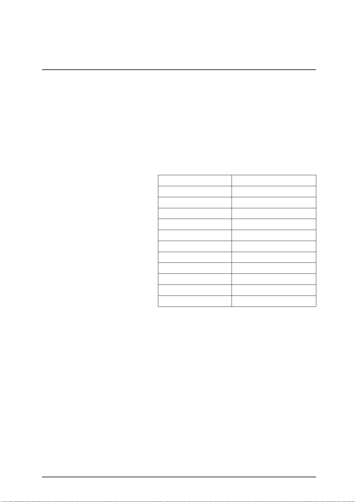
The wav elengths of the LED’s used to measure each of the
urine test strip parameters are listed in the table below . The
results of certain parameters are improved through the use
of two different wa velengths . The third LED is for future
options
Parameter Measuring Wave length [nm]
Specific Gravity 620
pH 557 and 620
Leukocytes 557
Nitrite 557
Protein 557
Glucose 557
Ketone 557
Urobilinogen 557
Bilirubin 557
Erythrocytes 557 and 620
Color 557 and 620
The photometric reflectance measurement for all of the
parameters is carried out after an incubation time of 60
seconds. As with earlier urine analyzers from Roche Mannheim, allowance for intrinsic urinary colour, which is a
recognized interfering factor , is made through measurement
of a blank reagent pad, the so-called "compensation pad".
Upon immersion into the urine sample, the compensation
pad absorbs the sample liquid and assumes the intrinsic
colour of the urine. Measuring the compensation pad helps
prevent false positives when the urine sample is strongly
coloured.
In strongly alkaline urine samples, Miditron® Junior II
automatically corrects the result obtained when the test pad
for specific gravity is read.
Miditron® Junior II reads the strip and determines urine
colour by ev aluating the compensation pad. The settings
necessary for this are selected in the Setup menu. Whether
the colour is to be printed together with the results is also
defined in the Setup menu.
Service Manual Miditron® Junior II / ID 1997491 / MJ / 1.2 - February 2000 / Page 16
Page 17

3. Introduction
3.1.3 Concentration T able (Program I)
Miditron® Junior II prints the test results in the following
concentration ranges:
Parameter Conventional SI Arbitrary (Standard)
Specific Gravity 1.000 1.000 1.000
(SG) 1.005 1.005 1.005
1.010 1.010 1.010
1.015 1.015 1.015
1.020 1.020 1.020
1.025 1.025 1.025
1.030 1.030 1.030
pH 5 5 5
666
6.5 6.5 6.5
777
888
999
Leukocytes neg. neg. neg.
(LEU) 25 /µl 25 /µl +
100 /µl 100 /µl ++
500 /µl 500 /µl +++
Nitrite neg. neg. neg.
(NIT) pos. pos. pos.
Protein neg. neg. neg.
(PRO) 25 mg/dl 0.25 g/l +
75 mg/dl 0.75 g/l ++
150 mg/dl 1.5 g/l +++
500 mg/dl 5 g/l ++++
Glucose norm. norm. neg.
(GLU) 50 mg/dl 3 mmol/l +
100 mg/dl 6 mmol/l ++
300 mg/dl 18 mmol/l +++
1000 mg/dl 56 mmol/l ++++
Ketone neg. neg. neg.
(KET) 5 mg/dl 0.5 mmol/l +
15 mg/dl 1.5 mmol/l ++
50 mg/dl 5 mmol/l +++
150 mg/dl 15 mmol/l ++++
Urobilinogen norm. norm. neg.
(UBG) 1 mg/dl 17 µmol/l +
4 mg/dl 68 µmol/l ++
8 mg/dl 135 µmol/l +++
12 mg/dl 203 µmol/l ++++
Bilirubin neg. neg. neg.
(BIL) 1 mg/dl 17 µmol/l +
3 mg/dl 50 µmol/l ++
6 mg/dl 100 µmol/l +++
Erythrocytes neg. neg. neg.
(ERY) 10 /µl 10 /µl +
25 /µl 25 /µl ++
50 /µl 50 /µl +++
150 /µl 150 /µl ++++
250 /µl 250 /µl +++++
Service Manual Miditron® Junior II / ID 1997491 / MJ / 1.2 - February 2000 / Page 17
Page 18

3. Introduction
3.1.4 Changing Range Remisson Bordes
The boundaries of the reflectance ranges used by Miditron
Junior II to compute and output the test results were derived
from rigorous comparative tests carried out by Roche Mannheim with native urine. If required, the factory-set default
ranges for Miditron® Junior II may be changed to suit
individual laboratories’ requirements. Results obtained based
on individually modified ranges are flagged with an asterisk *
under the "Urinalysis" headline on the patient report.
The ranges for the parameters pH and SG cannot be
modified; nor can the thresholds for wavelength changes for
pH and ER Y .
Operator´s Manual outlines how ranges can be selected.
Roche Mannheim can give no guarantee as to the
accuracy of results when range boundaries have
been changed.
®
Service Manual Miditron® Junior II / ID 1997491 / MJ / 1.2 - February 2000 / Page 18
Page 19

3. Introduction
3.2 System Specification
Dimensions: Height: 195 mm
Width: 349 mm
Depth: 470 mm
Weight: 7.45 kg
Interfaces: 3 serial RS 232 C interfaces
(host/PC, barcode reader , external printer)
Po wer Supply: External Universal Pow er Supply Model No. 78-095-0300
with integral ON/OFF s witch
Input: 110 V - 240 V; 50-60 Hz; 0.4-0.2 A
Output: 5 V 2.0 A
12 V 2.0 A
Power Consumption: Operation: 30 W
Standby: 15 W
System Description: Type: reflectance photometer
Light source: LED’s (light emitting diodes)
Wavelengths: 557 nm, 620 nm
(the 656 nm LED is for future options)
Measuring head: 1 measuring head with 3 LED’s
Work flow: approx. 36 seconds (Normal Mode)
approx. 20 seconds (Accelerated Mode)
approx. 12 seconds (F ast Mode)
Incubation time: 60 seconds
Printer: Seiko thermal line printer
Display: liquid crystal display , 1 line, 16 characters
Environmental conditions:
Operating Non-Operating
Temperature: +15°C - +34°C -20°C - +60°C
Relative humidity: 20 % 80 % 20 % 95 %
Optimum Opt. T emperature: +22°C - +26°C
operating conditions: Opt. Rel. Humidity: 30 % 60 %
Service Manual Miditron® Junior II / ID 1997491 / MJ / 1.2 - February 2000 / Page 19
Page 20

3. Introduction
3.3 Service Concept
3.3.1 Service level
From the early stage of development, Miditron® Junior II
was designed for simple error detection and easy
exchangeability of modules. This gives the service
workshops the possibility of a fast and easy repair of the
instrument on service level A (module level). No big stock or
expensive equipment is necessary and service technicians
are easier to train. Also, a permanent technical
improvement in la yout and economic production.
SMD-technology increases reliability on better economical
basis in production. Repair costs often do not relate to
production costs for ne w parts with the latest improvement.
This cuts the number of repairable parts.
On repairable modules the quality and function is alwa ys
provided by the manufacturer according to the latest
technology . This keeps Miditron
highest quality level.
®
Junior II alwa ys on the
The exchange price for modules will be kept on a lo w le v el
to guarantee repairs, on economical basis.
3.3.2 Handling of warranty and repairs
Warranty period f or instruments and spare parts
The warranty period for instruments is 16 months
starting with the date of shipment ex works Mannheim/
Federal Republic of Germany or 12 months starting with
the date of the first installation, whichever period is
shorter.
The warranty period for spare parts is 6 months from
installation date of the part, however not longer than 24
months after having delivered ex w orks Mannheim/
Federal Republic of Germany.
Hint:
In case the instrument has a remaining warranty period
of more than 6 months, the parts remain under warranty
until the warranty period of the instrument expires.
Service Manual Miditron® Junior II / ID 1997491 / MJ / 1.2 - February 2000 / Page 20
Page 21

3. Introduction
Handling of warranty claims
The warranty claim has to be handled via Return
Authorization procedure or accepted equivalent. Please
answer all the questions on the RA form with the greatest
care.
Especially a detailed fault description is needed or the
warranty claim will not be accepted by the manuf acturer .
Complete instruments are not accepted unless this has
been agreed with the service department of the relevant
product group responsible at RD GmbH.
Important information:
- Only parts marked with „A“ in the price list are
generally accepted under warranty .
- Only return those parts marked with „R“ in the spare
parts price list.
- Warranty claim f or “R” parts will be accepted, if the
part was returned to Mannheim.
- All defective parts ( non-“R“ and „A“ parts ) should
be kept on stock for a period of 7 months. In case the
manufacturer needs the part for inv estigation it will be
requested from Mannheim.
- All parts returned to Mannheim and not requested by
Mannheim will be send back at the expense ofthe
countries.
- The RA claim for warranty has to be in Mannheim no
later than 8 weeks after the problem date.
Exclusion of warranty
The aforementioned warranties do not apply in case of
improper use, handling, transportation or storage, faulty
installation, repair or maintenance, chemical influence or
contamination as well as damages resulting from that,
failure to follow operating instructions, alterations or
modifications of instruments or parts thereof not
authorized or recommended by RD GmbH and resulting
damages, normal wear and tear and in case of other
circumstances beyond the control of RD GmbH.
Service Manual Miditron® Junior II / ID 1997491 / MJ / 1.2 - February 2000 / Page 21
Page 22

3. Introduction
Handling of repairs
As a general rule, all instrument repairs should be carried
out by authorized and trained personnel only .
Repair of parts marked with „R“
Parts which are economically worth repairing are marked
with „R“ in the spare parts price list. N ew and repaired
parts could be recognized by different material numbers
(language version).
(e.g. ne w part: 1234567-001, repaired part: 1234567- 984)
Repaired parts should be ordered together with new parts
via the order processing department in Mannheim (OUVDG). P arallel to the ordering process of a repaired part,
the defectiv e part should be returned together with the
filled RA form (giving full details of the defect and marked
choice box with repair) to Logistic Instruments (Goods
Receipt) in MA-Wohlgelegen (LI-L V).
Repair of instruments
Complete instruments are not accepted for replacement
or repair unless this has been agreed with the product
group responsible at RD GmbH.
Before replacement or repair can take place, the validity
of the request must be examined and the question of
costs must be settled in a written agreement with RD
GmbH.
Terms of delivery
Shipments to the countries with the routine truck are
c.i.f./ shipments outside this procedure are ex works
Mannheim .
Emergency shipments require additional costs to be
charged.
Handling of costs
“Repaired”-parts (Material-No. 1234567-984) are
shipped at a repair price. In case the defective parts
are not returned within 3 or 8 weeks for european or
oversea countries after ordering the repaired part, the
countries will be charged later on with the difference
to the new price.
Service Manual Miditron® Junior II / ID 1997491 / MJ / 1.2 - February 2000 / Page 22
Page 23

3. Introduction
After the receipt of a warranty request for “A”-parts, RD-G
will credit 100 % of the currently effective ex MA price.
In case the manufacturer does not accept the warranty
request, the countries will be charged lateron with the Rprice for R-parts and the new price for non R-parts.
RA form
Return Authorization
Please answer all the questions on the RA form with the
greatest care and sign the form.
- Country code
- Problem date
- Type of instrument
- Serial no. of the instrument
- Installation date of instrument
- Defective instrument or spare part
- Part number and material number of the spare part
- Old / new serial no.
- Fault description
- Alarm code
- Service / workshop report no.
In case of instrument out of warranty
- Installation date of spare part
All returned parts should be individually labeled with the
corresponding RA no. and shipped together with the
completed RA form to:
Roche Diagnostic Mannheim GmbH
Logistic Instruments
RA Management
Friedrich Ebert Str. 100
D - 68167 Mannheim
Germany
Service Manual Miditron® Junior II / ID 1997491 / MJ / 1.2 - February 2000 / Page 23
Page 24
3. Introduction
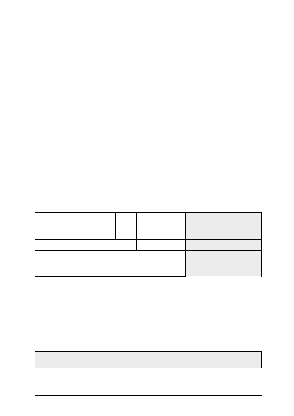
RA form
In the following please find important hints on how to fill in
the RA-Form correctly .
ROCHE DIAGNOSTICS MANNHEIM GmbH
Friedrich-Ebert-Strasse 100 T elefon : +49 (621) 759 81 84
D-68167 Mannheim Fax : +49 (621) 759 80 93
Germany
Return Authorization
No.:
Country code:
Date:
Instrument:
Serial No.:
Installation date:
Spare Part:
Customer: Address:
(will be filled in by RD)
Part No.: Qty.: Part Name: Repair Comments
Mat.-No.: Warranty
Installation date of Spare Part: Warranty Repair
OLD serial No.: Modification
NEW serial No.: Replacement
Fault Description:
Alarm Code:
Service Report No.: Workshop Report No.:
Place: Date: Signature:
Remarks (will be filled in by RD) NOS Credit FC
RD
Service Manual Miditron® Junior II / ID 1997491 / MJ / 1.2 - February 2000 / Page 24
Page 25
4. Installation
4.1 Chec king f or Dama ge in Transit
Miditron® Junior II is shipped in one package. Please
contact the supplier or carrier immediately regarding any
damage that may hav e occurred in transit.
4.2 Unpacking
Unpack the Miditron® Junior II accessories and check that
all are present:
- Operator’s Manual
- T r ansport Arm
- Universal Pow er Adapter with Connecting Cable
- Printer Paper (5 Rolls)
- Power Cord
Fig. 31
4.3 Proper Setting
Set up Miditron® Junior II on a firm and straight surf ace. Do
not expose the analyzer to direct sunlight or to an y other
direct light source.
4.4 Setting Up
Do not start the analyzer immediately if it has
been subject to an abrupt change in
temperature or humidity .
1. Check that the strip receiving tray / waste tray is correctly
positioned in its holder.
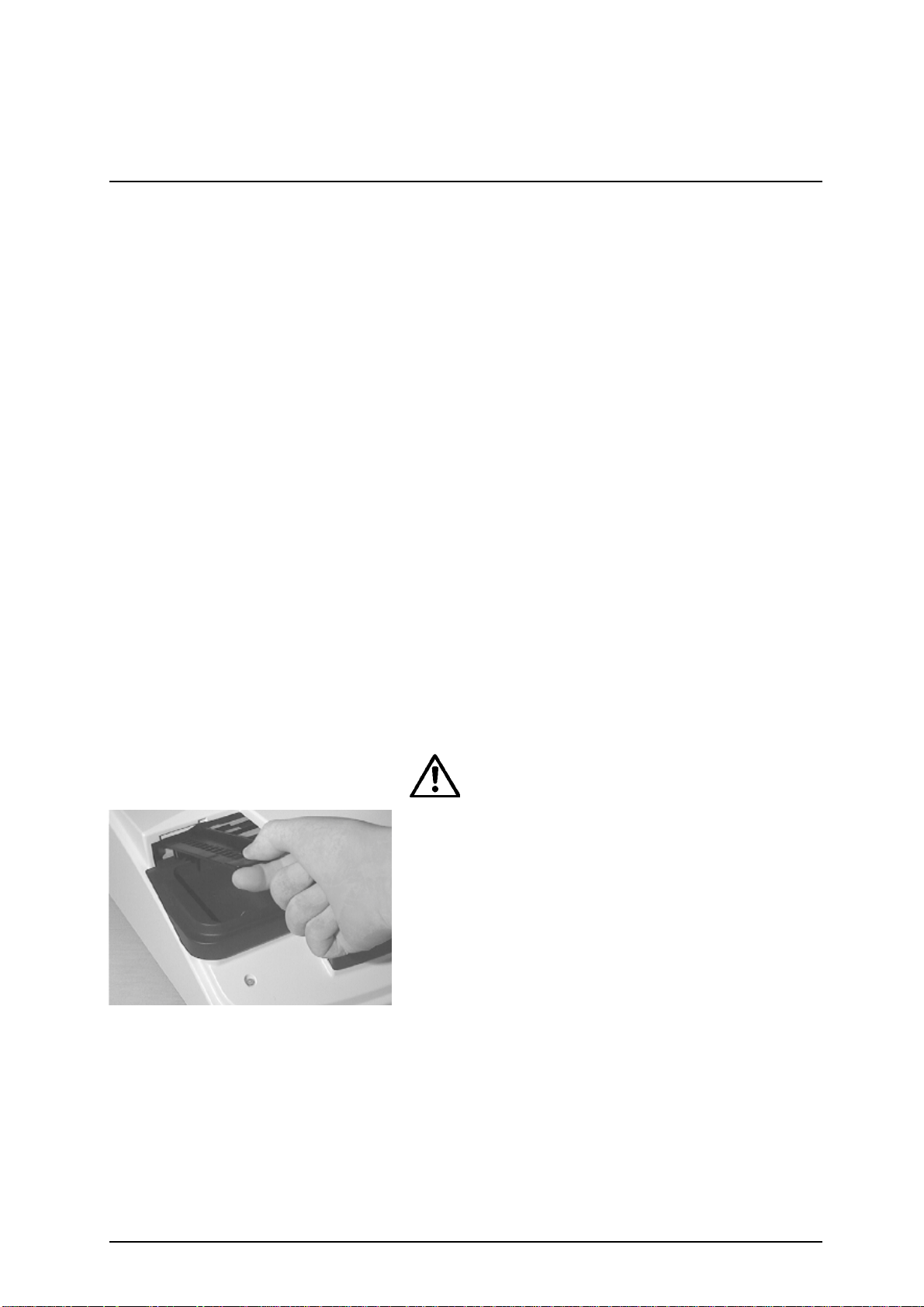
2. Attach the transport arm. Grasp the handle end and,
while holding it at an angle of 45° from the vertical, insert
it as far as it will go along the visible guide, then push
down so it snaps into position (Fig. 31).
Service Manual Miditron® Junior II / ID 1997491 / MJ / 1.2 - February 2000 / Page 25
Page 26
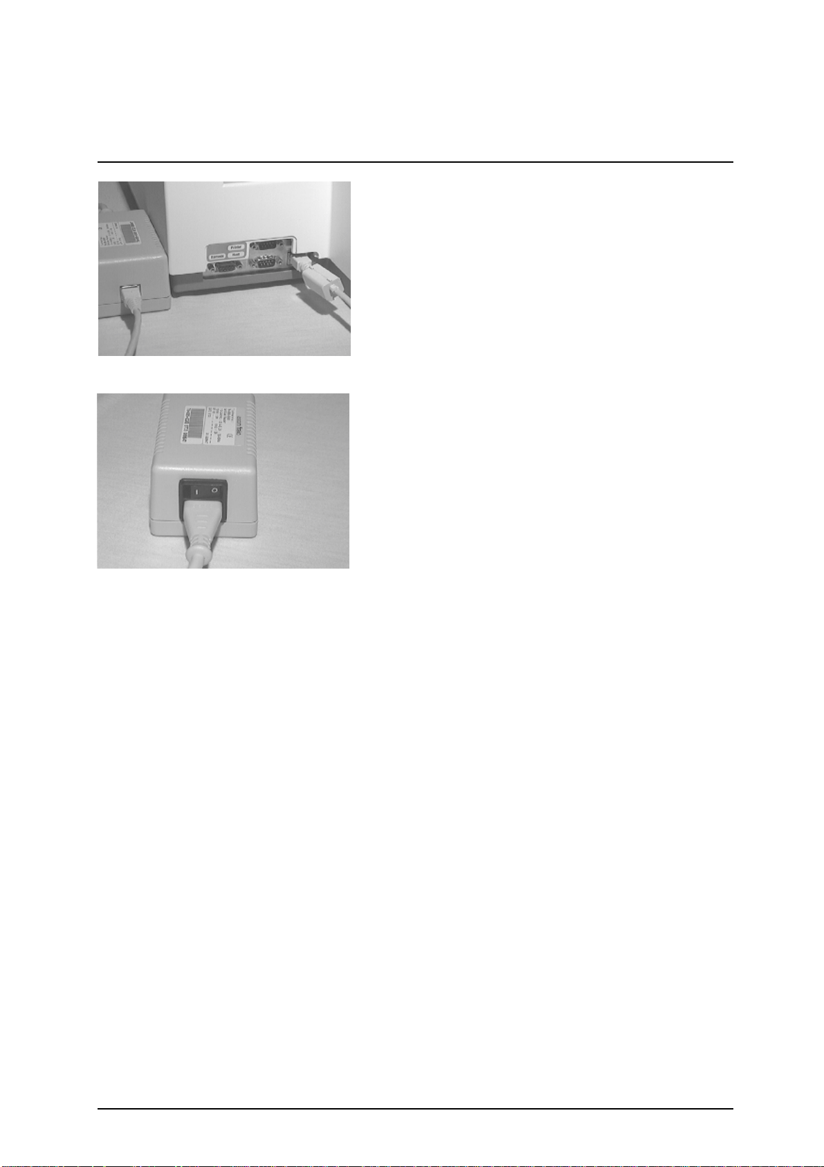
Fig. 32
4. Installation
3. Plug one end of the power connector cable into the
power sock et at the rear of the instrument and the other
end into the AC power adapter (Fig. 32). Plug the AC
power cord first into the AC po wer adapter and then into
an appropriate AC wall socket.
4. When the AC power adapter is switched on (Fig. 33),
Miditron® Junior II automatically runs a self-check. The
message "Empty Waste T ray" is then displa y ed. This
message is displayed whene ver the analyz er has been
left switched off or in Standby Mode ov ernight. Press
<Start> to cancel the "Empty Waste Tray" message. The
analyzer will display "READY - <ST AR T>" or "Please
Calibrate".
5. If "Please Calibrate" is displayed, press <Start>. This will
allow you to b ypass calibration at this point if y ou wish to
change the user interface language. (The def ault
language setting is English.)
Fig. 33
6. Press <Paging> until "Setup" is display ed. Press <Set>
until the desired language appears in the display, then
<Enter> to confirm your selection. Pressing <Start>
closes the setup routine and returns you to "READY <ST AR T>" or "Please Calibrate".
7. Insert the roll of printer paper as shown in Figs 34 to 37.
(refer to Section 4.5).
8. Y ou ma y then calibrate the analyz er (ref er to Section 6).
Service Manual Miditron® Junior II / ID 1997491 / MJ / 1.2 - February 2000 / Page 26
Page 27
4. Installation
Fig. 34
Fig. 35
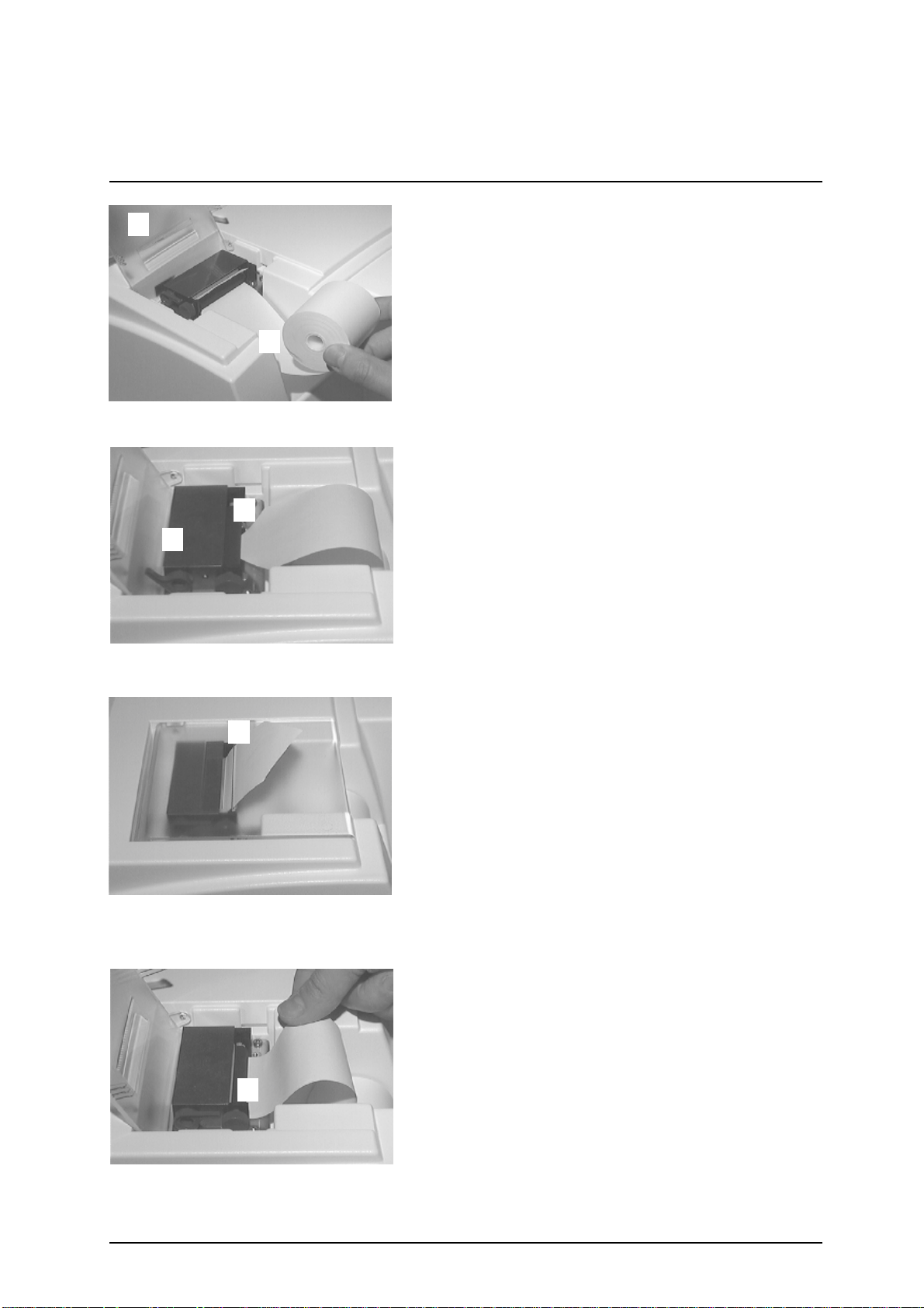
4.5 Inserting Printer Paper
The printer paper (thermal paper) is heat-sensitive and
must be kept aw a y from direct sunlight and high
temperatures. Chec k that there is sufficient printer paper in
the printer paper compartment. To insert a new roll of printer
paper, follo w one of the tw o methods below:
Method 1:
1. Open the printer cover (Fig. 34).
2. Remove the old core and any remaining paper (Fig.
34).
3. Place a new roll of paper in the printer paper
compartment (with the end of the paper pointing
downwards and towar ds the printer) (Fig. 34).
4. Lift the lever on the printer (Fig. 35).
5. Cut off the end of the paper at an angle and insert it into
the paper slot on the printer (Fig. 35).
6. Pull the paper through the printer and lower the le ver
(Fig. 35).
Fig. 36
7. Feed the paper through the slot in the printer cover and
then close the printer cover (Fig. 36).
8. Press <Line Feed> to advance the paper.
Method 2:
1. Open the printer cover (Fig. 34).
2. Remove the old core and any remaining paper (Fig.
34).
3. Place a new roll of paper in the printer paper
compartment (with the end of the paper pointing
downwards and towar ds the printer) (Fig. 34).
4. Cut off the end of the paper square and insert it into the
paper slot on the printer (Fig. 37).
5. Press <Line Feed> to advance the paper.
6. Feed the paper through the slot in the printer cover and
then close the printer cover (Fig. 36).
Fig. 37
Service Manual Miditron® Junior II / ID 1997491 / MJ / 1.2 - February 2000 / Page 27
Page 28

5. Calibration
Miditron® Junior II is factory-calibrated bef ore shipment.
The analyzer must be calibrated again before being used f or
the first time, and then every 14 da ys. The message "Please
Calibrate" will appear in the display whene v er the 14-da y
period has expired.
Calibration is a procedure in which allowance is made f or
changes in the optical system by reference to an internal
compensation pad. If there hav e been marked changes ,
caused for instance b y soiling of the ref erence pad or
because of low-level light output from a def ectiv e LED, an
error message is printed out.
Control-Test M calibration strips (Catalogue Number 1 379
194) are standardized grey plastic strips that hav e constant,
defined reflectance characteristics. Calibration strips should
not be removed from their container until shortly before use,
and should be used once only. Do not touch the elevated
grey areas on the strip (see the package insert for more
details). Before calibr ating, ensure that the tr ansport arm
and strip receiving tray / waste tra y are clean and dry.
READY - <START>
"The analyzer is ready to
measure in Normal mode"
ACC MODE <START>
"The analyzer is ready to
measure in Accelerated mode"
FAST MODE<START>
"The analyzer is ready to
measure in Fast mode"
Please Calibrate
"The analyzer needs calibrating"
Insert Cal Strip
"Insert calibration strip"
Press <Calibr.>
"Press the Calibrate key"
Calibrating
"Calibration being carried out"
To calibrate, proceed as follo ws:
Press <Calibrate> when you see displa yed:
Note:
The "Please Calibrate" message can be bypassed by
pressing <Start>. In this case, a message will be printed
on the patient report.
Two messages will appear alternately in the display:
Place the Control-Test M calibration strip in the centre of the
strip receiving tray.
Press <Calibrate> again. The calibration strip is transported
into the analyzer and you see the follo wing display ed:
After about 60 seconds, a printout will occur as long as the
printer has not been disabled in the Setup menu.
Service Manual Miditron® Junior II / ID 1997491 / MJ / 1.2 - February 2000 / Page 28
Page 29

5. Calibration
SW.Vers. 1 1.00
22.01.1998 9:21
Calibration o.k.
557 620 657
0 64.50 63.60 63.20
1 64.49 63.76 63.11
2 64.40 63.73 64.56
3 64.44 63.82 63.48
4 64.44 63.70 63.39
5 64.32 63.76 63.37
6 64.05 63.50 63.34
7 64.40 63.67 63.26
8 64.55 63.64 63.22
9 64.17 63.70 63.04
10 64.55 63.67 63.28
11 64.35 63.71 63.43
SW.Vers. 1 1.00
22.01.1998 9:21
Cal. Err. ##
Calibration successful:
Printout of reflectance
values in % R.
Calibration unsuccessful:
Recalibration necessary.
The printout quotes the current software version number ,
the date and time of calibration, and the positions of the
individual test pads on the calibration strip, together with the
measured reflectances in % R at the respective
wav elengths. Position 0 is the internal reference pad.
If, after sev eral repeat calibrations , y ou still receive the
message "Recalibrate !", please refer to Section 8
"Troubleshooting". During the calibration procedure, the
values read from the calibration strip are compared with the
stored calibration values. The calibration procedure is as
follows:
Service Manual Miditron® Junior II / ID 1997491 / MJ / 1.2 - February 2000 / Page 29
Page 30
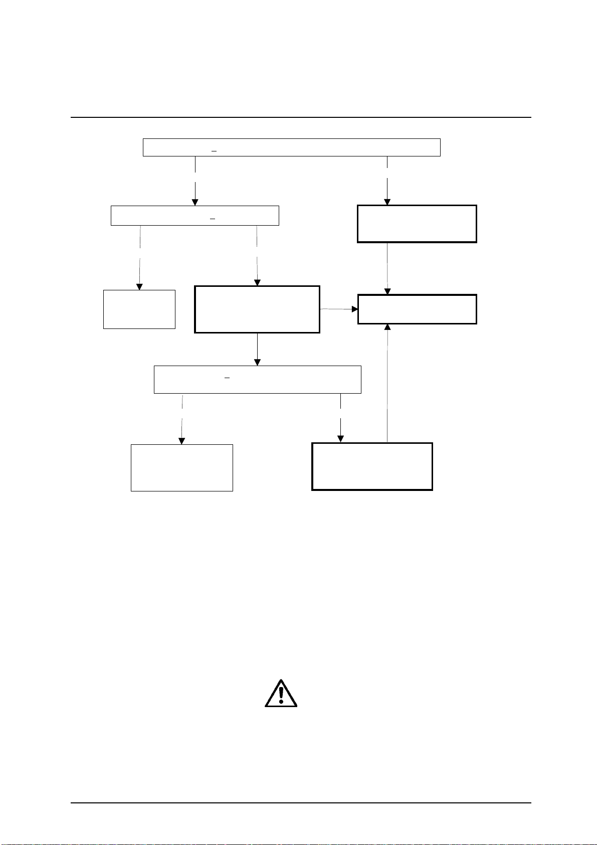
5. Calibration
Difference of < 10 % between measured value and reference value
Difference of < 1 % R
Yes
Stored
calibration is still
valid.
Calibration is valid.
New calibration values
will be stored.
Yes
No
Cal. Error 10 - 45
Calibration not valid.
Measurement of a second
calibration strip necessary
Difference of < 1 % R between 1st and 2nd
calibrat i o n st r ip
No Yes
Calibration not valid.
Recalibration necessary.
No
Cal. Error 50 - 85
Calibration not valid.
Recalibration necessary.
Display message:
"Recalibrate !"
Cal. Error 10 - 45
Miditron® Junior II is ready to read as long as there are
valid calibration values stored in the analyzer . Calibration
every 2 weeks is recommended. If calibration cannot be
carried out for any reason, e.g. because there are no
Control-Test M calibration strips available, y ou can bypass
the calibration procedure and continue reading by pressing
<Start> at the "Please Calibrate !" prompt. Miditron® Junior
II then uses the stored calibration values to carry out further
readings.
Note: In this case, "Calibration is necessary" will be printed
on the results report.
Roche Mannheim can give no guarantee as to the
accuracy of results if the analyzer has not been
calibrated.
Service Manual Miditron® Junior II / ID 1997491 / MJ / 1.2 - February 2000 / Page 30
Page 31

6. Operation
6.1 Overview
Miditron® Junior II is e xtremely easy to use. For normal,
routine reading of test strips (Normal Mode) simply press
<Start> to begin reading when you see "READ Y <START>".
The user is guided by display messages and the status
LED . The status LED appears in one of three states:
- Red = Read display messages,
- Flashing green = Dip a test strip,
- Green = Insert the test strip.
There is also a choice of three operating modes (further
details see Operators´Manual):
- Normal Mode
- Accelerated Mode
- Fast Mode
Fig. 60
When dipping a test strip in the sample, always ensure that
all of the test pads are completely covered. Place the test
strip, with its test pads facing upwards, to the right of the
"NO STRIP" warning and between the two elev ations along
the front edge of the strip receiving tray. The far end of the
test strip must be resting on the inner lip at the rear of the
tray (Fig. 60).
Miditron® Junior II automatically terminates the series
when no further strip is inserted.
You can change between the three operating modes by
making the appropriate selection in the Working Mode
menu (see Operators´Manual).
Miditron® Junior II automatically assigns consecutive
sequence numbers to samples. Numbering automatically
starts with 1:
a) whenever the date has changed (also , the displa y reads
"Empty Waste Tray"), and
b) following er asure of the results memory.
The waste container integrated into the strip receiving tray
can hold up to 75 used test strips. When the container
needs emptying, the message "Empty W aste Tra y" is
display ed. The same message also appears when you
press <Start> at the beginning of each day . Should the
container already be empty, you can bypass the message
by pressing <Start> again and then proceed with
measurements.
The results memory can hold up to 150 results.
Service Manual Miditron® Junior II / ID 1997491 / MJ / 1.2 - February 2000 / Page 31
Page 32

6. Operation
If the analyzer has not been used for more than 10 minutes ,
it automatically enters Standby Mode. The displa y blanks
out and the status LED is red. When you press any function
key (e xcept <Line F eed>), the analyz er performs a selfcheck and returns to "READY - <STAR T>" , "A CC MODE
<START>" or "F AST MODE <START>", depending in which
mode was selected most recently.
6.2 Normal Mode
In Normal Mode the displa y reads "READY - <ST ART>".
Press <Start>, dip a test strip and then insert it in the
analyzer. You can repeat this procedure every 36 seconds.
The sample throughput is about 100 test strips per hour.
Before a test strip is read, you can enter the colour and/or
clarity of the sample, in which case "Color Manual" and/or
"Clarity On" must be selected in the Setup menu. In
addition, the Patient ID ma y be entered with the aid of a
barcode reader or through the numeric keypad.
6.3 Accelerated Mode
In Accelerated Mode (a batch mode f or processing series
of samples) the display reads "A CC MODE <START>". After
you have pressed <Start>, you may dip and insert a test
strip, when prompted, into the analyzer ev ery 20 seconds.
The sample throughput is about 180 tests per hour. In
Accelerated Mode, the colour and/or clarity of a sample
may be entered bef ore the test strip is read, in which case
"Color Manual" and/or "Clarity On" must be selected in the
Setup menu. In addition, the Patient ID may be entered with
the aid of a barcode reader or through the numeric keypad.
In Accelerated Mode, there are up to 3 test strips incubating
outside the analyzer.
6.4 F ast Mode
In Fast Mode (a batch mode f or processing series of
samples) the display reads "FAST MODE <ST AR T>". After
you have pressed <Start>, you may dip and insert a test
strip into the analyzer every 12 seconds. The theoretical
sample throughput is 300 tests per hour. In Fast Mode,
there are up to 5 test strips incubating outside the analyzer .
Service Manual Miditron® Junior II / ID 1997491 / MJ / 1.2 - February 2000 / Page 32
Page 33

6. Operation
6.5 Principle mo vement of the
Miditron® Junior II
Base-Position
Insert Strip
Test strip
Measuring head
Grid
Insert position
Insert position
Measuring head
Waste
Measuring head
Waste
T r ansport arm
starts moving to
the waste
position, moves
upwards and
back. over the
waiting strip,
turns and
moves
downwards,
takes the strip
with.
to the
measuring
position.
The next strip
can be inserted
Measuring
head moves
over the strip,
field by field,
leaded in y- and
z-dimension
from the
transport arm
Teststrip
Waste
GridTeststrip
M.h.
Waste
M.h.
Grid
Waste
Insert position
After returning
to the parking-
Measuring head
position, over
the ref.field, the
Teststrip
M.h.
Grid
transport arm
starts its next
run, pushes the
Waste
measured strip
into the waste
box and fetches
the next strip to
be measured.
Waste
Service Manual Miditron® Junior II / ID 1997491 / MJ / 1.2 - February 2000 / Page 33
Page 34

7. Service mode and adjustment
7.1 Ho w to make adjustments
To be able to measure Combur X M strips it will be
necessary to position them in such a way ov er the
respective test field that the receiv er can register the
accessible core zone of the test field.
The strip is pushed by the transport grid in cross direction.
This strip takes up a reproducible position in longitudinal
direction by means of a control edge on the strip tray.
At the same time the cross movement and the friction of the
strip on the tray ensures that the strip runs up against the 2
catch teeth of the grid. The strip is still free heightwise
because the double leaf suspension system keeps the
transport arm held upwards.
If the measuring head now travels o v er the transport grid,
the suspension presses the transport grid down and clamps
the strip in position.
At the same time, one component of the suspension system
measuring head ensures that the strip runs along the
guiding edge of the grid. In this w a y we ensure that the
cross positioning is within the indexing accuracy of
measuring head and grid.
The measuring head is likewise positioned in height directly
over the grid. The grid has an appropriate height section to
compensate the varying thickness of the different test fields .
With its runners the measuring head slides over the height
section. In this w a y the distance of the measuring head to
the surface of the test field is determined within the
tolerances of the measuring head, grid and test field.
Position in longitudinal direction of the strip:
The drive train of the measuring head has a light barrier as
reference. The switching point of the light barrier in the
direction of travel on the instrument user TEXT??? side is
such that the measuring head with its measuring patch (2.7
mm in diameter) is on the reference field (14 x 14 mm).
From this reference position the measuring head is tra v eled
by step motor a specific number of steps to the first test
field and from there from test field to test field in a fixed
number of steps. Since a long chain of tolerances is given
from the light barrier to the middle of the test patch the first
number of steps (to the test field) is kept variable and
adjusted depending on the actual instrument.
Service Manual Miditron® Junior II / ID 1997491 / MJ / 1.2 - February 2000 / Page 34
Page 35

7. Service mode and adjustment
Adjustment is made with the help of an optical signal from
the measuring head. A special adjustment strip has a bright
bar 2 mm in width on a dark background in the test field
position 7.
If this test field is now trav eled ov er stepwise and measured,
a measurement curve will be produced which will then show
a maximum when the measuring head with its optical center
is centered over the bright bar . The adjustment program of
the Miditron® Junior II counts the steps to this maximum
and calculates from these the number of steps from the
reference position to the center of the first test field. The
number of steps is saved as adjustment position.
7.2 General
The adjustment procedure should be undertaken by trained
service staff only . It is used to clear unexpected errors and
after repair work. No special service tools are necessary
although adjustment strips will be used. The strips are
availab le as a spare part with ID 1 704 656.
SET=Protocol
"The analyzer is in Service
mode"
SET=Protocol
"The analyzer is in Service
mode"
7.3 Pr ocedure
The service mode can be reached by two different ways:
1) During the self-test after power on:
During the self-test enter numbers <1,7,0,4> via the
keyboard and confirm by pressing <Enter>. The display
shows:
Any other or incomplete input stops the process and the
instrument changes to normal mode.
2) With connected service computer:
When the display shows "READY-<START>" type
keywords <PW 1704> via terminal program of the computer
which is connected to the printer interface. The display
shows:
Any other or incomplete input stops the process and the
instrument changes to normal mode.
Service Manual Miditron® Junior II / ID 1997491 / MJ / 1.2 - February 2000 / Page 35
Page 36

7. Service mode and adjustment
Service Mode:
SET=Protocol
"The analyzer is in Service
mode"
SW.Vers. 1 1.00
29.01.1998 15:01
hours of work: 68:50
cycles: 248
last meas.: 29.01.98
calibration: ok
last cali.: 29.01.98
pga g:107 o: 75 r:134
557 620 657
0 64.50 63.60 63.20
1 64.49 63.76 63.11
2 64.40 63.73 64.56
3 64.44 63.82 63.48
4 64.44 63.70 63.39
5 64.32 63.76 63.37
6 64.05 63.50 63.34
7 64.40 63.67 63.26
8 64.55 63.64 63.22
9 64.17 63.70 63.04
10 64.55 63.67 63.28
11 64.35 63.71 63.43
This display reading indicates that you are in the Service
Mode:
Press <Paging> to select the ne xt menu item "Check Keys"
or initiate a printout of the status protocol with <Set>. The
printout will start after approx. 3 seconds.
The follo wing information is shown:
- The current software version of the instrument.
- Current date and time.
- The total number of hours the instrument has already
worked.
- The total number of cycles the instrument has already
performed.
- The date of the last measurement.
- The result of the last calibration.
- The last calibration date.
- The strength of the LEDs.
- The wavelengths of the LEDs.
- The adjustment values.
- The current adjustment position.
- The number of results in the memory.
- Information about the current instrument settings.
- The most recent error statistics.
adjust position: 643
results in memory: 0
settings :
English
24 hours
Format: dd:mm:yy
Host/PC No
Int. Printer <1>
Ext. Printer Off
PatID.13-digits
Color Off
Clarity Off
Combur-10M
SG PH LEU NIT PRO GLU
KET UBG BIL ERY
Conv & Arb
Ranges Default
Flag default On
MICRO: No Space
Memory Ignore
Normal Mode
Last 1 result
error statistic :
no errors
Service Manual Miditron® Junior II / ID 1997491 / MJ / 1.2 - February 2000 / Page 36
Page 37

7. Service mode and adjustment
SET=Check Keys
"All keys can be checked"
SET=Check LCD
"Display test can be performed"
SET=Delete Data
"All data can be reset to their
default settings"
When "Check Ke ys" is selected the displa y reads:
Press <Paging> to select the ne xt menu item "Check LCD",
or initiate the key test b y pressing <Set>.
To carry out the key test, all ke ys ha v e to be pressed one
after another. The key test routine can be aborted only after
all keys ha v e been tested.
When "Check LCD" is selected the display reads:
Press <Paging> to select the ne xt men u item "Delete Data",
or initiate the display test with <Set>.
During the display test it is possible to displa y up to six
different test patterns by pressing <Set>. Press <Paging>
to select the next menu item.
When "Delete Data" is selected the display reads:
Press <Paging> to select the next menu item
"INI-Download", or reset all instrument settings to the
factory default settings by pressing <Set>.
SET=INI-Download
"The download of an INI-file can
be started"
SET=Save INI
"All instrument settings can be
saved"
SET=ADJUST
"The position of the test field on
the adjustment strip can be
adjusted"
Insert ADJ.STRIP
"Insert first adjustment strip"
When "INI-Download" is selected the display reads:
Press <Paging> to select the next menu item
"SET=Save INI", or press <Set> to initiate the download of
an INI-file from the connected service PC. All instrument
settings are contained in the INI-file. Do wnloading can be
aborted by pressing <Paging>.
When "SET=Save INI" is selected the display reads:
Press <Paging> to select the next menu item
"SET=ADJUST", or press <Set> to start the upload of all
instrument settings to the connected PC. Uploading can be
aborted by pressing <Paging>.
When "SET=ADJUST" is selected the display reads:
During adjustment, the motor measuring head unit counts
the number of steps to the center of the test field of the
adjustment strip. The number of steps derived from this is
saved as the ne w step number to reach the test field.
Press <Paging> to terminate the Service Mode or initiate
the adjustment procedure with <Set>. The displa y reads:
Service Manual Miditron® Junior II / ID 1997491 / MJ / 1.2 - February 2000 / Page 37
Page 38

7. Service mode and adjustment
Insert ADJ.STRIP
"Insert second adjustment strip"
READY <START>
"Analyzer is in the Normal
Mode"
Place the first adjustment strip in the middle of the insertion
area and initiate the adjustment procedure by pressing
<Start>.
The adjustment of the first adjustment strip begins. Once
adjustment is completed, a report will be printed and sent to
the printer interface. If the adjustment w as carried out
correctly the display reads:
Place the second adjustment strip in the middle of the
insertion area and initiate the adjustment procedure by
pressing <Start>.
The adjustment of the second adjustment strip begins.
Once adjustment is completed, a report will be printed and
sent to the printer interface. If the adjustment w as carried
out correctly the display reads:
After the adjustment has been completed, the Service
Mode is terminated and the analyzer returns to the Normal
Mode.
Service Manual Miditron® Junior II / ID 1997491 / MJ / 1.2 - February 2000 / Page 38
Page 39

7. Service mode and adjustment
Selfcheck
Password (1704)
Tabelle Service Mode
SET= Protocol
Paging
ç
SET= Check Keys
Paging
ç
SET= Check LCD
Paging
ç
SET= Delete Data
Paging
ç
Set
Set
Set
Set
Print
Service-Prot.
Echo Key
Echo Key
Key = XXXX
Paging
Set
Testpattern No.1..6
Paging
Data deleting
blinking
3 sec.
SET= INI-Download
Paging
ç
SET= Save INI
Paging
ç
SET= ADJUST
Paging
READY - <START>
Set
Paging or EOF
Set
Paging or EOF
Set
Error
Adjust.ok
Comm unicating
Comm unicating
Insert ADJ.STRIP
1.Adjustment
Start 2.adjustment
Report to
RS232 and printer
Start
Start
Start 1.adjustment
Report to
RS232 and printer
Error
Insert ADJ.STRIP
Paging
1.Adjust.ok
2.Adjustment
Service Manual Miditron® Junior II / ID 1997491 / MJ / 1.2 - February 2000 / Page 39
Page 40

8. Adjustment / Dismantling
Adjustment and dismantling are described in detail:
Chapter 9 (Mecanics)
9.1.1 T r ansport arm
9.1.2 Tray
9.1.3 T op of housing
9.1.4 PCB Main
9.1.5 PCB Interface
9.1.6 Display
9.1.7 Printer
9.1.8 Status LED
9.1.9 Keyboard
9.1.10 PCB Measuring Head
9.1.11 LB Measuring Head Home P osition
9.1.12 LB Home P osition
9.1.13 Motor Belt Drive Cross T ransport
9.1.14 Motor Measuring Head Unit
9.1.15 Tooth Bar Measuring Head Unit
9.1.16 Carrier for T ra y
9.1.17 Reference Field Carrier
9.1.18 Crossbar complete
9.1.19 Cross Transport
Chapter 10 (Electronics)
10.1 Overview Electronics
10.2 P ower Supply
10. 3 Elekctronic Moduls
10.3.1 Main Board
10.3.2 Interface Board
10.3.3 Display
10.3.4 Printer
10.3.5 Status LED
10.3.6 Keyboard
10.3.7 Measuring Head PCB
10.3.8 LB Measuring Head Homeposition
10.3.9 LB Home P osition
10.3.10 LB Referenzposition
10.3.11 Motor Belt Drive Cross Transport
10.3.12 Motor Measuring Head Unit
Service Manual Miditron® Junior II / ID 1997491 / MJ / 1.2 - February 2000 / Page 40
Page 41

Fig. 1
9. Mechanics
9.1 Mechanical moduls
Pull power plug before working on the open
instrument.
9.1.1 Transport arm
The transport arm (1) is snapped in from diagonally above.
1
Exchangeable components:
- Transport arm (1).
Dismantling:
- Pull power plug
- Lift transport arm (1) up until it snaps out
- Remove transport arm (1)
Fig. 12
Assembling:
- Insert transport arm (1) from diagonally above and push
down until it snaps in.
9.1.2 Tray
The tray (2) is in front of the instrument.
Exchangeable components:
2
- T r a y including waste container (2).
Dismantling:
- Pull tray (2) forw ard, out of the instrument
Assembling:
- Push tray (2) from the front into the instrument until it
snaps in.
Service Manual Miditron® Junior II / ID 1997491 / MJ / 1.2 - February 2000 / Page 41
Page 42

9. Mechanics
9.1.3 Top of housing
The top of housing (3) is connected to the lower casing (33)
with 6 screws (4).
Exchangeable components:
- Top of housing (3).
Dismantling:
Fig. 14
Fig. 16
3
33
2
1
7
9
4
5
3
6
- Remove transport arm (see chapter 9.1.1)
- Remove tra y (see chapter 9.1.2).
- Take out paper roll (5).
- Remove 6 screws (4) of the lower cacing (33)
- Remove top of housing (3).
Watch for cable connections between top of housing
(3) and PCB Main (9). Plugs or cables could be
damaged.
- Loosen 2 cable connection (6) and (7) from the PCB
Main (9).
- Carefully , first remov e the metal clamp (8) of the flat cab l e
(6).
The metal clamp (8) is hard to remo v e. Do not pull
the cable.
Assembling:
- Make two cable connections (6) and (7) to the PCB Main
(9).
- Mount metal clamp (8) to protect flat cable (6).
- Put on top of housing (3) and screw on with six screws
(4).
Fig. 17
Adjustment:
6
8
Service Manual Miditron® Junior II / ID 1997491 / MJ / 1.2 - February 2000 / Page 42
An adjustment is not necessary .
Page 43

16
9. Mechanics
9.1.4 PCB Main
The PCB Main (9) is screwed to the base plate (10) with 4
screws (18).
Exchangeable components:
- PCB Main (9)
Fig. 20
Fig. 19
Fig. 21
17
15
9
14
13
12
11
9
19
18
10
10
Dismantling:
- Remove top of housing (see chapter 9.1.3).
- Remove cable (16) to PCB Measuring Head.
- Remove 6 screws (17) at the interface plugs.
- Remove five remaining plug connections of PCB Main (9).
plug (11) to motor belt drive cross transport
plug (12) to motor measuring head unit
plug (13) to LB reference position
plug (14) to LB home position
plug (15) to LB measuring head home position
- Remove 4 screws (18) of the PCB Main (9).
- Push PCB Main (9) forward and pull out upwards
- Nose of chip card slot (19) has to be infront of base plate
(10) so that PCB Main (9) can be pulled out upwards.
Assembling:
- Insert PCB Main (9).
- Push PCB Main (9) forward.
- Nose of chip card slot (19) has to be under base plate
(10).
- Push PCB Main (9) backwards and screw on with 4
screws (18).
- Screw on 6 screws (17) to the interface plugs.
- Connect all plugs and connections.
Be sure to use correct order of plugs to the light
barriers.
Plug (13) to LB reference position
Plug (14) to LB home position
Plug (15) to LB measuring head home position
- Put on metal clamp (8) to protect flat cable (6)
Fig. 17
6
8
Service Manual Miditron® Junior II / ID 1997491 / MJ / 1.2 - February 2000 / Page 43
Adjustment:
While inserting the PCB Main (9) the nose of the chip card
slot (19) has to be under the base plate (10).
Another adjustment is not necessary .
Page 44

Fig. 23
22
27
23
20
26
24
25
9. Mechanics
9.1.5 PCB Interface
The PCB Interface (20) is screw ed to the top of housing (3)
with 4 screws (21).
Exchangeable components:
- PCB Interface (20).
Dismantling:
- Remove top of housing (see chapter 9.1.3).
3
21
- Remove all five plug connections of PCB Interface (20).
Plug (22) to keyboard
Plug (23) to display
Plug (24) to printer
Plug (25) to status LED
Plug (26) to power supply of PCB Main
Plug (27) to connection of PCB Main. This plug
needs to be removed from the PCB Main (see
chapter 9.1.4).
- Remove 4 screws (21) of the PCB Interface (20).
Assembling:
- Insert PCB Interface (20) and screw on with 4 screws
(21).
- Connect all plugs and cable connections.
Adjustment:
An adjustment is not necessary .
Service Manual Miditron® Junior II / ID 1997491 / MJ / 1.2 - February 2000 / Page 44
Page 45

9. Mechanics
9.1.6 Display
The display (28) is screw ed to the top of housing (3) with 4
screws (29).
Exchangeable components:
- Display
Dismantling:
Fig. 24
3
28
29
30
31
20
- Remove top of housing (see chapter 9.1.3)
- Remove plug connection (31) of flat cable to PCB Inter-
face (20).
- Remove 4 screws (29) from the display (28).
Assembling:
- Insert display (28) and screw on with 4 screws (29).
Slightly tighten screws (thread in top of housing (3)
can be damaged)
- Reconnect plug (31)
- Cable has to touch wall of housing (danger of collision
with cross transport)
Adjustment:
An adjustment is not necessary .
Service Manual Miditron® Junior II / ID 1997491 / MJ / 1.2 - February 2000 / Page 45
Page 46

20
24
9. Mechanics
9.1.7 Printer
The printer (32) is screwed to the top of housing (3) with 4
screws (33).
Exchangeable components:
- printer (32)
Dismantling:
- Remove top of housing (see chapter 9.1.3)
3
- Remove cable of PCB Interf ace
- Remove 4 screws (33) from above
- Carefully remove printer. Watch out for cab le of printer
(cable and plug can be damaged).
Fig. 23
Fig. 26
Assembling:
- Pull cable (24) through hole of top of housing (3)
- Insert printer (32) and screw on with 4 screws (33)
- Connect cable (24) to PCB Interf ace (20)
Adjustment:
An adjustment is not necessary .
3
32
33
Service Manual Miditron® Junior II / ID 1997491 / MJ / 1.2 - February 2000 / Page 46
Page 47

35
9. Mechanics
9.1.8 Status LED
The status LED (35) is glued to top of housing (3).
Exchangeable components:
- Status LED (35).
Dismantling:
- Remove top of housing (see chapter 9.1.3)
- Remove plug (36)
- Remove status LED (35)
Fig. 27
36
3
Assembling:
- Glue on status LED (35). Use solvent free glue i.e. hot
glue
- Connect plug (36) to status LED (35)
Adjustment:
An adjustment is not necessary .
Service Manual Miditron® Junior II / ID 1997491 / MJ / 1.2 - February 2000 / Page 47
Page 48

Fig. 24
38
22
20
9. Mechanics
9.1.9 Keyboard
The keyboard (37) is glued to the top of housing (3).
Exchangeable components:
- keyboard (37)
Dismantling:
- Remove top of housing (see chapter 9.1.3)
- Remove plug (22) from PCB Interface (20)
- Remove keyboard (37) from top of housing (3)
Assembling:
- Remove glue remains from top of housing (3)
- Pull cable (38) through hole of top of housing (3)
- Remove protection strip of adhesive f oil from bac k of
keyboard (37)
- Insert keyboard (37) at the top and flush left (see arrows)
and press on.
- Connect cable (38) to PCB Interface (20).
- Glue self-sticking cable (38) to interior of top of housing
(3).
Fig. 28
37
Adjustment:
An adjustment is not necessary .
Service Manual Miditron® Junior II / ID 1997491 / MJ / 1.2 - February 2000 / Page 48
Page 49

40
39
41
9. Mechanics
9.1.10 PCB Measuring Head
The PCB Measuring Head (39) is assembled to the
measuring head carrier (40).
Exchangeable components:
- PCB Measuring Head (39)
- cable PCB Measuring Head (41)
- measuring head carrier (40)
Dismantling:
- Remove top of housing (see chapter 9.1.3).
- Remove cable (41) from PCB Main (9).
- Unhook spring of measuring head carrier (40) and
remove measuring head carrier (40) upwards.
- Open plastic clamp (43) of measuring head carrier (40).
9
- Remove PCB Measuring Head (39).
- Remove cable (41) of PCB Measuring Head (39).
Fig. 16:
Fig. 29:
41
40
45
39
40
42
Assembling:
- Connect cable (41) to PCB Measuring Head (39). Blue
mark (arrow) of cable (41) has to be on top.
- Assemble PCB Measuring Head (39) to measuring head
carrier (40). PCB Measuring Head (39) must be in the
guide rail (45).
- Close plastic clamp (43).
- Put on measuring head carrier (40) and let it snap in.
- Hook on spring (42).
- Pull cable (41) through hole (arrow) of measuring head
carrier (40) and connect to PCB Main (9). Blue mark
(arrow) on end of cable (41) has to be on top.
Adjustment:
An adjustment is not necessary .
43
Fig. 6:
Service Manual Miditron® Junior II / ID 1997491 / MJ / 1.2 - February 2000 / Page 49
Page 50

9. Mechanics
9.1.11 Light Barrier Measuring Head Home
Position
The LB measuring head home position (46) is screwed to
the base plate (10).
Exchangeable components:
- LB measuring head home position (46).
Dismantling:
- Remove top of housing (see chapter 9.1.3)
- Remove plug (15) from PCB Main (9).
9
- Remove 2 screws (47).
- Pull out LB measuring head home position (46).
Fig. 19
Fig. 9
15
10
47
Assembling:
- Assemble LB measuring head homeposition (46).
- Tighten 2 screws (47).
- Connect plug (15) to PCB Main (9).
Adjustment:
An adjustment is not necessary .
46
Service Manual Miditron® Junior II / ID 1997491 / MJ / 1.2 - February 2000 / Page 50
Page 51

14
9. Mechanics
9.1.12 Light Barrier Home Position
The LB home position (48) is screwed to the base plate (10).
Exchangeable components:
- LB home position (48)
Dismantling:
- Remove top of housing (see chapter 9.1.3)
- Remove plug (14) from PCB Main (9).
- Remove 2 screws (49).
- Pull out LB home position (48).
9
Assembling:
- Assemble LB home position (48).
- Tighten 2 screws (49).
- Connect plug (14) to PCB Main (9).
Fig. 19
Fig. 13
Adjustment:
An adjustment is not necessary .
49
48
10
Service Manual Miditron® Junior II / ID 1997491 / MJ / 1.2 - February 2000 / Page 51
Page 52

13
11
9. Mechanics
9.1.13 Motor Belt Drive Cross Transport
The motor belt drive cross transport (50) is screwed to the
base plate (10).
Exchangeable components:
- Motor belt drive cross transport (50) including plate (53)
and LB reference position (52).
Dismantling:
- Remove top of housing (see chapter 9.1.3)
- Remove plugs (11) and (13) from PCB Main (9).
- Remove three nuts (51) of motor belt drive cross
9
transport (50).
- T ak e out motor belt drive cross transport (50).
Fig. 19
Fig. 10
50
51
52
53
10
Assembling:
- Assemble motor beld drive cross transport (50).
Use left recess (arrow) of the plate (53) motor belt drive
cross transport (50) as mark for the assembling position.
- Tighten 3 nuts (51).
- Connect plugs (11) and (13) to PCB Main (9).
Adjustment:
An adjustment is not necessary .
Service Manual Miditron® Junior II / ID 1997491 / MJ / 1.2 - February 2000 / Page 52
Page 53

12
11
9. Mechanics
9.1.14 Motor Measuring Head Unit
The motor measuring head unit (54) is screwed to the base
plate (10).
Exchangeable components:
- motor measuring head unit (54).
Dismantling:
- Remove top of housing (see chapter 9.1.3).
- Remove plug (12) of PCB Main (9).
9
- Remove 2 screws (55).
- Remove motor measuring head unit (54).
Assembling:
Fig. 19
Fig. 4
56
- Push tooth bar measuring head unit (56) way to the rear .
- Assemble motor measuring head unit (54) and put on
tooth bar with its net weight.
- Tighten 2 screws (55). The motor must be in a diagonal
a
54
b
55
10
position, in front (a) deeper than in the back (b).
- Connect plug (12) to PCB Main (9).
Adjustment:
The motor has to be adjusted in a slightly diagonal way, as
described under assembling.
Fig. 7
Service Manual Miditron® Junior II / ID 1997491 / MJ / 1.2 - February 2000 / Page 53
Page 54

9. Mechanics
9.1.15 Tooth Bar Measuring Head Unit
The tooth bar measuring head unit (56) is assembled to the
base plate (10).
Exchangeable components:
- tooth bar measuring head unit (56).
Fig. 29
Fig. 4
57
56
40
55
42
b
10
56
a
54
Dismantling:
- Remove top of housing (see chapter 9.1.3).
- Unhook spring (42) of measuring head carrier (40).
- Remove measuring head carrier (40) upwards.
- Remove 2 screws (55).
- Remove motor measuring head unit (54).
- Remove two plastic clamps (57).
- Pull out bar (58).
- Remove tooth bar measuring head carrier (56) upwards.
Do not damage LB measuring head home position (46).
Re-use metall ball (59) (high-grade steel, diameter 10
mm) in case of changing the tooth bar measuring
head unit (56).
Assembling:
- Assemble tooth bar measuring head unit (56). Do not
damage LB measuring head home position (46).
- Insert bar (58).
- Tighten 2 plastic clamps (57).
- Push measuring head unit (56) way to the rear .
- Insert measuring head unit (54) and lay on tooth bar with
58
57
its net weight.
- Tighten 2 screws (55). The motor must be in a diagonal
position, in front (a) deeper than in the back (b).
- Put on measuring head carrier (40) and let it snap in.
- Hook in spring (42).
Fig. 7
Fig. 8
Adjustment:
The motor has be adjusted in a slightly diagonal way, as
59
Service Manual Miditron® Junior II / ID 1997491 / MJ / 1.2 - February 2000 / Page 54
described under assembling.
Page 55

60
9. Mechanics
9.1.16 Carrier for tray
The carrier for tra y (60) is plugged to the base plate (10).
Exchangeable components:
- Carrier for tra y (60).
Dismantling:
- Remove top of housing (see chapter 9.1.3).
- Loosen right joint on the bottom of the carrier for tray
(60).
- Hold away 2 plastic clamps on the bottom of the carrier
for tray (60).
- Remove carrier f or tr a y (60) upwards.
Fig. 2
Assembling:
- Put carrier for tray (60) on base plate (10).
- The 2 plastic springs on the bottom of the carrier for tray
(60) have to snap in.
- Re-glue right plastic spring to the bottom of the carrier for
tray (60). Use solv ent free glue i.e. hot glue.
Adjustment:
An adjustment is not necessary .
Service Manual Miditron® Junior II / ID 1997491 / MJ / 1.2 - February 2000 / Page 55
Page 56

61
9. Mechanics
9.1.17 Reference Field Carrier
The reference field carrier (61) is plugged to the base plate
(10).
Exchangeable components:
- Reference field carrier (61).
Dismantling:
- Remove top of housing (see chapter 9.1.3).
- Hold away plastic spring on the inside of the ref erence
field carrier (61).
- Remove reference field carrier (61) upwards.
Assembling:
Fig. 3
- Put reference field carrier (61) on base plate (10).
- Plastic spring on the inside of the reference field carrier
(61) has to snap in.
Adjustment:
An adjustment is not necessary .
Service Manual Miditron® Junior II / ID 1997491 / MJ / 1.2 - February 2000 / Page 56
Page 57

62
9. Mechanics
9.1.18 Crossbar complete
The crossbar complete (62) are laterally plugged to the
base plate (10).
Exchangeable components:
- Crossbar complete (62) including holding clamps.
Dismantling:
- Remove top of housing (see chapter 9.1.3).
- Remove carrier for tray (see chapter 9.1.16).
62
- Remove holding clamps (63).
10
- Hold away crossbar on top and to the outside .
- Remove crossbar (62) upwards.
Fig. 5
Fig. 11
10
62
Assembling:
- Assemble crossbar (62) laterally from above to the base
plate (10).
- Crossbar must laterally snap in to the base plate.
- Put on holding clamps.
Adjustment:
An adjustment is not necessary .
63
Service Manual Miditron® Junior II / ID 1997491 / MJ / 1.2 - February 2000 / Page 57
Page 58

64
10
65
9. Mechanics
9.1.19 Cross T ransport
The cross transport consists of the sled (64) and the
guiding (67).
Exchangeable components:
- Sled (64)
- Guiding (67).
Dismantling:
- Remove top of housing (see chapter 9.1.3)
- Remove carrier for tray (see chapter 9.1.16).
- Remove holding clamps (63).
- Pull out bar (65).
- Remove sled (64).
Screw must not be loosened or tightened. Mo v ability
63
of sled (64) needs to be guaranteed.
- Loosen 3 joints on the clamps (66) of the guidance (67).
- Remove guidance (67).
Fig. 11
Fig. 5
67
68
68
64
66
Assembling:
- Assemble guidance (67).
- Glue 3 clamps (66) of the guidance to the base plate
(10). Use solv ent free glue i.e. hot glue.
- Put bar (65) onto the left side of the crossbar.
- Slide in sled (64).
- Close holding clamps (63).
Adjustment:
- An adjustment is not necessary.
Fig. 18
Service Manual Miditron® Junior II / ID 1997491 / MJ / 1.2 - February 2000 / Page 58
Page 59

10. Electronics
10.1 Overview Electronics
Circuit diagram:
Keyboard
X204 X202 X400
Beeper
Status LED LC-Display
X200
Interface-board
X3
Printer-board
X1 X2
Printer
X205
X20 4
Lower housingUpper housing
Chip-Card
X8
X4
X1
X5
CPU-board
X6
X201 X2
X3
X7
x200 X202
Measuring
J1
head
Light barrier
Ste p motor
Light barrier
cross bar
Light barrier
cross bar
Gear motor
cross bar
sole bar
sole bar
External
power supply
RS232
Host
RS232
ext. Printer
RS232
Barcode
Fig.: E-Block
Service Manual Miditron® Junior II / ID 1997491 / MJ / 1.2 - February 2000 / Page 59
Page 60

10. Electronics
10.2 Po wer suppl y
Mains power is supplied via an external mains power supply
(Fig. 30). The mains pow er inlet is protected with pigtail
fuses 1.25A/slow at 2 contacts. The mains power supply
provides supply voltages of +5V to +12V to the instrument.
PTCs (poly switches) act as current limitation f or both
voltages. The PTCs are resettable. They turn on again once
an error is corrected after responding.
Fig. 30
Fig. 59
The output voltage is connected to the rear of Miditron
Junior II via an 8-contact jack connection (Fig. 30) and a
screened power cable of 1 m of length with a W estern plug
moulded on both sides and directly enters the MasterBoard. The instrument is connected to the mains pow er via
a mains cable with an appliance inlet plug.
The supplied version of the connecting cable
has an integrated ferrite core at one end, whic h
is the end that has to be connected to Miditron
Junior II.
®
Electric Data 12V Output
Nominal voltage: +12V
adjusted to: +12V
Adjusting accuracy: ±1%
Static accuracy: ±5%
Voltage standing wave
ratio (100Hz)
<120mV p-p
Oscillation amplitude: <120mV p-p (Ripple and Noise)
®
Nominal current: 1.6A
Cut-off of current
limitation:
Current limitation makes the ouput statically and dynamically short-circuit proof yet not permanently overload
protected. Longterm current overloads exceeding 1.5 times
the nominal current may cause damage to the mains power
supply. Genuine short circuits will not cause damage,
however.
Service Manual Miditron® Junior II / ID 1997491 / MJ / 1.2 - February 2000 / Page 60
approx. 3.7A @ Ue=110V
approx. 6.1A @ Ue=230V
Table: tab-19e
Page 61

10. Electronics
Electrical Data 5V Output
Nominal voltage: +5V
adjusted to: 5.5V
Adjusting accuracy: ±1%
Accuracy: ±5% - 7%
Voltage standing wave
ratio (100Hz)
Oscillation amplitude: <100mV p-p (Ripple and Noise)
Nominal current: 2.0A
Cut-off of current
limitation:
Current limitation makes the ouput statically and dynamically short-circuit proof.
<100mV p-p
approx. 4A
Table: tab-20e
Service Manual Miditron® Junior II / ID 1997491 / MJ / 1.2 - February 2000 / Page 61
Page 62

10. Electronics
10.3 Electronic modules
10.3.1 PCB Main
Fig. 47
The mainboard (9) is screwed to the base plate of
Miditron
serial interface and the ROM-card are directly soldered. All
other components (light barriers, motors ...) are connected
9
to the PCB Main via cable and plug. The PCB Interface and
the PCB Measuring Head also belong to the connected
components.
The Miditron® Junior II is supplied via an external DC
mains adapter with 5V for the printing device and 12 V for
the supply of the other electronic.
The PCB Main contains the following functional g roups:
- Power supply with fuses
- Mains adapter + 5V, +/- 12 V
- Hardware core with 80535 processor, decoding logic
- Boot-memory (EPROM), program memory (FLASH),
- Real time clock, battery buffer with 114 b ytes freely
- Uncoupled ROM-card-slot for memory card 64 KB and
- 3 serial interfaces, RS 232
- Interface to measuring head board with switch to control
- Control to contact measuring head board
- Interface to PCB Interface with printer controller, display,
- Stepper control for motor measuring head unit
- DC-motor-control for motor belt drive cross tr ansport
- 3 light barrier inputs
®
Junior II. The plug for the voltage supply, the
data memory (RAM) and memory for permanent data
(EEPROM)
disposable RAM
128 KB
the LEDs and ev aluation of U/f-conv erted receiver signal
signal transmitter, status LED and k eyboard
Service Manual Miditron® Junior II / ID 1997491 / MJ / 1.2 - February 2000 / Page 62
Page 63

10. Electronics
V oltage supply
The voltage is supplied via an 8-pin western plug X200 (70).
Plug functions:
Fig. 20
71
73
72
7
70
PIN SIGNAL FUNCTIONS
1 + 12V Supply main board (max. 1.15 A)
2 + 12V
3 GND- 12 GND Main board
4 GND- 12
5 GND- 5 GND printer
6 GND- 5 GND
7 +5V Printer supply (max. 2,8 A)
8 +5V internel printer
Table: tab-15e
The GND connections are directly at the plug and led to the
GNDM-plane.
The 5 V supply voltage for the printer is directly led to the
PCB Interface via a connection cable (7) and the plug X201.
In addition, this voltage supplies e xternal instruments which
are connected to the interface plugs barcode reader (71),
Host PC (72) and external printer. The voltage is uncoupled
via thermal fuses (F201 and F202) with an electricity limit of
approx. 300 mA to guar antee protection from short circuit.
Fig. 53
The system voltages + 5V and +/- 12 V are gener ated from
the 12 V v oltage supply. the incoming electricity is limited to
approx. 1.5 A with the thermal protection fuse. All used
fuses are functioning after an overload.
Service Manual Miditron® Junior II / ID 1997491 / MJ / 1.2 - February 2000 / Page 63
Page 64

Fig. 19
15
14
13
10. Electronics
Light barrier control, Registration of counts
Miditron® Junior II has 3 LBs for the control and monitoring
of the motor belt drive cross transport and the motor
measuring head unit. The LBs are connected to the PCB
Main via plugs. The LBs are:
- plug (15) LB measuring head home position; it determines
the home position of the measuring head.
- plug (13) LB reference position; it is used as reference
9
position for the movement of the measuring head.
- plug (14) LB home position; it determines the home
position of the cross transport.
The timing to control the LBs and to measure the initial
frequency of the U/f-converter on the analog board is
realized via 4 counters (three settable via SW) by
partitioning the initial frequency of the micro controller.
Motor control measuring head drive
Fig. 19
12
11
The motor measuring head drive is connected to the PCB
Main via a plug (12). The 2 phases step motor is contacted
with a driving component. This component has 6 inputs
which can be contacted from the micro controller.
9
A total, half and micro step use is realized by a
corresponding contact. The motor realizes 8 steps when
used with half steps.
Motor control motor belt drive cross transport
The motor belt drive cross transport is connected to the
PCB Main via a plug (11). The DC-motor is contacted via a
driving component,. This component contains a transistor
full bridge. Theref ore, a 4 quadrant use is possible when
contacted correspondingly by the micro control.
Service Manual Miditron® Junior II / ID 1997491 / MJ / 1.2 - February 2000 / Page 64
Page 65

23
10. Electronics
10.3.2 PCB Interface
The PCB Interface (20) is screwed to the top of housing. It
is connected to the PCB Main via a 40 pin cable (27). The
supply voltage f or the printer (26) is made via a separate 5
pin cable.
The PCB Interface (20) contains the follo wing functions:
- connection of the display
- connection of the keyboard with keyboard query
- connection of the printer
- printer control with printer interface
- connection of status LED
- signal transmitter
V oltage suppl y internal thermo printer
The voltage for the printer is supplied via a separate 5 pin
cable (26) from the PCB Main to the PCB Interface (20).
Plug functions:
Fig. 23
2027
26
PIN SIGNAL FUNCTIONS
1 +5V printer supply
2 GND- 5 GND printer
3 not connected
4 GND- 5 GND printer
5 +5V printer supply
Table: tab-16e
Electricity of approx. 3A is a vailable via a parallel connection
of the fuses F200 and F201. The fuses can be used after an
overload.
Signal transmitter
The signal transmitter is soldered to the PCB Interface (20).
It needs electricity of approx. 3mA.
Display
The display is connected to a 14 pin spring rail. It is
controlled via the PCB Main.
Service Manual Miditron® Junior II / ID 1997491 / MJ / 1.2 - February 2000 / Page 65
Page 66

22
24
10. Electronics
Status LED
The status LED is connected to the PCB Interface via a
plug (25)
Fig. 23
20
25
Keyboard
The keyboard control is integrated to the PCB Interface (20).
The keyboard is connected to the PCB Interface via a plug
(22).
Plug function:
PIN SIGNAL FUNCTIONS
1 Y5 Scan- Lines (Y5...Y1)
2 Y4
3 Y3
4 Y2
5 Y1
6 X4 Select- Rows (X4...X1)
7 X3
8 not connected
9 LF-1 printer - feed
10 LF-2 printer - feed
11 X2
12 X1
Table: tab-17e
Printer
The printer control is integrated to the PCB Interface. The
printer is connected to the PCB Interface via a plug (24).
Service Manual Miditron® Junior II / ID 1997491 / MJ / 1.2 - February 2000 / Page 66
Page 67

28
10. Electronics
10.3.3 Display
The display (28), a LCD-displa y, has a line with 16 digits.
The display is connected to the PCB Interf ace with a plug
(14 pin spring rail). It is controlled b y the PCB Main with 4
bit data and 3 control signals. The contrast is ruled via a
voltage factor on the PCB Main, as w ell.
Fig. 51
Fig. 49
32
10.3.4 Printer
The printer, a SEIK O LP 1245, is connected to the PCB
Interface with a plug (24). Here the printer control is also
located. The printer control has an internal clock. A
temperature measuring takes place in the printing head. In
case of overheating, an error signal occurs and an error
report is shown in the display . The printer is supplied with
electricity from the PCB Main via an additional cable.
Plug functions:
PIN SIGNAL FUNCTIONS
1 +5V printer supply
2 GND- 5 GND printer
3 not connected
4 GND- 5 GND printer
5 +5V printer supply
Table: tab-16e
Electricity of approx. 3A is a vailable via a parallel connection
of the fuses F 200 and F201. The fuses can be used after
an overload.
Fig. 27
35
10.3.5 Status LED
The status LED shows different conditions of the instrument
via the colors red or green. Possible indications are for
example:
- green: instrument is read f or measurement
- red: instrument has stand-by mode
- red during measurement: do not insert measuring strip
- green during measurement: insert measuring strip
Service Manual Miditron® Junior II / ID 1997491 / MJ / 1.2 - February 2000 / Page 67
Page 68

10. Electronics
10.3.6 Keyboard
The keyboard control is integrated to the PCB Interf ace . The
keyboard is connected to the PCB Interf ace via a plug.
plug functions:
Fig. 28
37
PIN SIGNAL FUNCTIONS
1 Y5 Scan- Lines (Y5...Y1)
2 Y4
3 Y3
4 Y2
5 Y1
6 X4 Select- Rows (X4...X1)
7 X3
8 not connected
9 LF-1 printer - feed
10 LF-2 printer - feed
11 X2
12 X1
Table: tab-17e
10.3.7 PCB Measuring Head
The PCB Measuring Head (39) contains the measuring
optic. Here the test strip is measured. It is connected to the
PCB Main via a cable. This cab le can be remov ed on both
boards.
39
Fig. 42
Service Manual Miditron® Junior II / ID 1997491 / MJ / 1.2 - February 2000 / Page 68
Page 69

46
10. Electronics
10.3.8 Light Barrier Measuring Head Home
Position
The LB measuring head home position (46) determines the
home position of the measuring head. The LB is connected
to the PCB Main via a plug.
The timing to contact all 3 LBs and to measure the initial
frequency of the U/f-converter on the analog board is
realized via counters (three settable via software) by
partitioning the initial frequency of the micro control.
Plug functions:
Fig. 9
Fig. 13
48
PIN SIGNAL FUNCTIONS
1+ LED + LED VCC
2GND
3 not connec ted
4 +5V a mp lifier suppl y
5 LSSMREF signal LSSMREF
Table: tab-18e
10.3.9 LB Home Position Cross Transport
The LB home position determines the home position of the
cross transport. The LB is connected to the PCB Main via a
plug.
The timing to contact all 3 LBs and to measure the initial
frequency of the U/f-converter on the analog board is
realized via counters (three settable via software) by
partitioning the initial frequency of the micro control.
Plug functions:
PIN SIGNAL FUNCTIONS
1+ LED + LED VCC
2GND
3 not connec ted
4 +5V a mp lifier suppl y
5 LSDCPOS signal LSDCPOS
Tabelle: tab-13e
Service Manual Miditron® Junior II / ID 1997491 / MJ / 1.2 - February 2000 / Page 69
Page 70

52
10. Electronics
10.3.10 Light barrier reference position cross
transport
The LB reference position determines the reference position
for the movement of the cross transport. The LB is
connected to the PCB Main via a plug.
The timing to contact all 3 LBs and to measure the initial
frequency of the U/f-converter on the analog board is
realized via counters (three settable via software) by
partitioning the initial frequency of the micro control.
Plug functions:
Fig. 10
50
PIN SIGNAL FUNCTIONS
1+ LED + LED VCC
2GND
3 not connec ted
4 +5V a mp lifier suppl y
5 LSDCEND signal LSDCEND
Tabelle: tab-14e
10.3.11 Motor Belt Drive Cross Transport
The motor belt drive cross transport (50) is connected to the
PCB Main via a plug. The DC-motor is contacted via a
driving component. This component contains a transistor full
bridge. Theref ore, a 4 quadrant use is possible when
contacted correspondingly by the micro control.
Plug functions:
PIN
Fig. 10
Service Manual Miditron® Junior II / ID 1997491 / MJ / 1.2 - February 2000 / Page 70
Page 71

54
10. Electronics
10.3.12 Motor Measuring Head Drive
The motor measuring head drive (54) is connected to the
PCB Main via a plug (12). The 2 phases step motor is
contacted with a driving component. This component has 6
inputs which can be contacted from the micro controller.
A total, half and micro step use is realized by a
corresponding contact. The motor realizes 8 steps when
used with half steps.
Plug functions:
Fig. 4
PIN
Service Manual Miditron® Junior II / ID 1997491 / MJ / 1.2 - February 2000 / Page 71
Page 72

10. Electronics
10.4 Circuit diagram
10.4.1 PCB Main
PCB Main Part 1
Sheet1
Service Manual Miditron® Junior II / ID 1997491 / MJ / 1.2 - February 2000 / Page 72
Page 73

10. Electronics
PCB Main Part 2
Sheet2
Service Manual Miditron® Junior II / ID 1997491 / MJ / 1.2 - February 2000 / Page 73
Page 74

10. Electronics
PCB Main Part 3
Sheet3
Service Manual Miditron® Junior II / ID 1997491 / MJ / 1.2 - February 2000 / Page 74
Page 75

10. Electronics
PCB Main Part 4
Sheet4
Service Manual Miditron® Junior II / ID 1997491 / MJ / 1.2 - February 2000 / Page 75
Page 76

10. Electronics
PCB Main component layout
Best
Service Manual Miditron® Junior II / ID 1997491 / MJ / 1.2 - February 2000 / Page 76
Page 77

10. Electronics
10.4.2 PCB Interface
PCB Interface Part 1 (keyboard, displa y, beeper and LED)
l2755a2
Service Manual Miditron® Junior II / ID 1997491 / MJ / 1.2 - February 2000 / Page 77
Page 78

10. Electronics
PCB Interface Part 2 (printer control)
l2755a3
Service Manual Miditron® Junior II / ID 1997491 / MJ / 1.2 - February 2000 / Page 78
Page 79

10. Electronics
PCB Interface P art 3 (printer interface)
l2755a4
Service Manual Miditron® Junior II / ID 1997491 / MJ / 1.2 - February 2000 / Page 79
Page 80

10. Electronics
PCB interface component lay out
l2755a5
Service Manual Miditron® Junior II / ID 1997491 / MJ / 1.2 - February 2000 / Page 80
Page 81

10. Electronics
10.4.3 PCB Measuring Head
980520
Service Manual Miditron® Junior II / ID 1997491 / MJ / 1.2 - February 2000 / Page 81
Page 82

11. Software
11.1 Overview
The Miditron® Junior II software offers 6 main menus and 1
service menu:
- The Worklist menu is used for manual entry and editing
of Patient ID’s, and of colour and clarity data, prior to
measurement. This menu is also used to enter P atient
ID’s with an optional barcode reader .
- The Working Mode menu is used to set the working
mode to Normal, Accelerated or Fast processing rates .
- The Setup Reprint menu is used to select data for
reprinting. Printing is initiated by pressing the <Reprint>
button.
- The Setup menu is used to customize the software to
your individual laboratory needs. After the analyzer has
been installed, you should select all of the desired menu
options and settings. These can also be selected by
Roche Mannheim Customer Support or your service
agent in a software download to the printer port.
READY - <START>
"The analyzer is ready to
measure"
- The Print Setup menu can be used to generate a hard
copy of the analyzer settings . When an external printer is
also enabled and connected, the printout will be sent to
both printers.
- The Send to Host ? menu is used to send the day’s
reports from the results memory to a PC or host
computer. This menu is only displa yed when "Host/PC
Yes" is selected in the Setup menu. If the date changes ,
any batch that was being processed at the time will be
sent in its entirety.
Furter information see Operator´s Manual.
- Im Service menu kann ein status protocol ausgedruckt,
T ests durchlaufen, Geräteeinstellungen per download
eingespielt und eine Justage vorgenommen werden. Eine
detalierte Beschreibung finden Sie im Kapitel 7. Service
mode and adjustment.
Accessing menu options:
Miditron® Junior II is in Ready Mode; you see displayed:
Access to the menus is gained by pressing <Paging>.
Press <Paging> to scroll (vertically) to the desired menu.
Once you are in the desired menu, press <Set> or <Enter>
to branch (horizontally) to individual options.
Service Manual Miditron® Junior II / ID 1997491 / MJ / 1.2 - February 2000 / Page 82
Page 83

READY-<START>
Start
ç
Worklist
11. Software
Closing a menu or submenu:
Press <Start> to close the menu and return directly to
Ready Mode. When you press <Start> to close a menu, all
of the settings made up to that point and confirmed with
<Enter> will be saved.
11.2 Flow Diagram of Menu Selection
Paging
Worklist Menu
Enter /Set
Start
Paging
Start
Start
Start
Paging
ç
Working Mode
Paging
ç
Setup Reprint
Paging
ç
Setup
Paging
ç
Print Setup
Enter /Set
Enter /Set
Enter /Set
2679 + Enter
Enter /Set
Working Mode Menu
Setup R eprint Menu
Setup Menu
General
Reset?
any key
Printout
Enter
Are you
sure?
Enter
Delete Data
Start
Paging
ç
after deletion
Send to host?
Enter /Set
send to host?
("Host/PC Yes" must be enabled in Setup Menu)
Service Manual Miditron® Junior II / ID 1997491 / MJ / 1.2 - February 2000 / Page 83
Page 84

11. Software
11.2.1 Flow Diagram of the Worklist Menu
Ready
Paging
Worklist menu
Set
Start
ç
Edit List
Set
ç
Enter
only if Host/PC = Yes
select
Color Clarity
Color
pppppppppp xxx
Start
Color / Set
Enter
scroll
back xxx
Paging
next
entry xxx
Num Lock
+ Enter
Enter
via serial port
where xxx = worklist
sequence number
ç
last entry
<End> - xxx
Paging
or
select
Color / Set
xxx+1
Rece i v e Li s t
Set
ç
Print list
Set
ç
Clear List
Set
Enter
Enter
Communicating
Printout of
worklist
Enter
EOT
Timeout
next entry
pppppppppp xxx
Start
xx transferred
no Host connect
Paging
Start
scroll
back xxx
ç
Enter
deleting entry
Paging
Service Manual Miditron® Junior II / ID 1997491 / MJ / 1.2 - February 2000 / Page 84
Page 85

.....
11. Software
11.2.2 Flow Diagram of the Working Mode Menu
Paging
Working Mode
Setup
Paging
Setup Reprint
ç
ç
Set/
Enter
Normal Mode
Enter
Paging
ç
ç
Set
Set Set
Accelerated Mode Fast Mode
Enter
Paging
ç
Enter
Paging
Set
Enter
Paging
ç
toggle menu item
save selected menu item and switch forward
switch forward without saving
switch backward without saving
Service Manual Miditron® Junior II / ID 1997491 / MJ / 1.2 - February 2000 / Page 85
Page 86

.....
.....
11. Software
11.2.3 Flow Diagram of the Reprint Menu
ç
Setup Reprint
ç
Paging
Enter
Paging
Enter
Paging
Enter
Paging
Enter
Paging
Enter
Paging
Set
Last 1 r esult
Set
Last se r i es
Set
Abnorma ls today
Set
Nomals today
Set
Today's
ç
ç
ç
ç
ç
Set
Enter
Paging
Set
All
ç
.....
Service Manual Miditron® Junior II / ID 1997491 / MJ / 1.2 - February 2000 / Page 86
Page 87

11. Software
11.2.4 Flow Diagram of the Setup Menu
Setup
Paging
Paging / Enter
Paging / Enter
24 hrs Set 12 hrs
Paging / Enter
Paging
ç
Set
ç
English
ç
ç
hh:mm hh:mm
ç
Paging / Enter
Set Set Set Set
Paging / Enter
Set
Paging / Enter
Set
Set Set
Setup menu, Part 1
Clear=<Enter>Memory ?
Set
(only appears when there
is a reading in memory)
Set
Francaise
Paging / Enter
Num Lock +
Enter
Format: yy.mm.ddFormat: mm.dd.yyFormat: dd.mm.yy
Language
EspanolDeutsch Italiano
Paging / Enter
Paging / Enter
Ti me For mat
Date Format
Time
From
memory
Paging / Enter
Paging / Enter
ç
Set
ç
Paging / Enter
dd.mm.yydd.mm.yy
Host/PC NO Host/PC YES
Paging / Enter
ç
Int. Printer <1>
Paging / Enter
ç
Ext. Pr i n ter Off Ext. Printer On
Paging / Enter
Paging / Enter
Set
Set Set
Set
ç
Paging / Enter
Int. Printer <2>
Paging / Enter
To / from
Patient ID
Num Lock +
Enter
Paging / Enter
Int. Printer Off
Paging / Enter
Date
Host /PC Interf ace
Internal
Printer
External
Printer
Service Manual Miditron® Junior II / ID 1997491 / MJ / 1.2 - February 2000 / Page 87
Page 88

11. Software
guag
To memory
clear/lan
e
to /from
ext. printer
Paging / Enter
ç
PatId.10-digits PatId.13-digits
Paging / Enter
Paging / Enter
Paging / Enter
ç
Color Off Color Auto.
ç
Clarity Off Clarity On
ç
Set
Paging / Enter
Set
Set Set
Color Manual Set
Paging
Set Enter
Paging
Enter
Paging
Setup menu, Part 2
Patient ID
Colour
Enter
Colour
Setup
Clarity
Setup
Clarity
Combu r-10M
Paging
Conventional
Paging
Flag d efau lt O n Flag Off
Paging / Enter
Paging / Enter
Enter
ç
ç
ç
ç
Set
Set
Set
Set Set
Paging / Enter
Set
Combur-9M
Paging
Paging / Enter
Enter
Set Set Set
Micro: spa ceMicro: no space
Param e te r
Setup
Conv & ArbSI Arbitrary SI & Arb
Paging/EnterPaging/EnterPaging/Enter
Flag select O n
Paging
Test Strip
Units
Paging/Enter
Flagging
Enter
Flagging
Setup
Blank Lines in Printou t
Paging/Enter
Service Manual Miditron® Junior II / ID 1997491 / MJ / 1.2 - February 2000 / Page 88
Set
Paging / Enter
Memory FullMemory Ignore
Memory
Page 89

11. Software
11.2.4.1 Flow Diagram of Color Setup
Paging
ç
Color Off
Paging / Enter
ç
ç
Set Set
Paging
Paging
Enter
Color Manual Color Auto.
Enter
Paging
Paging
Paging
ç
Color Default
Set / Enter
Set / Enter
Set
Color Select
Enter
ç
yellow
ç
amber
ç
ç
Num Lock
Num Lock
Num Lock
Set
Set
Enter
Set
Set
ç
5 Colors
ç
4 Colors
ç
3 Colors
ç
Paging
Paging / Enter
Paging / Enter
Paging / Enter
Paging
Paging
Paging
Paging
green
Set / Enter
ç
brown
Set / Enter
ç
Set / Enter
ç
red
other
Num Lock
Num Lock
Num Lock
Set
Service Manual Miditron® Junior II / ID 1997491 / MJ / 1.2 - February 2000 / Page 89
Page 90

ç
11. Software
11.2.4.2 Flow Diagram of Clarity Setup
Paging
ç
Clarity Off
Paging / Enter
ç
Set
Paging
Paging
Enter
Paging
Paging
Paging
Clarity On
Enter
Clarity Default
Set
Clarity S elect
Enter
Set
Set
ç
ç
clear
ç
sl. cloudy
ç
Set
ç
Num Lock +
Enter
Num Lock +
Enter
Num Lock +
Enter
Paging
Paging
Paging
very cloudy
Set
ç
mucous
Set
ç
bloody
Num Lock +
Enter
Num Lock +
Enter
Set
Service Manual Miditron® Junior II / ID 1997491 / MJ / 1.2 - February 2000 / Page 90
Page 91

11. Software
11.2.4.3 Flow Diagram of Parameter Setup
1.: SG
PH
LEU
....
<End>
Paging or
Enter
2.: PH
LEU
....
<End>
Paging oder
Enter
3.: LE U
NIT
....
<End>
Set
Selection 1st of 10
Set
Selection 2nd of 9
(item s alr eady
selected are not
shown)
Set
Selection 3rd of 8
(item s alr eady
selected are not
shown)
1.: SG
PH
LEU
....
<End>
2.: SG
PH
....
<End>
3.: SG
NIT
....
<End>
Enter
(for selection)
2 x Set
1 x Set
1.: LE U
Enter
(for selection)
2.: PH
Enter
(for selection)
11.: <E nd>
The
1:SG ; 2: PH ; 3:LEU ; 4:NI T ; 5:PRO ; 6:GLU ; 7:KET ; 8:UBG ; 9:BIL ; 10:ERY
4.: NIT
Selection 4th of 10
(item s alr eady
selected are not
shown)
(Close selection)
PRO
....
<End>
default arrangement of items
7 x Set
for selection is:
(Close selection)
<End>
Items select ed
are:
1: LEU
2: PH
3: SG
Service Manual Miditron® Junior II / ID 1997491 / MJ / 1.2 - February 2000 / Page 91
Page 92

11. Software
11.3 Service/Status Software
Further information see Chapter 7.
11.4 Software update
There are two possibilities to install software updates:
- Load down from the two delivered chip cards
- Loading via service mode with the printer interface
11.4.1 Software update via chip cards
Roche Mannheim distributes new versions of software, and
software updates, on two chip cards . T o install or update
software, proceed as follows:
Fig. 61
SW update ?
"Do you wish to perform a
software update?"
erasing Program
"The old software is being
erased"
loading Program
"Chip card 1 is being loaded"
Insert Card 2
"Insert chip card 2"
Load: <ENTER>
"Chip card 2 can be loaded"
loading Program
"Chip card 2 is being loaded"
Switch off power at the A C power adapter .
Insert Chip Card 1 in the program chip card slot (Fig. 61).
Switch power on again at the AC pow er adapter. Y ou see
displayed:
Press <Enter> to start the software update, or any other
key to cancel.
The software loaded in the analyzer is cleared:
When the software is loading from Chip Card 1, the status
LED flashes red and you see displayed:
Remove Chip Card 1 and insert Chip Card 2 in the program
chip card slot (Fig. 61) when you see displayed:
The status LED is red.
Press <Enter> when you see the message:
When the software is loading from Chip Card 2, the status
LED flashes red and you see displayed:
Please Wait
"Please Wait"
Remove Chipcard
"Remove chip card 2"
SW.Vers. x x.xx
"Version number of the loaded
software"
Service Manual Miditron® Junior II / ID 1997491 / MJ / 1.2 - February 2000 / Page 92
You briefly see the message:
Remove Chip Card 2 when you see displayed:
The software version number of the newly loaded software is
display ed briefly.
Page 93

11. Software
Customer setting
"Restore the existing customer
setting"
Default settings
"Restore the default settings"
Are you sure ?
"Request for confirmation of
settings"
Please Wait
"Please Wait"
Self-Check
"Self-check running"
READY - <START>
"The analyzer is ready to
measure"
You then see displayed:
Press <Set> to select one of the two display screens:
or
When you see "Default settings" displa yed, all of the
analyzer’s settings will be restored to the f actory defaults.
Press <Enter> to confirm your selection. You see displayed:
Press <Enter> to acknowledge the message or any other
key to cancel.
While the settings are loading, you see display ed:
When the settings are complete, the analyzer carries out a
new self-check .
On completion of a software update, the analyzer resumes
Ready Mode.
When a software update is carried out, the results memory,
error memory (for service purposes) and calibration values
are cleared and the sequence number is set to 1. After the
software update, a calibration must be perf ormed. In this
case the calibration cannot be avoided by pressing <Start>.
11.4.2 Software update via printer interface
Software updates via the interface are carried out in the
Service Mode by means of a terminal program (e.g.Telix).
For this purpose, a service PC is connected to the printer
interface of Miditron® Junior II by means of a n ull modem
cable.
Connection set-up:
Terminal program, PC interface
Baudrate: 9600
Parity: OFF
Data: 8 bit
Stopbit: 1
Protocol: ASCII
Control: Xon/Xoff
For a faster softw are update via the printer interf ace it is
advisable to change the baudrate configuration of the
service PC:
Baudrate: 19200
Service Manual Miditron® Junior II / ID 1997491 / MJ / 1.2 - February 2000 / Page 93
Page 94

SET=Protocol
"Analyzer is in the Service
Mode"
11. Software
Call the Service Mode (see Chapiter 7). The displa y will
then read:
Inquire the current software version, date , time and error
number via a return from service PC to the analyzer.
Miditron® Junior II will answer to the terminal program:
SW update ?
"Software update can be
selected"
Source: PC
"Software update via upload can
be selected"
erasing Programm
"Old software is erased"
Break: no Update
"Software update was aborted"
VER y xx.xx
Program-No. Y=1 (International)
Program-N0. Y=2 (USA)
Software-Version X.X
DAT tt.mm.yy hh:mm
ENR xxx
Enter the keyword "PW3308" via the terminal program. The
display reads:
Press any key to cause the analyz er to change to the
"Software-Update" mode. Press <Set> until the following is
displaye d :
Press <Enter> to start the software update. The display
reads:
The existing software is erased.
The software update can be aborted by pressing <Enter>.
The display reads:
If the existing software has not been deleted, press <Set>
to cause the analyzer to change to the "Source: PC" display.
Date and time
Error number ( 0 = no error)
Table: tab-9e
Send 1. File
"The first file is sent"
loading Program
"The file is being sent"
Send 2. File
"The second file is sent"
The three hex files juup .h00, juup.h01 and juup.h02 are
transferred one after the other via upload. The display will
always read the number of the file that is being transf erred
at a time.
The software update can be aborted with <Set> or Power
Off/On. The display will then read again "SW update ?".
Service Manual Miditron® Junior II / ID 1997491 / MJ / 1.2 - February 2000 / Page 94
Page 95

Customer setting
"Restore the existing customer
setting"
11. Software
Once the last file has been sent, the display reads:
Press <Set> to select one of the two displa y readings:
or
Default settings
"Restore the default settings"
When "Default settings" is selected, all instrument settings
will be reset to factory default settings.
Acknowledge the desired setting by pressing <Enter>.
For structural software updates (change in the version
number before the decimal point) there is no optional
choice. In this case , only the standard setting is av ailab le ,
as data areas or data structures might have changed.
After an update, the analyzer perf orms a selftest, deletes
the results and resets the sequence number to 0. Then
calibration is requested, before it changes to the Normal
Mode.
If an error is detected in the course of a software update, an
“error no. xx” (xx=1...12) is displayed. A description of the
error codes is given in Chapter13.
Attention: If the previous softw are has been deleted, it will
be necessary to load an update. Otherwise the analyzer will
not be operational.
Service Manual Miditron® Junior II / ID 1997491 / MJ / 1.2 - February 2000 / Page 95
Page 96

11. Software
Flow Diagram of the SW-update Printer Interface
Connect
PC and
Junior II
Power on 33 08 & En ter
Software
Update
Enter
Source: PC
Enter
Erasing
Program
Send 1. File
Loading
Program
Send 2. File
Loading
Program
Send 2. File
Set
Source:
ROM-Card
Send binary
File or First
HEX-File
Send Second
HEX-File
Send Third
HEX-File
Loading
Program
please wait
Error ?
no
Selfcheck
yes
Service Manual Miditron® Junior II / ID 1997491 / MJ / 1.2 - February 2000 / Page 96
Page 97

11. Software
11.5 Loading instrument settings via
Download
All instrument settings, variable parameters as well as the
texts can be downloaded via the printer interface . To do so,
edit an INI-file in the ASCII mode.
Sections are described via keywords in square brack ets
(e.g. [Setup]).
Loading of the INI-file via the interface takes place in the
Service Mode by means of a terminal program (e.g. Telix).
For this purpose, the service PC is connected to the printer
interface of Miditron® Junior II by means of a n ull modem
cable.
Connection set-up:
Terminal program, PC interface
Baudrate: 9600
Parity: OFF
Data: 8 bit
Stopbit: 1
Protocol: ASCII
Control: Xon/Xoff
SET=Protocol
"Analyzer is in the Service
Mode"
SET=INI-Download
"INI-Download can be selected"
Communicating
"Analyzer is ready to
communicate"
Call the Service Mode (see Chapter 7). The displa y reads:
Press <Paging> to select the displa y reading:
Press <Set> to select the INI-Download function.
When the analyzer is ready to communicate, the displa y
reads:
The INI-file can then be transferred from the service PC to
Miditron® Junior II.
Downloading is terminated with EOF (End of File) or by
pressing <Paging>.
Service Manual Miditron® Junior II / ID 1997491 / MJ / 1.2 - February 2000 / Page 97
Page 98

11. Software
11.5.1 Specification of the INI-file
; identification: ‘[‘ first position, ‘]’ last position
; parameter: parameter name, ‘=’, par ameter; upper/lo w er case printing allowed (except f or te xts)
; empty lines allowed (CR/LF)
; each parameter must be preceded by the appropriate block ID
; a semicolon in any position marks the beginning of a comment
; comments are valid to the end of the line
; blanks outside quotation marks and tabulators are ignored (to be erased during loading)
; texts may be within ".." (but need not)
; texts that include blanks must be within ".."
; ‘##’ in any position stand for End of File indentifiers
; each parameter must be entered in a new line
; after an INI-file transfer, errors are retransferred in an "error in line n: error description" format
; via the interface
[SETUP]
; parameters in the SETUP block can also be entered individually
LANGUA GE=DEUTSCH ; DEUTSCH/FRANCAIS/ESP ANOL/IT ALIANO/ENGLISH
TIMEFORM=24 ; 12/24
TIME=14:34 ; Format: hh:mm (24 hour f ormat only)
DATEFORM=DMY ; DMY/MD Y/YMD
DATE=17.02.97 ; F ormat: dd.mm.yy oder dd.mm.yyyy)
HOST=OFF ; ON/OFF
PRINTER=ON ; internal printer ON/OFF
DOUBLE=OFF ; doub le printout ON/OFF
EXT_PRINTER=OFF ; ON/OFF
IDLEN=13 ; Length PatId: 10/13
COLOR=OFF ; OFF/MANU/A UT O3/A UTO4/A UTO5
CLARITY=OFF ; ON/OFF
STRIPTYPE=C10M ; C8M/C9M/C10M
UNITS=CONV_ARB ; CONV/SI/ARB/CONV_ARB/SI_ARB
FLAGS=DEF A ULT ; OFF/DEF A ULT
MICRO=NOSPACE ; NOSP A CE/SP A CE
MEMORY=IGNORE ; IGNORE/FULL
MODE=NORMAL ; NORMAL/A CCEL/F AST
REPRINT=LAST_RESULT ; LAST_RESULT / LAST_SERIES / ABNORMAL / NORMAL
/ T O D AY / All
[PRINT_PARAM]
; always input PRINT_PARAM block completely; observe sequence (1 .. End)
; missing parameters will not be printed
1=SG ; SG/PH/LEU/NIT/PRO/GLU/KET/UBG/BIL/ER Y
2=LEU
3=pH
4=NIT
5=ERY
6=BIL
[COLOR]
1=yellow ; texts in the sequence to be displayed
2=darkyellow ; observe sequence (1..End)
3=green ; texts are shortened to12 characters
4=brown ; if te xts are shortened, a warning
Service Manual Miditron® Junior II / ID 1997491 / MJ / 1.2 - February 2000 / Page 98
Page 99

11. Software
5=red ; is display ed
6=other
[CLARITY]
1=clear
2=“leicht trüb” cloudy ???? ; texts in the sequence to be displayed
3=“stark trüb“ very cloudy ???? ; observ e sequence (1..End)
4=mucous ; texts are shortened to12 characters
5=sanguinous
[HEAD]
1=“line 1" ; 2 lines f or headlines f or result printout via ext. printer
2=“line 2" ; up to 40 char acters each
; 1st line obligatory, 2nd line optional
[PRINTER] ; ASCII codes (decimal) of characters to be sent (max.
10 codes). Except f or POST code = 0 allowed.
INI=27,64 ; initialization (<ESC>@)
LEN=27,67,0,9 ; page length
LM=27,108,15 ; left margin
MODE=27,120,1 ; NLQ mode
TYPE=27,107,1 ; NLQ fonttype
CPI=27,80 ; Pica character width
POST=13,10 ; after each result (CR,LF), code 0 not allowe d
RESPP=1 ; results per page (0=no FF)
[KONZ_LEU]
; texts in the currently selected language are changed
; the language can also be selected in the current INI-file (position before text change)
1=neg,neg,neg ; texts for the individual concentration steps
2=25,25,+ ; text hyphenation con ventional, SI, arbitr ary by ‘,’
3=50,50,++ ; 1st step text only (max. 11, 11, 5 char acters)
4=75,75,+++ ; from 2nd step numbers in ascending order (conv,si)
; and text for arbitrary (max. 4, 4, 5 characters)
Flagging=2 ; concentration step f or flagging
; 0: no flagging
; 1: not allo wed (to be con v erted in no flagging)
; 2: flagging from 2nd positive step
%R=85,65,59,48 ; % remission (descending, up to 2 characters each)
[KONZ_ERY]
1=neg,neg,neg
2=10,10,1+
3=25,25,2+
4=50,50,3+
5=150,150,4+
6=250,250,6+
Flagging=1
%R=60,53,38,26,27 ; % remission; for ERY: 26 must occur;
; remission borders up to and including 26: borders orange
; remission borders bey ond 26: borders green
## ; End of File identification
Messages after the Download INI-file are printed in English.
Service Manual Miditron® Junior II / ID 1997491 / MJ / 1.2 - February 2000 / Page 99
Page 100

11. Software
11.6 Saving instrument settings via
Upload
All instrument settings, variable parameters as well as the
texts can be sa v ed to the service PC by means of an
upload via the printer interface.
Saving via the interface tak es place in the Service Mode by
means of a terminal program (e.g. T elix).
For this purpose, the service PC is connected to the printer
interface of Miditron® Junior II by means of a n ull modem
cable.
Connection set-up:
Terminal program, PC interface
Baudrate: 9600
Parity: OFF
Data: 8 bit
Stopbit: 1
Protocol: ASCII
Control: Xon/Xoff
SET=Protocol
"Analyzer is in the Service
Mode"
SET=Save INI
"Save INI can be selected"
Communicating
"Analyzer is ready to
communicate"
Call the Service Mode (see Chapter 7). The displa y reads:
Press <Paging> to select the displa y reading:
Press <Set> to select the Save INI function.
When the analyzer transf ers the data to the service PC the
display reads:
Data transfer is terminated with EOF (End of File) or by
pressing <Paging>.
Service Manual Miditron® Junior II / ID 1997491 / MJ / 1.2 - February 2000 / Page 100
 Loading...