

Page 1
Elecsys® 1010
Operators Manual
Cat. No. 1705296001
Page 2

© 2000, Roche Diagnostics, a member of the Roche Group. All rights
reserved.
The contents of this manual, including all graphics and photographs are the
property of Roche Diagnostics. Information in this document is subject to
change without notice. Roche Diagnostics shall not be liable for technical or
editorial errors or omissions contained herein.
No part of this document may be reproduced or transmitted in any form or
by any means, electronic or mechanical, for any purpose, without the
express written permission of Roche Diagnostics.
Elecsys is trademark of a member of the Roche Group. All other trademarks
are the property of their respective holders.
This manual was created by SCRIPTOR DOKUMENTATIONS SERVICE GmbH,
Bielefeld, Germany, on behalf of Roche Diagnostics. Questions/comments
regarding the content of this manual can be directed to your local Roche
Diagnostics representative.
V 3.0 – Reference Guide
Page 3
Roche Diagnostics Elecsys® 1010 Immunoassay System
Revised Manual Pages
Revised pages for this manual are provided by Roche Diagnostics when
necessary. No part of this publication may be reproduced in any form or by any
means without prior written permission.
Publication Date Pages Affected
Reference No.
Version Gamma Nov 1996 Reference Guide
Software Guide
User’s Guide
Tutorial Guide
Version 1.1 May 1997 Reference Guide
Software Guide
User’s Guide
Tutorial Guide
Version 2.0 Feb 1999 Reference Guide
Software Guide
User’s Guide
Tutorial Guide
Version 3.0 Jan 2000 Reference Guide
Software Guide
User’s Guide
Tutorial Guide
V 3.0 – Reference Guide
Page 4
Reference Guide
Reference Guide
Page 5
Reference Guide - Table of Contents
Table of Contents - Reference Guide
V 3.0 – Reference Guide 1
Page 6
Roche Diagnostics Elecsys® 1010 Immunoassay System
1. Introduction 1-1
1.1 Manual Outline 1-2
1.2 The Elecsys 1010 Analyzer 1-3
1.3 Reagents, Calibrators and Controls 1-5
1.3.1 Reagent Kits (Reagent Packs) 1-6
1.3.2 Package Insert 1-7
1.3.3 Product Information Sheet 1-7
1.3.4 Calibrator and Control Kits 1-7
1.3.5 Reagent Bar Code Labels 1-8
1.3.6 Calibrator and Control Bar Code Labels 1-9
1.3.7 Calibrator and Control Bar Code Cards 1-9
1.4 Potential Hazards and Safety Precautions 1-10
1.4.1 Safety Notes 1-10
1.4.2 Accident Prevention 1-15
1.5 Approvals 1-17
2. System Description 2-1
2.1 Introduction 2-2
2.2 Control Unit 2-3
2.3 Sample/Reagent Disk 2-5
2.4 Sample/Reagent Arm 2-7
2.5 Incubator 2-9
2.6 Sipper Arm 2-10
2.7 Liquid System 2-11
2.8 Measuring Cell 2-13
2.9 Power Switch 2-15
2.10 Printer 2-15
2.11 Floppy Disk Drive 2-16
2.12 Interfaces 2-17
2.13 Technical Data 2-18
2 V 3.0 – Reference Guide
Page 7
Reference Guide - Table of Contents
3. Functional Sequence of Analysis 3-1
3.1 Introduction 3-2
3.2 General Analysis Sequence 3-4
3.3 Test Sequences 3-6
3.3.1 Test protocol 3-7
3.4 Example of an Analysis Process 3-8
3.4.1 Reagent 1, Reagent 2 and Sample Pipetting 3-10
3.4.2 First Incubation 3-13
3.4.3 Resuspension of the Microparticles 3-14
3.4.4 Microparticle Pipetting 3-15
3.4.5 Second Incubation 3-16
3.4.6 Measurement Stage 3-17
3.4.7 Measurement and Evaluation 3-20
3.4.8 Measurement Cell Cleaning and
Preparation for the Next Measurement 3-20
4.
ECL
Technology 4-1
4.1
ECL
Technology 4-2
5. Test Principles for Immunoassays 5-1
5.1 Test Principles 5-2
5.1.1 Competitive Principle 5-2
5.1.2 Sandwich Principle 5-4
5.1.3 Bridging Principle 5-6
6. Calibration 6-1
6.1 Introduction 6-2
6.2 Calibration Concept of Elecsys 6-3
6.3 Laboratory Calibration 6-4
6.4 Stability of Calibrations on Elecsys 1010 6-5
6.5 Automatic Validation of Calibrations 6-6
6.6 Calibration of Quantitative Assays 6-9
7. Glossary 7-1
V 3.0 – Reference Guide 3
Page 8
Roche Diagnostics Elecsys® 1010 Immunoassay System
4 V 3.0 – Reference Guide
Page 9
1. Introduction
Header
V 3.0 – Reference Guide 1 - 1
Page 10
Roche Diagnostics Elecsys® 1010 Immunoassay System
1.1 Manual Outline
The Reference Guide is part of the Elecsys® 1010 Operator’s Manual, which also
includes the Software Guide, Tutorial Guide, User’s Guide and Short Guide.
The Reference Guide gives a comprehensive insight into the technical/theoretical
operation of the Elecsys 1010 analyzer.
Chapter 1. Introduction
This chapter introduces the analyzer and describes the packaging concept for
reagents, calibrators and controls. Important safety instructions are also provided
in this section.
Chapter 2. System Description
This chapter describes in detail the individual components of the analyzer, their
tasks and technical data.
Chapter 3. Functional Sequence of Analysis
This chapter describes the individual stages of the immunological analysis process
on the analyzer.
Chapter 4.
Chapter 5. Test Principles
Chapter 6. Calibration
Chapter 7. Glossary
ECL
Technology
This chapter describes the fundamental principle of the electrochemiluminescent
process.
This chapter describes the principles of the various immunoassay processes.
This chapter describes the validation criteria in theory, as well as the various
calibration methods used on Elecsys 1010.
This chapter provides definitions of commonly used terms.
1 - 2 V 3.0 – Reference Guide
Page 11
The Elecsys 1010 Analyzer
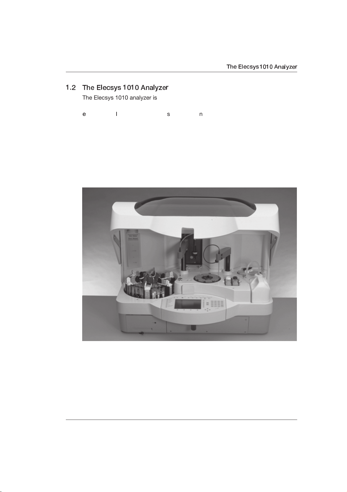
1.2 The Elecsys 1010 Analyzer
The Elecsys 1010 analyzer is a fully automatic, run-oriented analyzer system for
determination of immunological tests using the
e
lectrochemiluminescent process. All components and reagents for routine
analysis are integrated in or on the analyzer.
Operation of the analyzer is simple and intuitive. The reagents are stable and can
be directly loaded onto the analyzer. The consistent use of bar-coded reagents
greatly reduces the need for time-consuming manual entries in the daily routine.
Additional automation can be achieved by connecting a laboratory EDP (host)
system.
ECL/Origen
You can use serum and plasma samples in primary tubes, Hitachi standard cups,
microcups or cups on primary sample tubes. Bar-coded sample tubes are
recognized. Two STAT positions for STAT samples are also available.
Results are produced either qualitatively or quantitatively depending on the test.
The typical test throughput is approximately 50 results per hour.
V 3.0 – Reference Guide 1 - 3
Page 12
Roche Diagnostics Elecsys® 1010 Immunoassay System
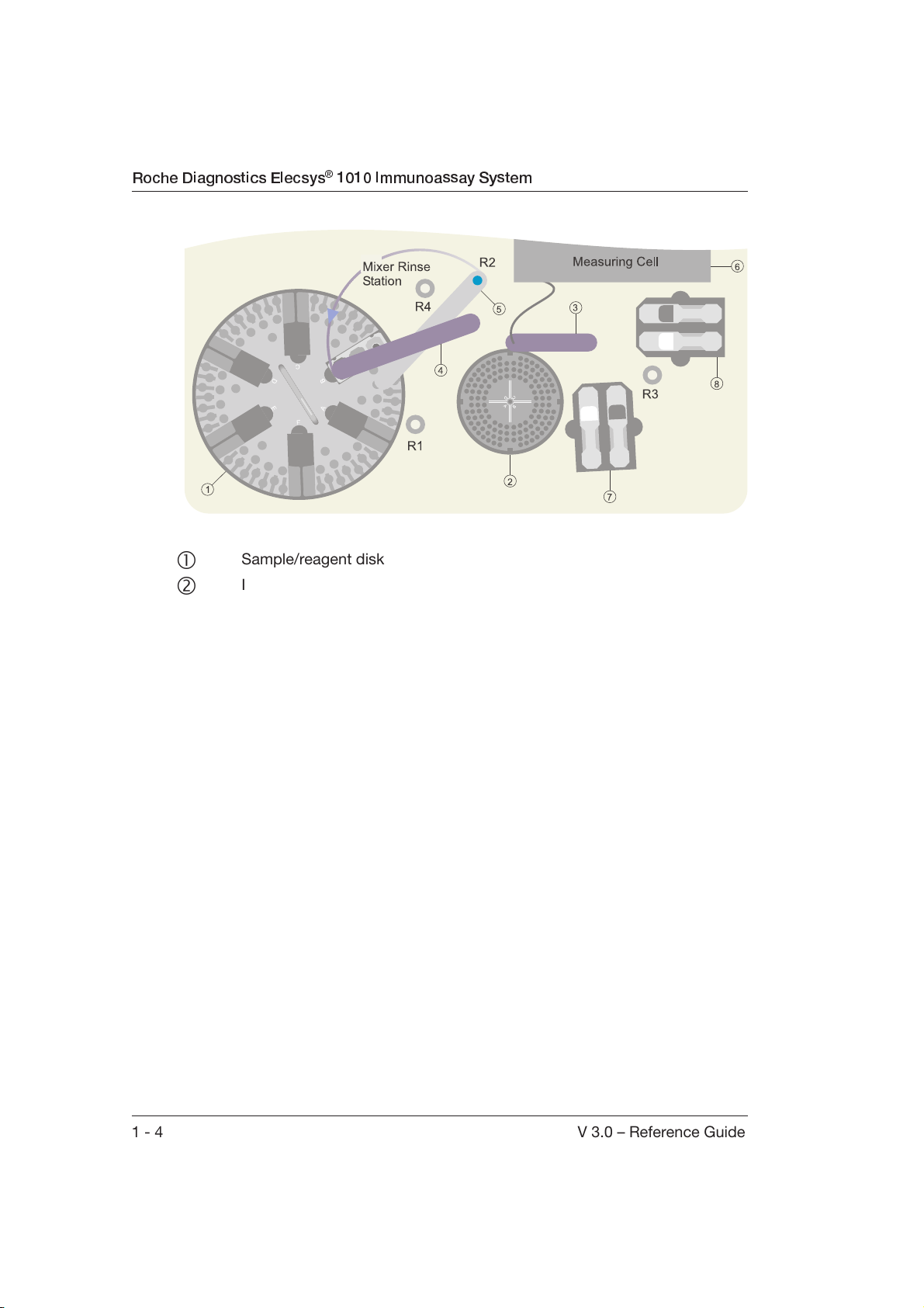
R1/R2 S/R probe rinse station
R3 Sipper probe rinse station
R4 Mixer rinse station
Sample/reagent disk
Incubator
Sipper arm
+ Sample/reagent arm (S/R probe and mixer)
Detection unit (measuring cell)
+ Positions for ProCell and CleanCell bottles
1 - 4 V 3.0 – Reference Guide
Page 13
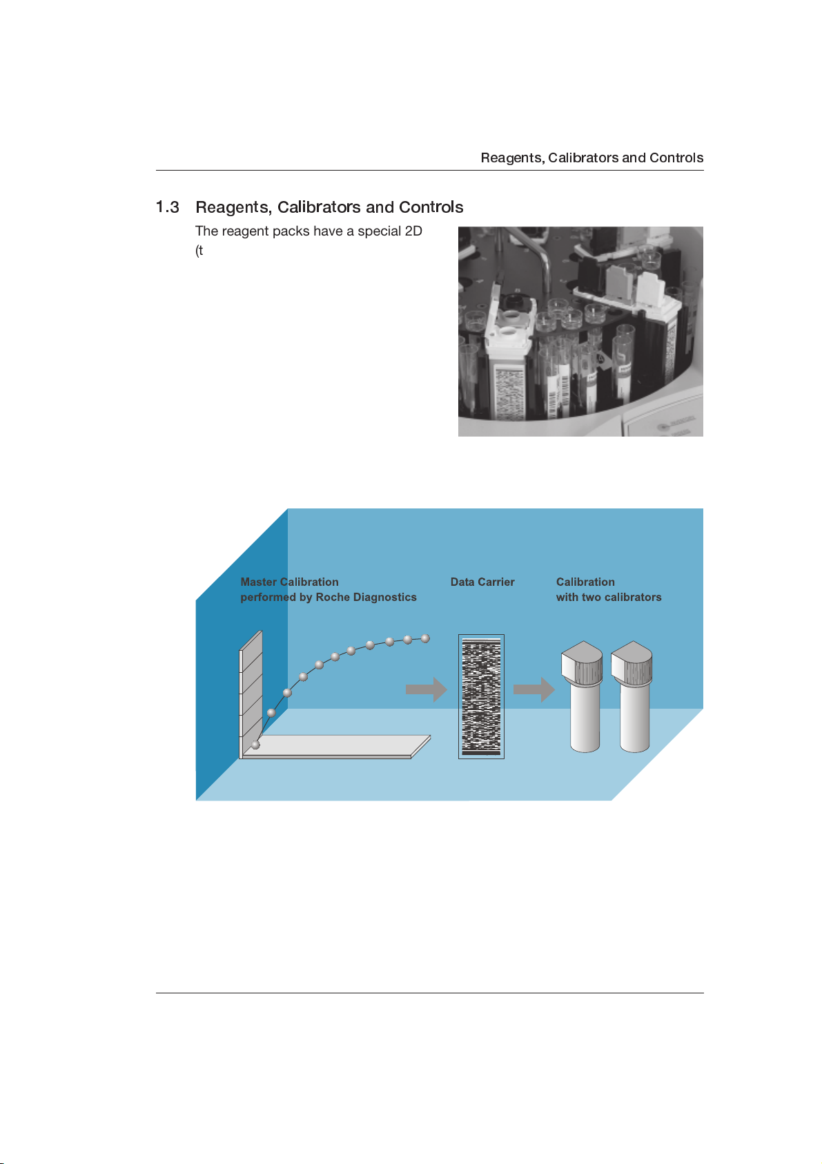
1.3 Reagents, Calibrators and Controls
The reagent packs have a special 2D
(two dimensional) bar code, which
allows fully automatic registration and
management of reagent information.
Manual input or additional monitoring is
not necessary. The ready-to-use, liquid
reagents are loaded into one of the six
positions on the sample/reagent disk.
Reagents are available for analysis
after their bar codes have been
scanned.
Reagents, Calibrators and Controls
The handling of calibrators and Roche Diagnostics controls corresponds to that of
reagents. Most calibrators are ready-to-use. Lyophilized controls and some
calibrators must be prepared and transferred into the appropriate container.
Calibrator and control information is stored on 2D bar code cards (see Chapter
1.3.7, Calibrator and Control Bar Code Cards).
V 3.0 – Reference Guide 1 - 5
Page 14
Roche Diagnostics Elecsys® 1010 Immunoassay System
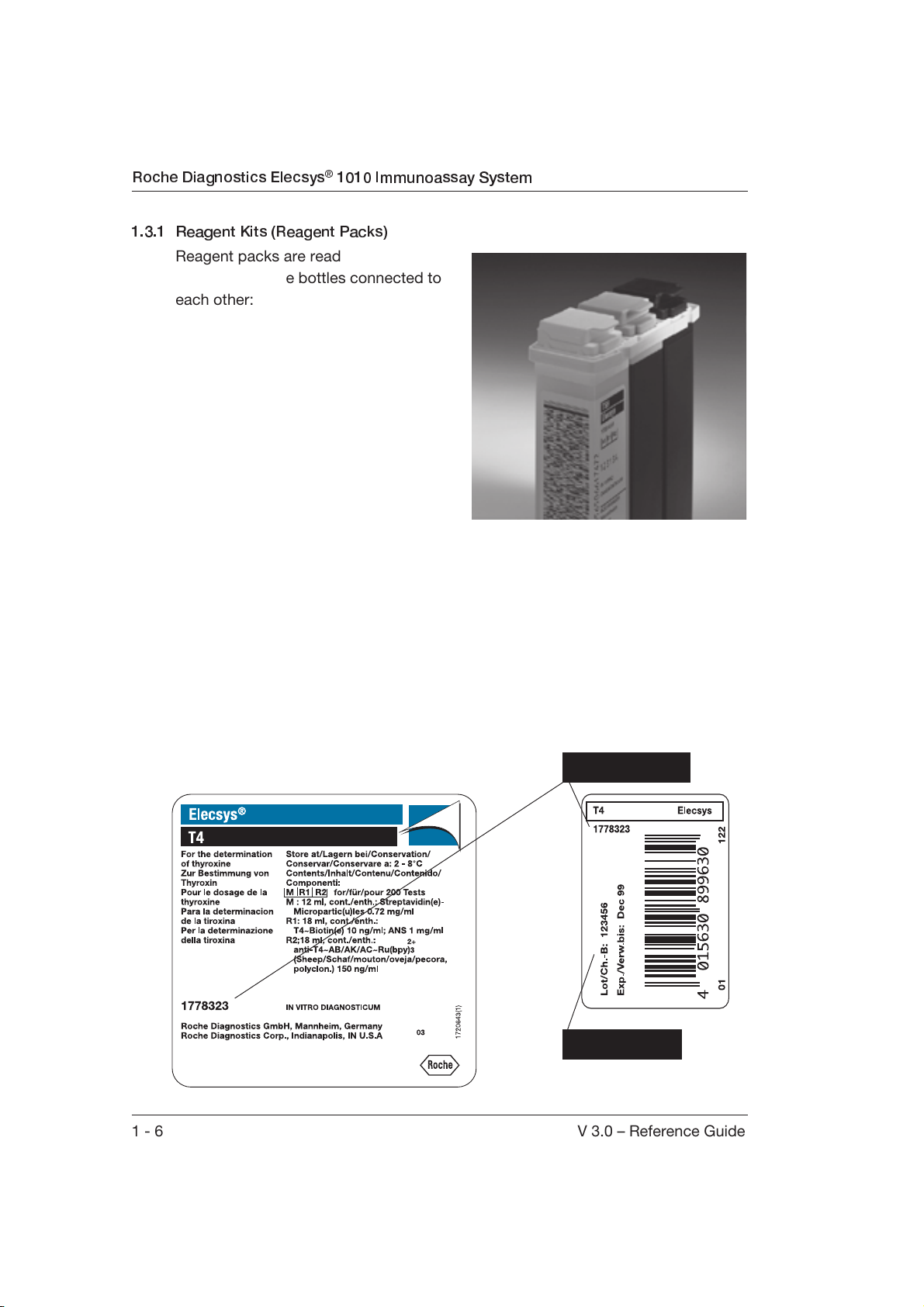
1.3.1 Reagent Kits (Reagent Packs)
Reagent packs are ready-to-use and
incorporate three bottles connected to
each other:
●
The white bottle with a transparent
lid contains suspended magnetic
microparticles that act as the carrier
material of the ruthenium-labeled
complex during measurement.
●
The black bottle with a gray lid
contains R1.
●
The black bottle with a black lid
contains R2.
The test application, calibration data,
control information, sample and reagent volumes, as well as special measurement
conditions are contained in the reagent bar code and therefore do not have to be
entered separately by the operator.
The following are examples of typical box labels for an Elecsys reagent kit. The
large label contains the intended use statement, storage temperature, contents
and catalog number of the kit. The smaller side box label contains the lot and
expiration date of the kit as well as a bar code number. This bar code number is
used for tracking purposes and is not used by the analyzer.
Catalog number
Kit lot number
1 - 6 V 3.0 – Reference Guide
Page 15
Reagents, Calibrators and Controls
1.3.2 Package Insert
Each reagent kit includes a package insert. This insert contains information
required to perform the assay. Detailed information is contained in the product
information sheet supplied separately.
1.3.3 Product Information Sheet
Each assay applied to this analyzer has a product information sheet that provides
general information about the assay. Data contained in the product information
sheets is more detailed than what is in the package insert. Instrument settings are
encoded in reagent bar codes and not entered by the operator. This type of
information, such as sample volume, reagent volume, etc., are found in the
overview section of the product information sheet.
Product information sheets can be obtained from Roche Diagnostics as required.
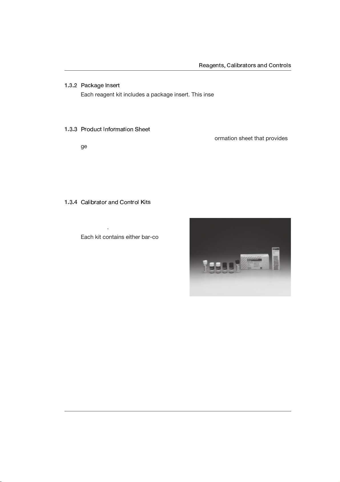
1.3.4 Calibrator and Control Kits
In most cases, calibrators and controls
for Elecsys reagents come packaged
separately.
Each kit contains either bar-coded
calibrator or bar-coded control vials
ready for use on the analyzer. Most
calibrators are in ready-to-use liquid
form and require no further action other
than to place them on the sample/
reagent disk when a calibration is
necessary.
A few of the calibrators and controls
are lyophilized in glass bottles and must be reconstituted before being transferred
into plastic bar coded-labeled vials. (Empty bar coded-labeled vials are packaged
in these kits with lyophilized calibrators and controls.) Reconstituted calibrators
and controls can be stored in the plastic vials after transfer.
Calibrators and controls also have color-coded caps to assist you in identification.
A white cap is a level one calibrator/control and a black cap is a level two
calibrator/control. In the course of the year 2000, black and white color-coded
caps for controls will be phased out in favor of beige/light brown (level one) and
caramel/dark brown (level two).
Calibrator and control bar code cards are packed with calibrator and control kits,
respectively (see Chapter 1.3.7, Calibrator and Control Bar Code Cards).
V 3.0 – Reference Guide 1 - 7
Page 16
Roche Diagnostics Elecsys® 1010 Immunoassay System
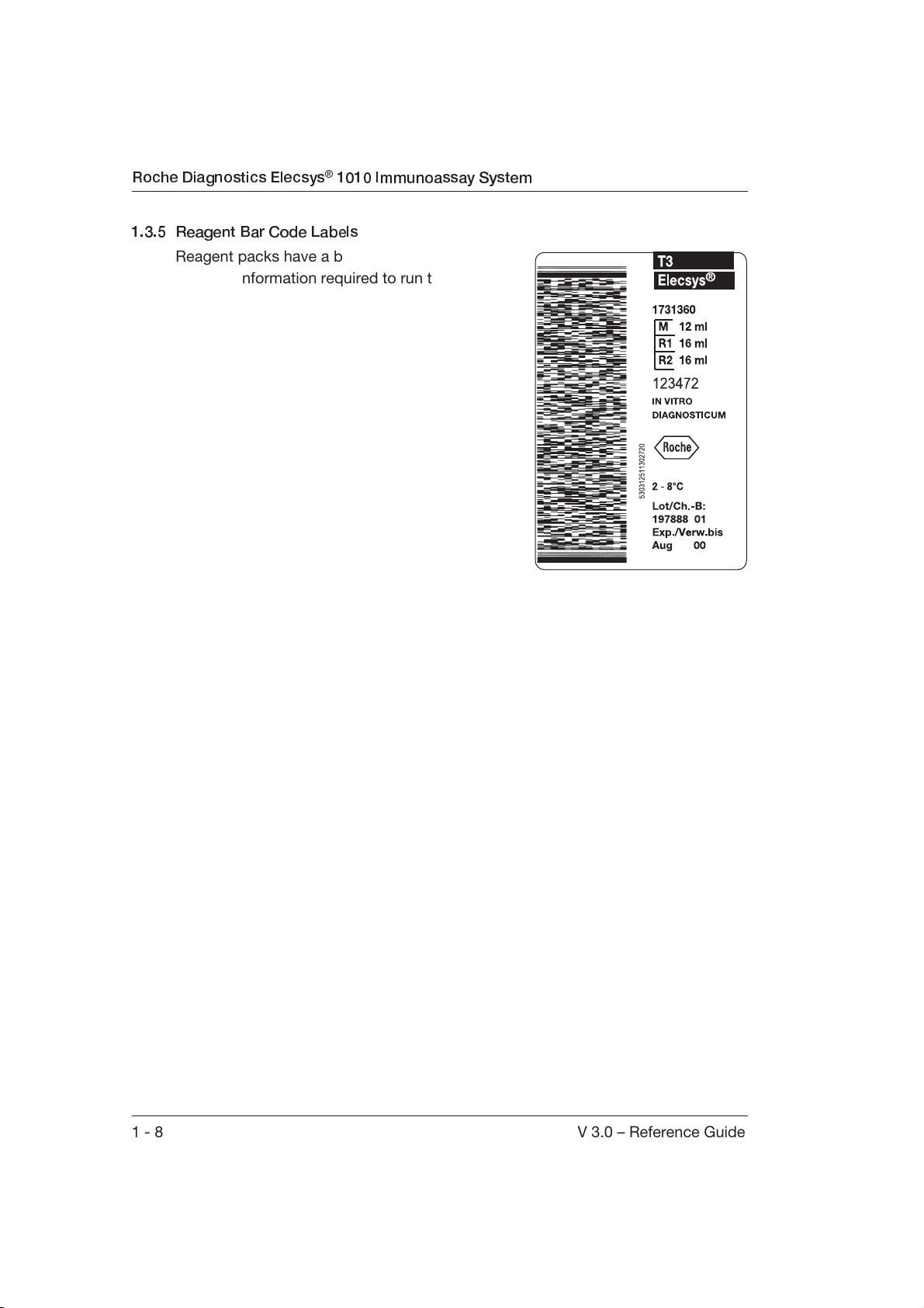
1.3.5 Reagent Bar Code Labels
Reagent packs have a bar code label that
contains information required to run the assay.
This information includes:
●
test number
●
lot number
●
master calibration curve parameters
(e.g. Rodbard parameters)
●
instrument settings
●
calibrator lot numbers and target values
●
expiration date
●
calibration frequency
The following information can be identified on
each reagent bar code label:
kit catalog number
reagent pack number
reagent bar code number
kit lot number
expiration date.
The reagent bar code label is in a new format. The new symbology utilizes
portable data files (PDF) and is called PDF417. Traditional linear bar codes serve
as a link to a database that contains the appropriate information. PDF417 is a two
dimensional (2D), stacked bar code that contains an actual entire data record. The
large amount of data that can be encoded allows all instrument settings to be
included, as well as the master calibration curve and additional information for the
assay. It is from this master curve and from the operator 2-point calibration that
the analyzer derives the update of the master calibration curve. For further
information, refer to Chapter 6, Calibration.
“Every PDF417 symbol (bar code) contains two error detection codewords that are
used like the check digit in linear bar code symbologies to detect decode errors
and verify that all data have been read and decoded accurately. Additionally,
PDF417 provides error correction in the event that portions of symbol have been
damaged, destroyed or are unreadable.”
1
It is a combination of this error detection and error correction that ensures a
reliable bar code. If the bar code cannot be read and the reagent lot has been
previously used by the analyzer, the 15-digit number can be entered manually in
the software.
1. Itkin S, Martell J. A PDF417 Primer: A Guide to Understanding Second Generation Bar Codes
and Portable Data Files. Bohemia, NY: Symbol Technologies, Inc; 1992:17-18.
1 - 8 V 3.0 – Reference Guide
Page 17
Reagents, Calibrators and Controls
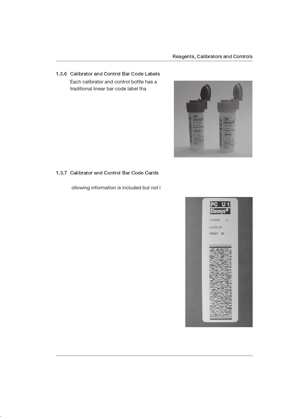
1.3.6 Calibrator and Control Bar Code Labels
Each calibrator and control bottle has a
traditional linear bar code label that
contains an identifier to link it to information
encoded in the reagent bar code label and
the calibrator or the control bar code card
(see Chapters 1.3.5 and 1.3.7).
1.3.7 Calibrator and Control Bar Code Cards
Each calibrator and control kit comes with one or two 2D bar code cards. The
following information is included but not limited to:
●
test number
●
calibrator/control lot number
●
control code (e.g., PCU1) (control card only)
●
lot number of the calibrator/control bar code
label
●
information about which calibrator is to be
used and the number of determinations
(calibrator card only)
●
target values
●
control ranges (control card only)
●
expiration date.
Roche Diagnostics produces a factory master
calibration for each calibration lot. The results
are encoded into the corresponding reagent bar
code. Scan the new bar code card when a new
lot of calibrators or controls is used.
V 3.0 – Reference Guide 1 - 9
Page 18
Roche Diagnostics Elecsys® 1010 Immunoassay System
1.4 Potential Hazards and Safety Precautions
1.4.1 Safety Notes
To protect yourself from potential hazards, you must review all safety precautions
and regulations concerning the handling of materials and the system's electrical
and mechanical components.
The important safety notes in this manual are listed and classified below. Make
yourself acquainted with the following visual cues and icons:
WARNING
$
Warning messages contain information which, if not followed, could cause serious
personal injury and/or damage to the analyzer.
CAUTION
Caution messages contain information which, if not observed, could result in loss
of data and/or damage to the analyzer.
Note
Notes contain important information about a topic in the text.
1 - 10 V 3.0 – Reference Guide
Page 19
Potential Hazards and Safety Precautions
Electricity
To avoid an electric shock DO NOT attempt to open the instrument panels and
work in any electronic compartment.
Chemical
The operator is responsible for taking all necessary precautions against hazard
associated with the use of clinical laboratory chemicals. Specific
recommendations for each reagent used on the analyzer are found on the box
label, package insert or product information sheet for each chemistry. Material
Safety Data Sheets (MSDS) are available for Roche Diagnostics reagents.
Immediately remove any reagent spillage from the instrument.
Mechanical
As with any mechanical system, certain precautions must be taken when
operating the instrument. DO NOT wear loose garments or jewelry that could
catch in moving mechanisms. DO NOT put your hand into the pathway of any
moving parts while the analyzer is operating. Operate the instrument with the
cover down. DO NOT attempt mechanical repairs unless the instrument is in
Stand-by or OFF.
Biohazardous Materials
As with all in vitro diagnostic equipment, patient samples and serum-based quality
control (QC) products that are assayed on this system, as well as all waste from
the waste container, should be treated as potentially biohazardous. All materials
and mechanical components associated with the sampling and waste system
should be handled according to your facility’s biohazard procedure. Use the
personal protective equipment recommended by your facility when handling any of
these components.
V 3.0 – Reference Guide 1 - 11
Page 20
Roche Diagnostics Elecsys® 1010 Immunoassay System
Safety Precautions During Operation
Samples
1. Treat all samples as potential biohazards. If sample spills on the instrument,
use correct personal protective equipment (PPE-gloves, lab coat, etc.) and
wipe off the spillage immediately.
2. Make sure that the sample does not contain any fibrin, dust or other insoluble
contaminants. If insoluble contaminants are contained in the sample, correct
measuring values may not be obtained.
Waste Solution and Solid Wastes
1. Avoid direct contact with waste solution and/or solid wastes. Both should be
handled as potential biohazards.
2. Dispose of waste solution and/or solid wastes according to the relevant
governmental regulations.
3. Consult the reagent manufacturer for information on the concentrations of
heavy metals and other toxic constituents in each reagent.
4. $ WARNING
Do not add bleach to the liquid waste container. Bleach combined
with the contents of the liquid waste could cause potentially harmful
fumes.
Biohazardous Parts
1. Avoid direct contact with the sample/reagent probe, sipper probe and rinse
station. Treat these areas as potentially biohazardous.
Reagents
1. Avoid direct contact with reagents. Direct contact may result in skin irritation
or damage. Refer to the reagent kit box labels or package insert for specific
instructions.
2. Avoid direct contact with CleanCell. Direct contact may result in skin irritation
or damage. Refer to the CleanCell box label or package insert for specific
instructions.
1 - 12 V 3.0 – Reference Guide
Page 21
Potential Hazards and Safety Precautions
Additional Precautions
Flammables
Avoid using dangerous flammables near the instrument. Fire or explosion may be
caused by naked flames.
Accuracy/Precision of Measured Results
For proper use of the instrument, measure control samples and monitor the
instrument during operation.
An incorrectly measured result may lead to an error in diagnosis, therefore posing
a danger to the patient.
Application
The instrument is designed for clinical immunological test analysis using watersoluble samples and reagents.
Please note that other analyses may not be applicable to this instrument.
Operator Qualification
1. Operation should be conducted under the management of a technician who
has undergone training at the facility specified by the sales agent.
2. For clinical tests, the instrument should be used under the management of a
doctor or clinical inspector.
Operation and Maintenance
1. During operation and maintenance of the instrument, proceed according to
the instructions and do not touch any parts of the instrument other than those
specified.
2. Do not open the cover while the analyzer is running or operation will be
stopped.
Installation Requirements
Installation is performed by a Roche Diagnostics representative. The customer is
responsible for providing the necessary facilities as detailed in Section 2.13,
Technical Data.
V 3.0 – Reference Guide 1 - 13
Page 22
Roche Diagnostics Elecsys® 1010 Immunoassay System
Restriction on Samples and Reagent Solutions
1. The assay cups, detection unit and liquid waste container are not guaranteed
to be chemically resistant against organic solvents. Therefore, do not use
organic solvents on these parts.
2. Avoid using samples and reagent solutions that are likely to adhere to the
assay tips, assay cups, liquid waste container or detection unit.
Handling Reagent Solutions
Follow the manufacturer’s instructions for use of reagent solutions.
Loading Samples and Reagents
Be sure to load samples and reagents only into the specified positions on the
instrument.
If sample or reagent is spilled, malfunction of the instrument may occur.
Sample/Reagent Disk
Never load new samples onto the sample/reagent disk during the scan process.
When loading the sample/reagent disk, follow the instructions in the manual.
Microparticle Mixer
Be careful not to bend the microparticle mixer. A bent mixer could lead to
inaccurate results.
Switching On the Instrument
After the analyzer has been switched off, wait approximately 10 seconds before
switching it back on.
Instrument Unused for a Long Time
If the instrument will not be used for a long period of time, contact Technical
Support. Different shutdown procedures are recommended depending upon the
duration of inactivity. In addition, certain procedures require the assistance of a
Roche Diagnostics service representative.
1 - 14 V 3.0 – Reference Guide
Page 23
Potential Hazards and Safety Precautions
1.4.2 Accident Prevention
Elecsys 1010 is a fully automatic analyzer designed according to the most up-todate safety requirements. This ensures the highest possible protection for the
operator from accidents and ensures correct functioning of the system.
Before using the Elecsys 1010, review the safety precautions described in this
chapter to avoid operational interruptions and to protect you from potential
hazards.
The following overview describes specific features for optimal analyzer and
operator protection.
Operator Training
Roche Diagnostics provides system training after which an operator not only
works with the Elecsys 1010 but is also familiar with the relevant safety aspects.
Stand-by Operation and Analyzer Preparation
(Stand-by = the analyzer has power, however, the motion functions of the
individual components are disabled). In Stand-by mode, the tips of the S/R and
sipper probe and the paddle of the microparticle mixer are stowed in their home
positions in the rinse stations. Therefore, the operator cannot be injured by the
probes.
The sample/reagent disk can be removed from the analyzer. Therefore, loading of
samples, reagent packs, calibrators and controls can either be performed on the
analyzer or away from the analyzer.
The consumable containers (CleanCell, ProCell, water and waste containers) are
replaced or refilled in Stand-by mode.
When all the necessary substances have been loaded on the analyzer, the scan
process can be started after closing the cover.
V 3.0 – Reference Guide 1 - 15
Page 24
Roche Diagnostics Elecsys® 1010 Immunoassay System
Analyzer Cover
The analyzer cover must be closed prior to starting a run. A run cannot be started
when the cover is open. If the cover is opened during initialization, the analyzer
stops immediately.
If the cover is opened during a run, the analyzer moves the probes and
microparticle mixer to their home positions in the rinse stations within 2 seconds
to prevent accidental contact. As a result, the run is stopped.
CAUTION
Opening the analyzer cover during a run may cause results to be lost.
STOP
Key
Press the STOP key to stop all operations that Elecsys 1010 is performing as soon
as possible. This process is the same as that described for the analyzer cover.
STAT
Samples
STAT (Short Turn Around Time) samples can be placed on the analyzer in the
designated positions behind the control unit, even when the cover is closed and a
run is being performed. Contact with the probes or microparticle mixer is not
possible. To load STAT samples, the drawer is pulled forward to expose the STAT
positions. There is a mechanical lock present when access is not permitted.
1 - 16 V 3.0 – Reference Guide
Page 25
1.5 Approvals
The Elecsys 1010 analyzer was manufactured and tested according to
international standard IEC 1010-1, “Safety requirements for electrical equipment
for measurement, control and laboratory use, Part 1: General requirements”. This
international standard is equivalent to the national standard Underwriters
Laboratories (UL) 3101-1.
The analyzer was tested and approved by the VDE and UL and received the
following safety marks:
Approvals
C
U
®
U
V
D E
L
L
®
¨
geprufte
Sicherheit
Issued by
Association of German Electrical Engineers (VDE).
Issued by Underwriters Laboratories, Inc. (UL).
Issued by Underwriters Laboratories, Inc. for Canada as
a Certification and Testing Organization by the
Standards Council of Canada (SCC).
The analyzer complies with the European Union (EU)
directive 89/336/EEC (Electromagnetic Compatibility).
VDE Testing and Certification Institute,
V 3.0 – Reference Guide 1 - 17
Page 26
Roche Diagnostics Elecsys® 1010 Immunoassay System
1 - 18 V 3.0 – Reference Guide
Page 27
2. System Description
Control Unit
V 3.0 – Reference Guide 2 - 1
Page 28
Roche Diagnostics Elecsys® 1010 Immunoassay System
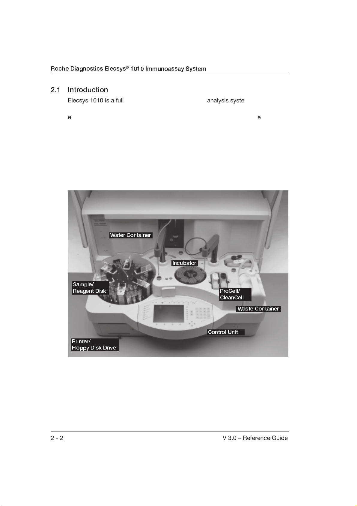
2.1 Introduction
Elecsys 1010 is a fully automated routine and STAT analysis system for the
determination of immunological tests using the ECL/Origen
e
lectrochemiluminescent process. The system measures samples in the form of
serum and plasma. Depending on the test used, the results are produced either
as quantitative or qualitative results.
Elecsys 1010 was designed to be placed on a table. The photograph below
shows where the components for the daily routine are located on the analyzer.
The analyzer has an interface for the connection of a laboratory
An external printer and a PC-compatible keyboard can also be connected.
Water Container
EDP (host) system.
Incubator
Sample/
Reagent Disk
Printer/
Floppy Disk Drive
ProCell/
CleanCell
Waste Container
Control Unit
The system was designed to be powered on and operated 24 hours a day. Power
the analyzer on with the cover down. After configuration run is complete, the
analyzer goes into Stand-by and is ready for operation.
2 - 2 V 3.0 – Reference Guide
Page 29
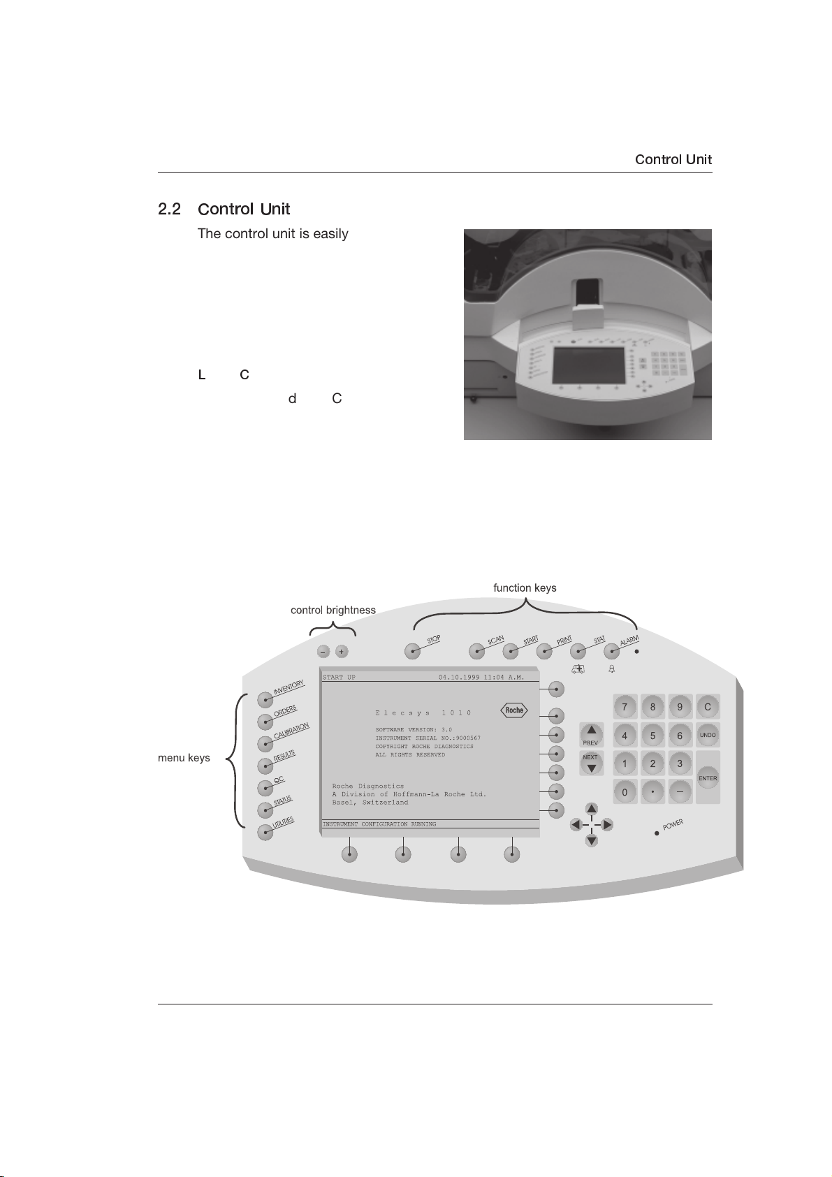
2.2 Control Unit
The control unit is easily accessible from
the front of the analyzer. It is used by the
operator to enter the tasks that the
analyzer is to perform.
The control unit is comprised of a
keyboard, covered by a plastic
protection cover and an
L
iquid Crystal).
Located around the LC display (to the
right and below the display) are
unlabeled keys, called soft keys, which
point to the display. The functions of
these keys change according to the screen displayed.
All keys with a fixed function [to the left (menu keys) and above the display
(function keys)] are labeled accordingly. For example, pressing the SCAN key
initiates a scan of bar code-labeled tubes and reagent packs loaded on the
sample/reagent disk.
LC display (LC =
Control Unit
As an option, a PC-compatible keyboard can be connected for entering text and
special characters. For this purpose, there is a 5-pin standard connector
underneath and to the right of the control unit.
V 3.0 – Reference Guide 2 - 3
Page 30
Roche Diagnostics Elecsys® 1010 Immunoassay System
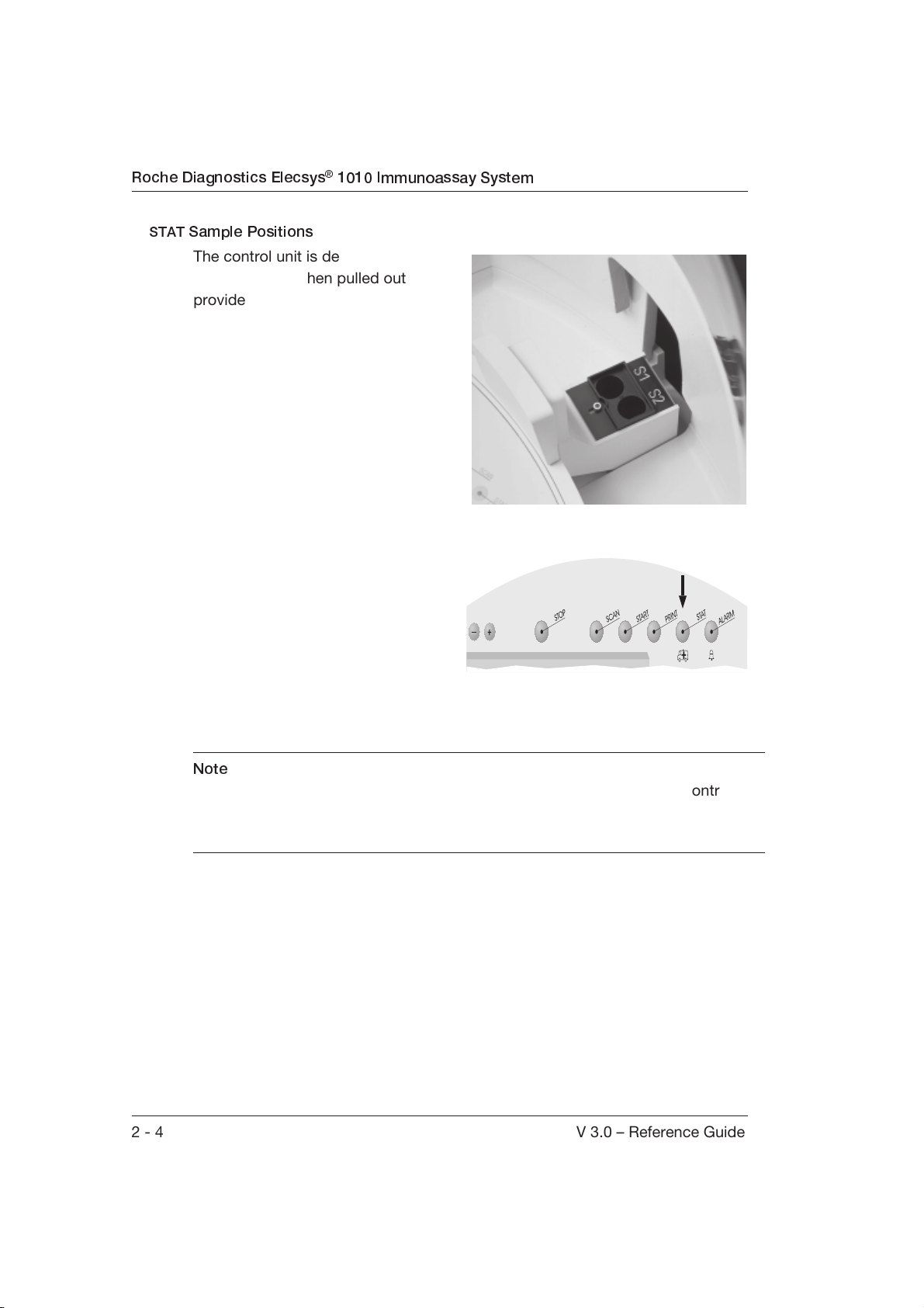
STAT
Sample Positions
The control unit is designed like a
drawer, which when pulled out
provides access to the two STAT
positions. During a run, up to two
STAT samples at a time can be
loaded in primary tubes or when
using a special adapter (supplied) in
secondary cups.
Normally, access to both STAT
positions is always possible. When
the STAT key is pressed, the
requests for one or both STAT
samples can be entered.
When the STAT requests have been
confirmed, the control unit is locked into
position by the analyzer until all of the
requested tests have been pipetted.
The control unit is then immediately
unlocked so that further STAT samples
can be processed during a run.
Note
A power failure during the pipetting of the STAT samples may lock the control
unit. The locking device can be temporarily overridden by inserting a screwdriver
below the control unit.
2 - 4 V 3.0 – Reference Guide
Page 31

Sample/Reagent Disk
2.3 Sample/Reagent Disk
Patient samples, reagents, diluents,
calibrators and controls required for a
run are loaded on the sample/reagent
disk.
During a run, the disk positions the
sample containers so that they can be
reached by the S/R probe and the
microparticle mixer.
Reagent Positions
The disk has six positions laid out in
the form of a star. These positions are
used to load six reagent packs for use in a run. The reagent pack positions are
labeled from A to F.
Sample, Calibrator and Control Positions
The sample/reagent disk has 66 numbered positions for patient samples,
calibrators and controls. The positions 1 to 42 are scanned by the bar code reader
and can be loaded, for example, with bar code-labeled primary tubes. The
positions 43 to 66 are intended for secondary cups (e.g., Hitachi standard cups).
The bar code positions can be converted into 36 secondary cup positions by
using six adapters. This is useful in laboratories that do not want to use primary
tubes on Elecsys 1010.
V 3.0 – Reference Guide 2 - 5
Page 32

Roche Diagnostics Elecsys® 1010 Immunoassay System
Bar Code Card Holder
At each reagent pack position, there is
a slot for inserting a bar code card for
calibrators and controls.
The control or calibrator 2D bar code
cards contained in the packaging is
inserted in an available bar code card
slot and is scanned by the bar code
scanner (SCAN key).
2 - 6 V 3.0 – Reference Guide
Page 33

Sample/Reagent Arm
2.4 Sample/Reagent Arm
The sample/reagent (S/R) arm is
located between the sample/reagent
disk and the incubator. On one side
there is the sample/reagent (S/R) probe
and on the other side, the microparticle
mixer. During a run the S/R arm moves
the mixer or S/R probe to the
appropriate pipetting, mixing or rinsing
position.
Sample/ Reagent Probe
The S/R probe transfers sample,
reagent and microparticles into the
assay cups in the incubator.
The S/R probe has an automatic liquid detection system (
D
etection) that can detect whether or not there is liquid present. The probe
detects the liquid surface when it is lowered into the container. This prevents air
from being pipetted when there is insufficient liquid available.
An abnormal descent sensor stops further probe movement when the bottom of
the container is detected. This sensor also prevents the probe from being
damaged when a reagent pack has not been opened.
Possible clot formation is recognized by a pressure sensor in the S/R pipetting
system (clot detection).
LLD =
L
iquid Level
Mixer
At regular intervals, the mixer resuspends the microparticles contained in every
reagent pack that are required for analysis.
V 3.0 – Reference Guide 2 - 7
Page 34

Roche Diagnostics Elecsys® 1010 Immunoassay System
Rinse Stations
The rinse stations W1 and W2 are used to clean or rinse the S/R probe. A cleaning
or rinsing process is performed between the individual aspirations of the liquids
(sample, reagent and microparticles).
The mixer has a separate rinse station. The mixer is cleaned before and after
resuspension of the microparticles.
Mixer Rinse
Station
W2 S/R Probe
Rinse Station
W1
2 - 8 V 3.0 – Reference Guide
Page 35

2.5 Incubator
The immunochemical reaction is
performed in assay cups located in the
incubator. The temperature of the
incubator is maintained at a constant
37 °C (±0.3 °C).
Assay Cups
The reaction of sample, reagent and
microparticles takes place in the assay
cups. The incubator can hold four preloaded segments containing assay
cups. These segments are loaded into
the positions labeled A through D. Each segment can hold 32 assay cups, thus
the maximum number of assay cups is 128 (four segments each with 32
positions).
The Incubator
Assay Cup Segments
The pre-loaded segments can be easily
placed into and removed from the
analyzer.
The operator must remove used
segments and reload with new
segments before or after each run.
The photosensor does not detect the
presence or absence of individual
cups. Removal and replacement of
individual cups will lead to erroneous
results. ReSegments in which all the
assay cups have been used must be replaced. Partially used segments can
remain in the incubator until all 32 assay cups have been used. The
screen can be used to display the status of each assay cup.
INVENTORY
V 3.0 – Reference Guide 2 - 9
Page 36

Roche Diagnostics Elecsys® 1010 Immunoassay System
2.6 Sipper Arm
The sipper probe, located on the sipper
arm, transports the reaction mixture
from the assay cups to the measuring
cell. It also transports CleanCell and
ProCell to the measuring cell. The
sipper arm can reach all assay cups
loaded in the incubator as well as both
sets of CleanCell and ProCell.
Sipper Probe
The sipper probe has an automatic
liquid detection system (
L
evel Detection) that can detect
LLD =
L
iquid
whether or not there is liquid in an
assay cup. The probe detects the liquid
surface when it is lowered into a
ProCell or CleanCell bottle. This
prevents air from being pipetted when there is insufficient liquid available.
An abnormal descent sensor prevents the probe from hitting the bottom of an
assay cup to avoid damage to the probe and to ensure correct aspiration of the
reaction mixture. This sensor also prevents the probe from being damaged when
a ProCell/CleanCell bottle has not been opened by the operator.
Sipper Probe
Rinse Station
ProCell/
CleanCell Set 2
ProCell/
CleanCell Set 1
Rinse Station
The sipper probe is cleaned in its own rinse station after each pipetting process.
2 - 10 V 3.0 – Reference Guide
Page 37

2.7 Liquid System
The liquid system transports sample, reagent, microparticles, CleanCell, ProCell,
diluent and distilled water, as well as liquid waste. The components that can be
seen by the operator are the pipettors, the tube connections and the containers
for distilled water and waste.
Pipettors
Two pipettors, as well as several
pumps (behind the housing cover)
transport the liquids. The left pipettor is
responsible for aspirating and
dispensing liquids for the S/R probe
and the right pipettor controls liquid
transportation through the sipper and
detection unit.
L
iquid System
Distilled Water Container
The distilled water container is located
on the left of the analyzer. It can hold
up to 4 liters of distilled water. The
container can be easily removed
before and after every run in order to
refill it.
Note
Use caution when removing or
replacing the distilled water container
to ensure no water drips onto the S/R
disk.
V 3.0 – Reference Guide 2 - 11
Page 38

Roche Diagnostics Elecsys® 1010 Immunoassay System
ProCell and CleanCell
The analyzer has two bottles
containing the system reagent ProCell
Set 2
(white caps) and two bottles containing
the system reagent CleanCell (black
ProCell
caps). ProCell is the buffer solution
required by the measuring cell for the
ECL reaction. CleanCell is used to clean
the measuring cell.
The compartments where the bottles
are located are maintained at a
ProCell
CleanCell
Set 1
temperature of 28 °C to prevent
temperature fluctuations in the
measuring cell (also maintained at
28 °C).
One bottle of ProCell and one bottle of
CleanCell forms a set. As soon as a set
is empty, the other set is used. An empty set should be replaced by two new
bottles before or after a run.
CleanCell
Waste Container
Waste Container
The entire waste liquid is pumped into the waste container located on the right
side of the analyzer. The waste container can hold approximately 5.5 liters of
waste and can be easily removed and replaced before and after each run to
empty it.
2 - 12 V 3.0 – Reference Guide
Page 39

2.8 Measuring Cell
The measuring cell is the core of the system. It is located in a light-proof capsule
in a housing behind the sipper arm and the temperature is precisely controlled at
28 °C (±0.3 °C). The measurement signals produced are used by the Elecsys
1010 to calculate the results.
The measuring cell is a sealed chamber and consists of a working electrode,
counter electrodes, a magnet and a photomultiplier.
Measuring Cell
V 3.0 – Reference Guide 2 - 13
Page 40

Roche Diagnostics Elecsys® 1010 Immunoassay System
When the reaction mixture, consisting of sample and reagent, is placed in the
measuring cell, three processes are performed to produce the measurement
signals:
Bound/Free Separation
Using a magnet, the streptavidin microparticles coated with antigen-antibody
complexes are uniformly deposited on a defined spot of the working electrode.
They remain there for the entire measurement period. For a few seconds, a buffer
solution (ProCell) is flushed through the measuring cell to wash the microparticles
on the working electrode and to flush out excess reagent and sample material.
ECL
Reaction
A voltage is applied to the working electrode to initiate the ECL reaction. The light
emission, produced by the complex radical reaction, is measured by a
photomultiplier. These signals are used by the system to calculate the results.
Releasing the Microparticles and Cleaning the Cell
Once the measurement is complete, the measuring cell is reconditioned with a
special cleaning solution (CleanCell) and is ready for a new measurement.
A detailed description of the ECL reaction can be found in Chapter 4, ECL
Technology.
2 - 14 V 3.0 – Reference Guide
Page 41

2.9 Power Switch
The ON/OFF switch is located on the
left of the analyzer. This switch applies
voltage to the main power supply (110
to 240 VAC).
2.10 Printer
A thermal printer is located at the front
left of the analyzer behind a door.
All results and the most of the
displayed screen information can be
printed out. To replace the paper, the
door can be opened.
Power Switch
Additionally, a standard parallel
interface enables the connection of an
external printer (Epson or HP
compatible).
V 3.0 – Reference Guide 2 - 15
Page 42

Roche Diagnostics Elecsys® 1010 Immunoassay System
2.11 Floppy Disk Drive
The floppy disk drive is located at the front left of the analyzer next to the thermal
printer.
The disk drive can be used to archive data (i.e., store results) and read reference
data into the system. To insert or remove a disk, simply open the door to access
the disk drive.
2 - 16 V 3.0 – Reference Guide
Page 43

2.12 Interfaces
Elecsys 1010 can be connected to a laboratory EDP (host) system to transfer
information. An external printer and an external keyboard can also be connected.
There are three connections for these purposes.
Printer Connection (Parallel Interface)
To the left of the analyzer, there is a
parallel interface connection for an
optional external printer (Epson or HP
compatible). This printer can be used
instead of the internal printer for
printing results. The printer type is set
in
UTILITIES (INTERFACE SETUP screen).
Refer to the relevant printer
documentation to see how the
connected printer operates.
Printer connection
Host connection
Interfaces
Host Connection (Serial Interface)
To the left of the analyzer, below the printer connection, there is a bidirectional
serial interface connection for a laboratory EDP (host) system. The host
specifications must be set in UTILITIES (INTERFACE SETUP screen and INSTRUMENT
screen).
SETUP
External Keyboard Connection
To the right of the control unit, there is
a connection for an optional standard
PC keyboard. The keyboard can be
used to enter text and special
characters which are not possible with
the control unit keyboard. Once the
external keyboard is connected, no
further settings are required. Both
keyboards can be used together. The
External keyboard
connection
keys on the external keyboard that can
be used for specific functions are
specified in Chapter 1, Introduction.
V 3.0 – Reference Guide 2 - 17
Page 44

Roche Diagnostics Elecsys® 1010 Immunoassay System
2.13 Technical Data
Analyzer Dimensions
Height 24.68 in (62 cm)
Depth 31.04 in (78 cm)
Width 38.21 in (96 cm)
Weight Approx. 243 pounds (110 kg) empty
Electrical Connection
Installation requirements Pollution degree: 2 (IEC 1010-1)
Overvoltage category II (IEC 664)
Elecsys 1010 should only be connected to
a grounded power supply.
Voltage 110-240 VAC ± 10%, single phase
Frequency 50/60 Hz
Power consumption Max. 610 VA
Heat generation Approx. 1800 kJ/h
Environmental Conditions
Temperature 18 °C to 32 °C (during run),
15 °C to 35 °C (in Stand-by mode),
-25 °C to +70 °C (for transportation)
Temperature variation ≤ 3 °C (during run)
≤ 5 °C (in Stand-by mode)
20 K/h (for transportation)
Relative humidity 20% to 85% without condensation (during
run and in Stand-by mode)
10% to 90% (for transportation)
Atmospheric pressure 70 to 106 kPa (2200 m during run and in
(height above sea level) Stand-by mode),
4300 m (for transportation)
2 - 18 V 3.0 – Reference Guide
Page 45

Noise level (DIN 43635)
Continuous noise Max. 60 dBA
Peak noise Max. 65 dBA
Water Supply
Water container Approx. 4 L
Water quality < 10 µS/cm or > 0.1 megohm, bacteria-
free
Water consumption Approx. 2.8 L for 100 tests
L
iquid waste
Liquid waste container Approx. 5.5 L
(can be cleaned in a dishwasher)
Throughput
Determinations Typically 50/h, max. 60/h
(tests with pretreatment and dilution
reduce the throughput by approx. 50%)
Technical Data
Samples
Sample/ Reagent pipettor < 1.5% CV at 10 µL
precision <1% CV at 50 µL
Sample volume per test 10 µL to 50 µL
Sample detection Liquid level detection of S/R probe
Positions on sample/ 42 positions for primary tubes or
reagent disk for samples, 36 positions with secondary cups
adapters,
calibrators and controls 24 positions for secondary cups,
2 additional positions for STAT samples
Sample bar codes NW7 (Codabar), Code 39, Code 128,
Interleaved 2 of 5
V 3.0 – Reference Guide 2 - 19
Page 46

Roche Diagnostics Elecsys® 1010 Immunoassay System
Sample Cups
Primary Tubes
Type Volume
(mL)
SARSTEDT MONOVETTE
SARSTEDT MONOVETTE
SARSTEDT SERUM-GEL
MONOVETTE
BECTON DICKENSON
SST 3206
BECTON DICKENSON
VACUTAINER + GEL SST
3202
BECTON DICKENSON
VACUTAINER + GEL SST
3200
TERUMO VENOJECT II
TERUMO VENOJECT II
10.0 16.5 92 500
4 15.3 57 500
9.0 16.5 92 500
5.0 13.0 75 300
10.0 16.0 75 400
10.0 16.0 100 400
5.0 13.25 100 300
10.0 15.65 100 500
External
Diameter
(mm)
Height
(mm)
Dead
Volume
(µL)
SEKISUI Primary cup 10.0 16.2 100 500
SEKISUI Primary cup 7.0 14.0 100 500
2 - 20 V 3.0 – Reference Guide
Page 47

Secondary Cups
Technical Data
Type Dead
Note
Volume
(µL)
HITACHI Sample Cup
in secondary positions
60 The sample volume may not be less than
or equal to 60 µL.
(42-66)
HITACHI Sample Cup
60
in secondary adapter
HITACHI Micro Cup
in secondary positions
30 The sample volume may not be less than
or equal to 30 µL.
(42-66)
HITACHI Micro Cup
30
in secondary adapter
Secondary or pour-off
280
tube, 16 mm X 100 mm
Secondary or pour-off
235
tube, 13 mm X 75 mm
Others It is recommended that secondary cups other than
those specified here be checked before they are used
on the analyzer. The operator must ensure that there is
sufficient sample in the cup.
C
up on Tube (COT)
Type Dead Volume
(µL)
HITACHI Sample Cup
Cup on Tube 16x95, COT Parameter
50
V 3.0 – Reference Guide 2 - 21
Page 48

Roche Diagnostics Elecsys® 1010 Immunoassay System
Special cups
Dead Volume
(µL)
Control / calibrator vials 80
Reagents
Reagent capacity 6 reagent positions
Reagent detection Liquid level detection by S/R probe
Bottle volume of ProCell and
CleanCell 380 mL
Reagent ID 2D bar code, PDF 417
Incubator
Incubator capacity 128 assay cups
Volume of assay cups typically 200 µL, max. 400 µL
Incubation temperature 37 °C ± 0.3 °C
Incubation period 9/18 minutes
Measurement System
Measurement method Integral measurement of an
electrochemiluminescent signal
Calibration mode 2-point calibration
2 - 22 V 3.0 – Reference Guide
Page 49

PC
Processor 486 X
Floppy disk 3.5 FD/1.44 MB
Interfaces
Printer Centronics
HOST computer CCITT V.24/RS-232-C (bidirectional)
The host computer must comply with the
requirements of IEC 950
LCD S/W VGA - LCD with 640 x 480 pixels
Thermal Printer Paper width 110 mm
V 3.0 – Reference Guide 2 - 23
Page 50

Roche Diagnostics Elecsys® 1010 Immunoassay System
2 - 24 V 3.0 – Reference Guide
Page 51

3. Functional Sequence of Analysis
Übersicht
V 3.0 – Reference Guide 3 - 1
Page 52

Roche Diagnostics Elecsys® 1010 Immunoassay System
3.1 Introduction
The basic functional sequence of the system is detailed in this chapter using a
flow chart and a short description. An overview of the sequence of events for each
test protocol is graphically displayed. A detailed description using the test TSH as
an example provides insight into how the Elecsys 1010 operates.
3 - 2 V 3.0 – Reference Guide
Page 53

Flow Chart of the Analysis Sequence
Introduction
V 3.0 – Reference Guide 3 - 3
Page 54

Roche Diagnostics Elecsys® 1010 Immunoassay System
3.2 General Analysis Sequence
An immunological ECL test is made up of various pipetting steps, at least one
incubation period and a measurement step. Generally, at least three test
components (sample, reagent and microparticles) are pipetted into an assay cup.
After the appropriate incubation period, the reaction mixture is aspirated into the
measuring cell where the measurement process takes place. Each of these
pipetting cycles is performed within a defined period (approximately 60 seconds).
The number of pipetting steps and assay cups used, as well as the make up of
the reaction mixture, are dependent on the test method (refer to Chapter 3.3, Test
Sequences).
After each pipetting step, the sample/reagent probe is cleaned and, if necessary,
the microparticle mixer and sipper probe are also cleaned.
The following steps apply in principal to all methods. The sequence of the
individual processes differs from test to test.
Resuspension of the Microparticles
During this step the microparticles are resuspended by the mixer on the sample/
reagent arm at the beginning of a new run. Resuspension takes place before the
microparticle suspension is aspirated. At the same time, the S/R probe is
thoroughly cleaned. After resuspension, the mixer is cleaned with water in its
special rinse station.
Pipetting of at Least Two Liquids (e.g. Reagent 1 and Sample)
At the beginning of a run, at least one reagent and the sample or microparticles
are aspirated one after the other by the S/R probe. After each aspiration of a
liquid, the outside of the S/R probe is quickly rinsed at a rinse station. Afterwards,
all liquids are dispensed into an unused assay cup. The inside and outside of the
probe is then thoroughly cleaned again.
3 - 4 V 3.0 – Reference Guide
Page 55

General Analysis Sequence
First Incubation at 37 °C
The incubation period is 4.5 or 9 minutes, depending on the test. Tests without
pretreatment have two incubation periods, whereas tests with pretreatment
require additional incubation periods.
Pipetting of Additional Reagents (e.g. Reagent 2 and Microparticles)
In the second pipetting step, one or two liquids are pipetted (refer to Scan be
selected using the arrow keys Chapter 3.3, Test Sequences). The outside of the S/
R probe is rinsed at the rinse station after every aspiration of a liquid. The liquid is
then dispensed into an assay cup that contains the sample and the other liquids
from the first pipetting process.
Second Incubation at 37 °C
If necessary, a second incubation period of 4.5 or 9 minutes occurs, depending
on the test.
Additional Reagent Pipetting (Pretreatment assays)
For pretreatment assays, reagent pipetting similar to that described above for
“Pipetting of Additional Reagents” occurs.
Third Incubation at 37 °C
If necessary, a third incubation step (9 min) occurs for pretreatment assays.
Reaction Mixture Aspiration and Measurement
In this process, the sipper probe first aspirates ProCell to prepare the measuring
cell. Then, the sipper probe aspirates the reaction mixture and transfers it to the
measuring cell. After the sipper probe is washed at the rinse station and ProCell is
aspirated again, the ECL reaction can take place in the measuring cell.
Measuring Cell Cleaning and Results
Once the measurement is complete, the measuring cell is cleaned with CleanCell
and prepared for a new measurement process. At the same time, Elecsys 1010
calculates the results according to the measured signals.
V 3.0 – Reference Guide 3 - 5
Page 56

Roche Diagnostics Elecsys® 1010 Immunoassay System
3.3 Test Sequences
Legend
0 to 29 Test protocols
Test analysis steps
Diluent pipetting
Reagent 1 pipetting
Reagent 2 pipetting
Pretreatment reagent pipetting
Diluted sample pipetting once
Diluted sample pipetting twice
Symbols
Microparticle pipetting
Sample pipetting
Pretreatment
First incubation
Second incubation
Measurement
Addition of
Result of the addition
Transfer
New assay cup
3 - 6 V 3.0 – Reference Guide
Page 57

3.3.1 Test protocol
Test Sequences
V 3.0 – Reference Guide 3 - 7
Page 58

Roche Diagnostics Elecsys® 1010 Immunoassay System
3.4 Example of an Analysis Process
The following describes an analysis process on Elecsys 1010 using the test TSH
as an example. Test protocol number 2, used for the TSH test, is described in this
example (refer to the table on page 3-7).
In this example, sample position number 8 (bar code readable) is used and the
TSH reagent pack is loaded in position B. All positions on the sample/reagent disk
theoretically can be freely chosen for samples as well as reagent packs. The
system automatically recognizes the positions loaded with reagents and barcoded primary tubes due to the presence of a bar code. Samples in non-barcoded primary tubes or secondary cups (43-66) must be manually assigned a
position number.
There are four assay cup segments that can be loaded before the run. Elecsys
1010 uses the next unused assay cup for the first pipetting process. The position
of this cup is stored after it is initially used so that, if necessary, the relevant liquid
(e.g. Reagent 2) is pipetted into this assay cup during the second pipetting
process.
The diagrams below show the sample/reagent disk (S/R disk) and the incubator,
respectively.
Sample / Reagent disk
3 - 8 V 3.0 – Reference Guide
Page 59

Example of an Analysis Process
Incubator
The sample/reagent arm, with the S/R probe on one side and the microparticle
mixer on the other, can reach each of the 66 positions on the S/R disk and the
two STAT positions.
Each of the 128 incubator positions can be reached by the S/R probe as well as
the sipper probe.
V 3.0 – Reference Guide 3 - 9
Page 60

Roche Diagnostics Elecsys® 1010 Immunoassay System
3.4.1 Reagent 1, Reagent 2 and Sample Pipetting
The sample/reagent disk and the sample/reagent arm rotate in such a way that
the probe can reach the TSH reagent pack. While the S/R arm is rotating to the S/
R disk, 50 µL of air are aspirated into the S/R probe to form an air buffer between
the water in the liquid system and the liquids to be aspirated in the following
steps.
When the S/R arm has reached the TSH reagent pack, the probe is lowered into
the TSH reagent pack containing Reagent 1 until the probe has reached the liquid
surface, then 60 µL of Reagent 1 are aspirated.
To prevent carryover of Reagent 1, the outside of the probe is quickly cleaned.
The arm rotates to rinse station 1, the front rinse station for the S/R probe, and is
lowered for cleaning. In the meantime, the S/R disk has rotated so that the S/R
probe can reach the bottle containing Reagent 2.
3 - 10 V 3.0 – Reference Guide
Page 61

Example of an Analysis Process
The arm rotates out of the rinse station and back to the S/R disk. The S/R probe
aspirates 50 µL of Reagent 2.
V 3.0 – Reference Guide 3 - 11
Page 62

Roche Diagnostics Elecsys® 1010 Immunoassay System
The arm then returns to rinse station 1 where the S/R probe is cleaned again. At
the same time, the S/R disk rotates so that the probe can reach the necessary
sample cup. In this example, this is the sample cup at position number 8. After the
S/R arm has rotated back, it is lowered over position 8 until the probe reaches the
liquid surface. The probe aspirates 50 µL of sample. During aspiration, the probe
tip is kept just below the falling liquid level. Additionally, a check occurs to detect
whether clots have formed in the sample container. This clot detection check is
performed during every sample aspiration.
3 - 12 V 3.0 – Reference Guide
Page 63

Example of an Analysis Process
3.4.2 First Incubation
The probe now contains Reagent 1, Reagent 2 and sample. Next, the S/R arm
rotates to the incubator.
The probe dispenses the liquids in the next, unused assay cup.
The reaction mixture is incubated at 37 °C for 9 minutes. In the meantime, other
samples/tests can be processed.
After the liquids have been dispensed into an assay cup, the S/R arm rotates to
rinse station 2 and the inside and outside of the S/R probe are thoroughly
cleaned.
V 3.0 – Reference Guide 3 - 13
Page 64

Roche Diagnostics Elecsys® 1010 Immunoassay System
3.4.3 Resuspension of the Microparticles
While the S/R arm is rotating to rinse station 2, the microparticle mixer rotates to
the S/R disk so that the mixer can be lowered into the TSH reagent pack bottle
containing the microparticles. The S/R disk has already rotated to the correct
position.
At the same time as the S/R probe is being cleaned at rinse station 2, the
microparticle mixer starts to mix (resuspend) the microparticles. This process
takes place before each pipetting of the microparticles.
3 - 14 V 3.0 – Reference Guide
Page 65

Example of an Analysis Process
3.4.4 Microparticle Pipetting
After the resuspension of the microparticles and the thorough cleaning of the S/R
probe at rinse station 2, the S/R arm and the S/R disk rotate in such a way that
the probe can reach the bottle containing the microparticles.
On reaching the TSH reagent pack, the probe aspirates 40 µL of the microparticle
suspension. During the aspiration process, the automatic LLD check occurs.
Afterwards, the arm rotates to the incubator.
The probe now contains the microparticles. The incubator rotates so that the S/R
arm can reach the assay cup that contains the reaction mixture, Reagent 1,
Reagent 2 and sample, from the first pipettor step. The probe dispenses the
microparticles into the assay cup.
V 3.0 – Reference Guide 3 - 15
Page 66

Roche Diagnostics Elecsys® 1010 Immunoassay System
3.4.5 Second Incubation
The liquid mixture is again incubated at 37 °C for 9 minutes (Second incubation).
During this period, other samples/tests can be processed.
3 - 16 V 3.0 – Reference Guide
Page 67

Example of an Analysis Process
3.4.6 Measurement Stage
Before the reaction mixture is transferred to the measuring cell, the measuring cell
is pretreated with ProCell.
The sipper arm rotates to the bottle containing ProCell and the probe aspirates
ProCell. In this example, this is the ProCell and CleanCell Set 2 location. The
liquid is drawn through to the measuring cell.
Note
One ProCell and one CleanCell bottle form a set. The volumes of both bottles are
matched to one another. If a set is empty, the system automatically uses the
second set.
V 3.0 – Reference Guide 3 - 17
Page 68

Roche Diagnostics Elecsys® 1010 Immunoassay System
The sipper arm and incubator rotate towards one another so that the sipper probe
can reach the cup containing the TSH reaction mixture.
The arm is lowered and the sipper probe aspirates 130 µL of the reaction mixture;
the liquid is transferred to the measuring cell. The sipper arm then rotates to the
separate rinse station for the sipper probe and is lowered. The probe is quickly
cleaned from the outside.
3 - 18 V 3.0 – Reference Guide
Page 69

Example of an Analysis Process
The arm rotates to the bottle containing ProCell and the sipper probe aspirates
ProCell. In this example, this is Set 2. The liquid is drawn through to the
measuring cell.
V 3.0 – Reference Guide 3 - 19
Page 70

Roche Diagnostics Elecsys® 1010 Immunoassay System
3.4.7 Measurement and Evaluation
The measurement in the cell is performed at 28 °C. As soon as the ECL reaction
has taken place, the photomultiplier detects the emitted light and converts this
into measurement signals. Elecsys 1010 calculates the result from these signals.
The ECL process is described in Chapter 4, ECL Technology.
3.4.8 Measurement Cell Cleaning and Preparation for the Next Measurement
The sipper probe again aspirates ProCell to clean the measuring cell and to
prepare it for the next measurement. The measuring cell is rinsed out using this
liquid. The sipper arm then rotates to the bottle containing CleanCell and
aspirates CleanCell. Using this strong alkaline liquid, the measuring cell is
thoroughly cleaned and thus ready for the next measurement.
3 - 20 V 3.0 – Reference Guide
Page 71

4. ECL Technology
ECL
Technology
V 3.0 – Reference Guide 4 - 1
Page 72

Roche Diagnostics Elecsys® 1010 Immunoassay System
4.1 ECL Technology
The last decade has seen the development and refinement of many new
immunoassay measurement principles and systems. The major trend has been
away from liquid phase assays with radioisotopic labels and towards fast solidphase assays based on monoclonal antibodies. This development is moving
further towards precise and reliable non-isotopic, automated or semi-automated
laboratory assays with detection limits measured in the picomolar (10
attomolar (10
ECL Assay Principles
Electrochemiluminescent (ECL) processes are known to occur with numerous
molecules including compounds of ruthenium, osmium, rhenium or other
elements.
ECL is a process in which highly reactive species are generated from stable
precursors at the surface of an electrode. These highly reactive species react with
one another producing light.
The development of ECL/Origen immunoassays is based on the use of a
ruthenium(II)-tris(bipyridyl) [Ru (bpy)
final chemiluminescent product is formed during the detection step.
The chemiluminescent reactions that lead to the emission of light from the
ruthenium complex are initiated electrically, rather than chemically. This is
achieved by applying a voltage to the immunological complexes (including the
ruthenium complex) that are attached to streptavidin-coated microparticles. The
advantage of electrically initiating the chemiluminescent reaction is that the entire
reaction can be precisely controlled.
-18
) range.
2+
] complex and tripropylamine (TPA). The
3
-12
) and
4 - 2 V 3.0 – Reference Guide
Page 73

ECL
Use of the Ruthenium Complex
ECL technology uses a ruthenium chelate as the complex for the development of
light. Salts of ruthenium-tris(bipyridyl) are stable, water-soluble compounds. The
bipyridyl ligands can be readily modified with reactive groups to form activated
chemiluminescent compounds.
For the development of ECL immunoassays, [Ru(bpy)
2+
] N-hydroxysuccinimide
3
(NHS) ester is used because it can be easily coupled with amino groups of
proteins, haptens and nucleic acids. This allows the detection technology to be
applied to a wide variety of analytes.
Technology
The ruthenium complex
V 3.0 – Reference Guide 4 - 3
Page 74

Roche Diagnostics Elecsys® 1010 Immunoassay System
The ECL Reaction at the Electrode Surface
Detection of a ruthenium-labeled immune complex
Two electrochemically active substances, the ruthenium complex and
tripropylamine (TPA), are involved in the reactions that lead to the emission of
light. Both substances remain stable, as long as a voltage is not applied.
The ECL reaction of ruthenium tris(bipyridyl)2+ and tripropylamine occurs at the
surface of a platinum electrode. The applied voltage creates an electrical field,
which causes all the materials in this field to react. Tripropylamine is oxidized at
the electrode, releases an electron and forms an intermediate tripropylamine
radical-cation, which further reacts by releasing a proton (H+) to form a TPA
radical (TPA•).
In turn, the ruthenium complex also releases an electron at the surface of the
electrode thus oxidizing to form the [Ru(bpy)
3+
] cation. This ruthenium cation is
3
the second reaction component for the following chemiluminescent reaction with
the TPA radical.
4 - 4 V 3.0 – Reference Guide
Page 75

The ECL reaction at the electrode surface
ECL
Technology
TPA• and Ru(bpy)
Ru(bpy)
2+
and at the same time forms an excited state via energy transfer. This
3
3+
react with one another, whereby Ru(bpy)
3
3+
is reduced to
3
excited state is unstable and decays with emission of a photon at
620 nm to its original state. The reaction cycle can now start again. The
tripropylamine radical reduces to by-products which do not affect the
chemiluminescent process. TPA is used up and therefore must be present in
excess. The reaction is controlled by diffusion of the TPA and the amount of
ruthenium complex present. As TPA in the electrical field is depleted, the signal
strength (light) is slowly reduced once the maximum is reached.
Although during measurement, TPA is used up, the ruthenium ground state
complex is continually regenerated. This means that the ruthenium complex can
perform many light-generating cycles during the measurement process, therefore
showing an inherent amplification effect which contributes to the technology’s
sensitivity. Many photons can be created from one antigen-antibody complex.
V 3.0 – Reference Guide 4 - 5
Page 76

Roche Diagnostics Elecsys® 1010 Immunoassay System
ECL Signal Generation
The graph displays a typical ECL signal generation. Viewed from an electrical
perspective, the reaction can be explained as follows: When a voltage is applied
to the detection cell electrode, a peak of light emission occurs over a short time
interval and can be detected as the resulting ECL signal. A defined area under the
curve is measured around the intensity maximum.
ECL intensity (counts) applied voltage [mV]
1500
350,000
300,000
250,000
200,000
150,000
100,000
50,000
0
0.00
0.20
0.40 0.60 0.80
1.00
1.20
time [sec.]
1200
900
600
300
0
ECL signal generation
The dotted line indicates the voltage at the electrode used to generate the ECL
signal. The solid line is the actual light output measured by the photomultiplier
detector.
4 - 6 V 3.0 – Reference Guide
Page 77

ECL
ECL Measuring Cell
The core of the system is the ECL detection cell, which is designed as a flowthrough cell. Essentially, three operating steps are performed in the measuring cell:
•
Bound/Free Separation
Using a magnet, the streptavidin microparticles that are coated with antigenantibody complexes, are uniformly deposited on the working electrode. A
system buffer (ProCell) is used to wash the particles on the working electrode
and to flush out the excess reagent and sample materials from the measuring
cell.
•
ECL Reaction
The magnet is removed and a voltage is then applied to the electrode on which
the microparticles, coated with antigen-antibody complexes, are deposited to
initiate the ECL reaction. The light emission is measured with a
photomultiplier. The system then uses the corresponding signals for the
calculation of results.
•
Release of Microparticles and Cell Cleaning
Once the measurement is completed, the paramagnetic microparticles are
washed away from the electrode surface with a special cleaning solution
(CleanCell). The surface of the measuring cell is regenerated by varying the
potential on the electrode. The cell is then ready for another measurement.
Technology
ECL measuring cell
V 3.0 – Reference Guide 4 - 7
Page 78

Roche Diagnostics Elecsys® 1010 Immunoassay System
Advantages of ECL Technology
Electrochemiluminescence is a highly innovative technology that offers distinct
advantages over other detection techniques.
• Extremely stable non-isotopic label allows liquid reagent convenience.
• Enhanced sensitivity in combination with short incubation times means high
quality assays and fast result turnaround.
• Large measuring range of five orders of magnitude minimizes dilutions and
repeats, reducing handling time and reagent costs.
• Applicable for the detection of all analytes providing a solid platform for
menu expansion.
Sandwich assay for high
molecular weight analytes
Competitive assay for low
molecular weight haptens
surface magnetic
microparticle
analyte
Bridge assay to determine
IgG and IgM
DNA/RNA probe assays
antibody
Streptavidin-biotin
binding
DNA probe
ECL label
ECL assay types
4 - 8 V 3.0 – Reference Guide
Page 79

5. Test Principles for Immunoassays
V 3.0 – Reference Guide 5 - 1
Page 80

Roche Diagnostics Elecsys® 1010 Immunoassay System
5.1 Test Principles
Three test principles are available on the Elecsys 1010 analyzer: competitive
principle for extremely small analytes, sandwich principle (one or two steps) for
larger analytes and a bridging principle to detect antibodies in the sample.
5.1.1 Competitive Principle
This principle is applied to analytes of low molecular weight, such as FT3.
●
In the first step, sample and a specific anti-T3 antibody labeled with a
ruthenium complex are combined in an assay cup.
●
After addition of biotinylated T3 and streptavidin-coated paramagnetic
microparticles, the still free binding sites of the labeled antibody become
occupied with formation of an antibody-hapten complex. The entire complex
is bound to the microparticle via interaction of biotin and streptavidin.
●
After the second incubation, the reaction mixture containing the immune
complexes is transported into the measuring cell. The immune complexes are
magnetically entrapped on the working electrode, but unbound reagent and
sample are washed away by ProCell.
●
In the ECL reaction, the conjugate is a ruthenium-based derivative and the
chemiluminescent reaction is electrically stimulated to produce light. The
amount of light produced is indirectly proportional to the amount of antigen in
the patient sample.
Evaluation and calculation of concentration of the antigen are carried out by a
calibration curve established using standards of known antigen concentration.
5 - 2 V 3.0 – Reference Guide
Page 81

Test Principles
V 3.0 – Reference Guide 5 - 3
Page 82

Roche Diagnostics Elecsys® 1010 Immunoassay System
5.1.2 Sandwich Principle
The sandwich principle is applied to higher molecular weight analytes, such as
thyroid-stimulating hormone (TSH).
●
In the first step, the patient sample is combined with a reagent containing
biotinylated TSH antibody and a ruthenium-labeled TSH-specific antibody in an
assay cup. During a nine-minute incubation step, antibodies capture the TSH
present in the sample.
●
In the second step, streptavidin-coated magnetic microparticles are added.
During a second nine-minute incubation, the biotinylated antibody attaches to
the streptavidin-coated surface of the microparticles.
●
After the second incubation, the reaction mixture containing the immune
complexes is transported into the measuring cell; the immune complexes are
magnetically entrapped on the working electrode, but unbound reagent and
sample are washed away by ProCell.
●
In the ECL reaction, the conjugate is a ruthenium-based derivative and the
chemiluminescent reaction is electrically stimulated to produce light. The
amount of light produced is directly proportional to the amount of antigen in
the sample.
Evaluation and calculation of concentration of the antigen or analyte are carried
out by a calibration curve established using standards of known antigen
concentration.
5 - 4 V 3.0 – Reference Guide
Page 83

Test Principles
V 3.0 – Reference Guide 5 - 5
Page 84

Roche Diagnostics Elecsys® 1010 Immunoassay System
5.1.3 Bridging Principle
The bridge principle is similar to the sandwich principle, except that the assay is
designed to detect antibodies, not antigens, (e.g., IgG, IgM and IgA). This is
accomplished by including biotinylated and ruthenium-labeled antigens in the
reagents for which the targeted antibody has affinity.
●
In the first step, serum antibodies bind with the biotinylated and rutheniumlabeled antigens to form an immune complex.
●
The immune complex then reacts with streptavidin-coated microparticles via
the biotinylated antigen.
●
After the second incubation, the reaction mixture containing the immune
complexes is transported into the measuring cell; the immune complexes are
magnetically entrapped on the working electrode, but unbound reagent and
sample are washed away by ProCell.
●
In the ECL reaction, the conjugate is a ruthenium-based derivative and the
chemiluminescent reaction is electrically stimulated to produce light. The
amount of light produced is directly proportional to the amount of analyte in
the sample.
Evaluation and calculation of the concentration of the antibody are carried out by
a calibration curve established using standards of known antibody
concentrations.
5 - 6 V 3.0 – Reference Guide
Page 85

Test Principles
V 3.0 – Reference Guide 5 - 7
Page 86

Roche Diagnostics Elecsys® 1010 Immunoassay System
5 - 8 V 3.0 – Reference Guide
Page 87

6. Calibration
V 3.0 – Reference Guide 6 - 1
Page 88

Roche Diagnostics Elecsys® 1010 Immunology System
6.1 Introduction
Calibrations are performed to determine the exact concentration of unknown
substances. This allows a result to be determined as accurately as possible
independent of the reagent lot, reagent conditions and the analysis system.
Roche Diagnostics produces a master calibration curve during production of the
reagent that is then encoded in the 2D bar code of the relevant reagent pack. This
information is then transferred to the Elecsys 1010. This master calibration curve
is then updated by measuring two calibrators under routine laboratory conditions.
The calibration curve produced from the bar-coded master calibration and the
measured calibration results refer to a specific reagent lot and in some cases to a
specific reagent pack. The result of the calibration is automatically validated by
the analyzer and can then be assessed by the operator.
6 - 2 V 3.0 – Reference Guide
Page 89

Calibration Concept of Elecsys
6.2 Calibration Concept of Elecsys
Roche Diagnostics produces a reference curve using special master reagent
packs and certified reference standard material (e.g., from the World Health
Organization, WHO). The curve is based on 10 to 12 measurement points and is
the basis for the production of master calibrators.
In a second step, Roche Diagnostics produces a test-lot-specific master
calibration using a lot-specific reagent pack and 5 to 6 master calibrators. The
shape of this lot-specific master curve is described by the four parameters of the
Rodbard function. The curve information is stored in the reagent bar code. The
lot-specific calibrator assigned values (i.e., CalSet assigned values) are read from
the master calibration curve and are encoded on the CalSet calibrator card.
In the laboratory, the calibration results from two calibrators that were measured
under routine conditions are mathematically combined with the encoded data
from the 2D bar code. From this combination, Elecsys 1010 determines the test
and lot-specific calibration curve with which the concentration of measured
samples is reliably calculated.
V 3.0 – Reference Guide 6 - 3
Page 90

Roche Diagnostics Elecsys® 1010 Immunology System
6.3 Laboratory Calibration
Elecsys 1010 automatically considers all calibration requirements and informs the
operator by on-screen messages when a calibration is required or recommended.
Calibration Recommendations
Tests must be calibrated in the following cases, otherwise a run using the
corresponding test is not possible:
●
When a reagent pack from a new reagent lot is used.
●
When a calibration status is not available for the test. This occurs, for example,
after the detection unit has been replaced.
●
When the operator has set the software so that a calibration is required for the
test in each run. This setting can be changed in the CALIBRATION EVERY RUN
field in UTILITIES, TEST CONDITIONS.
●
When the operator has set the software so that a calibration is required for
every new reagent pack. This setting can be changed in the CALIBRATE NEW
REAGENT PACK field in UTILITIES, TEST CONDITIONS.
●
When the operator has set the software so that a PERIODIC CALIBRATION is
required at a fixed interval (7 days) and the interval has expired. This setting
can be selected in the field in UTILITIES, TEST CONDITIONS.
6 - 4 V 3.0 – Reference Guide
Page 91

Laboratory Calibration
In the following cases, a calibration is recommended:
●
A new reagent pack of an already calibrated lot is used.
●
The calibration interval (e.g. 7 days) on the 2D bar code of the reagent pack
has expired. The calibration suggested by the analyzer can, however, be
deselected in the CALIBRATION ORDERS screen. If available, existing valid
calibration values can be used for the corresponding test.
For assay specific calibration recommendations, refer to the package insert or
product information sheet.
Note
A detailed description about the handling of calibrators, as well as the screen
displays, can be found in the Tutorial Guide, Chapter 2.7, Calibrations.
V 3.0 – Reference Guide 6 - 5
Page 92

Roche Diagnostics Elecsys® 1010 Immunology System
6.4 Stability of Calibrations on Elecsys 1010
Elecsys 1010 stores three types of calibration curves.
Lot Calibration
Each new test lot must be calibrated before it is used. Elecsys 1010 determines a
valid lot-specific calibration curve for the test from this initial calibration. A total of
60 calibration curves of this type can be stored in the system. Normally, each new
calibration (released by Elecsys 1010) of a new reagent pack for this test lot
overwrites the oldest lot-specific calibration curve. Therefore, if a calibration does
not conform to the validation criteria, a current lot-specific calibration curve can
be used. One exception to this process is the calibration of a new reagent pack,
when the time between the initial scanning of the reagent pack and the start of the
calibration is greater than 24 hours. Calibration of such reagent packs provides a
calibration curve that is valid only for this reagent pack.
Reagent Pack Calibration
Reagent pack calibration curves are produced as soon as a used reagent pack is
re-calibrated (e.g. after one week). This calibration curve is stored along with the
lot-specific curve and is used exclusively for the calculation of results for this
reagent pack. In addition to the lot-specific calibration curve, Elecsys 1010 can
also store up to 60 reagent pack calibration curves. As soon as a reagent pack is
empty, the corresponding reagent pack calibration is automatically deleted, if
present.
Run-Specific Calibration
Calibrations that can be manually changed are valid only for the calculation of
sample results for the current run. For the next run, the system uses either the
reagent or lot-specific calibration curve.
6 - 6 V 3.0 – Reference Guide
Page 93

Automatic Validation of Calibrations
6.5 Automatic Validation of Calibrations
Elecsys 1010 validates every calibration automatically. The following checks are
considered:
●
Completeness of the calibration
●
Monotony
●
Within specific calibration signal ranges
●
Within specific maximum signal deviations for multiple determinations
If a calibration fulfills all conditions, the calibration curve will be automatically
released by the system and will be used to determine the sample concentrations.
The CALIBRATION RESULTS screen displays the calibration results and allows
manual changes where necessary.
Note
Refer to the Tutorial Guide, Chapter 2.8, Calibration Results, to see how
calibrations are validated.
The validation criteria are listed in detail in the following tables.
V 3.0 – Reference Guide 6 - 7
Page 94

Roche Diagnostics Elecsys® 1010 Immunology System
CALIBRATION
Validation Criteria Description
RESULTS
Screen
Released by
operator
Valid calibration. All values are
present and are within the
required minimum signal
range. The calibration fulfills
all the criteria that are list ed in
the Introduction of Section 6.5
in Reference Guide.
Blocked Incomplete d uplicate
determination. Every
calibration is measured in
duplicate determination. One
of the measured valu es i s not
available.
Results with a fl ag. Ex ample :
Temperature outside ta rget
range.
The curve is released by the syst em and is
used to calculate sample and control
results.
The calibration curve is blocked, it can
however be release d by t he op erator. I f
there is a curve from th e last c al ibrat ion
available in the sys tem, i t i s recomme nded
that this is used. The calibration is valid
only for this run.
The calibration is blocked. Under certain
circumstances, manual release is
possible , i f r e qu ire d , b y bl oc ki ng an
individual resu lt. Th e res ult is given a flag.
The calibration is only valid for this run. It
is recommended that th e curve of the l ast
calibration is used or th at a n ew
calibration is per for me d.
6 - 8 V 3.0 – Reference Guide
Page 95

Automatic Validation of Calibrations
CALIBRATION
RESULTS
Screen
Blocked The signals of a duplicate
Validation Criteria Description
determination are too far
apart.
Qualitative tests: The
signals of both cutoff
calibrators are too close
together.
One calibration signal is
outside the
minimum/maximum range.
The calibration curve is blocked. The
calibration can be released by the
operator or one of the signal results
can be blocked and then the
calibration can be manually released.
If there is a curve from the last
calibration available in the system, it
is recommended that this is used.
The calibration is valid only for this
run.
The calibration is blocked. The
calibration can be released by the
operator or one of the signal results
can be blocked and then the
calibration can be manually released.
If there is a curve from the last
calibration available in the system, it
is recommended that this is used.
The calibration is valid only for this
run.
The calibration curve is blocked. The
calibration can be released by the
operator or one of the signal results
can be blocked and then the
calibration can be manually released.
If there is a curve from the last
calibration available in the system, it
is recommended that this is used.
The calibration is valid only for this
run.
The calibration did not
produce a monotony cu rve
or the slope of the curve is
incorrect.
The calibration is not valid, the curve
is blocked and cannot be released.
Under certain circumstances, a signal
can be blocked. Subsequently, it may
be possible to release t he curve . It is
recommended that the curve of the
last calibration is used or that a new
calibration is performed.
V 3.0 – Reference Guide 6 - 9
Page 96

Roche Diagnostics Elecsys® 1010 Immunology System
6.6 Calibration of Quantitative Assays
The following is a description of the different methods utilized by the Elecsys
1010 analyzer for calculating results. To calculate quantitative tests, the 1010
utilizes the following three calibration functions to convert measured signals into
concentrations:
●
Rodbard function
●
Linear calibration function
●
Linear-reciprocal calibration function.
The calibration function used by the system is encoded in the 2-dimensional bar
code on the appropriate reagent pack. The calculations are performed
automatically by the analyzer, including the correction for samples diluted by the
analyzer.
Rodbard Function
The conversion of the measured signal into a concentration using the Rodbard
function is as follows:
y = Signal
y = + d
a, b, c, d = Rodbard function parameters
x = Sample concentration
Parameters b and c define the shape of the curve and parameters a and d define
the position of the curve.
Thanks to the precise automation on the analyzer, the shape of the calibration
curve is very stable and, therefore, it is possible to calibrate this nonlinear
Rodbard function with only two calibrators and the information of the shape
parameters b and c. The curve position parameters a and d are calculated with
each calibration. Such a calibration is called 2-point calibration.
The following inverse formula is used to determine the unknown’s concentration
based on its signal.
y = Signal
x = b ·
a, b, c, d = Rodbard function parameter
x = Sample concentration
6 - 10 V 3.0 – Reference Guide
Page 97

Calibration of Quantitative Assays
Linear Calibration Function
The conversion of the measured signal into a concentration is as follows:
y = Signal
y = b · x + a
Calibrations using a linear calibration curve are always performed using two
calibrators.
The following inverse formula is used to determine the unknown’s concentration
based on its signal.
x =
Linear Reciprocal Calibration Function
The conversion of the measured signal into a concentration is as follows:
x = Concentration
a, b = Calibration curve parameter
(y-intercept and slope)
x = Sample concentration
a, b = Calibration curve parameter
y = Signal
y = Signal
= b · x + a
Calibrations using a linear reciprocal calibration curve are always performed using
two calibrators.
The following inverse formula is used to determine the unknown’s concentration
based on its signal.
x =
x = Concentration
a,b = Calibration curve parameter
(y-intercept and slope)
x = Sample concentration
a, b = Calibration curve parameter
y = Signal
V 3.0 – Reference Guide 6 - 11
Page 98

Roche Diagnostics Elecsys® 1010 Immunology System
6 - 12 V 3.0 – Reference Guide
Page 99

Glossary
Glossary
V 3.0 – Reference Guide 7 - 1
Page 100

Roche Diagnostics Elecsys® 1010 Immunoassay System
Numbers
2-dimensional bar code (2D) type of bar code found on the reagent pack,
calibrator and control bar code cards. Utilizes PDF417
symbology.This bar code contains more information
than traditional linear bar codes.
A
analytical sensitivity the lower detection limit of the assay. The analytical
sensitivity represents the lowest analyte concentration
that can be distinguished from zero. It is calculated as
the concentration two standard deviations above the
lowest standard used in the master calibration. Since
the master calibration is performed by Roche
Diagnostics, it is not possible for the customer to verify
the sensitivity exactly as it was performed at Roche
Diagnostics. Cal 1 was not used to determine analytical
sensitivity. Master calibration standards were used.
analyzer unit the analyzer unit consists of the sample/reagent area,
consumables area, measuring area and power switch.
assay • a specific test.
• the process of measuring a substance.
assay cup (or cup) clear plastic cup used to hold the assay reaction
mixture. Cups are configured in segments that contain
32 cups each.
assigned values the assigned value for a calibrator (Cal 1 or Cal 2) is
encoded on the calibrator bar code card.
automatic positioning this mode is used when working with non-barcoded
samples and the host download is without position
numbers. Downloaded samples without positions are
automatically assigned the next free positions.
B
bar code a series of lines representing data encoded in a format
containing information that can be automatically
scanned. Bar codes used on the analyzer can either be
linear or 2D.
7 - 2 V 3.0 – Reference Guide
 Loading...