

Page 1

Elecsys 1010 Service Manual
Service ManualService Manual
Service Manual
Service ManualService Manual
Elecsys 1010Elecsys 1010
Elecsys 1010
Elecsys 1010Elecsys 1010
FINAL 2.1 - February 2000
Page 2

Elecsys 1010 Service Manual
This manual is published by
Roche Diagnostics GmbH,
Technical Product Management
and Service Department.
© Roche Diagnostics GmbH
All rights reserved.
No part of this publication may be
reproduced without the expressed written
permission of Roche Diagnostics GmbH.
Disclaimer
Roche Diagnostics GmbH makes no representation or warranties with respect to
the contents of this documentation and
specifically disclaims any implied warranties,
including the implied warranties of
merchantability and fitness for a particular
purpose.
In no case shall
Roche Diagnostics GmbH be liable for
incidental or consequential damages.
FINAL 2.1 - February 2000
Page 3
Elecsys 1010 Service Manual
How to Use this ManualHow to Use this Manual
How to Use this Manual
How to Use this ManualHow to Use this Manual
It may occur that identical components occur several times in Elecsys 1010 and perform different functions. Every component
has an ID number in the figures.
Photo Coupler Assy, preadjusted (416)Photo Coupler Assy, preadjusted (416)
Photo Coupler Assy, preadjusted (416)
e.g.
Photo Coupler Assy, preadjusted (416)Photo Coupler Assy, preadjusted (416)
Photo Coupler Assy, preadjusted (418)Photo Coupler Assy, preadjusted (418)
Photo Coupler Assy, preadjusted (418)
Photo Coupler Assy, preadjusted (418)Photo Coupler Assy, preadjusted (418)
416
418
D-10
In Chapter 5 Electronics the components are referred to as functional units.
Photo Coupler Magnet Home (418)Photo Coupler Magnet Home (418)
Photo Coupler Magnet Home (418)
e.g .
Photo Coupler Magnet Home (418)Photo Coupler Magnet Home (418)
Photo Coupler Magnet Cell (416)Photo Coupler Magnet Cell (416)
Photo Coupler Magnet Cell (416)
Photo Coupler Magnet Cell (416)Photo Coupler Magnet Cell (416)
FINAL 2.1 - February 2000
Page 4
Elecsys 1010 Service Manual
In Chapter 4 Mechanics the part name is used. In addition, the information is contained whether the part can be ordered as a spare
part ,or if it consists of several components.
Photo Coupler Assy, preadjusted (418)Photo Coupler Assy, preadjusted (418)
Photo Coupler Assy, preadjusted (418)
e.g.
Photo Coupler Assy, preadjusted (418)Photo Coupler Assy, preadjusted (418)
Replaceable Components:
- Peltier Assy Preheater (302)
- Preheater Sipper (306)
- PCB Preamp High Voltage (310)
- Holder Photo Coupler MD1 (326) consisting of:
- Photo Coupler Holder (419)
- Photo Coupler Holder (327)
--
Photo Coupler Assy, preadjusted (418)Photo Coupler Assy, preadjusted (418)
-
Photo Coupler Assy, preadjusted (418)
--
Photo Coupler Assy, preadjusted (418)Photo Coupler Assy, preadjusted (418)
In Chapter 8.2 Part Identification shows where this part is used in Chapter 4 or 5.
Photo Coupler Assy, preadjusted (416)Photo Coupler Assy, preadjusted (416)
Photo Coupler Assy, preadjusted (416)
e.g.
Photo Coupler Assy, preadjusted (416)Photo Coupler Assy, preadjusted (416)
Photo Coupler Assy, preadjusted (418)Photo Coupler Assy, preadjusted (418)
Photo Coupler Assy, preadjusted (418)
Photo Coupler Assy, preadjusted (418)Photo Coupler Assy, preadjusted (418)
NoNo
Part Name EnglishPart Name English
No
Part Name English
NoNo
Part Name EnglishPart Name English
412 TUBING SIPPER (2) 0,8 Detection Module
416416
Photo Coupler Assy, preadjustedPhoto Coupler Assy, preadjusted
416
Photo Coupler Assy, preadjusted
416416
Photo Coupler Assy, preadjustedPhoto Coupler Assy, preadjusted
417 Eccentric Ring, 2 pcs Detection Module
418418
Photo Coupler Assy, preadjustedPhoto Coupler Assy, preadjusted
418
Photo Coupler Assy, preadjusted
418418
Photo Coupler Assy, preadjustedPhoto Coupler Assy, preadjusted
419 Photo Coupler Holder Detection Module
527 Cable M10 Detection Module
In Chapter 8.3 Spare Parts, components that cannot be ordered individually do not have an ID. The part name is followed by a
cross reference to the spare part, in which the component is contained.
Photo Coupler Assy, preadjusted (416)Photo Coupler Assy, preadjusted (416)
Photo Coupler Assy, preadjusted (416)
e.g.
Photo Coupler Assy, preadjusted (416)Photo Coupler Assy, preadjusted (416)
Photo Coupler Assy, preadjusted (418)Photo Coupler Assy, preadjusted (418)
Photo Coupler Assy, preadjusted (418)
Photo Coupler Assy, preadjusted (418)Photo Coupler Assy, preadjusted (418)
NoNo
No
NoNo
IDID
ID
IDID
Part Name EnglishPart Name English
Part Name English
Part Name EnglishPart Name English
ElectronicsElectronics
Electronics
ElectronicsElectronics
BP 1BP 1
BP 1
BP 1BP 1
BP 1BP 1
BP 1
BP 1BP 1
MechanicsMechanics
Mechanics
MechanicsMechanics
Detection ModuleDetection Module
Detection Module
Detection ModuleDetection Module
Detection ModuleDetection Module
Detection Module
Detection ModuleDetection Module
Spare PartSpare Part
Spare Part
Spare PartSpare Part
BTOBTO
BTO
BTOBTO
RR
AA
R
RR
ABCABC
A
ABC
AA
ABCABC
326 1234567890 HOLDER PHOTO COUPLER MD1 X A
416416
416
416416
418418
418
418418
419 Photo Coupler Holder, Part of 326
327 Photo Coupler Holder, Part of 326
FINAL 2.1 - February 2000
Photo Coupler Assy, preadjusted, Part of 326Photo Coupler Assy, preadjusted, Part of 326
Photo Coupler Assy, preadjusted, Part of 326
Photo Coupler Assy, preadjusted, Part of 326Photo Coupler Assy, preadjusted, Part of 326
Photo Coupler Assy, preadjusted, Part of 326Photo Coupler Assy, preadjusted, Part of 326
Photo Coupler Assy, preadjusted, Part of 326
Photo Coupler Assy, preadjusted, Part of 326Photo Coupler Assy, preadjusted, Part of 326
Page 5

Elecsys 1010 Service Manual
11
Application / IntroductionApplication / Introduction
1
Application / Introduction
11
Application / IntroductionApplication / Introduction
22
InstallationInstallation
2
Installation
22
InstallationInstallation
33
FluidicsFluidics
3
Fluidics
33
FluidicsFluidics
44
MechanicsMechanics
4
Mechanics
44
MechanicsMechanics
55
ElectronicsElectronics
5
Electronics
55
ElectronicsElectronics
66
SoftwareSoftware
6
Software
66
SoftwareSoftware
77
Trouble ShootingTrouble Shooting
7
Trouble Shooting
77
Trouble ShootingTrouble Shooting
88
Spare PartsSpare Parts
8
Spare Parts
88
Spare PartsSpare Parts
1010
10
1010
99
Host InterfaceHost Interface
9
Host Interface
99
Host InterfaceHost Interface
MaintenanceMaintenance
Maintenance
MaintenanceMaintenance
AppendixAppendix
Appendix
AppendixAppendix
FINAL 2.1 - February 2000
Page 6

Elecsys 1010 Service Manual
FINAL 2.1 - February 2000
Page 7

Elecsys 1010 Service Manual
11
1
11
Application / IntroductionApplication / Introduction
Application / Introduction
Application / IntroductionApplication / Introduction
1.11.1
1.1
1.11.1
1.21.2
1.2
1.21.2
11
1
11
System DescriptionSystem Description
System Description
System DescriptionSystem Description
1.1.11.1.1
1.1.1
1.1.11.1.1
1.1.21.1.2
1.1.2
1.1.21.1.2
1.1.31.1.3
1.1.3
1.1.31.1.3
System SpecificationSystem Specification
System Specification
System SpecificationSystem Specification
.3.3
Operator Precautions andOperator Precautions and
.3
Operator Precautions and
.3.3
Operator Precautions andOperator Precautions and
HazardsHazards
Hazards
HazardsHazards
1.3.11.3.1
1.3.1
1.3.11.3.1
Instrument IntroductionInstrument Introduction
Instrument Introduction
Instrument IntroductionInstrument Introduction
Principles of the AnalysisPrinciples of the Analysis
Principles of the Analysis
Principles of the AnalysisPrinciples of the Analysis
Pipetting SchemePipetting Scheme
Pipetting Scheme
Pipetting SchemePipetting Scheme
1.1.3.11.1.3.1
1.1.3.1
1.1.3.11.1.3.1
Contact PersonsContact Persons
Contact Persons
Contact PersonsContact Persons
Timing DiagramTiming Diagram
Timing Diagram
Timing DiagramTiming Diagram
__________________________________________________________________________________________
_____________________________________________
__________________________________________________________________________________________
________________________________________________________________________________
________________________________________
________________________________________________________________________________
______________________________________________________________________________________________
_______________________________________________
______________________________________________________________________________________________
__________________________________________________________________________
_____________________________________
__________________________________________________________________________
____________________________________________________________________________________________
______________________________________________
____________________________________________________________________________________________
____________________________________________________________________________________
__________________________________________
____________________________________________________________________________________
________________________________________________________________________________
________________________________________
________________________________________________________________________________
__________________________________________________________________________________
_________________________________________
__________________________________________________________________________________
1515
15
1515
1818
18
1818
2020
20
2020
2020
20
2020
11
1
11
11
1
11
55
5
55
66
6
66
1.41.4
1.4
1.41.4
1.3.21.3.2
1.3.2
1.3.21.3.2
1.3.31.3.3
1.3.3
1.3.31.3.3
Service ConceptService Concept
Service Concept
Service ConceptService Concept
1.4.11.4.1
1.4.1
1.4.11.4.1
1.4.21.4.2
1.4.2
1.4.21.4.2
Proved SecurityProved Security
Proved Security
Proved SecurityProved Security
Precautions and HazardsPrecautions and Hazards
Precautions and Hazards
Precautions and HazardsPrecautions and Hazards
Service LevelService Level
Service Level
Service LevelService Level
RA-Procedure (Replacement of defective parts)RA-Procedure (Replacement of defective parts)
RA-Procedure (Replacement of defective parts)
RA-Procedure (Replacement of defective parts)RA-Procedure (Replacement of defective parts)
______________________________________________________________________________________________
_______________________________________________
______________________________________________________________________________________________
______________________________________________________________________________
_______________________________________
______________________________________________________________________________
__________________________________________________________________________________
_________________________________________
__________________________________________________________________________________
__________________________________________________________________________________________________
_________________________________________________
__________________________________________________________________________________________________
________________________________________
____________________
________________________________________
2020
20
2020
2020
20
2020
2222
22
2222
2222
22
2222
2222
22
2222
FINAL 2.1 - February 2000 Chapter 1
Page 8

Elecsys 1010 Service Manual
FINAL 2.1 - February 2000 Chapter 1
Page 9
Elecsys 1010 Service Manual
1.11.1
1.1
1.11.1
1.1.11.1.1
1.1.1
1.1.11.1.1
System DescriptionSystem Description
System Description
System DescriptionSystem Description
Instrument IntroductionInstrument Introduction
Instrument Introduction
Instrument IntroductionInstrument Introduction
F-9F-9
F-9
F-9F-9
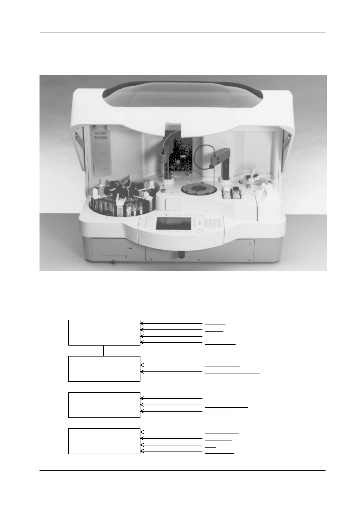
The sequence of operation of Elecsys 1010 is as follows:
Pick-up of sample and
reagents
Incubation
Pick-up of incubate and
addition of wash and buffer
solutions
Measurement of
luminescence, data
evaluation and output
S/R rotor
MFA s/r
S/R dilutor
Clot detection
Incubation rotor
Temperature (incubator)
Bottle temperature
MFA assy (sipper)
Sipper dilutor
Measuring cell
Potentiostat
PMT
Temperature
FINAL 2.1 - February 2000
Chapter 1Page 1
Page 10

Elecsys 1010 Service Manual
IntroductionIntroduction
Introduction
IntroductionIntroduction
When the instrument cover top is closed, loading of two
This System Description explains functions and their
interrelationship.
Short Description of the InstrumentShort Description of the Instrument
Short Description of the Instrument
Short Description of the InstrumentShort Description of the Instrument
The Elecsys 1010 is a Multi-Batch-Analyzer which analyzes
immunological tests according to the principle of electrochemical luminescence (ECL). This measuring system is
also called ORIGEN® technology. The emitted photons are
measured with a photomultiplier (photon counts).
STAT (short-turn-around-time) samples is possible outside
of the direct range of action of the MFA arms and rotors. Pull
out the control panel like a drawer, behind which the holder
for the above mentioned STAT samples is located. By
pushing the control panel back in, the STAT samples are
within the direct range of the pipette needle under the closed
instrument cover without mechanically or logically
interrupting an ongoing process.
Elecsys 1010 has two driving blocks for the sample/
reagent rotor and the incubation rotor.
Elecsys 1010 has all the modules and components
necessary for executing the entire analysis including the
measurements and evaluation. When operating the
instrument (e.g. for test selection and sample placement),
the user is guided by menus on the keyboard. Softkeys and
function keys can be used for interacting with the
instrument. Samples (both in primary tubes and in secondary
cups), reagents and calibrators are to be positioned on the
sample/ reagent (s/r) rotor. A special reagent bottle
combination (RackPack) contains the reagents needed for
a test. Each RackPack has a 2-dimensional bar code with
all data specific of the test. Positive user identification
(PSID) is possible with samples in primary tubes. With
samples in secondary cups, patients are identified manually
by using the keyboard. After reading the bar code, the RUN
is started and performed automatically.
CalibrationCalibration
Calibration
CalibrationCalibration
At the beginning of a RUN a calibration can be performed.
The system imposes a full calibration
- if a new reagent (with a new batch number) is put in.
- at regular time intervals (specific of the reagent)
This is done by calibrators specific of the test (normally 2
levels).
Quality ControlQuality Control
Quality Control
Quality ControlQuality Control
The instrument software contains all programs necessary
for the quality control. Data input, management and security
is done by using the keyboard.
Instrument AssemblyInstrument Assembly
Instrument Assembly
Instrument AssemblyInstrument Assembly
ELECSYS 1010 is a desk top model and is suitable for a
standard laboratory bench. The instrument can be loaded
from the front. The instrument cover top must be closed
during the RUN.
The sample/reagent rotor is divided into 6 segments. The
two outer trays can hold samples in so-called primary tubes
of various diameters and heights. Control and calibrator
liquids are normally also positioned in these trays. A
maximum of 6 RackPacks with 2 reagents and one bead
container each are arranged radially between the sample
segments. The two inner trays are provided for secondary
cups. The labels on the primary tubes on the two outer trays
and the RackPacks can be read by a bar-code reader
(BCR).
The rotor assy is equipped with toothed disks and LEDs for
controlling and checking the rotor functions. The sample/
reagent rotor is removable.
The incubation rotor is an aluminum block heated to 37°C.
It can hold 4 identical segments with 32 incubation vessels
each. These incubation vessels are small conical plastic
tubes that hold the incubation material. When preparing the
RUN, the user loads the incubation rotor with the 4 segments.
The incubation rotor is not removable.
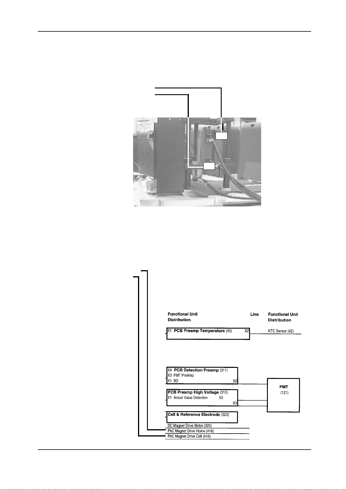
Detection ModuleDetection Module
Detection Module
Detection ModuleDetection Module
The ECL measuring cell is located in the detection module.
The photomultiplier (PMT), which is shielded from
electromagnetic radiation by a special housing, as well as
the holder for the pre-amplifier and the high-voltage module
are located above the measuring cell. The magnet with the
drive for the bead capturing is under the measuring cell. The
magnet is moved vertically from below to the bottom of the
measuring cell by a motor/spindle unit. This internal
assembly is incorporated in a housing, which serves as an
optical, electrical and thermal shield. The optimum
temperature for the process of ORIGEN
®
technology is
28°C. Therefore, the temperature of the entire detection
module is set at 28°C.
MFA AssysMFA Assys
MFA Assys
MFA AssysMFA Assys
The instrument is designed to be serviced exclusively from
the front, i.e. all components can be taken out and exchanged
from the front.
The functional elements (dilutors, rotors, wash stations,
bottle temperature assys) have covers that can be easily
removed for service. The keyboard is located outside of
the closed instrument cover top.
FINAL 2.1 - February 2000
The MFA assys transport the
a) sample/reagent from the sample/reagent rotor to
the incubation vessels and
b) incubation material as well as ProCell and CleanCell
to the measuring cell.
The ProCell is a liquid required for generating the ECL
signal. CleanCell is an auxiliary liquid used for cleaning the
measuring cell and preparing it for the next measurement.
Page 2
Chapter 1
Page 11

Elecsys 1010 Service Manual
All components involved in the sample/reagent processes
are cleaned with system water.
Arms are mounted on the MFAs. The sample arm holds the
sample needle and the bead mixer. The sipper arm holds
the sipper needle. The LLD electronic system and the
contact sensory system (crash detection) are also located
in the arms. The assembly of both MFAs is identical except
for the arm adapters.
The contact sensory system consists of mechanical and
electronic hardware components. It records the contact of
the needle and the bead mixer with a solid surface, e.g. the
bottom of the container or a closed RackPack.
Rotation and lifting are controlled by toothed disks / vanes
and photo couplers. Horizontal and vertical movements are
normally performed in succession.
Bottle TemperatureBottle Temperature
Bottle Temperature
Bottle TemperatureBottle Temperature
Elecsys 1010 has 2 bottle temperature systems, one for
ProCell bottle and one for CleanCell bottle. Bottles are
refrigerated to approx. 8°C and will reach the desired
temperature of 28°C after approx. 1hr. The actual
temperature is controlled by NTC resistors in the housing
walls.
by two membrane pumps.
Another membrane pump is located on the back of the
s/r dilutor. This pump has the following functions:
1. Fill the s/r system with system water.
2. Rinse s/r tubing and needle after pipetting.
ValvesValves
Valves
ValvesValves
The flow of system water to the wash stations for bead
mixer, s/r needle and sipper needle is controlled by four
valves (2-way).
The water discharge from the wash stations is controlled by
four valves (3-way).
Various liquid levels in the wash stations are possible by
setting the 3-way valves at different positions.
Another valve controls the flow of the measuring material
to the measuring cell.
Wash StationsWash Stations
Wash Stations
Wash StationsWash Stations
Elecsys 1010 has four wash stations. There are two wash
stations for the s/r needle and one wash station each for the
sipper needle and the bead mixer. The wash stations use
system water.
LLDLLD
LLD
LLDLLD
DilutorsDilutors
Dilutors
DilutorsDilutors
Elecsys 1010 has 2 dilutors. These are glass cylinders in
which pistons are precisely moved at a defined number of
increments. When going down, liquids are aspirated. When
going up, an exact amount of liquid is discharged by
displacement. The direction of the liquid flow can be
controlled by reversing valves at the entrance of the dilutors.
The dilutors are moved by stepping motors.
The two dilutors have different functions:
The needle of the s/r dilutor aspirates the sample, reagents
and microparticles in a defined sequence. The media are
separated from the system liquid (H
The aspirated material is discharged into the incubation
O) by an air bubble.
2
vessels through the sample needle. After the sample/
reagent process, the needle is internally cleaned with
system water by means of the rinsing pump.
The sipper dilutor is located behind the measuring cell and
pulls the incubate, ProCell and CleanCell in a defined
sequence through the measuring cell. Then the
measurement is performed. After that the needle is internally
rinsed with CleanCell. The needle is externally cleaned with
system water.
PumpsPumps
Pumps
PumpsPumps
The s/r and the sipper needle have one liquid level detection
unit (LLD) each. The s/r-LLD detects samples, reagents,
incubate and wash water. The sipper LLD detects incubate,
ProCell, CleanCell and wash water.
Clot DetectionClot Detection
Clot Detection
Clot DetectionClot Detection
On the sample/reagent side, there is a risk of (blood) clot
formation in the samples. This can be caused by pollution
and/or belated clotting of the samples. Changes in the
vacuum profile when picking up the samples are identified
as clots by means of a differential pressure converter. The
appropriate cleaning steps will be taken.
PMTPMT
PMT
PMTPMT
The photomultiplier tube (PMT) receives and amplifies the
luminescence signal and converts it to an equivalent voltage.
The PMT window is located at a defined distance vertically
above the cell work electrode. High-voltage power supply
is required for amplification.
High-VoltageHigh-Voltage
High-Voltage
High-VoltageHigh-Voltage
High-voltage is used for amplifying the luminescence signal
generated in the measuring cell. The control range spans
from 500 V to1100 V.
The instrument has 4 built-in pumps. The waste pump, a
peristaltic pump, pumps the measuring material and system
liquids into the waste container. The wash stations are fed
FINAL 2.1 - February 2000
PotentiostatPotentiostat
Potentiostat
PotentiostatPotentiostat
The potentiostat controls the electrochemical redox process
in the cell.
Chapter 1Page 3
Page 12

Elecsys 1010 Service Manual
Measuring CellMeasuring Cell
Measuring Cell
Measuring CellMeasuring Cell
Power Supply AssyPower Supply Assy
Power Supply Assy
Power Supply AssyPower Supply Assy
The cell has three electrodes: the work electrode (on which
the microparticles are deposited), the counter electrode
and the reference electrode. For the measurement, a
constant voltage is applied between work electrode and
counter electrode.
It is equipped with an input for input voltages of approx. 80
- 260 volts and 50-60 Hz. The fuses are not accessible to
the customer and can only be exchanged by service
personnel.
Rotor / Dilutor / MFA DrivesRotor / Dilutor / MFA Drives
Rotor / Dilutor / MFA Drives
Rotor / Dilutor / MFA DrivesRotor / Dilutor / MFA Drives
The rotors, dilutor pistons and the MFAs are moved by
stepping motors. In order to avoid the loss of steps, the
motions are controlled by photo couplers and toothed
disks. Moreover, forward/backward motions can be
recognized by two photo couplers placed at an angle of 90°.
TemperaturesTemperatures
Temperatures
TemperaturesTemperatures
Elecsys 1010 has 4 systems for setting the temperatures
of liquids.
The luminescence liquid is measured at a temperature of
28°C. The temperatures of the incubate picked up by the
incubator and the liquids used for the measurements
(CleanCell and ProCell) are preset inside the detection
module. The immunological reaction occurs at 37°C
(incubator temperature).
PCPC
PC
PCPC
The PC is a standard PC assembly (CPU 486 DX 2,
66MHz, 8MB RAM) with Roche-owned functions. An 1.44
MB floppy disk drive serves as drive a. The system can be
started and reloaded from disk drive a:. A flash-E
2
PROM
serves as a hard disk replacement. The general program
and changeable parameters are filed here. The LC display
is controlled by the VGA controller.
Barcode Reader / BCRBarcode Reader / BCR
Barcode Reader / BCR
Barcode Reader / BCRBarcode Reader / BCR
A bar-code reader (BCR) is attached to the sample/reagent
rotor. It reads and decodes primary sample tubes (on the
1st and 2nd tray on the rotor) and reagent RackPacks
whenever the rotor passes the reader and transfers the
data to the PC by a built-in RS 232 interface. The reader
decodes 2-dimensional (PDF 417) and all standard bar
codes.
Software Distribution /ProcessorsSoftware Distribution /Processors
Software Distribution /Processors
Software Distribution /ProcessorsSoftware Distribution /Processors
The entire Elecsys 1010 software is distributed over a total
of 8 processors. The master board has a 486 processor.
The measuring, sipper, temperature, rotor and s/r modules
have an 80196 processor. The incubation module and the
clot detection are controlled by an 8051derivative. The
keyboard assy and the printer have one CPU each.
Keyboard AssyKeyboard Assy
Keyboard Assy
Keyboard AssyKeyboard Assy
The keyboard assy consists of the keyboard, the keyboard
controller, an acoustic signal transmitter, the LC display
and some LEDs. The keys are short-stroke touch contact
keys. An additional keyboard can be connected to the
bottom side of the keyboard assy by using a 5-pin plug
(standard keyboard plug). One non-standard function is a
signal transmitter (piezo) that can be activated on several
frequencies. The display is a 640 x 480 dot LC display. In
order to prevent reflections when reading the display in the
keyboard assy drawer, it is possible to incline it.
PrinterPrinter
Printer
PrinterPrinter
Elecsys 1010 has a thermoprinter with a printing width of
640 pixels. This corresponds to the display resolution. An
immediate hard copy output is possible.
FINAL 2.1 - February 2000
Page 4
Chapter 1
Page 13

Elecsys 1010 Service Manual
1.1.21.1.2
1.1.2
1.1.21.1.2
Principles of the AnalysisPrinciples of the Analysis
Principles of the Analysis
Principles of the AnalysisPrinciples of the Analysis
See Chapter 5 of the Operator's Manual for
details of the test principles used on Elecsys
1010.
FINAL 2.1 - February 2000
Chapter 1Page 5
Page 14

Elecsys 1010 Service Manual
1.1.31.1.3
1.1.3
1.1.31.1.3
Run
This chapter describes processes going on in different
tests, e g. the placement of STAT samples during the run,
the automatic rerun and the system preparation after
start, as well as system evaluation at the end of a run.
Assay Protocols
There are 24 independent assay protocols used for
determining the pipetting scheme of tests. Further
protocols (no. 24 to no. 26) are used for checking the
instrument.
The assay protocols are stored in the system (max. 64)
and can only be modified and/or extended by a software
update.
In each test a minimum of four liquids, the sample itself,
reagent 1, reagent 2 and the microparticles, are processed.
The following abbreviations will be used for the liquids:
MP: Microparticles
B: Microparticles (test RackPack, assay RackPack)
R0: Diluent ("all-purpose diluent", special RackPack)
RM: Pretreatment solution for IgM or IgG tests
PS: Prereaction solution (pretreatment solution in
RI: Reagent 1 (assay RackPack )
R2: Reagent 2 (assay RackPack )
S: Undiluted sample/ calibrator/ check
DL: Diluted sample/ calibrator/ check
D: Aspiration into the measuring cell and optical
i: Incubation time
Pipetting SchemePipetting Scheme
Pipetting Scheme
Pipetting SchemePipetting Scheme
(in special RackPack)
special RackPack)
detection
5. Aspirate R2 --> discharge R2 into the third incubation
vessel.
6. Wait until incubation time i2 is over.
7. Measurement.
One step is taken after the other, allowing for the incubation
time. The last step is always the measurement.
The processing of these liquids is determined by the four basic
protocols 0 through 3. They define which liquids are processed
in which pipetting step. On the basis of the basic protocols, the
processing with pretreatment liquids (RO, RM or PS) is
defined in the protocols 4 through 23. Read the sequence of
pipetting steps within one protocol from left to right. The
example
shows the following sequence:
1. Aspirate R0 and sample S --> discharge both liquids
2. Aspirate R0 and the diluted sample DL from the first
3. Aspirate microparticles, R1 and the diluted sample
4. Wait until the incubation time i1 is over.
FINAL 2.1 - February 2000
Protocol 9 (dilution with 2 different assays)Protocol 9 (dilution with 2 different assays)
Protocol 9 (dilution with 2 different assays)
Protocol 9 (dilution with 2 different assays)Protocol 9 (dilution with 2 different assays)
into the first incubation container.
incubation vessel --> discharge both liquids into the
second incubation vessel.
DL from the second incubation vessel --> discharge
all three liquids into the third incubation vessel.
Page 6
Chapter 1
Page 15

Elecsys 1010 Service Manual
Assay ProtocolsAssay Protocols
Assay Protocols
Assay ProtocolsAssay Protocols
TableTable
Table
TableTable
No. Pipetting Step 0 Inc 0
Pipetting Step
1
Inc 1
Pipetting Step
2
Inc 2 Det.
0 B R1 R2 S i1 D X
1 B R1 S i1 R2 i2 D X
2 R1 R2 S i1 B i2 D X
3 R1 S i1 B R2 i2 D X
4 R0 S B R1 R2 DL i1 D
5 R0 S B R1 DL i1 R2 i2 D
6 R0 S R1 R2 DL i1 B i2 D
7 R0 S R1 DL i1 B R2 i2 D
8 R0-> DL1 R0 B R1 R2 DL i1 D
9 R0 S-> DL1 R0 B R1 DL i1 R2 i2 D
10 R0 S-> DL1 R0 R1 R2 DL i1 B i2 D
11 R0 S-> DL1 R0 R1 DL i1 B R2 i2 D
12 PS S i0 B R1 R2 i1 D
13 PS S i0 B R1 i1 R2 i2 D
14 PS S i0 R1 R2 i1 B i2 D
Main assay Remarks
15 PS S i0 R1 i1 B R2 i2 D
16 RM S i0 B R1 R2 DL i1 D
17 RM S i0 B R1 DL i1 R2 i2 D
18 RM S i0 R1 R2 DL i1 B i2 D
19 RM S i0 R1 DL i1 B R2 i2 D
20 RM S-> DL1 RM i0 B R1 R2 DL i1 D
21 RM S-> DL1 RM i0 B R1 DL i1 R2 i2 D
22 RM S-> DL1 RM i0 R1 R2 DL i1 B i2 D
23 RM S-> DL1 RM i0 R1 DL i1 B R2 i2 D
24 R1 R1 D X
25 R1 R2 D X
26 R2 R2 D X
27 R1 B i1 D X
28
29...
... Reserve
only needed
for instrument
checks,
not part of
the RUN
...63
E-Tab1: Assay Protocols
FINAL 2.1 - February 2000
Chapter 1Page 7
Page 16

Elecsys 1010 Service Manual
Pipetting StepsPipetting Steps
Pipetting Steps
Pipetting StepsPipetting Steps
The processing of the assay protocols is divided into four
pipetting steps: pipetting step 0, the so-called pretreatment
step, pipetting steps1 and 2, and the measuring step. The
pipetting steps are divided into partial steps (e.g. pipette R1).
The sequence of the partial steps is (regarding the liquid pickup by the s/r needle): R1, R2, B, S.
The pipetting steps / partial steps according to the assay
protocols are described below. The pick-up sequence
during pretreatment is always: reagent before sample (in
both steps).
For each pipetting step and/or measuring step, a generally
applicable step can be described. Figures 1 to 3 give an
overview of these pipetting steps.
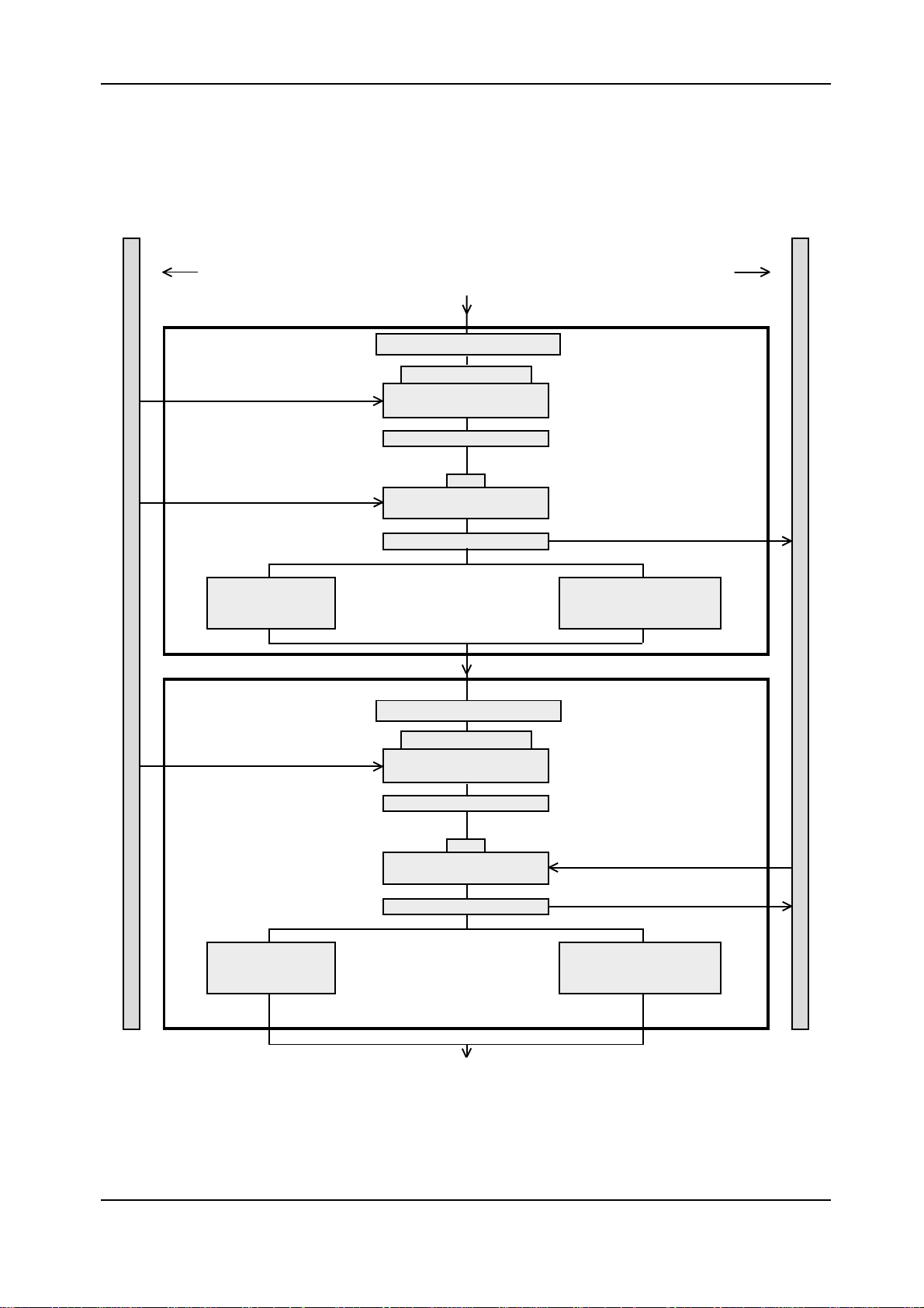
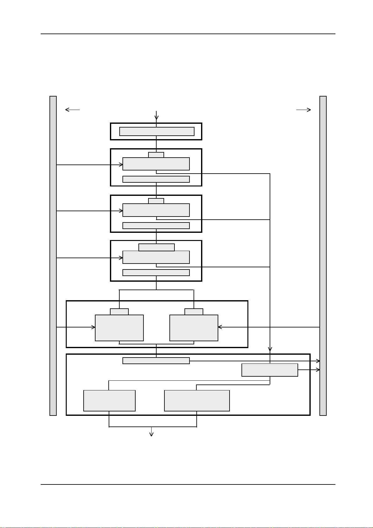
Pipetting Step 0Pipetting Step 0
Pipetting Step 0
Pipetting Step 0Pipetting Step 0
In pipetting step 0 the sample is pretreated. It has one or two
increments. In the figure, these increments are called "Block
1 and 2".
- Block 1 is passed through for protocols 4 through 23.
- Block 2 is passed through for protocols 8 through 11
and 20 through 23.
Each block consists of
- aspiration of the separation air bubble
- aspiration of the pretreatment liquid from the sample
rotor
- washing in wash station 1
- aspiration of the sample
- washing and rinsing in wash station 1 or
rinsing in wash station 2, rehomogenizing of the
microparticles and washing
Rinsing and washing in wash station 2 with simultaneous
rehomogenizing of the microparticles can only be
performed one time, always at the end of a pipetting step.
The difference between block 1 and block 2 is the
aspiration of the diluted sample from the incubation rotor.
- In block 1, the sample is aspirated from the sample
rotor, and the samples are discharged into the first
incubation vessel.
- In block 2, the sample is aspirated from the first
incubation vessel, and the liquids are discharged into
the second incubation vessel.
FINAL 2.1 - February 2000
Page 8
Chapter 1
Page 17
Elecsys 1010 Service Manual
Pipetting Step 0Pipetting Step 0
Pipetting Step 0
Pipetting Step 0Pipetting Step 0
Sample rotor Incubation rotor
Block 1Block 1
Block 1
Block 1Block 1
Aspirate
Aspirate
Block 2Block 2
Block 2
Block 2Block 2
Aspirate
Wash and rinse in
wash station 1
Aspirate separation air bubble
R0 or PS or RM
Aspirate sample by using
LLD
Wash in wash station 1
S
Aspirate sample by using
LLD
Discharge
Aspirate separation air bubble
R0 or RM
Aspirate pretreatment
liquid by using LLD
Discharge
Wash and rinse in
wash station 2 and
rehomogenize microparticles
Wash and rinse
in wash station 1
Figure 1: Pipetting step 0
FINAL 2.1 - February 2000
Wash in wash station 1
DL
Aspirate pretreated sample
by using LLD
Discharge
Aspirate
Discharge
Wash and rinse in
wash station 2 and
rehomogenize microparticles
Chapter 1Page 9
Page 18

Elecsys 1010 Service Manual
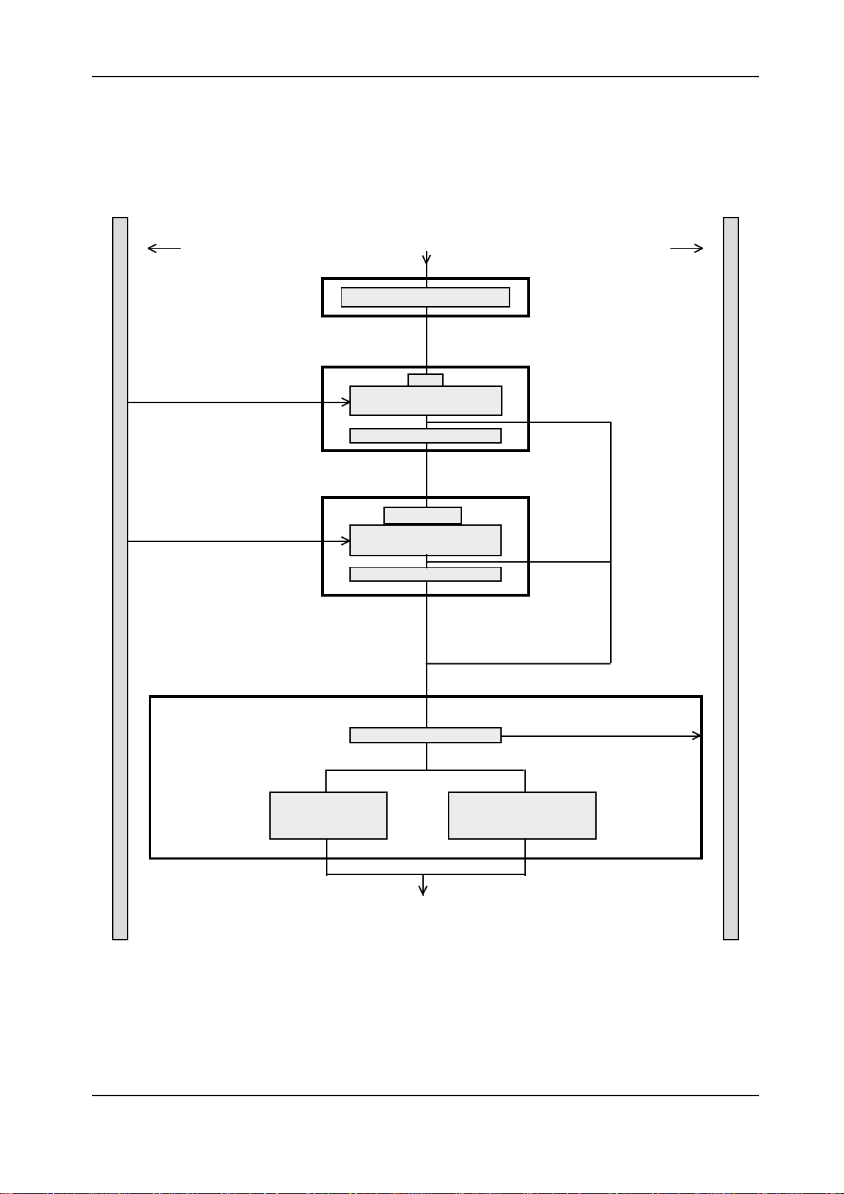
Pipetting Step 1Pipetting Step 1
Pipetting Step 1
Pipetting Step 1Pipetting Step 1
Pipetting step 1 is also divided into blocks and always
starts with block 1.
- Aspirate the separation air bubble.
In blocks 2, 3 and 4, reagents are aspirated. All three
blocks are passed through in the following sequence:
- Aspiration of R1, R2 or microparticles.
- Discharging of fluids after the last reagent has been
picked up and the sample pretreated with PS. The
sample pretreated with PS will be further processed in
block 6.
- Washing in wash station 1.
The assay protocols determine which and how many of the
blocks will be passed through in pipetting step 1.
In block 5, the sample is aspirated. The pretreated sample DL
is
- aspirated from the first incubation vessel and is
discharged into a second incubation vessel in block 6,
if it has been pretreated with R0 or RM in one
increment (see pipetting step 0).
- aspirated from the second incubation vessel and is
discharged into a third incubation vessel in block 6, if
it has been pretreated with R0 or RM in two increments
(see pipetting step 0).
If sample S has not been pretreated, it will be aspirated from
the sample rotor and discharged into the first incubation vessel
in block 6.
In block 6, the liquids are discharged into the incubation rotor,
and the s/r needle is washed and rinsed. If the sample has been
pretreated with PS, the aspirated liquids will be added to the
first incubation vessel (see pipetting step 0).
The rehomogenizing of the microparticles and the washing /rinsing in wash station 2 will be performed if in the
next cycle microparticles are pipetted in one pipetting
step 1.
FINAL 2.1 - February 2000
Page 10
Chapter 1
Page 19
Elecsys 1010 Service Manual
Pipetting Step 1Pipetting Step 1
Pipetting Step 1
Pipetting Step 1Pipetting Step 1
Sample rotor Incubation rotor
Block 1Block 1
Block 1
Aspirate
Aspirate
Block 1Block 1
Block 2Block 2
Block 2
Block 2Block 2
Block 3Block 3
Block 3
Block 3Block 3
Aspirate separation air bubble
R1
Aspirate reagent 1
by using LLD
Wash in wash station 1
R2
Aspirate reagent 2
by using LLD
Aspirate
Block 5Block 5
Block 5
Block 5Block 5
Aspirate
Block 6Block 6
Block 6
Block 6Block 6
Block 4Block 4
Block 4
Block 4Block 4
Aspirate sample by
using LLD (clot and
foam detection)
Wash and rinse
in wash station 1
Wash in wash station 1
Microparticles
Aspirate microparticles
by using LLD
Wash in wash station 1
Discharge
Wash and rinse in wash
station 2 and rehomogenize
DLS
Aspirate pretreated
sample by using LLD
microparticles
Aspirate
Discharge sample
pretreated with PS
Figure 2: Pipetting step 1
FINAL 2.1 - February 2000
Chapter 1Page 11
Page 20

Elecsys 1010 Service Manual
Pipetting Step 2Pipetting Step 2
Pipetting Step 2
Pipetting Step 2Pipetting Step 2
Pipetting step 2 is divided into 4 blocks. Like pipetting
step 1, it always starts with block 1:
- Aspirate the separation air bubble.
In blocks 2 and 3, reagents are aspirated. Both blocks are
passed through in the following sequence:
- Aspirate R2 or microparticles.
- Discharge liquid into the incubation rotor after the last
reagent has been picked up.
- Wash in wash station 1.
The assay protocols determine which and how many of the
blocks will be passed through in pipetting step 2.
In block 4, the liquids are discharged into the incubation rotor,
and the s/r needle is washed and rinsed. The liquids will be
- added to the first incubation vessel, if the sample has
not been pretreated or pretreated with PS.
- added to the second incubation vessel, if the sample
has been pretreated with R0 or RM in one increment.
- added to the third incubation vessel, if the sample
has been pretreated with R0 or RM in two increments.
The rehomogenizing of the microparticles and the washing /rinsing in wash station 2 will be performed if in the
next cycle microparticles are pipetted in one pipetting
step 1.
FINAL 2.1 - February 2000
Page 12
Chapter 1
Page 21
Elecsys 1010 Service Manual
Pipetting Step 2Pipetting Step 2
Pipetting Step 2
Pipetting Step 2Pipetting Step 2
Sample rotor Incubation rotor
Block 1Block 1
Block 1
Aspirate
Block 1Block 1
Block 2Block 2
Block 2
Block 2Block 2
Aspirate separation air bubble
R2
Aspirate reagent 2
by using LLD
Wash in wash station 1
Aspirate
Block 4Block 4
Block 4
Block 4Block 4
Block 3Block 3
Block 3
Block 3Block 3
Wash and rinsei n
wash station 1
Microparticles
Aspirate microparticles by
using LLD
Wash in wash station 1
Discharge
wachen und spülen in
Wash and rinse in
wash station 2 and
rehomogenize microparticles
Figure 3: Pipetting step 2
FINAL 2.1 - February 2000
Chapter 1Page 13
Page 22

Elecsys 1010 Service Manual
Measuring StepMeasuring Step
Measuring Step
Measuring StepMeasuring Step
Measuring step actions take place around the measuring
cell, e.g. in the incubator, sipper needle, measuring cell
or in the sipper system dilutor. The measuring step has
the following increments:
- Pick-up of the incubate ( - sampling, pick -up ) (preconditioning with ProCell included).
- Transport of the incubate with ProCell (preconditioning with ProCell included).
- Capturing with ProCell
- Washing with ProCell
- Measuring -> optical measurement
- Pick-up of CleanCell solution for cleaning 1
- Pick-up of air and CleanCell alternately
- Solution for cleaning 2
- Pick-up of ProCell for cleaning 3
- Pick-up of ProCell for post -conditioning
FINAL 2.1 - February 2000
Page 14
Chapter 1
Page 23
Elecsys 1010 Service Manual
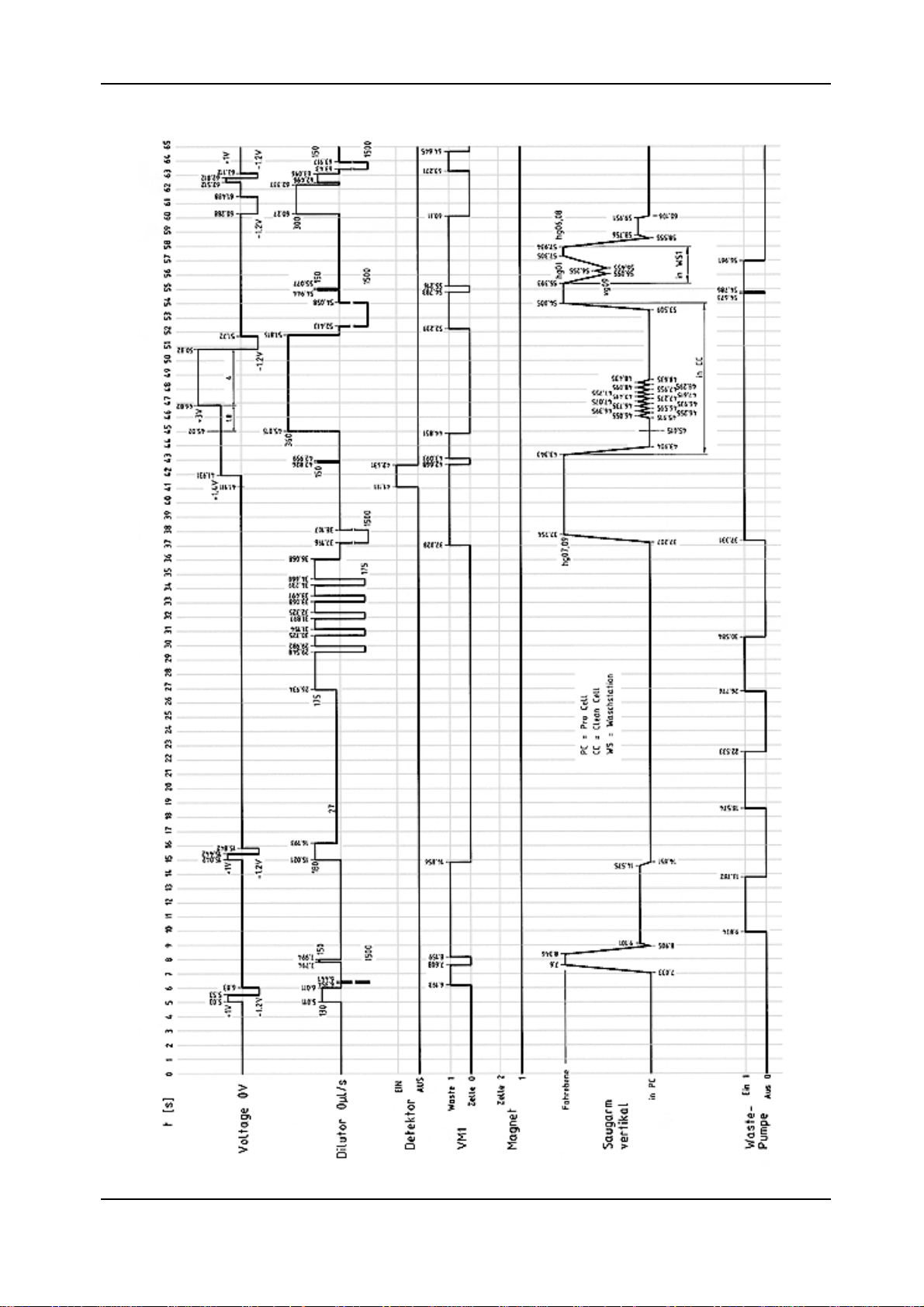
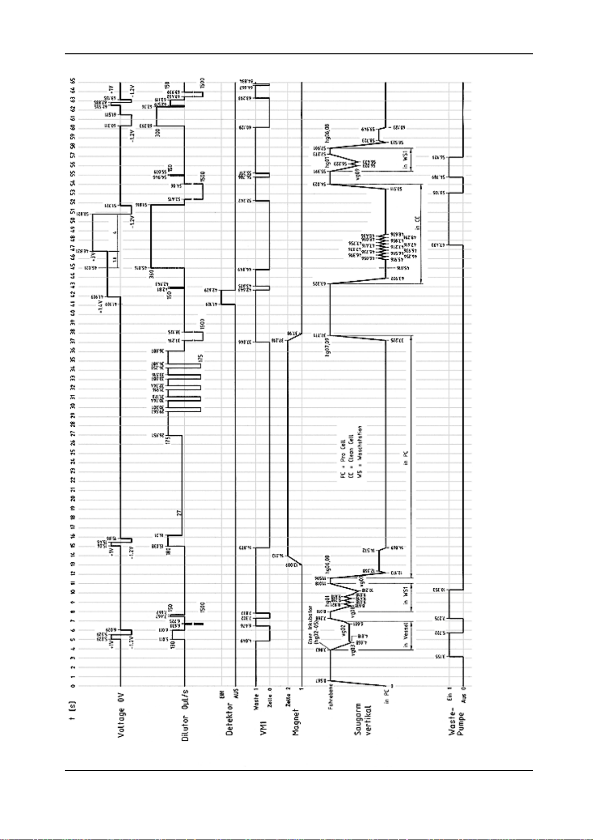
1.1.3.11.1.3.1
1.1.3.1
1.1.3.11.1.3.1
Timing DiagramTiming Diagram
Timing Diagram
Timing DiagramTiming Diagram
FINAL 2.1 - February 2000
diag1.tif
Chapter 1Page 15
Page 24
Elecsys 1010 Service Manual
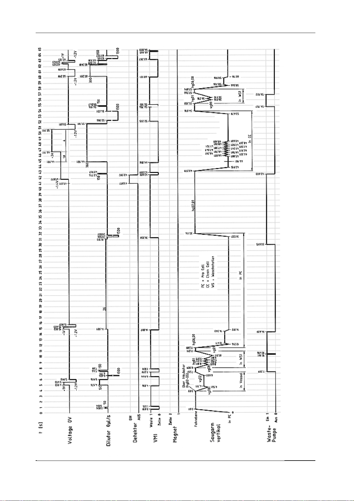
FINAL 2.1 - February 2000
Page 16
diag2.tif
Chapter 1
Page 25
Elecsys 1010 Service Manual
FINAL 2.1 - February 2000
diag3.tif
Chapter 1Page 17
Page 26

Elecsys 1010 Service Manual
1.21.2
1.2
1.21.2
Analyzer dimensions Height: 620 (mm)
Electrical Supply voltage 100 - 240 (V) AC at 50/60 (Hz)
Environmental conditions Temperature 18 (°C) to 32 (°C)
System SpecificationSystem Specification
System Specification
System SpecificationSystem Specification
Depth: 780 (mm)
Width: 960 (mm)
Weight approx. 110 (kg)
Power consumption max 0.61 (kVA)
Fuse circuit 16 (A) time-lag at 230 (V) AC
Heat generation
Ambient temperature note change during
one batch run
approx. 2000 (kJ/h) resp. 481 (kcal/h)
resp. 1912 (BTU/h)
max. ± 3 (°C)
rel. humidity 20 (%) to 85 (%) without condensation
Noise level according to DIN
43635
Water supply Water tank approx. 4,2 (l)
Waste water connection
Throughput ECL measurements approx. 50 (tests/h)
Samples Sample volume per test 10 (µl) to 50 (µl)
Continuous operation max. 60 (dBA)
Peak level max. 65 (dBA)
Water quality (conductivity) sub-micron filtered <10 µS/cm
Water consumption approx. 3 (l) for 128 test
Waste container for measuring material,
system water, ProCell, CleanCell
Sample detection
Sample rotor for routine samples,
calibrators and controls
Usable sample bar codes
approx. 5 (l)
by Liquid Level Sensor and Clot
Detector of the sample / reagent needle
42 positions for primary tubes, 18
positions for secondary cups
2 positions for STAT samples
NW7 (Codabar), Code 39, Code 128,
Interleave 2 of 5
Reagent Reagent capacity 6 reagent channels
by Liquid Level Sensor of the sample/
reagent needle
E-Tab2
FINAL 2.1 - February 2000
Reagent detection
Page 18
Chapter 1
Page 27

Elecsys 1010 Service Manual
Bottle volume for CleanCell and ProCell 380 (ml)
Reagent ID by 2-dim. bar code (PDF 417)
Incubator Incubator capacity 128 plastic assay cups (4 x 32)
Volume of assay cups 200 (µl)
ambient temperature 18°C to 20°C
Incubation temperature
Incubation time 9 / 18 (min)
37°C + 0.3°C - 0.8°C
ambient temperature 20°C to 32°C
37°C + 0.3°C - 0.3°C
Measuring system Measuring method
Calibration method 2 point calibration
PC Disk drive Floppy disk 3,5" / 1.44 MB
Interfaces
LCD
Thermoprinter Paper width 110 (mm)
E-Tab3
Integral measurement of luminescence
signal
1 Centronics for printer, 1 RS 232 for
laboratory EDP
Black-and-white VGA LCD with 640 x
480 pixels
FINAL 2.1 - February 2000
Chapter 1Page 19
Page 28

Elecsys 1010 Service Manual
1.3.3 Precautions and Hazards1.3.3 Precautions and Hazards
1.3.3 Precautions and Hazards
1.31.3
1.3
1.31.3
The data and information provided in this manual correspond
to the state of knowledge existing at the time of introducing
the Elecsys 1010 onto the market. Any important changes
will be taken into account in the next edition of this manual.
The respective packaging leaflet should be regarded as
authoritative.
Operator Precautions andOperator Precautions and
Operator Precautions and
Operator Precautions andOperator Precautions and HazardsHazards
Hazards
HazardsHazards
1.3.3 Precautions and Hazards1.3.3 Precautions and Hazards
All electrical equipment is potentially hazardous. Never
remove covers without first ensuring that it is isolated from
the AC supply, unless specific maintenance instructions or
repairs are being carried out by authorized Roche
Diagnostics personnel.
The hard- and software is subject to a program of continuous
evaluation and improvement and, therefore, may be changed
in the future. This also concerns service requirements.
This service manual was created for the telephone and
technical service staff.
1.3.1 Contact Persons1.3.1 Contact Persons
1.3.1 Contact Persons
1.3.1 Contact Persons1.3.1 Contact Persons
Technical Product Management and Support
Department: LI-TT
Phone: 0621 / 759 / 3227
8802
Fax No: 0621/ 759 / 4591
Logistics Hotline (RA):
Phone: 0621 / 759 / 4389
Fax No.: 0621 / 759 / 4613
8093
When calling from abroad, drop the "0" and add the country
code (+ 49).
1.3.2 Proved Security1.3.2 Proved Security
1.3.2 Proved Security
1.3.2 Proved Security1.3.2 Proved Security
All samples and reagents should be treated with caution
accorded to those known to contain pathogenic organisms.
Similarly, the cleaning of component part of Elecsys 1010
should be done with respect to human health.
Warning:Warning:
Warning:
Warning:Warning:
All components used on Elecsys 1010 must be regarded
as potentially dangerously contaminated when doing repair
work. Use rubber gloves or double gloves whenever cleaning
or sterilizing components. the most frequently used
components (tubings, cuvette, measuring chamber flap,
sip. lever and waste container) should be cleaned and
treated with a suitable disinfecting solution (75% alcohol)
prior to doing any service work.
Disinfect and wash hands after work is completed.
This instrument has been constructed and checked in
accordance with Standards IEC 1010. When the instrument
leaves our factory it is in perfect order from the point of view
of work safety. To keep it that way and to ensure safe
operation the user must follow the instructions and warnings
given in the operation instruction manual.
The electrical protection of the apparatus to Class I (it has
a protective earth).
This instrument has been constructed according to the
regulations of DIN IEC 601, part: "Security of Electromedical
Instruments: General Guidelines" and left our factory in
perfect condition regarding work safety.
The instrument obtained the GS mark for proved security
from the TÜV.
In order to ensure safe operation the user must follow the
instructions and warnings given in the instruction manual.
This instruments meets protection 1 (earth conductor wire).
FINAL 2.1 - February 2000
The power plug must only be inserted into a socket that has
a protective contact. The protection must not be abolished
by using an extension lead that does not have a protective
earth wire.
Warning:Warning:
Warning:
Warning:Warning:
Any break in the earth wire inside or outside the apparatus
and any loose connection of the earth wire can make the
operation of the apparatus dangerous. A deliberate break
or interruption is not allowed.
When the housing is opened or components are being
removed (except when this can be done by hand), live parts
may be exposed. Connection may also be live.
Therefore, if the carrying out of an adjustment, service or
repair on the open apparatus in the live state is unavoidable,
this must be done by an expert who is familiar with the
dangers involved.
Page 20
Chapter 1
Page 29

Elecsys 1010 Service Manual
Make sure you only use fuses of the specified type and
rated amperage when replacing. Repaired fuses must not
be used and the fuse holder must not be bypassed.
If you have any reason to believe that the instrument can no
longer operate safely, take it out of use and make sure no
one can use it accidentally.
It must be assumed that safe operation is no longer possible
when the instrument:
- shows visible signs of damage
- fails to operate
- has been stored under unfavourable conditions for
a fairly long time
- has been transported under rough conditions
The Elecsys 1010 should be used by appropriately qualified
persons only.
Warning:Warning:
Warning:
Warning:Warning:
In order to avoid electrostatic charging when working on the
electronics, use a grounding strap and a grounding mat.
For more information, please refer to operator manual.
FINAL 2.1 - February 2000
Chapter 1Page 21
Page 30

Elecsys 1010 Service Manual
1.4 Service Concept1.4 Service Concept
1.4 Service Concept
1.4 Service Concept1.4 Service Concept
1.4.11.4.1
1.4.1
1.4.11.4.1
From the early stage of development, Elecsys 1010 was
designed for simple error detection and easy exchangeability
of modules. This gives the service workshops the possibility
of a fast and easy repair of the instrument on service level
A (module level). No big stock or expensive equipment is
necessary and service technicians are easier to train.
Also, a permanent technical improvement in layout and
components took and takes place for better productivity
and economic production.
On repairable modules the quality and function is always
provided by the manufacturer according to the latest
technology. This keeps Elecsys 1010 always on the highest
quality level.
The exchange price for modules will be kept on a low level
to guarantee repairs, on an economical basis.
1.4.21.4.2
1.4.2
1.4.21.4.2
Service LevelService Level
Service Level
Service LevelService Level
RA-Procedure (Replacement ofRA-Procedure (Replacement of
RA-Procedure (Replacement of
RA-Procedure (Replacement ofRA-Procedure (Replacement of
defective parts)defective parts)
defective parts)
defective parts)defective parts)
- All defective parts ( non-"R" and "A" parts ) should be
kept on stock for a period of 7 months. In case the
manufacturer needs the part for investigation it will be
requested from Mannheim.
- All parts returned to Mannheim and not requested by
Mannheim will be send back at the expense of the
countries.
- The RA claim for warranty has to be in Mannheim no
later than 8 weeks after the problem date.
Exclusion of warrantyExclusion of warranty
Exclusion of warranty
Exclusion of warrantyExclusion of warranty
The aforementioned warranties do not apply in case of
improper use, handling, transportation or storage, faulty
installation, repair or maintenance, chemical influence or
contamination as well as damages resulting from that,
failure to follow operating instructions, alterations or
modifications of instruments or parts thereof not authorized
or recommended by RD GmbH and resulting damages,
normal wear and tear and in case of other circumstances
beyond the control of RD GmbH.
Handling of repairsHandling of repairs
Handling of repairs
Handling of repairsHandling of repairs
As a general rule, all instrument repairs should be carried
out by authorized and trained personnel only.
Warranty period for instruments and spare partsWarranty period for instruments and spare parts
Warranty period for instruments and spare parts
Warranty period for instruments and spare partsWarranty period for instruments and spare parts
The warranty period for instruments is 16 months starting
with the date of shipment ex works Mannheim/Federal
Republic of Germany or 12 months starting with the date of
the first installation, whichever period is shorter.
The warranty period for spare parts is 6 months from
installation date of the part, however not longer than 24
months after having delivered ex works Mannheim/Federal
Republic of Germany. Note: In case the instrument has a
remaining warranty period of more than 6 months, the parts
remain under warranty until the warranty period of the
instrument expires.
Handling of warranty claimsHandling of warranty claims
Handling of warranty claims
Handling of warranty claimsHandling of warranty claims
The warranty claim has to be handled via Return
Authorization procedure or accepted equivalent. Please
answer all the questions on the RA form with the greatest
care.Especially a detailed fault description is needed or the
warranty claim will not be accepted by the manufacturer.
Complete instruments are not accepted unless this has
been agreed with the service department of the relevant
product group responsible at RD GmbH.
Repair of parts marked with "R"Repair of parts marked with "R"
Repair of parts marked with "R"
Repair of parts marked with "R"Repair of parts marked with "R"
Parts which are economically worth repairing are marked
with "R" in the spare parts price list. New and repaired parts
could be recognized by different material numbers (language
version).
(e.g. new part: 1234567-001, repaired part: 1234567-984)
Repaired parts should be ordered together with new parts
via the order processing department in Mannheim (OUVDG). Parallel to the ordering process of a repaired part,
the defective part should be returned together with the filled
RA form (giving full details of the defect and marked choice
box with repair) to Logistic Instruments (Goods Receipt) in
MA-Wohlgelegen (LI-GS). Repair of instrumentsComplete
instruments are not accepted for replacement or repair
unless this has been agreed with the product group
responsible at RD GmbH. Before replacement or repair
can take place, the validity of the request must be examined
and the question of costs must be settled in a written
agreement with RD GmbH.
Terms of deliveryTerms of delivery
Terms of delivery
Terms of deliveryTerms of delivery
Important informationImportant information
Important information
Important informationImportant information
- Only parts marked with "A" in the price list are generally
accepted under warranty.
- Only return those parts marked with "R" in the spare
parts price list.
- Warranty claim for „R“ parts will be accepted, if the
part was returned to Mannheim.
FINAL 2.1 - February 2000
Shipments to the countries with the routine truck are c.i.f./
shipments outside this procedure are ex works Mannheim.
Emergency shipments require additional costs to be
charged.
Page 22
Chapter 1
Page 31

Elecsys 1010 Service Manual
Handling of costsHandling of costs
Handling of costs
Handling of costsHandling of costs
„Repaired“-parts (Material-No. 1234567-984) are shipped
at a repair price. In case the defective parts are not returned
within 3 or 8 weeks for european or oversea countries after
ordering the repaired part, the countries will be charged
later on with the difference to the new price.After the receipt
of a warranty request for „A“-parts, RDG will credit 100 %
of the currently effective ex MA price.In case the
manufacturer does not accept the warranty request, the
countries will be charged lateron with the R-price for Rparts and the new price for non R-parts.
RA formRA form
RA form
RA formRA form
Return Authorization. Please answer all the questions on
the RA form with the greatest care and sign the form.
- Country code
- Problem date
- Type of instrument
- Serial no. of the instrument
- Installation date of instrument
- Defective instrument or spare part
- Part number and material number of the spare part
- Old / new serial no.
- Fault description
- Alarm code
- Service / workshop report no.
In case of instrument out of warrantyIn case of instrument out of warranty
In case of instrument out of warranty
In case of instrument out of warrantyIn case of instrument out of warranty
- Installation date of spare part.
All returned parts should be individually labeled with the
corresponding RA No. and shipped together with the
completed RA form to:
Roche Diagnostics GmbH
Logistic Instruments
RA Management
Friedrich Ebert Str. 100
D - 68167 Mannheim
Germany
FINAL 2.1 - February 2000
Chapter 1Page 23
Page 32

Elecsys 1010 Service Manual
R
RA Form:RA Form:
RA Form:
RA Form:RA Form:
A copy of the RA Form is shown below.
Roche Diagnostics
Friedrich-Ebert-Strasse 100 Telefon : +49 (621) 759 81 84
D-68167 Mannheim Fax : +49 (621) 759 80 93
Germany
Return Authorization
No.:
Country code:
Date:
Instrument:
Serial No.:
Installation date:
Spare Part:
Customer: Address:
(will be filled in by BM)
Part No.: Qty.: Part Name: Repair Comments
Mat.-No.: Warranty
Installation date of Spare Part: Warranty Repair
OLD serial No.: Modification
NEW serial No.: Replacement
Fault Description:
Alarm Code:
Service Report No.: Workshop Report No.:
Place: Date: Signature:
Remarks
D
(will be filled in byRD)
NOS Credit FC
Fig.: RA.eps
FINAL 2.1 - February 2000
Page 24
Chapter 1
Page 33

Elecsys 1010 Service Manual
1010
10
1010
MaintenanceMaintenance
Maintenance
MaintenanceMaintenance
10.110.1
10.1
10.110.1
10.210.2
10.2
10.210.2
10.310.3
10.3
10.310.3
10.410.4
10.4
10.410.4
IntroductionIntroduction
Introduction
IntroductionIntroduction
10.1.110.1.1
10.1.1
10.1.110.1.1
Maintenance ScheduleMaintenance Schedule
Maintenance Schedule
Maintenance ScheduleMaintenance Schedule
Bi-weekly Analyzer MaintenanceBi-weekly Analyzer Maintenance
Bi-weekly Analyzer Maintenance
Bi-weekly Analyzer MaintenanceBi-weekly Analyzer Maintenance
10.3.110.3.1
10.3.1
10.3.110.3.1
10.3.210.3.2
10.3.2
10.3.210.3.2
10.3.310.3.3
10.3.3
10.3.310.3.3
10.3.410.3.4
10.3.4
10.3.410.3.4
10.3.510.3.5
10.3.5
10.3.510.3.5
Maintenance, As RequiredMaintenance, As Required
Maintenance, As Required
Maintenance, As RequiredMaintenance, As Required
10.4.110.4.1
10.4.1
10.4.110.4.1
10.4.210.4.2
10.4.2
10.4.210.4.2
10.4.310.4.3
10.4.3
10.4.310.4.3
Cleaning MaterialsCleaning Materials
Cleaning Materials
Cleaning MaterialsCleaning Materials
Perform SYSTEM CLEANING INTENSIVEPerform SYSTEM CLEANING INTENSIVE
Perform SYSTEM CLEANING INTENSIVE
Perform SYSTEM CLEANING INTENSIVEPerform SYSTEM CLEANING INTENSIVE
Clean the Microparticle MixerClean the Microparticle Mixer
Clean the Microparticle Mixer
Clean the Microparticle MixerClean the Microparticle Mixer
Clean the Sipper ProbeClean the Sipper Probe
Clean the Sipper Probe
Clean the Sipper ProbeClean the Sipper Probe
Clean the S/R ProbeClean the S/R Probe
Clean the S/R Probe
Clean the S/R ProbeClean the S/R Probe
Perform CELL CLEANING NORMALPerform CELL CLEANING NORMAL
Perform CELL CLEANING NORMAL
Perform CELL CLEANING NORMALPerform CELL CLEANING NORMAL
Clean the Analyzer Surfaces and CoverClean the Analyzer Surfaces and Cover
Clean the Analyzer Surfaces and Cover
Clean the Analyzer Surfaces and CoverClean the Analyzer Surfaces and Cover
Replacing Printer PaperReplacing Printer Paper
Replacing Printer Paper
Replacing Printer PaperReplacing Printer Paper
Clean the Rinse StationsClean the Rinse Stations
Clean the Rinse Stations
Clean the Rinse StationsClean the Rinse Stations
__________________________________________________________________________________________
_____________________________________________
__________________________________________________________________________________________
__________________________________________________________________________________________
_____________________________________________
__________________________________________________________________________________________
________________________________________________________________________
____________________________________
________________________________________________________________________
______________________________________________________
___________________________
______________________________________________________
__________________________________________________
_________________________
__________________________________________________
________________________________________________________________________
____________________________________
________________________________________________________________________
__________________________________________________________________________________
_________________________________________
__________________________________________________________________________________
________________________________________________________________________________________
____________________________________________
________________________________________________________________________________________
____________________________________________________________
______________________________
____________________________________________________________
________________________________________________________________
________________________________
________________________________________________________________
____________________________________________________
__________________________
____________________________________________________
________________________________________________________________________________
________________________________________
________________________________________________________________________________
______________________________________________________________________________
_______________________________________
______________________________________________________________________________
1010
10
1010
1010
10
1010
1010
10
1010
1010
10
1010
11
1
11
11
1
11
33
3
33
55
5
55
55
5
55
66
6
66
66
6
66
77
7
77
88
8
88
10.510.5
10.5
10.510.5
10.6 Preventive Maintenance10.6 Preventive Maintenance
10.6 Preventive Maintenance
10.6 Preventive Maintenance10.6 Preventive Maintenance
10.710.7
10.7
10.710.7
Half-yearly, Yearly, Special Maintenance Half-yearly, Yearly, Special Maintenance
Half-yearly, Yearly, Special Maintenance
Half-yearly, Yearly, Special Maintenance Half-yearly, Yearly, Special Maintenance
Maintenance MaterialsMaintenance Materials
Maintenance Materials
Maintenance MaterialsMaintenance Materials
______________________________________
___________________
______________________________________
____________________________________________________________________
__________________________________
____________________________________________________________________
______________________________________________________________________
___________________________________
______________________________________________________________________
1212
12
1212
2020
20
2020
2222
22
2222
FINAL 2.1 - February 2000 Chapter 10
Page 34

Elecsys 1010 Service Manual
FINAL 2.1 - February 2000 Chapter 10
Page 35

Elecsys 1010 Service Manual
1010
10
1010
10.110.1
10.1
10.110.1
Before maintenance procedures are performed on the
analyzer, refer to the warnings in Section 1.4, Potential
Hazard and Safety Precautions, of the Reference Guide.
All analyzer components that can come in contact with
biological substances are potentially biohazardous and
can endanger the health of an operator. Therefore, only
perform care and maintenance procedures according to
national, international and general laboratory safety
regulations.
Analyzer care entails all procedures that are periodically
performed by the operator. These procedures, listed
below, serve to ensure a problem-free run and thus the
correct operation of the Elecsys 1010 analyzer. Refer to
the maintenance schedule on the next page. The correct
operation of the analyzer can only be ensured when the
maintenance procedures are performed periodically.
Regular care and maintenance avoids analyzer
downtimes, failures, and measurement and run problems.
MaintenanceMaintenance
Maintenance
MaintenanceMaintenance
IntroductionIntroduction
Introduction
IntroductionIntroduction
WARNINGWARNING
WARNING
WARNINGWARNING
10.1.110.1.1
10.1.1
10.1.110.1.1
The following materials are generally required for care
and maintenance procedures:
- Alcohol (70% isopropyl alcohol)
- Normal common disinfectant
- Distilled/deionized water
- Rubber gloves
- 0.5 % Edisonite
- Cleaning brush
- Cleaning solution (SysClean)
- Cloths (clean, lint-free, absorbent)
- Ultrasonic bath (if available; use only when the
Cleaning MaterialsCleaning Materials
Cleaning Materials
Cleaning MaterialsCleaning Materials
®
(to clean sampling system)
rinse stations and probes are highly contaminated;
15 minutes with distilled water, 25000 Hz, at 60 °C)
FINAL 2.1 - February 2000 Chapter 10
1
Page 36

Elecsys 1010 Service Manual
FINAL 2.1 - February 2000 Chapter 10
2
Page 37

Elecsys 1010 Service Manual
10.210.2
10.2
10.210.2
Detailed descriptions of the maintenance procedures listed
below can be found later in this chapter.
DailyDaily
Daily
DailyDaily
Bi-weeklyBi-weekly
Bi-weekly
Bi-weeklyBi-weekly
As requiredAs required
As required
As requiredAs required
Maintenance ScheduleMaintenance Schedule
Maintenance Schedule
Maintenance ScheduleMaintenance Schedule
None
Perform SYSTEM CLEANING INTENSIVE
Clean the microparticle mixer
Clean the sipper probe
Clean the S/R probe
Perform CELL CLEANING NORMAL
Clean the analyzer surfaces and cover
Replace printer paper
Clean the rinse stations
RD Service onlyRD Service only
RD Service only
RD Service onlyRD Service only
Perform CELL CLEANING INTENSIVE
FINAL 2.1 - February 2000 Chapter 10
3
Page 38

Elecsys 1010 Service Manual
FINAL 2.1 - February 2000 Chapter 10
4
Page 39

Elecsys 1010 Service Manual
10.310.3
10.3
10.310.3
10.3.110.3.1
10.3.1
10.3.110.3.1
Perform the SYSTEM CLEANING INTENSIVE function
to prevent deposits and bacterial contamination. The
analyzer displays a message when a maintenance
procedure is required. This function should be performed
on a bi-weekly basis.
NoteNote
Note
NoteNote
The frequency with which the cleaning function is
performed is dependent on the test throughput and can
be set thus allowing longer maintenance intervals to be
defined.
Safety PrecautionsSafety Precautions
Safety Precautions
Safety PrecautionsSafety Precautions
None.
Materials NecessaryMaterials Necessary
Materials Necessary
Materials NecessaryMaterials Necessary
Edisonite.
Bi-weekly Analyzer MaintenanceBi-weekly Analyzer Maintenance
Bi-weekly Analyzer Maintenance
Bi-weekly Analyzer MaintenanceBi-weekly Analyzer Maintenance
Perform SYSTEM CLEANINGPerform SYSTEM CLEANING
Perform SYSTEM CLEANING
Perform SYSTEM CLEANINGPerform SYSTEM CLEANING INTENSIVEINTENSIVE
INTENSIVE
INTENSIVEINTENSIVE
1. Press the UTILITIES key and then the
MAINTENANCE key. The MAINTENANCE,
SYSTEM CLEANING screen is displayed.
2. Press the SYSTEM CLEANING INTENSIVE key
and follow the instructions displayed on screen.
3. When all requirements that are displayed on
screen have been fulfilled, press the START key.
Elecsys 1010 starts the cleaning process and
displays the time remaining until the cleaning
process is complete. After half of the necessary
time of the cleaning process you have to empty
the waste container and clean it with distilled
water. Press PAUSE (at the bottom right of the
screen) to interrupt the cleaning process. The
process can be continued by pressing CONTINUE
(same key).
4. Elecsys 1010 displays a message when the
cleaning process is complete.
SYSTEM CLEANING INTENSIVE is now complete.
FINAL 2.1 - February 2000 Chapter 10
5
Page 40

Elecsys 1010 Service Manual
10.3.210.3.2
10.3.2
10.3.210.3.2
MixerMixer
Mixer
MixerMixer
Wipe the microparticle mixer clean every second week
to remove any contamination. Do not bend the
microparticle mixer.
Safety PrecautionsSafety Precautions
Safety Precautions
Safety PrecautionsSafety Precautions
The analyzer must be switched off. Ensure that the
normal laboratory safety precautions are heeded and
wear rubber gloves.
Materials NecessaryMaterials Necessary
Materials Necessary
Materials NecessaryMaterials Necessary
Absorbent, lint-free cloth and alcohol.
Clean the MicroparticleClean the Microparticle
Clean the Microparticle
Clean the MicroparticleClean the Microparticle
10.3.310.3.3
10.3.3
10.3.310.3.3
Wipe the sipper probe clean every second week to
remove any contamination.
Safety PrecautionsSafety Precautions
Safety Precautions
Safety PrecautionsSafety Precautions
The analyzer must be switched off. The sipper probe is
potentially biohazardous. Ensure that the normal
laboratory safety precautions are heeded and wear
rubber gloves.
Materials NecessaryMaterials Necessary
Materials Necessary
Materials NecessaryMaterials Necessary
Absorbent, lint-free cloth and alcohol.
NoteNote
Note
NoteNote
Water droplets on the tip of the probe indicate possible
contamination. This can affect the LLD function which
may lead to analyzer problems.
Clean the Sipper ProbeClean the Sipper Probe
Clean the Sipper Probe
Clean the Sipper ProbeClean the Sipper Probe
1. Power off the analyzer. Gently raise the S/R arm up
and out of rinse well.
2. Rotate the sample/reagent arm manually so that the
microparticle mixer can be easily accessed.
3. Clean the mixer with a lint-free cloth soaked in
alcohol.
CAUTIONCAUTION
CAUTION
CAUTIONCAUTION
Handle the microparticle mixer with care. Do not bend.
A bent mixer can cause analyzer errors.
1. Power off the analyzer. Gently raise the sipper probe
up and out of the rinse well.
2. Rotate the sipper arm manually so that the probe can
be easily accessed.
3. Clean the probe with a lint-free cloth soaked in
alcohol.
CAUTIONCAUTION
CAUTION
CAUTIONCAUTION
Handle the sipper probe with care. Do not bend. A bent
sipper probe can cause a run to stop as well as analyzer
errors and incorrect results.
FINAL 2.1 - February 2000 Chapter 10
6
Page 41

Elecsys 1010 Service Manual
10.3.410.3.4
10.3.4
10.3.410.3.4
Wipe the S/R probe clean every second week to remove
contamination.
Safety PrecautionsSafety Precautions
Safety Precautions
Safety PrecautionsSafety Precautions
The analyzer must be switched off. The S/R probe is
potentially biohazardous. Ensure that the normal
laboratory safety precautions are heeded and wear
rubber gloves.
Materials NecessaryMaterials Necessary
Materials Necessary
Materials NecessaryMaterials Necessary
Absorbent, lint-free cloth and alcohol.
NoteNote
Note
NoteNote
Water droplets on the tip of the probe indicate possible
contamination. This can affect the LLD function (Liquid
Level Detection) which may lead to analyzer problems.
Clean the S/R ProbeClean the S/R Probe
Clean the S/R Probe
Clean the S/R ProbeClean the S/R Probe
1. Power the analyzer off. Gently raise the S/R probe
up and out of the rinse well.
2. Rotate the S/R arm manually so that the S/R probe
can be easily accessed.
3. Clean the probe with a lint-free cloth soaked in
alcohol.
CAUTIONCAUTION
CAUTION
CAUTIONCAUTION
Handle the S/R probe with care. Do not bend. A bent S/
R probe can cause a run to stop as well as analyzer
errors and incorrect results
FINAL 2.1 - February 2000 Chapter 10
7
Page 42

Elecsys 1010 Service Manual
10.3.510.3.5
10.3.5
10.3.510.3.5
Perform the CELL CLEANING NORMAL function every
second week. CELL CLEANING NORMAL cleans the
sipper flow path and measuring cell.
Safety PrecautionsSafety Precautions
Safety Precautions
Safety PrecautionsSafety Precautions
Ensure that the normal laboratory safety precautions
are heeded and wear rubber gloves and protection
glasses.
Materials NecessaryMaterials Necessary
Materials Necessary
Materials NecessaryMaterials Necessary
Cleaning solution = ISE (Cleaning solution) SYSCLEAN.
Perform CELL CLEANING NORMALPerform CELL CLEANING NORMAL
Perform CELL CLEANING NORMAL
Perform CELL CLEANING NORMALPerform CELL CLEANING NORMAL
1. Press the UTILITIES key and then the
MAINTENANCE key. The MAINTENANCE, SYSTEM
CLEANING screen is displayed.
2. Press the CELL CLEANING NORMAL key and
follow the instructions displayed on screen.
3. Place a cleaned ProCell bottle with 60ml SysClean
(= ISE Cleaning solution) in ProCell position of
ProCell/CleanCell set 2.This is a tempory solution
until the cleaning adapter is available.
4. Press the START key. Elecsys 1010 starts the
cleaning process and displays the time remaining
until the process is complete. Press PAUSE (at the
bottom right of the screen) to interrupt the cleaning
process. The process can be continued by pressing
CONTINUE (same key).
5. Elecsys 1010 displays a message when the cleaning
process is complete. Remove the automatic cleaning
utensils at this point (e.g. SysClean and clean out the
water container with distilled or deionized water.
Place the water container back into its location.
The container must audibly lock into place. Place
also a new ProCell bottle in the ProCell position and
update the INVENTORY, REAGENT screen.
CELL CLEANING NORMAL is now complete.
CAUTIONCAUTION
CAUTION
CAUTIONCAUTION
If the cell cleaning program is interrupted, e.g. instrument
cover opened, any fatal error, etc., a PRIME& RINSE
has to be started immediately to remove the ISE Cleaning
NoteNote
Note
NoteNote
Do not to use the CELL CLEANING INTENSIVE function.
It is reserved only for the service personnel.
FINAL 2.1 - February 2000 Chapter 10
8
Page 43

Elecsys 1010 Service Manual
FINAL 2.1 - February 2000 Chapter 10
9
Page 44

Elecsys 1010 Service Manual
10.410.4
10.4
10.410.4
10.4.110.4.1
10.4.1
10.4.110.4.1
Surfaces and CoverSurfaces and Cover
Surfaces and Cover
Surfaces and CoverSurfaces and Cover
Clean the analyzer surfaces and the cover as required
(e.g. after liquid is spilled) to prevent contamination.
Safety PrecautionsSafety Precautions
Safety Precautions
Safety PrecautionsSafety Precautions
The analyzer must be in Stand-by mode. Ensure that the
normal laboratory safety precautions are followed and
wear rubber gloves.
Materials NecessaryMaterials Necessary
Materials NecessaryMaterials Necessary
Materials NecessaryMaterials Necessary
Paper towels and lint-free cloths soaked in normal
disinfectant.
10.4.210.4.2
10.4.2
10.4.210.4.2
Check the availability of paper for the printer daily to avoid
interruptions to the printout of results.
Maintenance, As RequiredMaintenance, As Required
Maintenance, As Required
Maintenance, As RequiredMaintenance, As Required
Clean the AnalyzerClean the Analyzer
Clean the Analyzer
Clean the AnalyzerClean the Analyzer
Replacing Printer PaperReplacing Printer Paper
Replacing Printer Paper
Replacing Printer PaperReplacing Printer Paper
1. Gain access to the printer by pulling the cover from
the bottom side up (lower left of the analyzer).
2. Take hold of the roller and pull it out towards the
front.
3. Push the metal roller into the new paper roll and
place it back into position. The paper must be oriented
so it feeds from the top of the roll.
4. Feed the paper over the front roller and through the
slot, as illustrated. An automatic feeder feeds the
paper out through the front paper feed slot in the
cover.
5. Close the cover.
10.4.310.4.3
10.4.3
10.4.310.4.3
Clean all four rinse stations every two months to prevent
contamination.
Safety PrecautionsSafety Precautions
Safety Precautions
Safety PrecautionsSafety Precautions
The analyzer must be switched off. Ensure that the normal
laboratory safety precautions are followed and wear rubber
gloves.
Materials NecessaryMaterials Necessary
Materials Necessary
Materials NecessaryMaterials Necessary
Cleaning brush, water and an ultrasonic bath (if available).
Clean the Rinse StationsClean the Rinse Stations
Clean the Rinse Stations
Clean the Rinse StationsClean the Rinse Stations
1. Unscrew (counter-clockwise) the knurled screws on
all four rinse stations. Ensure that no liquid is spilled
by covering the area with paper towels.
2. Clean the rinse stations using water and a brush
(e.g. small commercial bottle brush). If available,
place the rinse station inserts in an ultrasonic
bath (15 minutes, 25000 Hz, at 60 °C).
3. Ensure that all o-rings are seated correctly before
returning the inserts to their original positions. Refit
the clean rinse stations in the corresponding
positions and screw in tight.
4. Switch the analyzer back on using the switch on
the left side.
FINAL 2.1 - February 2000 Chapter 10
10
Page 45

Elecsys 1010 Service Manual
FINAL 2.1 - February 2000 Chapter 10
11
Page 46

Elecsys 1010 Service Manual
10.510.5
10.5
10.510.5
Service MaintenanceService Maintenance
Service Maintenance
Service MaintenanceService Maintenance
Half-Yearly, Yearly, SpecialHalf-Yearly, Yearly, Special
Half-Yearly, Yearly, Special
Half-Yearly, Yearly, SpecialHalf-Yearly, Yearly, Special MaintenanceMaintenance
Maintenance
MaintenanceMaintenance
ycneuqerFycneuqerF
ycneuqerFycneuqerFerudecorPerudecorP
ycneuqerF
ylraey-flaHstresnInoitatShsaWnaelCretaw,hsurB
erudecorPerudecorPstnegreteD/lairetaMderiuqeRstnegreteD/lairetaMderiuqeR
erudecorP
EVISNETNIGNINAELCMETSYSL5.2,%5.0etinosidE
EVISNETNIGNINAELCLLECLm06noituloSgninaelCESI
:ecalpeR
sgnibuTpmuPetsaW·
sgnibuThcniP1DAV·
5.1gnibuTR/S·
retlifriA·
Lµ0052egnirySregnulP·
Lµ052egnirySregnulP·
stresnInoitatShsaWfosgniR-O·
)yrassecenfiecalperdna(:kcehC
stnegreteD/lairetaMderiuqeRstnegreteD/lairetaMderiuqeR
stnegreteD/lairetaMderiuqeR
htaBcinosartlUelbaliavafiro
)C
1004255651:oN.dI
6130058921:oN.dI
1001496091:oN.dI
knurT(yrassecenfI
1003396091:oN.dI
°06.xam,zHK52ycneuqerF(
0101EtiKecnanetniaM
0101EteSgnibuT)kcots
snoitatShsaWmorfsgnibutetsaW·
ylraeYstresnInoitatShsaWnaelCretaw,hsurB
EVISNETNIGNINAELCMETSYSL5.2,%5.0etinosidE
EVISNETNIGNINAELCLLECLm06noituloSgninaelCESI
:ecalpeR
sgnibuTpmuPetsaW·
sgnibuThcniP1DAV·
5.1gnibuTR/S·
Lµ0052egnirySregnulP·
Lµ052egnirySregnulP·
stresnInoitatShsaWfosgniR-O·
retlifriA·
retliFretaW·
lleC·knaTreffuB·
3ot1sgnibuTreppiS·
gnibuTrotcirtseR·
htaBcinosartlU,elbaliavafi,ro
°06.xam,zHK52ycneuqerF(
)C
1004255651:oN.dI
6130058921:oN.dI
0101EtiKecnanetniaM
1001496091:oN.dI
lE.feR.wlleCgnirusaeM
1003866071:oN.dI
8.0lleCgnibuT
1008562081:oN.dI
)1(reppiSgnibuT
1001362081:oN.dI
)2(reppiSgnibuT
1000462081:oN.dI
metsyShsaWtCretliF
1001356041:oN.dI
knaTreffuB
1007135091:oN.dI
gnibuTrotcirtseR
1005235091:oN.dI
0101EteSgnibuT
1003396091:oN.dI
)yrassecenfiecalperdna(:kcehC
snoitatShsaWmorfsgnibutetsaW·
R/SeborP·
reppiSeborP·
reximdaeB·
FINAL 2.1 - February 2000 Chapter 10
12
2.6,1.5,0.5,6.3,1.3,4.2,4.1sgnibuT·
1-01e
Page 47

Elecsys 1010 Service Manual
Half- Yearly MaintenanceHalf- Yearly Maintenance
Half- Yearly Maintenance
Half- Yearly MaintenanceHalf- Yearly Maintenance
ProcedureProcedure
Procedure
ProcedureProcedure
In order to clean and to disinfect the instrument,
SYSTEM CLEANING INTENSIVE as well as CELL
CLEANING INTENSIVE should be activated prior to the
replacement of parts:
Switch the instrument on and activate “SYSTEM
CLEANING INTENSIVE”. For part 1 of this cleaning
program, fill the System Water Container with at least 2.5
L of 0.5% Edisonite Solution.
As soon as part 1 is finished, rinse the System Water
Container with deionized water, fill it with deionized
water, put it back to the instrument and activate part 2 of
the cleaning program (Press the START button).
CELL CLEANING INTENSIVECELL CLEANING INTENSIVE
CELL CLEANING INTENSIVE
CELL CLEANING INTENSIVECELL CLEANING INTENSIVE
Fill the System Water Container with deionized water,
empty the waste container. Put a ProCell container
which is filled with 60 ml ISE Cleaning Solution on
position 2 of the System, Reagent compartment.
Activate the function CELL CLEANING INTENSIVE.
Afterwards remove the S/R Rotor as well as Wash
Station Inserts, “Cover Inside” (362), MFA Housing
Insert”(366), “Instrument Housing Top” (360) and the
“Front Panel”(369). Refer to chapter 4.1.1 of the Service
Manual.
Final Checks and CalibrationsFinal Checks and Calibrations
Final Checks and Calibrations
Final Checks and CalibrationsFinal Checks and Calibrations
Check mechanical adjustments as well as pump volume
adjustments (Service Software). Run a CELL CHECK
and edit the existing “Kosigkal.csv”-file accordingly. All
test assays are to be calibrated after the maintenance!
Run at least 3 different test parameters and check the
calibration results as well as the precision.
TubingsTubings
Tubings
TubingsTubings
Replace the Waste Pump Tubings, the Pinch Tubings
and the S/R Tubing 1.5. Check the Waste Tubings
(coming from the Wash Stations) and replace them in
case of any visible contamination.
SyringesSyringes
Syringes
SyringesSyringes
Replace the plungers of the S/R Syringe and the Sipper
Syringe.
AirfiltersAirfilters
Airfilters
AirfiltersAirfilters
Replace the Airfilter Inserts.
Wash StationsWash Stations
Wash Stations
Wash StationsWash Stations
Clean the Wash Station Inserts with water using a soft
brush. Check, if there are any particles inside the jets
and remove them if necessary. Afterwards the O-rings
of the Wash Station Inserts are to be replaced.
All parts required for the half-yearly maintenanceAll parts required for the half-yearly maintenance
All parts required for the half-yearly maintenance
All parts required for the half-yearly maintenanceAll parts required for the half-yearly maintenance
are included in the “Maintenance Kit E 1010”are included in the “Maintenance Kit E 1010”
are included in the “Maintenance Kit E 1010”
are included in the “Maintenance Kit E 1010”are included in the “Maintenance Kit E 1010”
FINAL 2.1 - February 2000 Chapter 10
13
Page 48

Elecsys 1010 Service Manual
Yearly MaintenanceYearly Maintenance
Yearly Maintenance
Yearly MaintenanceYearly Maintenance
ProcedureProcedure
Procedure
ProcedureProcedure
Follow the procedure “Half-Yearly Maintenance”. It is
recommended to replace the following parts in addition
(to be ordered seperately).
Water Supply SystemWater Supply System
Water Supply System
Water Supply SystemWater Supply System
Replace the Buffer Tank as well as the Water Filter
(called CT-wash filter).
CellCell
Cell
CellCell
Replace the Cell incl. Reference Electrode, Cell Tubing
0.8, Tubing Sipper (1), Tubing Sipper (2), as well as the
Restrictor Tubing (between VM1 and waste tubing).
Even though the Cell is replaced completely, the CELL
CLEANING INTENSIVE should be done before,
because this measure will clean the Preheater as well
(potential clots).
Important! It is essential that at least 30 “PrepareImportant! It is essential that at least 30 “Prepare
Important! It is essential that at least 30 “Prepare
Important! It is essential that at least 30 “PrepareImportant! It is essential that at least 30 “Prepare
Cycles” are performed before the system isCycles” are performed before the system is
Cycles” are performed before the system is
Cycles” are performed before the system isCycles” are performed before the system is
calibrated! Start the Service Software and activatecalibrated! Start the Service Software and activate
calibrated! Start the Service Software and activate
calibrated! Start the Service Software and activatecalibrated! Start the Service Software and activate
the function “CELL INSTALL” in order to run the a.-the function “CELL INSTALL” in order to run the a.-
the function “CELL INSTALL” in order to run the a.-
the function “CELL INSTALL” in order to run the a.-the function “CELL INSTALL” in order to run the a.m. cycles. Since the volume of the Sipper Systemm. cycles. Since the volume of the Sipper System
m. cycles. Since the volume of the Sipper System
m. cycles. Since the volume of the Sipper Systemm. cycles. Since the volume of the Sipper System
has changed after the replacement of the Cell andhas changed after the replacement of the Cell and
has changed after the replacement of the Cell and
has changed after the replacement of the Cell andhas changed after the replacement of the Cell and
the Sipper Tubings, it is important that “SYSTEMthe Sipper Tubings, it is important that “SYSTEM
the Sipper Tubings, it is important that “SYSTEM
the Sipper Tubings, it is important that “SYSTEMthe Sipper Tubings, it is important that “SYSTEM
VOLUME CHECK” is done before the instrument isVOLUME CHECK” is done before the instrument is
VOLUME CHECK” is done before the instrument is
VOLUME CHECK” is done before the instrument isVOLUME CHECK” is done before the instrument is
used.used.
used.
used.used.
Final Checks and calibrationsFinal Checks and calibrations
Final Checks and calibrations
Final Checks and calibrationsFinal Checks and calibrations
Check mechanical adjustments as well as pump volume
adjustments (Service Software). Run a CELL CHECK
and edit the existing “Kosigkal.csv”-file accordingly. All
test assays are to be calibrated after the maintenance!
Run at least 3 different test parameters and check the
calibration results as well as the precision.
FINAL 2.1 - February 2000 Chapter 10
14
Page 49

Elecsys 1010 Service Manual
Service MaintenanceService Maintenance
Service Maintenance
Service MaintenanceService Maintenance
ycneuqerFycneuqerF
ycneuqerFycneuqerFerudecorPerudecorP
ycneuqerF
erudecorPerudecorPstnegreteD/lairetaMderiuqeRstnegreteD/lairetaMderiuqeR
erudecorP
stnegreteD/lairetaMderiuqeRstnegreteD/lairetaMderiuqeR
stnegreteD/lairetaMderiuqeR
lairetcablaitnetopfoesacnI
.ylnonoitanimatnoc
:ecalpeR
knaTreffuB·
retliFretaW·
:ylppuSretaWsgnibuT·
ð ,7.3,2.6,1.5,0.5
ð ,6.3,1.3,4.2,4.1,1.1
ð R/SrotuliDgnibuT
ð 5.1R/SgnibuT
ð eceiP-Ydna5.3,4.3,3.3,2.3
ð eceiP-Ydna,21.3,11.3,01.3
ð eceiP-Ydna,61.3,51.3,8.3
ð eceiP-Ydna,41.3,31.3,9.3
EVISNETNIGNINAELCMETSYSL5.2,%5.0etinosidE
EVISNETNIGNINAELCLLECLm06noituloSgninaelCESI
1SWylppuSretaWsgnibuT·
1BWylppuSretaWsgnibuT·
1DWylppuSretaWsgnibuT·
2DWylppuSretaWsgnibuT·
stresnInoitatShsaWnaelCnoituloS2O2H,hsurB
1004255651:oN.dI
6130058921:oN.dI
0101EteSgnibuT
1003396091:oN.dI
metsyShsaWtCretliF
1001356041:oN.dI
knaTreffuB
1007135091:oN.dI
5.1R/SgnibuT
1006662081:oN.dI
R/SrotuliDgnibuT
1006796091:oN.dI
)edixoreP(
htaBcinosartlUelbaliavafiro
°06.xam,zHK52ycneuqerF(
)C
Attention:Attention:
Attention:
Attention:Attention:
EVISNETNIGNINAELCMETSYS
)noituloS2O2H%3htiw(
retaWdezinoiedhtiwpetsdn2
This procedure must be used in case of potential bacterial contamination only!This procedure must be used in case of potential bacterial contamination only!
This procedure must be used in case of potential bacterial contamination only!
This procedure must be used in case of potential bacterial contamination only!This procedure must be used in case of potential bacterial contamination only!
Only RD FSRs are allowed to run this procedure!Only RD FSRs are allowed to run this procedure!
Only RD FSRs are allowed to run this procedure!
Only RD FSRs are allowed to run this procedure!Only RD FSRs are allowed to run this procedure!
)edixoreP(
)relaeDlacol(
noituloS2O2H%3L2
2-01e
FINAL 2.1 - February 2000 Chapter 10
15
Page 50

Elecsys 1010 Service Manual
Special MaintenanceSpecial Maintenance
Special Maintenance
Special MaintenanceSpecial Maintenance
ProcedureProcedure
Procedure
ProcedureProcedure
All tubings which will be replaced during “Special
Maintenance” can be created of the “Tubing Set E1010”.
Exceptions: Tubing S/R 1.5 and Tubing Dilutor S/R.
In order to clean and to disinfect the instrument,
SYSTEM CLEANING INTENSIVE as well as CELL
CLEANING INTENSIVE should be activated prior to the
replacement of parts: Switch the instrument on and
activate “SYSTEM CLEANING INTENSIVE”. For part 1
of this cleaning program, fill the System Water Container
with at least 2.5 L of 0.5% Edisonite Solution.
As soon as part 1 is finished, rinse the System Water
Container with deionized water, fill it withdeionized water,
put it back to the instrument and activate part 2 of the
cleaning program (Press the START button).
CELL CLEANING INTENSIVECELL CLEANING INTENSIVE
CELL CLEANING INTENSIVE
CELL CLEANING INTENSIVECELL CLEANING INTENSIVE
Fill the System Water Container with deionized water,
empty the waste container. Put a ProCell container
which is filled with 60 mL ISE Cleaning Solution on
position 2 of the System Reagent compartement.
Activate the function CELL CLEANING INTENSIVE.
Afterwards remove the S/R Rotor as well as Wash
Station Inserts, “Cover Inside” (362), MFA Housing
Insert”(366), “Instrument Housing Top” (360) and the
“Front Panel”(369). Refer to chapter 4.1.1 of the Service
Manual.
After the reassemblyAfter the reassembly
After the reassembly
After the reassemblyAfter the reassembly
Switch the instrument on and activate “SYSTEM
CLEANING INTENSIVE”. For part 1 of this cleaning
program, fill the System Water Container with at least 2 L
3% Peroxide3% Peroxide
of
3% Peroxide Solution.
3% Peroxide3% Peroxide
As soon as part 1 is finished, rinse the System Water
Container with deionized water, fill it with deionized
water, put it back to the instrument and activate part 2 of
the cleaning program (press the START button).
Final Checks and calibrationsFinal Checks and calibrations
Final Checks and calibrations
Final Checks and calibrationsFinal Checks and calibrations
Check mechanical adjustments as well as pump volume
adjustments (Service Software). Run a CELL CHECK
and edit the existing “Kosigkal.csv”-file accordingly. All
test assays are to be calibrated after the “Special
Maintenance”! Run at least 3 different test parameters
and check the calibration results as well as the
precision.
Note:Note:
Note:
Note:Note:
If one of the cell cleaning programs (CELLIf one of the cell cleaning programs (CELL
If one of the cell cleaning programs (CELL
If one of the cell cleaning programs (CELLIf one of the cell cleaning programs (CELL
CLEANING NORMAL or CELL CLEANINGCLEANING NORMAL or CELL CLEANING
CLEANING NORMAL or CELL CLEANING
CLEANING NORMAL or CELL CLEANINGCLEANING NORMAL or CELL CLEANING
INTENSIVE) is interrupted, e.g. instrumentINTENSIVE) is interrupted, e.g. instrument
INTENSIVE) is interrupted, e.g. instrument
INTENSIVE) is interrupted, e.g. instrumentINTENSIVE) is interrupted, e.g. instrument
cover opened, any fatalcover opened, any fatal
cover opened, any fatal
cover opened, any fatalcover opened, any fatal
error, etc, a PRIME&RINSE has to beerror, etc, a PRIME&RINSE has to be
error, etc, a PRIME&RINSE has to be
error, etc, a PRIME&RINSE has to beerror, etc, a PRIME&RINSE has to be
started immediately! (In order to removestarted immediately! (In order to remove
started immediately! (In order to remove
started immediately! (In order to removestarted immediately! (In order to remove
the ISE Cleaning Solution).the ISE Cleaning Solution).
the ISE Cleaning Solution).
the ISE Cleaning Solution).the ISE Cleaning Solution).
Water Supply SystemWater Supply System
Water Supply System
Water Supply SystemWater Supply System
Basically all tubings of the Water Supply System are to
be replaced (see table above). In addition the tubings
“Tubing S/R 1.5” and “Tubing Dilutor S/R” should be
replaced as well.
Buffer TankBuffer Tank
Buffer Tank
Buffer TankBuffer Tank
Replace the Buffer Tank as well as the Water Filter
(called CT-wash filter).
Wash Station InsertsWash Station Inserts
Wash Station Inserts
Wash Station InsertsWash Station Inserts
Clean the Wash Station Inserts with
solution using a soft brush. Check, if there are any
particles inside the jets and remove them if necessary.
FINAL 2.1 - February 2000 Chapter 10
3% Peroxide3% Peroxide
3% Peroxide
3% Peroxide3% Peroxide
16
Page 51

Elecsys 1010 Service Manual
Preparation of 0.5 % EDISONITE solutionPreparation of 0.5 % EDISONITE solution
Preparation of 0.5 % EDISONITE solution
Preparation of 0.5 % EDISONITE solutionPreparation of 0.5 % EDISONITE solution
Dissolve 10g of EDISONITE powder in 2 L of warm
(25 C to 35 C) water .
Either deionized (preferable) or tab water may be used.
Fill the completely dissolved solution into an empty
System Water Container and put it onto the anaylzer.
Activate the function SYSTEM CLEANING INTENSIVE
HintHint
Hint
HintHint
If no balance is available in the laboratory, you may use
a 50 mL measuring cylinder in order to determine
the amount of EDISONITE powder:
10 g is equivalent to about 13mL of powder.
Contents of Maintenance Kit ELECSYS 1010 andContents of Maintenance Kit ELECSYS 1010 and
Contents of Maintenance Kit ELECSYS 1010 and
Contents of Maintenance Kit ELECSYS 1010 andContents of Maintenance Kit ELECSYS 1010 and
Tubing Set ELECSYS 1010Tubing Set ELECSYS 1010
Tubing Set ELECSYS 1010
Tubing Set ELECSYS 1010Tubing Set ELECSYS 1010
The contents of the Maintenance Kit E 1010 and the
Tubing Set E 1010 are listed in the tables
below:
FINAL 2.1 - February 2000 Chapter 10
17
Page 52

Elecsys 1010 Service Manual
Maintenance Kit Elecsys 1010 RD Id.: 190 6941Maintenance Kit Elecsys 1010 RD Id.: 190 6941
Maintenance Kit Elecsys 1010 RD Id.: 190 6941
Maintenance Kit Elecsys 1010 RD Id.: 190 6941Maintenance Kit Elecsys 1010 RD Id.: 190 6941
001001
001
001001
Amount: Part:
1 Set Air Filter
1 Set Tubings Waste Pump
3 m Waste Tubing (Tygon)
1 Set Pinch Tubing (for VAD1)
1 Set O-rings (for Wash Station inserts)
1 Piston for Syringe 250 uL
1 Piston for Syringe 2500 uL
1 Tubing S/R 1.5
e10-3
Tubing Set Elecsys 1010 RD Id.: 190 6933 001Tubing Set Elecsys 1010 RD Id.: 190 6933 001
Tubing Set Elecsys 1010 RD Id.: 190 6933 001
Tubing Set Elecsys 1010 RD Id.: 190 6933 001Tubing Set Elecsys 1010 RD Id.: 190 6933 001
Amount: Part:
10 Fitting (grey)
6 Fitting (red)
5 Fitting (yellow)
6 Fitting (green)
6 Fitting (blue)
6 Fitting (black)
3 Fitting (white)
30 Adapter (nipples for wash stations)
5 Meter Tubing (inner diameter 1.5 mm)
3 Meter Tubing (inner diameter 2.0 mm)
4 Distributor (plastic) (Input Wash stations)
5 Distributor (plastic) (Y-shape)
7.5 Meter Waste Tubing (Tygon)
0.5 Meter Silicon Tubing (outer diameter 8mm , inner diameter 5mm)
0.5 Meter Silicon Tubing (outer diameter 7mm , inner diameter 4mm)
6 Nipple (for Buffer Tank)
e10-4
FINAL 2.1 - February 2000 Chapter 10
18
Page 53

Elecsys 1010 Service Manual
FINAL 2.1 - February 2000 Chapter 10
19
Page 54

Elecsys 1010 Service Manual
10.6 Preventive Maintenance10.6 Preventive Maintenance
10.6 Preventive Maintenance
10.6 Preventive Maintenance10.6 Preventive Maintenance
The following parts should be replaced on a regular basis:
Partname Material No. 6 month 12 month 24 month Total
parts /
year
SYRINGE SIPPER 1709828001 Yes 0,5
SYRINGE S/R 1709801001 Yes 0,5
TUBING SET 1801929001 Yes 1
TUBING SIPPER (2) 0.8 1802640001 Yes 1
TUBING SIPPER (1) 0.8 1802631001 Yes 1
TUBING WASTE 1801902001 Yes 0,5
TUBING S/R 1.5 1802666001 Yes 0,5
TUBING CELL 0.8 1802658001 Yes 1
SPARE PART KIT MC 1706683001 Yes 1
NEEDLE SIPPER 1709780001 Yes 0,5
NEEDLE S/R 1709798001 Yes 0,5
BEADMIXER 1709968001 Yes 0,5
MAINTENACE KIT 1802119001 Yes 2
10-2-1
The above-mentioned parts should be exchanged when
the instrument is under service contract. The
recommended regular maintenance interval is 6 months.
A cell exchange needs to be done after 12 months.
FINAL 2.1 - February 2000 Chapter 10
20
Page 55

Elecsys 1010 Service Manual
FINAL 2.1 - February 2000 Chapter 10
21
Page 56

Elecsys 1010 Service Manual
10.710.7
10.7
10.710.7
Necessary materials for operator maintenance which can
be ordered from RD.
NameName
Name
NameName
Edisonite
Edisonite® (1 kg) + measuring cup 1997203
SysClean (5 bottles à 100 mL) 1298500
SysClean adapter 1933159
Printer paper 1709615
Maintenance Materials Maintenance Materials
Maintenance Materials
Maintenance Materials Maintenance Materials
Material numberMaterial number
Material number
Material numberMaterial number
®
(1 kg) 1565524
FINAL 2.1 - February 2000 Chapter 10
22
Page 57

Elecsys 1010 Service Manual
FINAL 2.1 - February 2000 Chapter 10
23
Page 58

Elecsys 1010 Service Manual
GlossaryGlossary
Glossary
GlossaryGlossary
AppendixAppendix
Appendix
AppendixAppendix
AB _____________ assay buffer
AC _____________
A/D ____________ analogue to digital
ADC ___________ analogue to digital converter
AE _____________ working electrode
B ______________ beads
BCR ___________ barcode reader
BIOS ___________ basic input output system
BP _____________ base print
BP1 ____________ detection module
BP2 ____________ sample/reagent dilutor
BP3 ____________ temp control module
BP4 ____________ sample/reagent rotor and
incubator rotor
BP5 ____________ dilutor reagent
BP6 ____________ incubator heater
BP7 ____________ clot detection module
CAN ___________ controller area network
CE _____________
CPU ___________ central processing unit
CS _____________ cleaning solution
D ______________ aspiration into the measuring cell
and optical detection
D/A ____________ digital to analogue
DC _____________
DD _____________
DL _____________ diluted sample/calibrator/check
DIN ____________ Deutsche Industrie Norm
DOS TUS _______ DOS test and control software
DRAM __________ dynamic random access memory
ECL ____________ electrochemical luminescence
EMC/EMB _______
EPROM _________ electrical programmable read
only memory
2
PROM ________ electrical erasable and
E
programmable read only memory
F ______________ fatal error
FD _____________ floppy disk
gnd ____________ ground
HS _____________
I _______________ information
i _______________ incubation time
IBM/AT _________
ID _____________ identification
I D E ___________
IRS ____________
I-CAL ___________
KUST __________ communication and control
software
K3FLA14A_______ normal sequence for measuring
heterogenous bead suspensions
K3CHE14A ______ special sequence for measuring
homogenous solutions
LC display _______ liquid crystal display
LLD ____________ liquid level detection
LED ____________ light emitting diode
LSM____________ laboratory system manager
MBC ___________ two dimensional barcode
MFA____________ multifunctional arm
NTC____________ negative temperature coefficient
OEM ___________ original equipment manufacture
ORIGEN® _______ new measuring technology
PSD____________
PMT____________ photomultiplier tube
PSID ___________ positive user identification
PC _____________ personal computer
PhC ____________ photocoupler
PS _____________ prereaction solution
POP____________
PCB____________ printed circuit board
PWS ___________
PWD ___________
RA _____________ return authorization
RAM ___________ random access memory
RE _____________ reference electrode
ROM ___________ read only memory
RS232 __________ serial interface
RackPack _______ special reagent bottle
combination
R0 _____________ diluent
RM_____________ pretreatment solution
R1 _____________ reagent 1 (assay RackPack)
FINAL 2.1 - February 2000 Appendix
Page 1
Page 59

Elecsys 1010 Service Manual
R2 _____________ reagent 2 (assay RackPack)
S ______________ undiluted sample/calibrator/check
S/R ____________ sample/reagent
STAT___________ short-turn-around-time
SP _____________
SW on __________ software on
SyMu ___________
SM_____________
SRAM __________ static random access memory
SW ____________ software
SD _____________
SBC____________
TTL ____________
VAD1___________
VDD ___________
VGA____________ video graphics array
VAB1 ___________
VAD2___________
VDC ___________ direct current voltage
VWD1 __________
VWD2 __________
VWB1 __________
VSD____________
VM1____________
VWS1 __________
VAS1 ___________
VDE____________
WA ____________
WE ____________
WB1 ___________
WD2 ___________
WD1 ___________
WS1 ___________
W______________ warning
FINAL 2.1 - February 2000 Appendix
Page 2
Page 60

Elecsys 1010 Service Manual
22
2
22
InstallationInstallation
Installation
InstallationInstallation
2.12.1
2.1
2.12.1
2.22.2
2.2
2.22.2
2.32.3
2.3
2.32.3
2.42.4
2.4
2.42.4
2.52.5
2.5
2.52.5
Site RequirementsSite Requirements
Site Requirements
Site RequirementsSite Requirements
InventoryInventory
Inventory
InventoryInventory
2.2.12.2.1
2.2.1
2.2.12.2.1
External Computer InstallationExternal Computer Installation
External Computer Installation
External Computer InstallationExternal Computer Installation
Software InstallationSoftware Installation
Software Installation
Software InstallationSoftware Installation
Analyzer InstallationAnalyzer Installation
Analyzer Installation
Analyzer InstallationAnalyzer Installation
2.5.12.5.1
2.5.1
2.5.12.5.1
2.5.22.5.2
2.5.2
2.5.22.5.2
2.5.32.5.3
2.5.3
2.5.32.5.3
2.5.42.5.4
2.5.4
2.5.42.5.4
2.5.52.5.5
2.5.5
2.5.52.5.5
LocationLocation
Location
LocationLocation
Initial InstallationInitial Installation
Initial Installation
Initial InstallationInitial Installation
Setup with preinstalled cellSetup with preinstalled cell
Setup with preinstalled cell
Setup with preinstalled cellSetup with preinstalled cell
General InformationGeneral Information
General Information
General InformationGeneral Information
Cell ExchangeCell Exchange
Cell Exchange
Cell ExchangeCell Exchange
Cell installationCell installation
Cell installation
Cell installationCell installation
__________________________________________________________________________________
_________________________________________
__________________________________________________________________________________
________________________________________________________________________________________________
________________________________________________
________________________________________________________________________________________________
__________________________________________________________________________________________________________________________
_____________________________________________________________
__________________________________________________________________________________________________________________________
____________________________________________________________
______________________________
____________________________________________________________
____________________________________________________________________________
______________________________________
____________________________________________________________________________
____________________________________________________________________________
______________________________________
____________________________________________________________________________
__________________________________________________________________________________________________________
_____________________________________________________
__________________________________________________________________________________________________________
________________________________________________________________________________________
____________________________________________
________________________________________________________________________________________
____________________________________________________________________________________________________
__________________________________________________
____________________________________________________________________________________________________
______________________________________________________________________________________________________________
_______________________________________________________
______________________________________________________________________________________________________________
____________________________________________________________________________________________________________
______________________________________________________
____________________________________________________________________________________________________________
1111
11
1111
1313
13
1313
1313
13
1313
1414
14
1414
1515
15
1515
1616
16
1616
1717
17
1717
11
1
11
33
3
33
44
4
44
99
9
99
2.62.6
2.6
2.62.6
2.72.7
2.7
2.72.7
2.5.5.12.5.5.1
2.5.5.1
2.5.5.12.5.5.1
2.5.62.5.6
2.5.6
2.5.62.5.6
Transport Preparation (Decontamination of the Cell)Transport Preparation (Decontamination of the Cell)
Transport Preparation (Decontamination of the Cell)
Transport Preparation (Decontamination of the Cell)Transport Preparation (Decontamination of the Cell)
DE-Installation and Shipping ProcedureDE-Installation and Shipping Procedure
DE-Installation and Shipping Procedure
DE-Installation and Shipping ProcedureDE-Installation and Shipping Procedure
Cell Installation Flow ChartCell Installation Flow Chart
Cell Installation Flow Chart
Cell Installation Flow ChartCell Installation Flow Chart
Installation Checklist Elecsys 1010Installation Checklist Elecsys 1010
Installation Checklist Elecsys 1010
Installation Checklist Elecsys 1010Installation Checklist Elecsys 1010
________________________________________________________________________________________
____________________________________________
________________________________________________________________________________________
____________________________________________________________________________
______________________________________
____________________________________________________________________________
____________________________________________
______________________
____________________________________________
______________________
___________
______________________
1818
18
1818
1919
19
1919
2121
21
2121
2323
23
2323
FINAL 2.1 - February 2000 Chapter 2
Page 61

Elecsys 1010 Service Manual
FINAL 2.1 - February 2000 Chapter 2
Page 62

Elecsys 1010 Service Manual
Ventilation and Air Conditioning RequirementsVentilation and Air Conditioning Requirements
Ventilation and Air Conditioning Requirements
22
2
22
2.12.1
2.1
2.12.1
PackagingPackaging
Packaging
PackagingPackaging
Packaging dimensions of Elecsys 1010:
Length: 120 cm
Height: 100 cm
Depth: 100 cm
Total weight: approx. 156 kg incl. package
Transport to the Installation SiteTransport to the Installation Site
Transport to the Installation Site
Transport to the Installation SiteTransport to the Installation Site
Prerequisites for a safe transport of the instrument to the
installation site after unpacking:
- Minimum door width: 80 cm
- Minimum turning circle: 100 cm
Note:Note:
Note:
Note:Note:
The customer may take his/her own special precautions
for unpacking or transport to the site.
Space Requirements at the SiteSpace Requirements at the Site
Space Requirements at the Site
Space Requirements at the SiteSpace Requirements at the Site
InstallationInstallation
Installation
InstallationInstallation
Site RequirementsSite Requirements
Site Requirements
Site RequirementsSite Requirements
Ventilation and Air Conditioning RequirementsVentilation and Air Conditioning Requirements
- A tenfold air exchange per hour is required near the
instrument
. The instrument must not be in a direct draft from above
or from the side.
Air ConditioningAir Conditioning
Air Conditioning
Air ConditioningAir Conditioning
An ambient temperature of 18° to 32° C (60° to 95° F) is
required for faultless operation. Avoid direct exposure to
heat (sunlight). The temperature must not vary by more
than ± 3° C. Relative air humidity 45-85%, without
condensation.
Electric ConnectionElectric Connection
Electric Connection
Electric ConnectionElectric Connection
Conditions for electric connection:
Self-adjusting mains connection with an input voltage of 80
to 250 VAC, 800 VA, 50 to 60 Hz.
The 80/250 VAC connection must meet the following requirements:
- 3-lead single phase wiring, grounded, grounding < 10
ohm.
- Rated for a minimum of 10 A (220/240 V) and/or 20 A
(100/115 V), termination by power outlet.
The Analyser weighs approximately 120 kg. Weight is
distributed on four (4) levelling feet, 1/2" diameter.
Dimensions of the instrument:
Width: 96 cm
Height:62 cm
Depth: 78 cm
Minimum distance to front and back: 30 cm.
Water Quality RequirementsWater Quality Requirements
Water Quality Requirements
Water Quality RequirementsWater Quality Requirements
Deionized (or distilled) water is normally used.
Specification of the water treatment plant:
- Required water quality: deionized or distilled water
with a resistance of 1.5 megohm or greater (conductivity below 1 µ Siemens).
Reagent StorageReagent Storage
Reagent Storage
Reagent StorageReagent Storage
Store the test reagents in a cool place at a temperature of
2 - 9° C. Assay buffer and cell cleaner do not have to be
stored in a cool place.
Roche Diagnostics recommends to keep a reagent stock
for sixty (60) days. This quantity should be sufficient to
compensate for any supply delays. The stock keeping
requirements depend mainly on the system configuration
and the instrument volume.
Variations of the above specifications need to be examined
and approved by the technical service.
Faultless operation of the Roche Diagnostics instrument
can only be guaranteed in accordance with the above
specifications. The CUSTOMER acknowledged by
signature that operation of the Elecsys 1010 in different
conditions without prior consent by the technical service
may void the warranty.
Connect Elecsys 1010 only by using one of the enclosed
(RD) power cables.
FINAL 2.1 - February 2000 Chapter 2Page 1
Page 63

Elecsys 1010 Service Manual
FINAL 2.1 - February 2000 Chapter 2Page 2
Page 64

Elecsys 1010 Service Manual
2.22.2
2.2
2.22.2
Instrument incl. accessories 1
Instrument 1 *
dest. water bottle, complete 1
BOTTLE WASTE 1 * supplied with the instrument
Sipper needle 1
S/R needle 1
Power cable US 1
Power cable GERMAN 1
3 x 4 Assay Cup Set 1
Cell + Ref. el. 1
SYRINGE S/R 1
SYRINGE SIPPER 1
InventoryInventory
Inventory
InventoryInventory
Designation Quantity Conf. Remarks
Software Operator 1
Ref. data disk 1
Printer paper 1
Packaging accessories 1
Packaging instrument 1
Packing list 1
Parameter disk 1 * supplied with the instrument
Beadmixer 1
Cup Twist 2
Secundarcupadapter 6
Sample Cup
Bottle Valve 1
Certificate 1 *
Operator Manuals
Operator Manual German to be ordered separately
Operator Manual English to be ordered separately
e-Tab7
FINAL 2.1 - February 2000 Chapter 2Page 3
Page 65

Elecsys 1010 Service Manual
2.2.12.2.1
2.2.1
2.2.12.2.1
E-22
Fig.: Instrument incl. accessories
LocationLocation
Location
LocationLocation
E-10
Fig.: Sipper needle
E-23
Fig.: Instrument
E-2
Fig.: Dist. water bottle, complete
E-4
Fig.: S/R needle
E-6
Fig.: Power cable US
E-3 E-5
Fig.: Bottle waste
Fig.: Power cable GERMAN
FINAL 2.1 - February 2000 Chapter 2Page 4
Page 66

Elecsys 1010 Service Manual
E-14
Fig.: 3 x 4 Assay Cup Set
E-17
Fig.: Cell + ref. el.
E-11
Fig.: Operator software
E-12
Fig.: Ref. data disk
E-9
Fig.: SYRINGE S/R
E-8 E-20
Fig.: SYRINGE SIPPER
Fig.: Printer paper
Fig.: Packaging accessories
FINAL 2.1 - February 2000 Chapter 2Page 5
E-1
Page 67

Elecsys 1010 Service Manual
E-24
Fig.: Packaging instrument
E-21
Fig.: Packing list
E-7
Fig.: Cap twist
E-13
Fig.: Secondary cupadapter
E-19 E-16
Fig.: Parameter disk Fig.: Sample cup
I00 E-15
Fig.: Bead mixer
Fig.: Bottle valve
FINAL 2.1 - February 2000 Chapter 2Page 6
Page 68

Elecsys 1010 Service Manual
E-18
Fig.: Certificate
FINAL 2.1 - February 2000 Chapter 2Page 7
Page 69

Elecsys 1010 Service Manual
FINAL 2.1 - February 2000 Chapter 2Page 8
Page 70

Elecsys 1010 Service Manual
2.32.3
2.3
2.32.3
The Elecsys 1010 has a RS232 interface for the connection of
an external computer. The Laboratory System Manager (LSM)
is also connected to this interface. The communication protocol is based on the ASTM standard. Instrument data can be
transmitted by the same interface via modem (Remote Access). On the interface supporting plates, there is an additional
Centronics interface connector for an external printer.
External Computer InstallationExternal Computer Installation
External Computer Installation
External Computer InstallationExternal Computer Installation
FINAL 2.1 - February 2000 Chapter 2Page 9
Page 71

Elecsys 1010 Service Manual
FINAL 2.1 - February 2000 Chapter 2Page 10
Page 72

Elecsys 1010 Service Manual
2.42.4
2.4
2.42.4
The operation software is delivered on 1 disk coming with
the instruments.
The disk is labeled with:
- User Software Elecsys 1010 Version XX
The software is preinstalled on the flash ROM of the OEM
master. In case a software update need to be reloaded,
please follow the given instructions:
1. Insert the disk in the disk drive and switch on the
2. The software will be installed automatically
Note:Note:
Note:
Note:Note:
All software versions will contain the operating software
and the corresponding module software. When updating
the operating software all changes of the module software
versions will be updated at the same time. The module
software can be downloaded individualy using the DOS
TUS software. When updating the operating software special
care has to be taken to update the module software at the
same time.
Software InstallationSoftware Installation
Software Installation
Software InstallationSoftware Installation
instrument.
Follow the instructions given on the screen. A complete
installation will take appr. 10 min.
FINAL 2.1 - February 2000 Chapter 2Page 11
Page 73

Elecsys 1010 Service Manual
FINAL 2.1 - February 2000 Chapter 2Page 12
Page 74

Elecsys 1010 Service Manual
2.52.5
2.5
2.52.5
2.5.12.5.1
2.5.1
2.5.12.5.1
Analyzer InstallationAnalyzer Installation
Analyzer Installation
Analyzer InstallationAnalyzer Installation
Initial InstallationInitial Installation
Initial Installation
Initial InstallationInitial Installation
TaskTask
Task
TaskTask
UnpackingUnpacking
Unpacking
UnpackingUnpacking
Assembling the ProbesAssembling the Probes
Assembling the Probes
Assembling the ProbesAssembling the Probes
Assembling the Cell and Reference ElectrodeAssembling the Cell and Reference Electrode
Assembling the Cell and Reference Electrode
Assembling the Cell and Reference ElectrodeAssembling the Cell and Reference Electrode
Software Installation (if required) see 2.4Software Installation (if required) see 2.4
Software Installation (if required) see 2.4
Software Installation (if required) see 2.4Software Installation (if required) see 2.4
2 x Prime + Rinse2 x Prime + Rinse
2 x Prime + Rinse
2 x Prime + Rinse2 x Prime + Rinse
______________________________________________________________
_______________________________
______________________________________________________________
__________________________________________
_____________________
__________________________________________
______
___
______
____________________________________________________
__________________________
____________________________________________________
DurationDuration
Duration
DurationDuration
20 min.20 min.
20 min.
20 min.20 min.
10 min.10 min.
10 min.
10 min.10 min.
30 min.30 min.
30 min.
30 min.30 min.
15 min.15 min.
15 min.
15 min.15 min.
Cell Install (Service Software)Cell Install (Service Software)
Cell Install (Service Software)
Cell Install (Service Software)Cell Install (Service Software)
Instrument Setup + Interface setupInstrument Setup + Interface setup
Instrument Setup + Interface setup
Instrument Setup + Interface setupInstrument Setup + Interface setup
Load Reference Data Disk, Set InventoryLoad Reference Data Disk, Set Inventory
Load Reference Data Disk, Set Inventory
Load Reference Data Disk, Set InventoryLoad Reference Data Disk, Set Inventory
Perform Systemvolume check andPerform Systemvolume check and
Perform Systemvolume check and
Perform Systemvolume check andPerform Systemvolume check and
Signallevel CalibrationSignallevel Calibration
Signallevel Calibration
Signallevel CalibrationSignallevel Calibration
Place Reagents, Calibration and ControlsPlace Reagents, Calibration and Controls
Place Reagents, Calibration and Controls
Place Reagents, Calibration and ControlsPlace Reagents, Calibration and Controls
TSH 10 SamplesTSH 10 Samples
TSH 10 Samples
TSH 10 SamplesTSH 10 Samples
Service ReportService Report
Service Report
Service ReportService Report
Overall Duration:Overall Duration:
Overall Duration:
Overall Duration:Overall Duration:
______________________________________________________
___________________________
______________________________________________________
__________________________________________________________
_____________________________
__________________________________________________________
________________________________
________________
________________________________
________________________
____________
________________________
______________
_______
______________
____________
______
____________
195 min.195 min.
195 min.
195 min.195 min.
30 min.30 min.
30 min.
30 min.30 min.
10 min.10 min.
10 min.
10 min.10 min.
30 min.30 min.
30 min.
30 min.30 min.
10 min.10 min.
10 min.
10 min.10 min.
30 min.30 min.
30 min.
30 min.30 min.
10 min.10 min.
10 min.
10 min.10 min.
FINAL 2.1 - February 2000 Chapter 2Page 13
Page 75

Elecsys 1010 Service Manual
2.5.22.5.2
2.5.2
2.5.22.5.2
Setup with preinstalled cellSetup with preinstalled cell
Setup with preinstalled cell
Setup with preinstalled cellSetup with preinstalled cell
TaskTask
Task
TaskTask
UnpackingUnpacking
Unpacking
UnpackingUnpacking
Assembling the NeedlesAssembling the Needles
Assembling the Needles
Assembling the NeedlesAssembling the Needles
Prime + RinsePrime + Rinse
Prime + Rinse
Prime + RinsePrime + Rinse
Instrument Setup + Interface setupInstrument Setup + Interface setup
Instrument Setup + Interface setup
Instrument Setup + Interface setupInstrument Setup + Interface setup
______________________________________________________________
_______________________________
______________________________________________________________
__________________________________________________________
_____________________________
__________________________________________________________
________________________________________
____________________
________________________________________
________________________
____________
________________________
DurationDuration
Duration
DurationDuration
20 min.20 min.
20 min.
20 min.20 min.
10 min.10 min.
10 min.
10 min.10 min.
15 min.15 min.
15 min.
15 min.15 min.
10 min.10 min.
10 min.
10 min.10 min.
Load Reference Data Disk, Set InventoryLoad Reference Data Disk, Set Inventory
Load Reference Data Disk, Set Inventory
Load Reference Data Disk, Set InventoryLoad Reference Data Disk, Set Inventory
Perform Systemvolume check andPerform Systemvolume check and
Perform Systemvolume check and
Perform Systemvolume check andPerform Systemvolume check and
Signallevel CalibrationSignallevel Calibration
Signallevel Calibration
Signallevel CalibrationSignallevel Calibration
Place Reagents, Calibration and ControlsPlace Reagents, Calibration and Controls
Place Reagents, Calibration and Controls
Place Reagents, Calibration and ControlsPlace Reagents, Calibration and Controls
TSH 10 SamplesTSH 10 Samples
TSH 10 Samples
TSH 10 SamplesTSH 10 Samples
Service ReportService Report
Service Report
Service ReportService Report
Overall Duration:Overall Duration:
Overall Duration:
Overall Duration:Overall Duration:
______________________________________________________
___________________________
______________________________________________________
__________________________________________________________
_____________________________
__________________________________________________________
______________
_______
______________
____________
______
____________
30 min.30 min.
30 min.
30 min.30 min.
10 min.10 min.
10 min.
10 min.10 min.
30 min.30 min.
30 min.
30 min.30 min.
10 min.10 min.
10 min.
10 min.10 min.
135 min.135 min.
135 min.
135 min.135 min.
FINAL 2.1 - February 2000 Chapter 2Page 14
Page 76

Elecsys 1010 Service Manual
2.5.32.5.3
2.5.3
2.5.32.5.3
Prior to starting the initial installation procedure, check
the supplied components against the packing list for
completeness. Keep the original packing material of the
instrument as it may be reused for future transports.
Protection against EarthquakesProtection against Earthquakes
Protection against Earthquakes
Protection against EarthquakesProtection against Earthquakes
To protect Elecsys 1010 in with seismic activities (e.g.
California), remove two instrument feet and fix the instrument base to the table top by means of screws from
below.
Removing the Securing DevicesRemoving the Securing Devices
Removing the Securing Devices
Removing the Securing DevicesRemoving the Securing Devices
Prior to removing the securing devices, set up the instru-
ment at the final installation site. The securing devices
should not be removed earlier.
Voltage SettingVoltage Setting
Voltage Setting
Voltage SettingVoltage Setting
No voltage setting is required as the instrument is equipped
with a wide-range voltage input.
General InformationGeneral Information
General Information
General InformationGeneral Information
Connection to MainsConnection to Mains
Connection to Mains
Connection to MainsConnection to Mains
The instrument is connected to mains power by means of the
power cord provided. The power cord is connected on the left
hand side of Elecsys 1010.
Note:
In the USA the UL Power cord supplied with the analyzer
should be used.
Printer PaperPrinter Paper
Printer Paper
Printer PaperPrinter Paper
To access the printer, open the printer cover and insert the
paper real. Once the paper real is in place, insert the paper in
the printer.
Bar Code LabelsBar Code Labels
Bar Code Labels
Bar Code LabelsBar Code Labels
Fix the bar code labels to the primary sample tubes.
Assay Cup (Incubator)Assay Cup (Incubator)
Assay Cup (Incubator)
Assay Cup (Incubator)Assay Cup (Incubator)
Up to 4 segments are placed in the incubator rotor. Ensure the
pin on the underside of the segments is properly inserted in the
holes provided in the incubator rotor.
FINAL 2.1 - February 2000 Chapter 2Page 15
Page 77

Elecsys 1010 Service Manual
2.5.42.5.4
2.5.4
2.5.42.5.4
The cell and reference electrode need to be exchanged at
the same time. The exchange interval is normally after 1
year or 100,000 tests. This period is monitored by the
counter in the maintenance log of the operation software.
Prior to the disassembly, the cell needs to be decontaminated. This is carried out with the service software by
starting the „Cell Exchange" procedure. When the CleanCell
is drawn into the cell it needs to remain inside for a minimum
of 20 minutes. During this period routine maintenance work
can be performed. After the decontamination procedure,
part 2 of the cell exchange procedure can be started
consisting of first priming the cell with ProCell followed by
air. Then the cell may be removed from the instrument.
For more information refer to chapters 2.5.5 and 2.5.5.1
Cell ExchangeCell Exchange
Cell Exchange
Cell ExchangeCell Exchange
FINAL 2.1 - February 2000 Chapter 2Page 16
Page 78

Elecsys 1010 Service Manual
2.5.52.5.5
2.5.5
2.5.52.5.5
Prior to the cell installation it is recommended to prime the
tubings from the sipper syringe to the sipper probe with DIwater to remove any ProCell crystallization.
Perform the following actions:
1. Remove the cover inside in front of the detection unit
2. Open the housing of the detection unit.
3. Remove the PMT.
4. Check whether the joint mounted between the in and out
5. Mount the tubing on the preheater and the sipper probe (this
6. Remove the tubing on the top left side of the sipper syringe.
7. Flush DI-water through this tubing manually using a
8. Mount the tubing to the sipper syringe again. Same for the
9. Check the guide pins of the cell for proper placement. If
10. Mount the reference electrode to the cell.
11. Fix the cell cables around the reference electrode using a
12. Mount the cell.
13. Connect the cell to the PCB Potentiostat and the cable to
14. Mount the PMT and reconnect the cables to BP1.
15. Close the cover of the detection unit.
Cell installationCell installation
Cell installation
Cell installationCell installation
with the two screws on top of the instrument housing.
- Care should be taken by not dropping the two
lower screws into the instrument.
- Special care should be taken when disconnecting
the high voltage connector from the PCB BP1 in
the back and the PMT signal connector in the front
of BP1. The connectors on the BP1 are SMD
connectors!!
tubing of the cell is correctly mounted and does not leak.
tubing is located in the accessory box).
- Make sure that both fittings are tight!!
syringe while holding the sipper probe into the waste bottle
(repeat several times).
sipper probe to the MFA.
necessary fix these guide pins in the holes using super
glue.
cable tie.
the reference electrode.
FINAL 2.1 - February 2000 Chapter 2Page 17
Page 79

Elecsys 1010 Service Manual
2.5.5.12.5.5.1
2.5.5.1
2.5.5.12.5.5.1
The most important actions of the cell installation are summarized in the flow chart below:
Cell Installation Flow ChartCell Installation Flow Chart
Cell Installation Flow Chart
Cell Installation Flow ChartCell Installation Flow Chart
Rinse sipper flow path with DI water
Install Cell and Reference Electrode
Switch the instrument on
- Check the Software version
- Setup water, ProCell and CleanCell
- Reset inventory screen
- Install reference data disk
Start the function PRIME and RINSE
at least 2 times
Boot Service Software version
Start "Cell Install" procedure
(takes app. 30min.)
Start User Software
Run "System Volume Check"
Check the flanges
of the cell inlet
and outlet tubing
(adapter)
More than two
measurements
are not successful
Run "Cell Check"
(Signal Level Calibration)
Edit "KOSIGKAL.CSV" on Drive D:\
Start eg. TSH Run
- Check calibration
- Check precision
FINAL 2.1 - February 2000 Chapter 2Page 18
Page 80

Elecsys 1010 Service Manual
2.5.62.5.6
2.5.6
2.5.62.5.6
1. Locate and remove the following reagents from
2. Unpack Analyzer.
3. Inventory accessories shipped with analyzer.
4. Install the Measuring Cell.
5. Check
6. Verify that all circuit boards are fully pushed home.
7. Install Probes, Syringes and Mixer.
8. Check and replace as necessary DI WATER,
9. Close the cover; power UP analyzer and allow to
10.Verify software version, and perform a software
11.If necessary, read in the current revision of
12.Perform two ”PRIME & RINSE” cycles. (Util-
13.Insert Service Software Disk into Floppy Drive and
14.Select Service Software by pressing 1 on the
15.Perform a ”CELL INSTALL” function. (Check-
16.Remove Service Software Disk from Floppy Drive,
17.When Analyzer reaches STANDBY, perform a
18.Insert Service Software Disk into Floppy Drive and
19.Select Service Software by pressing 1 on the
20.Use service software to read High Voltage value
Installation Checklist Elecsys 1010Installation Checklist Elecsys 1010
Installation Checklist Elecsys 1010
Installation Checklist Elecsys 1010Installation Checklist Elecsys 1010
the refrigerator if necessary:
TSH (1 rack pack), TSH Calibrator Set, PROCELL
(2 bottles), CleanCell (2 bottles), BLANK CELL
(1 rack pack).
(Refer to Service Manual Chap. 2.2). Verify
Software Installation and Reference Data disks
are the current version.
ALLALL
ALL tubing connections for a tight fit.
ALLALL
(These can work loose in shipping.)
(These can work loose in shipping).
PROCELL, CleanCell and ASSY CUPS.
enter ”STANDBY”.
installation if necessary (refer to TSB 778 for
software installation procedure.
REFERENCE DATA disk.
Maintenance- Service).
power Analyzer OFF then ON.
keypad.
Detector/Cell- Cell Install). Observe the liquid flow
through VM1 for any air leaks. Correct any leaks
and perform CELL INSTALL again if necessary.
then power Analyzer OFF then ON.
”SYSTEM VOLUME CHECK”. Verify that the
volume is within the specified limits. (UtilMaintenance- Service).
Note:Note:
Note: If more that two consecutive SYSTEM
Note:Note:
VOLUME CHECKS are unsuccessful, check all
tubing connections and perform a CELL INSTALL
function under the Service Software before
repeating the SYSTEM VOLUME CHECK. This
will recondition the measuring cell electrodes.
power Analyzer OFF then ON.
keypad.
from BSP 1 board. Write HV value on a sticky
label and attach to the PMT assy. Reinstall the
PMT cover.
21.Use service software to check and align, if
necessary, all mechanisms and perform PUMP
VOLUME adjustments.
22.Perform COMPUTE and then STORE. At the
”Please insert parameter disk” prompt, press any
key to save the parameter to your service software
disk.
23.Repeat Step 22, substituting the customer
parameter disk at the ”Please insert parameter
disk” prompt to save the parameters to customer
parameter disk.
24.Remove Service Software Disk. Power analyzer
Off then ON.
25.Perform two ”PRIME & RINSE” cycles. (UtilMaintenance- Service)
26.Perform a ”CELL CHECK” (Util- MaintenanceService). Verify that there are no bubbles in the
Sipper flow path. If the results are within allowed
ranges, edit them into the KOSIGKAL.CSV file
refer to TSB 778).
CELL CHECK ranges are:
OFFSET -212 to +108
FACTOR 0.020 to 0.030
NOTE:NOTE:
NOTE:To check the contents of the
NOTE:NOTE:
KOSIGKAL.CSV file after editing:
a) Go to DOS (Option 3 in Service Software boot
menu);
b) Type ”D:” and press the Enter key to go to the
D Drive;
c) Type ”TYPE_KOSIGKAL.CSV” [ENTER] ç
yes, you type the word ”type”, with a space
between it and ”KOSIGKAL.CSV”. This causes
the contents of KOSIGKAL to be displayed on
the screen. Verify that this data is correct.
27.Calibrate, then run controls and a 10 cup precision
pool on at least one assay. (Preferred assay is
TSH).
28.Record the following information and leave with
the Analyzer
Fig.: 2-5-6.tif
FINAL 2.1 - February 2000 Chapter 2Page 19
Page 81

Elecsys 1010 Service Manual
FINAL 2.1 - February 2000 Chapter 2Page 20
Page 82

Elecsys 1010 Service Manual
2.62.6
2.6
2.62.6
Transport PreparationTransport Preparation
Transport Preparation
Transport PreparationTransport Preparation (Decontamination of the Cell)(Decontamination of the Cell)
(Decontamination of the Cell)
(Decontamination of the Cell)(Decontamination of the Cell)
TaskTask
Task
TaskTask
Operation SoftwareOperation Software
Operation Software
Operation SoftwareOperation Software
CleaningCleaning
Cleaning
CleaningCleaning
Service SoftwareService Software
Service Software
Service SoftwareService Software
Cell ExchangeCell Exchange
Cell Exchange
Cell ExchangeCell Exchange
Transport PreparationTransport Preparation
Transport Preparation
Transport PreparationTransport Preparation
DurationDuration
Duration
DurationDuration
20 min.20 min.
20 min.
20 min.20 min.
20 min.20 min.
20 min.
20 min.20 min.
10 min.10 min.
10 min.
10 min.10 min.
Remove the NeedlesRemove the Needles
Remove the Needles
Remove the NeedlesRemove the Needles
Rinse the Water BottleRinse the Water Bottle
Rinse the Water Bottle
Rinse the Water BottleRinse the Water Bottle
RepackingRepacking
Repacking
RepackingRepacking
Overall Duration:Overall Duration:
Overall Duration:
Overall Duration:Overall Duration:
Note:
Prior to any service intervention, the decontamination proce-
dure should be followed.
10 min.10 min.
10 min.
10 min.10 min.
10 min.10 min.
10 min.
10 min.10 min.
20 min.20 min.
20 min.
20 min.20 min.
90 min.90 min.
90 min.
90 min.90 min.
FINAL 2.1 - February 2000 Chapter 2Page 21
Page 83

Elecsys 1010 Service Manual
FINAL 2.1 - February 2000 Chapter 2Page 22
Page 84

Elecsys 1010 Service Manual
2.72.7
2.7
2.72.7
Note:
Before shipping the analyzer should be decontaminated
using the ELECSYS 1010 decontamination procedure.
1. Empty DI water bottle and place back on the system.
2. Go to Utilities / Maintenance / Service and select the
3. Remove top front cover to gain access to measuring
4. Remove black front cover from the measuring chamber to
5. Remove the PMT assy from its mount in the measurement
6. Remove the measurement cell.
7. Join the two measurement cell tubes together with a
8. Remove both probes and the mixer. These should be
9. Remove both the syringes and pack separately.
10. Place shaped protective foam sheet over the top of the S/
11. Place white foam panel over the shaped foam sheet and
12. Secure the keyboard assy with tape.
13. Place the analyzer in the shipping crate as shown in the
DE-Installation and ShippingDE-Installation and Shipping
DE-Installation and Shipping
DE-Installation and ShippingDE-Installation and Shipping ProcedureProcedure
Procedure
ProcedureProcedure
PURGE option. Repeat the PURGE option again. This will
remove all DI water from the system. When finished empty
the WASTE bottle and place it back in the system.
chamber.
gain access to the PMT assy.
chamber taking note of the Ribbon cable connections to the
circuit board and place the black plastic light shield over
the entrance window. (The light shield can be found
attached to the inside of the measurement assy black front
cover removed in step #4).
female joint fitting.
packed separately.
R disc / Incubation disc area and gently push the probe
heads into the cutouts in the foam.
close the instrument lid. Use tape to secure the
instruments lid to the instrument base during transport.
attached diagram and tape the crate shut.
FINAL 2.1 - February 2000 Chapter 2Page 23
Page 85

Elecsys 1010 Service Manual
FINAL 2.1 - February 2000 Chapter 2Page 24
Page 86

Elecsys 1010 Service Manual
33
3
33
FluidicsFluidics
Fluidics
FluidicsFluidics
3.13.1
3.1
3.13.1
33
3
33
Fluidics OverviewFluidics Overview
Fluidics Overview
Fluidics OverviewFluidics Overview
3.1.13.1.1
3.1.1
3.1.13.1.1
3.1.23.1.2
3.1.2
3.1.23.1.2
3.1.33.1.3
3.1.3
3.1.33.1.3
3.1.43.1.4
3.1.4
3.1.43.1.4
3.1.53.1.5
3.1.5
3.1.53.1.5
3.1.63.1.6
3.1.6
3.1.63.1.6
.2.2
TubingsTubings
.2
Tubings
.2.2
TubingsTubings
3.2.13.2.1
3.2.1
3.2.13.2.1
____________________________________________________________________________________
__________________________________________
____________________________________________________________________________________
LegendLegend
Legend
LegendLegend
General Fluidics DrawingGeneral Fluidics Drawing
General Fluidics Drawing
General Fluidics DrawingGeneral Fluidics Drawing
Feeding Pipes to Wash StationsFeeding Pipes to Wash Stations
Feeding Pipes to Wash Stations
Feeding Pipes to Wash StationsFeeding Pipes to Wash Stations
WD 1, WD 2, WB 1WD 1, WD 2, WB 1
WD 1, WD 2, WB 1
WD 1, WD 2, WB 1WD 1, WD 2, WB 1
Fluid StationFluid Station
Fluid Station
Fluid StationFluid Station
Water Supply SystemWater Supply System
Water Supply System
Water Supply SystemWater Supply System
Waste Tubings, Pump,Waste Tubings, Pump,
Waste Tubings, Pump,
Waste Tubings, Pump,Waste Tubings, Pump,
Distributor, Tubing to Wash Station WS 1Distributor, Tubing to Wash Station WS 1
Distributor, Tubing to Wash Station WS 1
Distributor, Tubing to Wash Station WS 1Distributor, Tubing to Wash Station WS 1
Legend for Fluidics OverviewLegend for Fluidics Overview
Legend for Fluidics Overview
Legend for Fluidics OverviewLegend for Fluidics Overview
3.2.1.13.2.1.1
3.2.1.1
3.2.1.13.2.1.1
______________________________________________________________________________________________________________
_______________________________________________________
______________________________________________________________________________________________________________
________________________________________________________________________________
________________________________________
________________________________________________________________________________
____________________________________________________________________________________________
______________________________________________
____________________________________________________________________________________________
______________________________________________________________________________________________________
___________________________________________________
______________________________________________________________________________________________________
________________________________________________________________________________________
____________________________________________
________________________________________________________________________________________
______________________________________________________________________________________________
_______________________________________________
______________________________________________________________________________________________
__________________________________________________________________________
_____________________________________
__________________________________________________________________________
Tubing System Water 1Tubing System Water 1
Tubing System Water 1
Tubing System Water 1Tubing System Water 1
______________________________________________________________________________________
___________________________________________
______________________________________________________________________________________
______________________________________________________
___________________________
______________________________________________________
11
1
11
22
2
22
33
3
33
55
5
55
66
6
66
77
7
77
88
8
88
99
9
99
99
9
99
99
9
99
3.2.23.2.2
3.2.2
3.2.23.2.2
3.2.33.2.3
3.2.3
3.2.33.2.3
3.2.43.2.4
3.2.4
3.2.43.2.4
3.2.1.23.2.1.2
3.2.1.2
3.2.1.23.2.1.2
3.2.1.33.2.1.3
3.2.1.3
3.2.1.33.2.1.3
3.2.1.43.2.1.4
3.2.1.4
3.2.1.43.2.1.4
ConnectionsConnections
Connections
ConnectionsConnections
LocationLocation
Location
LocationLocation
Service ProceduresService Procedures
Service Procedures
Service ProceduresService Procedures
Tubing System Water 2Tubing System Water 2
Tubing System Water 2
Tubing System Water 2Tubing System Water 2
Tubing WasteTubing Waste
Tubing Waste
Tubing WasteTubing Waste
Tubing Water SupplyTubing Water Supply
Tubing Water Supply
Tubing Water SupplyTubing Water Supply
____________________________________________________________________________________________________
__________________________________________________
____________________________________________________________________________________________________
__________________________________________________________________________________________________________
_____________________________________________________
__________________________________________________________________________________________________________
______________________________________________________________________________________
___________________________________________
______________________________________________________________________________________
____________________________________________________________________________________________________
__________________________________________________
____________________________________________________________________________________________________
________________________________________________________________________________________
____________________________________________
________________________________________________________________________________________
________________________________________________________________________________________
____________________________________________
________________________________________________________________________________________
1010
10
1010
1010
10
1010
1111
11
1111
1111
11
1111
1111
11
1111
99
9
99
FINAL 2.1 - February 2000 Chapter 3
Page 87

Elecsys 1010 Service Manual
FINAL 2.1 - February 2000 Chapter 3
Page 88

Elecsys 1010 Service Manual
33
3
33
3.13.1
3.1
3.13.1
FluidicsFluidics
Fluidics
FluidicsFluidics
Fluidics OverviewFluidics Overview
Fluidics Overview
Fluidics OverviewFluidics Overview
Fig. 740-G-1
FINAL 2.1 - February 2000 Chapter 3Page 1
Page 89

Elecsys 1010 Service Manual
3.1.13.1.1
3.1.1
3.1.13.1.1
LegendLegend
Legend
LegendLegend
NameName
Name
NameName
Dilutor Assy S/R Chapter 4.2.9 _______________ page 40
Dilutor Assy Sipper Chapter 4.2.9 _______________ page 40
Needle S/R Chapter 4.2.7 _______________ page 30
Pressure Sensor Assy Chapter 4.2.10 ______________ page 42
Waste/Water Distributor Chapter 4.2.18 ______________ page 58
Membrane Pump PWS Chapter 4.2.13 ______________ page 46
Membrane Pump PWD Chapter 4.2.13 ______________ page 46
Needle Sipper Chapter 4.2.8 _______________ page 35
Valve Block Chapter 4.2.13 ______________ page 46
Location and DescriptionLocation and Description
Location and Description
Location and DescriptionLocation and Description
Bottle Waste Chapter 4.2.18 ______________ page 58
Wash Station WS1 Chapter 4.2.14 ______________ page 50
Wash Station WB1 Chapter 4.2.15 ______________ page 52
Wash Station WD1 Chapter 4.2.17 ______________ page 53
Wash Station WD2 Chapter 4.2.16 ______________ page 54
Water Filter Chapter 4.2.18 ______________ page 58
Distilled Water Bottle Chapter 4.2.11 ______________ page 43
3-Way Distributor Chapter 4.2.12 ______________ page 45
Peltier Assy Preheater Chapter 4.2.4 _______________ page 13
Detection Cell Chapter 4.2.5 _______________ page 22
Waste Pump Chapter 4.2.18 ______________ page 58
Valves Chapter 4.2.13 ______________ page 46
Tubings Chapter 3.2 ________________ page 9
FINAL 2.1 - February 2000 Chapter 3Page 2
Page 90

Elecsys 1010 Service Manual
waste container
WB 1
WD 2
WS 1
VAD 1
VAS 1
VAB1
VAD2
VWS1
PSD
VWB1
VWD2
VWD1
PWD
PWS
water filter
ABCDE
F
5.0
3.6
1.5
1.4
2.4
5.1
3.2
3.1
6.2
3.16
3.15
3.8
3.9
3.10
3.13
3.14
3.11
3.3
3.5
3.4
3.7
4.0
4.1
.
.
.
1.1
4.8
4.0
2.3
1802658 001
1802640 001
1802631 001
1805045 001
1805037 001
4.11
4.13
4.10
4.5
4.21
4.7
1709771 001
1802666 001
1709828 001
4.18
4.19
4.20
4.23
4.22
4.25
4.6
4.14
4.15
4.16
4.17
1904680 001
1905325 001
1801902 001
1906976 001
3.1.2 General Fluidics Drawing
DO dilutor (S/R syringe) SA dilutor (syringe sipper)
system water
measuring cell
S/R needle
sipper tubing (2)
pressure sensor
4.12
preheater
VM1
restrictor tubing
cell tubing 0.8
Adapter
sipper
tubing (1)
sipper needle
water divider
: Silicone tubing 5.0 mm
Silicone tubing 4.0 mm
:
Special tubing, available on ID number
:
4.4
: FEP tubing 1.5 mm
FEP tubing 2.0 mm
:
: Tygon tubing
WD 1
pinch tubing
MIS
waste pump
PW
tubing waste
tubing set waste pump
180 41 62 001
Fig.LIQ_TUB
FINAL 2.1-February 2000 Page 3 Chapter 3
Page 91

Elecsys 1010 Service Manual
FINAL 2.1 - February 2000 Chapter 3Page 4
Page 92

Elecsys 1010 Service Manual
3.1.33.1.3
3.1.3
3.1.33.1.3
Feeding Pipes to Wash StationsFeeding Pipes to Wash Stations
Feeding Pipes to Wash Stations
Feeding Pipes to Wash StationsFeeding Pipes to Wash Stations
WD 1, WD 2, WB 1WD 1, WD 2, WB 1
WD 1, WD 2, WB 1
WD 1, WD 2, WB 1WD 1, WD 2, WB 1
FINAL 2.1 - February 2000 Chapter 3Page 5
Fig. Fluid-3
Page 93

FINAL 2.1 - February 2000 Chapter 3Page 6
WB1WB1
WB1
WB1WB1
WD2WD2
WD2
WD2WD2
yellowyellow
yellow
yellowyellow
greengreen
green
greengreen
redred
red
redred
blueblue
blue
blueblue
yellowyellow
yellow
yellowyellow
naturalnatural
natural
naturalnatural
VAD 2VAD 2
VAD 2
VAD 2VAD 2
WD1WD1
WD1
WD1WD1
3.1.4
3.1.43.1.4
3.1.43.1.4
Fluid Station
Fluid StationFluid Station
Fluid StationFluid Station
Elecsys 1010 Service Manual
Fig. Fluid-4
blackblack
black
blackblack
WS1WS1
WS1
WS1WS1
Page 94

Elecsys 1010 Service Manual
3.1.53.1.5
3.1.5
3.1.53.1.5
Water Supply SystemWater Supply System
Water Supply System
Water Supply SystemWater Supply System
FINAL 2.1 - February 2000 Chapter 3Page 7
Fig. Fluid-8
Page 95

Elecsys 1010 Service Manual
3.1.63.1.6
3.1.6
3.1.63.1.6
Waste Tubings, Pump, Distributor,Waste Tubings, Pump, Distributor,
Waste Tubings, Pump, Distributor,
Waste Tubings, Pump, Distributor,Waste Tubings, Pump, Distributor, Tubing to Wash Station WS 1Tubing to Wash Station WS 1
Tubing to Wash Station WS 1
Tubing to Wash Station WS 1Tubing to Wash Station WS 1
FINAL 2.1 - February 2000 Chapter 3Page 8
Fig. Fluid-6
Page 96

Elecsys 1010 Service Manual
3.23.2
3.2
3.23.2
3.2.13.2.1
3.2.1
3.2.13.2.1
3.2.1.13.2.1.1
3.2.1.1
3.2.1.13.2.1.1
Tubing No. Length Ø a Ø i Color from to
TubingsTubings
Tubings
TubingsTubings
Legend for Fluidics OverviewLegend for Fluidics Overview
Legend for Fluidics Overview
Legend for Fluidics OverviewLegend for Fluidics Overview
Tubings System Water 1Tubings System Water 1
Tubings System Water 1
Tubings System Water 1Tubings System Water 1
in mm in mm in mm
1.1 400 3.0 1.5 natural Pressure sensor bottom Dilutor s/r (syringe lateral)
1.4 6 0 0 3.0 1.5 natural Buffer Tank Output "E" PSD (rinsing pump) DD extrem left
2.3 1.950 3.0 1.5 natural Dilutor valvel VSD (right) Valve VM1 (3)
2.4 65 0 3.0 1.5 white Buffer Tank Output "F" Dilutor valve VSD (left)
3. 4 120 3.0 1.5 black Wash station WS1 Y-piece
3. 5 120 3.0 1.5 black Wash station WS1 Y-piece
3.11 20 0 3.0 1.5 red Wash station WB1 Y-piece
3.12 20 0 3.0 1.5 red Wash station WB1 Y-piece
3.13 20 0 3.0 1.5 green Wash station WD1 Y-piece
3.14 20 0 3.0 1.5 green Wash station WD1 Y-piece
3.15 30 0 3.0 1.5 blue Wash station WD1 Y-piece
3.16 30 0 3.0 1.5 blue Wash station WD1 Y-piece
3.2.1.23.2.1.2
3.2.1.2
3.2.1.23.2.1.2
Tubing No. Length Ø a Ø i Color from to
Tubings System Water 2Tubings System Water 2
Tubings System Water 2
Tubings System Water 2Tubings System Water 2
in mm in mm in mm
3.1 150 3 .0 2. 0 yellow Buffer Tank Output "C" Pump PWS entrance
3.2 200 3.0 2.0 natural Pump PWS exit Valve VWS1
3. 3 600 3.0 2.0 black Valve VWS1 Y-piece WS1
3.6 400 3 .0 2.0 yellow Buffer Tank Output "D" Pump PWD entrance
3.7 2 0 0 3.0 2.0 natural Pump PWD exit Valve block s/r system (front)
3.8 30 0 3.0 2.0 blue Y-piece WD1 Valve block VWD1 (right)
3.9 200 3.0 2.0 green Y-piece WD2 Valve block VWD2 (center)
3.10 20 0 3.0 2.0 red Y-piece WB1 Valve block VWB1 (back)
FINAL 2.1 - February 2000 Chapter 3Page 9
Page 97

Elecsys 1010 Service Manual
3.2.1.33.2.1.3
3.2.1.3
3.2.1.33.2.1.3
Tubing No. Length Ø o Ø i Color from to
Tubings WasteTubings Waste
Tubings Waste
Tubings WasteTubings Waste
in mm in mm in mm
4.0 600 6.0 3.0 Valve VM1 (2) Collector waste (bottom left)
4.1 100 6.0 3.0 Waste pump top Collector waste (right)
4.2 100 6.0 3.0 Waste pump top Collector waste (right)
4.3 100 6.0 3.0 Waste pump top Collector waste (right)
4.4 100 6.0 3.0 Waste pump top Collector waste (right)
4.5 350 6.0 3.0 Valve VAS 1 (3) Waste pump
4.6 1000 6.0 3.0 Valve VAB 1 (3) Waste pump
4.7 1000 6.0 3.0 Valve VAD 2 (3) Waste pump
4.8 750 6.0 3.0 Y-piece A pinch valve Waste pump
4.10 35 0 6.0 3.0 Wash station WS1 waste bottom Valve VAS 1 (2)
4.11 90 6.0 3.0 Wash station WS1 waste top Y-piece B
4.12 90 6.0 3.0 Wash station WS1 waste top Y-piece B
4.13 20 0 6.0 3.0 Y-piece B Valve VAS1 (1)
4.14 10 0 6.0 3.0 Wash station WD1 waste bottom Y-piece A through VAD1
4.15 10 0 6.0 3.0 Wash station WD1 waste top Y-piece C
4.16 10 0 6.0 3.0 Wash station WD1 waste top Y-piece C
4.17 14 0 6.0 3.0 Y-piece C Y-piece A through VAD1
4.18 90 6.0 3.0 Wash station WD2 waste Valve VAD2 (2)
4.19 90 6.0 3.0 Wash station WD2 waste top Y-piece D
4.20 90 6.0 3.0 Wash station WD2 waste top Y-piece D
4.21 90 6.0 3.0 Y-piece D Valve VAD2 (1)
4.22 90 6.0 3.0 Wash station WB1 waste bottom Valve VAB1 (2)
4.23 20 0 6.0 3.0 Wash station WB1 waste top Y-piece E
4.24 20 0 6.0 3.0 Wash station WB1 waste top Y-piece E
4.25 20 0 6.0 3.0 Y-piece E Valve VAB1 (1)
3.2.1.43.2.1.4
3.2.1.4
3.2.1.43.2.1.4
Tubing Water SupplyTubing Water Supply
Tubing Water Supply
Tubing Water SupplyTubing Water Supply
Tubing No. Length Ø o Ø i Color from to
in mm in mm in mm
5.0 250 6.0 3.0 System Bottle Filter Input
5.1 300 6.0 3.0 Filter Output Buffer Tank Input "B"
6.2 40 0 8 .0 5.0 Buffer Tank Output "A" between electronic rack/
water bottle housing
FINAL 2.1 - February 2000 Chapter 3Page 10
Page 98

Elecsys 1010 Service Manual
3.2.23.2.2
3.2.2
3.2.23.2.2
The tubings laid in the analyzer have two different kinds of
connections.
- Connection with adapter.
- Connection with fitting.
For the connection with fitting a special tool, flange kit for
tubings (403), is required; see chapter 8.1 Special Tools. By
using this tool a flange is bent up at the tubing end.
Note!Note!
Note!
Note!Note!
Empty the fluidics system before servicing;Empty the fluidics system before servicing;
Empty the fluidics system before servicing;
Empty the fluidics system before servicing;Empty the fluidics system before servicing;
see chapter 6 Software.see chapter 6 Software.
see chapter 6 Software.
see chapter 6 Software.see chapter 6 Software.
Prime the fluidics system after servicing;Prime the fluidics system after servicing;
Prime the fluidics system after servicing;
Prime the fluidics system after servicing;Prime the fluidics system after servicing;
see chapter 6 Software.see chapter 6 Software.
see chapter 6 Software.
see chapter 6 Software.see chapter 6 Software.
3.2.33.2.3
3.2.3
3.2.33.2.3
ConnectionsConnections
Connections
ConnectionsConnections
LocationLocation
Location
LocationLocation
35
227
33
412
411
Fig. 2011-05
410
31
39
R-3
34
H-00
3 1 Adapter
33 Fitting, red, yellow, green
3 4 Water/Waste tubing
35 Tubing, normal, part of Set 5
36 Water feeding tubing, part of Set 5
39 Fitting
217 Y-piece
227 Y-piece
351 Tubing Waste
410 Tubing s/r
4 11 Tubing cell
4 12 Tubing sipper (2)
4 13 Tubing sipper (1)
351
217
C-7
413
34
C-8
3.2.43.2.4
3.2.4
3.2.43.2.4
Exchangeable components:
- Tubing s/r (410)
- Tubing cell (411)
- Tubing sipper (2) (412)
- Tubing sipper (1) (413)
- Tubing set (Set 5), consisting of:
Service ProceduresService Procedures
Service Procedures
Service ProceduresService Procedures
- Adapter (31)
- Fitting, red, yellow, green (33)
- Waste tubing (34)
- Tubing, normal (35)
- Water feeding tubing (36)
- Fitting blank (39)
- Y-piece (217)
- Y-piece (227
FINAL 2.1 - February 2000 Chapter 3Page 11
Page 99

Elecsys 1010 Service Manual
FINAL 2.1 - February 2000 Chapter 3Page 12
Page 100

Elecsys 1010 Service Manual
44
4
44
MechanicsMechanics
Mechanics
MechanicsMechanics
4.1 Mechanical System Overview4.1 Mechanical System Overview
4.1 Mechanical System Overview
4.1 Mechanical System Overview4.1 Mechanical System Overview
4.1.14.1.1
4.1.1
4.1.14.1.1
4.2 Mechanical Modules4.2 Mechanical Modules
4.2 Mechanical Modules
4.2 Mechanical Modules4.2 Mechanical Modules
4.2.14.2.1
4.2.1
4.2.14.2.1
4.2.24.2.2
4.2.2
4.2.24.2.2
4.2.34.2.3
4.2.3
4.2.34.2.3
4.2.44.2.4
4.2.4
4.2.44.2.4
4.2.54.2.5
4.2.5
4.2.54.2.5
4.2.64.2.6
4.2.6
4.2.64.2.6
4.2.74.2.7
4.2.7
4.2.74.2.7
4.2.84.2.8
4.2.8
4.2.84.2.8
Removing of the InstrumentRemoving of the Instrument
Removing of the Instrument
Removing of the InstrumentRemoving of the Instrument
Cover Top and Instrument Housing TopCover Top and Instrument Housing Top
Cover Top and Instrument Housing Top
Cover Top and Instrument Housing TopCover Top and Instrument Housing Top
______________________________________________________________________________
_______________________________________
______________________________________________________________________________
HousingHousing
Housing
HousingHousing
Keyboard AssyKeyboard Assy
Keyboard Assy
Keyboard AssyKeyboard Assy
STAT HolderSTAT Holder
STAT Holder
STAT HolderSTAT Holder
Detection ModuleDetection Module
Detection Module
Detection ModuleDetection Module
Cell and Reference ElectrodeCell and Reference Electrode
Cell and Reference Electrode
Cell and Reference ElectrodeCell and Reference Electrode
MFA AssyMFA Assy
MFA Assy
MFA AssyMFA Assy
S/R ArmS/R Arm
S/R Arm
S/R ArmS/R Arm
Sipper ArmSipper Arm
Sipper Arm
Sipper ArmSipper Arm
____________________________________________________________________________________________________________
______________________________________________________
____________________________________________________________________________________________________________
______________________________________________________________________________________________
_______________________________________________
______________________________________________________________________________________________
____________________________________________________________________________________________________
__________________________________________________
____________________________________________________________________________________________________
__________________________________________________________________________________________
_____________________________________________
__________________________________________________________________________________________
________________________________________________________________________________________________________
____________________________________________________
________________________________________________________________________________________________________
__________________________________________________________________________________________________________
_____________________________________________________
__________________________________________________________________________________________________________
______________________________________________________________________________________________________
___________________________________________________
______________________________________________________________________________________________________
______________________________________________________________
_______________________________
______________________________________________________________
________________________________________________________
____________________________
________________________________________________________
________________________________________________________________________
____________________________________
________________________________________________________________________
1010
10
1010
1212
12
1212
1313
13
1313
2222
22
2222
2727
27
2727
2929
29
2929
3434
34
3434
11
1
11
44
4
44
77
7
77
77
7
77
4.2.94.2.9
4.2.9
4.2.94.2.9
4.2.104.2.10
4.2.10
4.2.104.2.10
4.2.114.2.11
4.2.11
4.2.114.2.11
4.2.124.2.12
4.2.12
4.2.124.2.12
4.2.134.2.13
4.2.13
4.2.134.2.13
4.2.144.2.14
4.2.14
4.2.144.2.14
4.2.154.2.15
4.2.15
4.2.154.2.15
4.2.164.2.16
4.2.16
4.2.164.2.16
4.2.174.2.17
4.2.17
4.2.174.2.17
4.2.184.2.18
4.2.18
4.2.184.2.18
4.2.194.2.19
4.2.19
4.2.194.2.19
4.2.204.2.20
4.2.20
4.2.204.2.20
4.2.214.2.21
4.2.21
4.2.214.2.21
DilutorsDilutors
Dilutors
DilutorsDilutors
Pressure Sensor (Clot Sensor)Pressure Sensor (Clot Sensor)
Pressure Sensor (Clot Sensor)
Pressure Sensor (Clot Sensor)Pressure Sensor (Clot Sensor)
Water Supply ModuleWater Supply Module
Water Supply Module
Water Supply ModuleWater Supply Module
Buffer TankBuffer Tank
Buffer Tank
Buffer TankBuffer Tank
Pumps and ValvesPumps and Valves
Pumps and Valves
Pumps and ValvesPumps and Valves
Wash Station SWash Station S
Wash Station S
Wash Station SWash Station S
Wash Station BWash Station B
Wash Station B
Wash Station BWash Station B
Wash Station D2Wash Station D2
Wash Station D2
Wash Station D2Wash Station D2
Wash Station D1Wash Station D1
Wash Station D1
Wash Station D1Wash Station D1
Waste ModuleWaste Module
Waste Module
Waste ModuleWaste Module
Incubator DriveIncubator Drive
Incubator Drive
Incubator DriveIncubator Drive
S/R Rotor DriveS/R Rotor Drive
S/R Rotor Drive
S/R Rotor DriveS/R Rotor Drive
Bottle Temperature AssyBottle Temperature Assy
Bottle Temperature Assy
Bottle Temperature AssyBottle Temperature Assy
____________________________________________________________________________________________________________
______________________________________________________
____________________________________________________________________________________________________________
____________________________________________________________________________________
__________________________________________
____________________________________________________________________________________
____________________________________________________________________________________________________
__________________________________________________
____________________________________________________________________________________________________
__________________________________________________________________________________________
_____________________________________________
__________________________________________________________________________________________
______________________________________________________________________________________________
_______________________________________________
______________________________________________________________________________________________
______________________________________________________________________________________________
_______________________________________________
______________________________________________________________________________________________
____________________________________________________________________________________________
______________________________________________
____________________________________________________________________________________________
____________________________________________________________________________________________
______________________________________________
____________________________________________________________________________________________
________________________________________________________________________________________________
________________________________________________
________________________________________________________________________________________________
______________________________________________________________________________________________
_______________________________________________
______________________________________________________________________________________________
______________________________________________________________________________________________
_______________________________________________
______________________________________________________________________________________________
______________________________________________________________________________
_______________________________________
______________________________________________________________________________
____________________________________________________________________
__________________________________
____________________________________________________________________
3939
39
3939
4141
41
4141
4242
42
4242
4444
44
4444
4545
45
4545
4949
49
4949
5151
51
5151
5353
53
5353
5555
55
5555
5757
57
5757
6060
60
6060
6262
62
6262
6464
64
6464
4.2.224.2.22
4.2.22
4.2.224.2.22
4.2.234.2.23
4.2.23
4.2.234.2.23
4.2.244.2.24
4.2.24
4.2.244.2.24
FINAL 2.1 - February 2000 Chapter 4
OEM MasterOEM Master
OEM Master
OEM MasterOEM Master
Floppy DriveFloppy Drive
Floppy Drive
Floppy DriveFloppy Drive
PrinterPrinter
Printer
PrinterPrinter
______________________________________________________________________________________________________________
_______________________________________________________
______________________________________________________________________________________________________________
____________________________________________________________________________________________________
__________________________________________________
____________________________________________________________________________________________________
____________________________________________________________________________________________________
__________________________________________________
____________________________________________________________________________________________________
6666
66
6666
6868
68
6868
6969
69
6969
 Loading...