

Page 1
Roche Diagnostics / Hitachi
cobas e 411
Service Manual Version 1.0
May 2006
Page 2

Service Manual
for
cobas e411
Immunoassay
System
Page 3

Revision Record
Date Number Version New Chapter
January 2006 Draft
May 2006 1.0
Note
Part No. and Part name are different depending on the manufacturing time.
Please refer to Parts List for details
.
Page 4

RD/Hitachi Immunoassay System cobas e411 Service
Manual
1. Application/Introduction
1.1 Instrument
1.2 Specifications
1.3 Operating Precautions and Hazards
1.4 Service Concept
1.5 Rack Sampler/Rack Conveyor System
2. Installation / Set Up
2.1 Site Requirements
2.2 Inventory
2.3 Analyzer Installation
2.4 Software Installation
2.5 Rack Sampler Connected to CLAS 1 System Installation
2.6 Check/Adjustment During Installation
3. Fludics
3.1 Description of Flow Path
3.2 System Volume
3.3 Cleaning Procedures
3.4 SysWash
4. Mechanics
4.1 Overview
4.2 Location of Mechanisms
4.3 List of Motors, Sensors and Other Mechanisms
4.4 Detailed Explanation of Each Mechanism
4.5 Mechanical Adjustment
4.6 Rack Sampler System
5. Electronics
5.1 Boards
5.2 Power Source
5.3 Electronic Modules
5.4 Printed Circuit Boards
5.5 Cross Wiring Diagrams
5.6 How to Check Photo Interrupters
6. Service Software
6.1 Overview
1
Page 5

7. Troubleshooting
7.1. Alarms List
7.2 Data Alarms
7.3 Troubleshooting List
7.4 Data File Load Errors
7.5 Quality Control Check
8. Spare Parts/Recommended Parts
8.1 Special Service Tools
8.2 Complete Recommended Parts List
8.3 Printed Circuit Boards List
9. Host Interface (not applicable)
10. Maintenance
10.1 Operator Maintenance
10.2 Preventive Maintenance
10.3 Maintenance Material
Appendix
Timing Chart Tables
Assay Timetable
2
Page 6

System Description
Chapter 1 System Description
1.1
INSTRUMENT ..............................................................................................................................................1 - 1
1.1.1 System Configuration........................................................................................................................ 1 - 1
1.1.2 System Introduction........................................................................................................................... 1 - 2
1.1.3 Control Unit Components ................................................................................................................. 1 - 5
1.1.4 Sample/Reagent Area Components................................................................................................... 1 - 7
1.1.5 Consumables Area Components...................................................................................................... 1 - 22
1.1.6 Measuring Area Components.......................................................................................................... 1 - 27
1.1.7 Power Components ......................................................................................................................... 1 - 33
1.1.8 Mechanical Theory.......................................................................................................................... 1 - 35
1.1.9 Detailed Assay Sequence................................................................................................................. 1 - 38
1.1.10 Dilution Steps................................................................................................................................ 1 - 47
1.1.11 Analyzer Status Conditions ...........................................................................................................1 - 48
1.2 TECHNICAL DATA ....................................................................................................................................1 - 52
1.2.1 Technical Data for Operation of Instrument................................................................................... 1 - 52
1.3 POTENTIAL HAZARD AND SAFETY PRECAUTIONS ....................................................................................1 - 61
1.3.1 Safety Classifications ...................................................................................................................... 1 - 61
1.3.2 Safety Information........................................................................................................................... 1 - 62
1.3.3 Safety Labels on the cobas e411...................................................................................................... 1 - 68
1.3.4 Approvals ........................................................................................................................................ 1 - 70
1.4 SYSTEM LABEL ........................................................................................................................................1 - 71
1.4.1 Disk System ..................................................................................................................................... 1 - 71
1.4.2 Rack System..................................................................................................................................... 1 - 73
Contents - 1
Page 7

Installation / Set Up
Chapter 2 Installation / Set Up
2.1
SITE REQUIREMENTS..................................................................................................................................2 - 1
2.1.1 Delivery Space Requirements............................................................................................................ 2 - 1
2.1.2 Physical Space and weighs Requirements......................................................................................... 2 - 1
2.1.3 Ambient Condition Requirements...................................................................................................... 2 - 3
2.1.4 Electrical Requirements.................................................................................................................... 2 - 3
2.1.5 Water Requirements.......................................................................................................................... 2 - 3
2.2 INVENTORY ................................................................................................................................................2 - 4
2.3 ANALYZER INSTALLATION .........................................................................................................................2 - 7
2.3.1 Unpacking ......................................................................................................................................... 2 - 7
2.3.2 Explanation of Packaging Position in the System...........................................................................2 - 14
2.3.3 Panel PC Installation and confirmation of AC Power Supply ........................................................ 2 - 21
2.3.4 Setup................................................................................................................................................ 2 - 25
2.3.5 Mounting a Measuring Cell ............................................................................................................ 2 - 25
2.3.6 Installation of System Software....................................................................................................... 2 - 26
2.3.7 Fill Liquid System ........................................................................................................................... 2 - 26
2.3.8 Adjustments to be Checked During Installation and After Replacement......................................... 2 - 26
2.3.9 Measuring Cell Preparation ........................................................................................................... 2 - 27
2.3.10 System Volume Check....................................................................................................................2 - 28
2.3.11 High Voltage Check/Adjustment ................................................................................................... 2 - 28
2.3.12 Initial BlankCell Calibrations....................................................................................................... 2 - 35
2.3.13 Instrument Checks......................................................................................................................... 2 - 39
2.3.14 Assay Calibration.......................................................................................................................... 2 - 51
2.3.15 Installation Procedures Overview / Checklist............................................................................... 2 - 51
2.3.16 Procedure for Multiple Installations............................................................................................. 2 - 51
2.4 SOFTWARE INSTALLATION .......................................................................................................................2 - 53
2.4.1 Application Instruction.................................................................................................................... 2 - 53
2.4.2 Printer Driver Instruction............................................................................................................... 2 - 58
2.4.3 System Parameter Setup.................................................................................................................. 2 - 69
2.5 RACK SAMPLER SYSTEM INSTALLATION..................................................................................................2 - 70
2.5.1 Rack Sampler System Installation................................................................................................... 2 - 70
2.6 CHECKS/ADJUSTMENTS DURING INSTALLATION .....................................................................................2 - 84
2.6.1 Bead Mixer......................................................................................................................................2 - 84
2.6.2 Pipetter Adjustment......................................................................................................................... 2 - 86
2.6.3 Sipper adjustment............................................................................................................................ 2 - 86
2.6.4 Electronic adjustments.................................................................................................................... 2 - 86
2.6.5 Rack Sampler adjustments ..............................................................................................................2 - 86
2.7 TABLE OF CONTENTS ...............................................................................................................................2 - 92
2.7.1 Method to detach the external covers..............................................................................................2 - 92
2.7.2 Method to attach the external covers .............................................................................................. 2 - 99
2.7.3 Mmethod to detach the PC Unit.................................................................................................... 2 - 107
2.7.4 Method to attach the PC Unit ....................................................................................................... 2 - 109
Contents - 1
Page 8

Fluidics
Chapter 3 Fluidics
3.1
DESCRIPTION OF FLOW PATH .....................................................................................................................3 - 1
3.1.1 Overall Piping Diagram.................................................................................................................... 3 - 2
3.1.2 List of Parts.......................................................................................................................................3 - 3
3.2 SYSTEM VOLUME.......................................................................................................................................3 - 3
3.2.1 Definition of System Volume ............................................................................................................. 3 - 3
3.2.2 Determination of System Volume ...................................................................................................... 3 - 3
3.2.3 Storage of the System Volume Value / Data Handling...................................................................... 3 - 4
3.3 CLEANING PROCEDURES ............................................................................................................................3 - 5
3.3.1 Liquid Flow Cleaning .......................................................................................................................3 - 5
3.3.2 Cleaning Procedure for Fluidics System........................................................................................... 3 - 6
3.4 SYSWASH ..................................................................................................................................................3 - 8
3.4.1 Introduction....................................................................................................................................... 3 - 8
3.4.2 SysWash Rinsing Procedure.............................................................................................................. 3 - 8
Contents - 1
Page 9

Mechanics
Chapter 4 Mechanics
4.1
OVERVIEW .................................................................................................................................................4 - 1
4.1.1 Location ............................................................................................................................................4 - 1
4.1.2 Outline of Mechanical Units ............................................................................................................. 4 - 1
4.2 LOCATION OF MECHANISMS ......................................................................................................................4 - 3
4.2.1 Analyzer ............................................................................................................................................4 - 3
4.2.2 Rack Sampler System ........................................................................................................................ 4 - 6
4.3 LIST OF MOTORS, SENSORS, AND OTHER MECHANISMS ..........................................................................4 - 10
4.3.1 List of Motors.................................................................................................................................. 4 - 10
4.3.2 Motor Reference List....................................................................................................................... 4 - 10
4.3.3 List of Sensors ................................................................................................................................. 4 - 10
4.3.4 List of Peltier, Heater and Fan Motor ............................................................................................ 4 - 11
4.3.5 List of Motors for Rack Sampler System ......................................................................................... 4 - 12
4.3.6 List of Sensors for Rack Sampler System ........................................................................................4 - 12
4.3.7 List of LEDs and Fan Motor for Rack Sampler System .................................................................. 4 - 12
4.4 DETAILED EXPLANATION OF EACH MECHANISM .....................................................................................4 - 13
4.4.1 Sample Disk Drive Mechanism ....................................................................................................... 4 - 13
4.4.2 Reagent Disk Drive Mechanism......................................................................................................4 - 19
4.4.3 Cap Open/Close Mechanism........................................................................................................... 4 - 28
4.4.4 Beads Mixer Mechanism................................................................................................................. 4 - 33
4.4.5 Pipetter Mechanism ........................................................................................................................ 4 - 40
4.4.6 Gripper Mechanism ........................................................................................................................ 4 - 52
4.4.7 Sipper Mechanism...........................................................................................................................4 - 66
4.4.8 System Reagent Mechanism ............................................................................................................ 4 - 74
4.4.9 Syringe Mechanism ......................................................................................................................... 4 - 77
4.4.10 System Water Container (Float SW) Mechanism / Pump Assembly.............................................. 4 - 81
4.4.11 Liquid Waste Container Mechanism............................................................................................. 4 - 87
4.4.12 Solid Waste Mechanism ................................................................................................................4 - 91
4.4.13 Detection Unit............................................................................................................................... 4 - 94
4.4.14 Magnet Drive Mechanism........................................................................................................... 4 - 105
4.4.15 Matrix BCR Mechanism.............................................................................................................. 4 - 110
4.4.16 SIPPER SAFETY COVER (INTER ROCK Mechanism).............................................................. 4 - 121
4.5 MECHANICAL ADJUSTMENT...................................................................................................................4 - 123
4.5.1 Overview .......................................................................................................................................4 - 123
4.5.2 Mechanical Adjustment Procedure............................................................................................... 4 - 123
4.5.3 Mechanical Adjustment Procedure for Rack Sampler .................................................................. 4 - 129
4.6 RACK SAMPLER SYSTEM........................................................................................................................4 - 132
4.6.1 Overview .......................................................................................................................................4 - 132
4.6.2 Rack Sampler Movement............................................................................................................... 4 - 132
4.6.3 A Line............................................................................................................................................ 4 - 133
4.6.4 B Line............................................................................................................................................ 4 - 134
4.6.5 C Line............................................................................................................................................ 4 - 137
Contents - 1
Page 10

Electronics
Chapter 5 Electronics
5.1
BOARDS .....................................................................................................................................................5 - 1
5.1.1 System Overview ............................................................................................................................... 5 - 1
5.1.2 Location of Boards............................................................................................................................ 5 - 2
5.2 POWER SOURCE .......................................................................................................................................5 - 10
5.2.1 AC Power ........................................................................................................................................ 5 - 10
5.2.2 DC Power Supply............................................................................................................................ 5 - 11
5.3 ELECTRONIC MODULES / ELECTRONIC ADJUSTMENTS .............................................................................5 - 17
5.3.1 Principle of Temperature Control................................................................................................... 5 - 17
5.3.2 Principle of LLD ............................................................................................................................. 5 - 18
5.3.3 Principle of Clot Detection ............................................................................................................. 5 - 20
5.3.4 Adjustment / Check Procedure of LLD/Clot Detection ................................................................... 5 - 20
5.3.5 Functional Details of FRONT SW (Operation Switch) ................................................................... 5 - 27
5.3.6 Details of Temperature Control / Troubleshooting of Temp. Units ................................................5 - 28
5.3.7 Serial Data Communication............................................................................................................ 5 - 31
5.3.8 Adjustment of Mixer Speed.............................................................................................................. 5 - 32
5.4 PRINTED CIRCUIT BOARDS.......................................................................................................................5 - 33
5.4.1 ECPU550 Board ............................................................................................................................. 5 - 33
5.4.2 EECL300 Board..............................................................................................................................5 - 36
5.4.3 EMOT300 Board............................................................................................................................. 5 - 38
5.4.4 EIO3 Board..................................................................................................................................... 5 - 42
5.4.5 DO1 Board...................................................................................................................................... 5 - 44
5.4.6 DO2 Board...................................................................................................................................... 5 - 47
5.4.7 DO3 Board...................................................................................................................................... 5 - 48
5.4.8 DIST-PA Board............................................................................................................................... 5 - 50
5.4.9 DIST-SA Board................................................................................................................................ 5 - 51
5.4.10 DIST-TVA Board........................................................................................................................... 5 - 52
5.4.11 DIST-F Board................................................................................................................................ 5 - 52
5.4.12 DIST-F3 Board.............................................................................................................................. 5 - 54
5.4.13 DIST232C Board........................................................................................................................... 5 - 55
5.4.14 ANG-EP2 Board............................................................................................................................ 5 - 56
5.4.15 PMT-SHV2 Board ......................................................................................................................... 5 - 59
5.4.16 L-AMP(3) Board ........................................................................................................................... 5 - 60
5.4.17 LLD-SA Board............................................................................................................................... 5 - 62
5.4.18 LLD-P3 Board............................................................................................................................... 5 - 63
5.4.19 UIRS-C Board............................................................................................................................... 5 - 64
5.4.20 MVLB110 Board ........................................................................................................................... 5 - 65
5.4.21 S.AB-CE Board .............................................................................................................................5 - 66
5.4.22 DET-A Board ................................................................................................................................5 - 67
5.4.23 DET-B Board ................................................................................................................................5 - 68
5.4.24 DET-C Board ................................................................................................................................ 5 - 68
5.4.25 DETECT1 Board........................................................................................................................... 5 - 69
5.4.26 RS CONTD Doard......................................................................................................................... 5 - 69
5.4.27 PS CONTA Board .........................................................................................................................5 - 71
5.4.28 DO4A Board ................................................................................................................................. 5 - 73
5.4.29 BCR Board .................................................................................................................................... 5 - 75
5.4.30 PH-D Board .................................................................................................................................. 5 - 76
5.4.31 PH-T Board................................................................................................................................... 5 - 76
5.5 CROSS WIRING DIAGRAMS ......................................................................................................................5 - 77
5.5.1 Cross Wiring Diagrams for Rack Sampler System.......................................................................... 5 - 77
5.5.2 Cross Wiring Diagrams for Rack Sampler...................................................................................... 5 - 77
5.6 HOW TO CHECK PHOTO INTERRUPTERS ...................................................................................................5 - 78
5.6.1 Photo Interrupters........................................................................................................................... 5 - 78
5.6.2 How to check the PCPs................................................................................................................... 5 - 80
Contents - 1
Page 11

Service Software
Chapter 6 Service Software
6.1
OVERVIEW .................................................................................................................................................6 - 1
6.1.1 Utility Screen of Print ....................................................................................................................... 6 - 4
6.1.2 Interface Setup ................................................................................................................................ 6 - 10
6.1.3 System Setup.................................................................................................................................... 6 - 13
6.1.4 Storage Utility ................................................................................................................................. 6 - 15
6.1.5 Documentation and Printer Setting................................................................................................. 6 - 18
6.1.6 Keep Function Setup ....................................................................................................................... 6 - 20
6.1.7 Retry Function Setup....................................................................................................................... 6 - 20
6.1.8 Sample Reception Mode.................................................................................................................. 6 - 21
6.2 MAINTENANCE.........................................................................................................................................6 - 22
6.2.1 Detailed Description of Each Maintenance Function..................................................................... 6 - 24
6.3 MECHANISM CHECK ................................................................................................................................6 - 27
6.3.1 System Volume Check......................................................................................................................6 - 31
6.3.2 Assay Performance Check............................................................................................................... 6 - 31
6.3.3 Voltage Monitor .............................................................................................................................. 6 - 39
6.3.4 Temperature Monitor...................................................................................................................... 6 - 40
6.3.5 Sensor Monitor................................................................................................................................ 6 - 41
6.4 SERVICE ...................................................................................................................................................6 - 43
6.4.1 Manual Adjustment ......................................................................................................................... 6 - 44
6.4.2 Adjustment Rack.............................................................................................................................. 6 - 47
6.4.3 BCR Setup ....................................................................................................................................... 6 - 49
6.4.4 Service Setup ................................................................................................................................... 6 - 52
6.4.5 Service Maintenance ....................................................................................................................... 6 - 53
6.4.6 Alarm Setting................................................................................................................................... 6 - 55
6.4.7 Initial Blank Cell............................................................................................................................. 6 - 56
6.4.8 Automatic Adjustment ..................................................................................................................... 6 - 59
Contents - 1
Page 12

Troubleshooting
Chapter 7 Troubleshooting
7.1
ALARM LIST...............................................................................................................................................7 - 1
7.2 DATA ALARM LIST ....................................................................................................................................7 - 2
7.3 TROUBLESHOOTING LIST ............................................................................................................................7 - 4
7.3.1 Reagent Disk ..................................................................................................................................... 7 - 4
7.3.2 Cap Opener....................................................................................................................................... 7 - 5
7.3.3 Beads Mixer ......................................................................................................................................7 - 6
7.3.4 Barcode Reader Mechanism ............................................................................................................. 7 - 8
7.3.5 Sample Disk Mechanism ................................................................................................................... 7 - 8
7.3.6 Pipetter Mechanism .......................................................................................................................... 7 - 9
7.3.7 Pipetter / Sipper Syringe ................................................................................................................. 7 - 11
7.3.8 Gripper Mechanism ........................................................................................................................ 7 - 12
7.3.9 Solid Waste...................................................................................................................................... 7 - 15
7.3.10 Sipper Mechanism.........................................................................................................................7 - 16
7.3.11 Magnet Drive Mechanism............................................................................................................. 7 - 17
7.3.12 Pipetter Buffer............................................................................................................................... 7 - 18
7.3.13 Distilled Water Float Switch......................................................................................................... 7 - 18
7.3.14 System Reagent Unit ..................................................................................................................... 7 - 19
7.3.15 Liquid Waste Mechanism .............................................................................................................. 7 - 19
7.3.16 Rack Sampler System .................................................................................................................... 7 - 21
7.3.17 CF card problem...........................................................................................................................7 - 22
7.4 QUALITY CONTROL CHECK......................................................................................................................7 - 26
7.4.1 Covers ............................................................................................................................................. 7 - 26
7.4.2 Sample/Assay Reagent Rotation Mechanism...................................................................................7 - 26
7.4.3 Cap Open/Close Mechanism........................................................................................................... 7 - 26
7.4.4 Beads Mixer Mechanism................................................................................................................. 7 - 26
7.4.5 Barcode Reader Mechanism ........................................................................................................... 7 - 26
7.4.6 Pipetter, Sipper Mechanism............................................................................................................ 7 - 27
7.4.7 Syringes Mechanism (after exchange); ........................................................................................... 7 - 27
7.4.8 Gripper Mechanism ........................................................................................................................ 7 - 27
7.4.9 solid Waste Mechanism................................................................................................................... 7 - 27
7.4.10 1Incubation Unit ........................................................................................................................... 7 - 27
7.4.11 1Detection Unit ............................................................................................................................. 7 - 28
7.4.12 1Pump Module (after exchange);.................................................................................................. 7 - 28
Contents - 1
Page 13

Spare Parts/Recommended Parts
Chapter 8 Spare Parts/Recommended Parts
8.1
SPECIAL SERVICE TOOLS ...........................................................................................................................8 - 1
8.2 COMPLETE PARTS LIST ..............................................................................................................................8 - 2
Contents - 1
Page 14

Host Interface
Chapter 9 Host Interface
9.1
HOST INTERFACE .......................................................................................................................................9 - 1
Contents - 1
Page 15

Maintenance
Chapter 10 Maintenance
10.1
MAINTENANCE PROCEDURE OVERVIEW ................................................................................................10 - 6
10.1.1 Replace pipettor tube 510 ............................................................................................................. 10 - 8
10.1.2 Replace pipettor tube 465 with nozzle seal .................................................................................10 - 10
10.1.3 Replace Pinch Valve Tubing ....................................................................................................... 10 - 13
10.1.4 Replace Pipettor Seals ................................................................................................................ 10 - 15
10.1.5 Exchange packings for sipper & pipettor syringe....................................................................... 10 - 22
10.1.6 Clean Rinse Stations for S/R Probe, Mixer and Sipper Probe.................................................... 10 - 24
10.1.7 Clean Sipper and S/R probe........................................................................................................ 10 - 26
10.1.8 Clean water filter main pump...................................................................................................... 10 - 29
10.1.9 Clean System Water Container ................................................................................................... 10 - 31
10.1.10 Clean Liquid Waste Container.................................................................................................. 10 - 33
10.1.11 Clean ProCell/CleanCell Compartments.................................................................................. 10 - 34
10.1.12 Clean Reagent Disk and Compartment ..................................................................................... 10 - 35
10.1.13 Check drain tubes for contamination and exchange if necessary ............................................. 10 - 37
10.1.14 Drain the outlet pipettor wash station and waste pipe.............................................................. 10 - 39
10.1.15 Perform Liquid Flow Cleaning ................................................................................................. 10 - 39
10.1.16 Perform system volume check ................................................................................................... 10 - 41
10.1.17 Exchange mixer belt S............................................................................................................... 10 - 41
10.1.18 Clean mixer paddle ................................................................................................................... 10 - 42
10.1.19 Check mixer speed; adjust if necessary..................................................................................... 10 - 43
10.1.20 Check / Clean gripper finger..................................................................................................... 10 - 44
10.1.21 Clean light barriers and mechanic parts................................................................................... 10 - 45
10.1.22 Clean Incubator and Aspiration Station.................................................................................... 10 - 45
10.1.23 Check LLD voltage pipettor ...................................................................................................... 10 - 47
10.1.24 Check LLD voltage sipper......................................................................................................... 10 - 47
10.1.25 Check clot voltage..................................................................................................................... 10 - 47
10.1.26 Check Temperature Monitor for Detection unit........................................................................ 10 - 47
10.1.27 Check Temperature Monitor for Incubator............................................................................... 10 - 47
10.1.28 Check Temperature Monitor for Reagent.................................................................................. 10 - 47
10.1.29 Check Temperature Monitor for PC / CC................................................................................. 10 - 47
10.1.30 Clean peltier elements from dust if necessary........................................................................... 10 - 47
10.1.31 Clean BCR window and window reagent disk .......................................................................... 10 - 49
10.1.32 Perform artificial media check.................................................................................................. 10 - 50
10.1.33 Perform TSH assay test............................................................................................................. 10 - 50
10.1.34 Perform initial blank cell .......................................................................................................... 10 - 50
10.1.35 Perform assay calibration......................................................................................................... 10 - 50
10.1.36 Perform assay control............................................................................................................... 10 - 50
10.1.37 Exchange measuring cell .......................................................................................................... 10 - 51
10.1.38 Exchange tube B for MC ........................................................................................................... 10 - 52
10.1.39 Exchange tube B for sipper with nozzle seal............................................................................. 10 - 54
10.1.40 Exchange tube B for sipper syringe .......................................................................................... 10 - 56
10.1.41 Clean the valve body on the system water container................................................................. 10 - 58
10.1.42 Exchange O-ring SV 1 / 2 / 5 / 6 / 7 .......................................................................................... 10 - 59
10.1.43 Exchange sipper wash station................................................................................................... 10 - 61
10.1.44 Exchange the spring at the gripper finger................................................................................. 10 - 64
10.2 OPERATOR MAINTENANCE...................................................................................................................10 - 66
10.3 MAINTENANCE MATERIALS .................................................................................................................10 - 67
Contents - 1
Page 16
RD/Hitachi cobas e411 Service Manual
1.1 Instrument
1.1.1 System Configuration
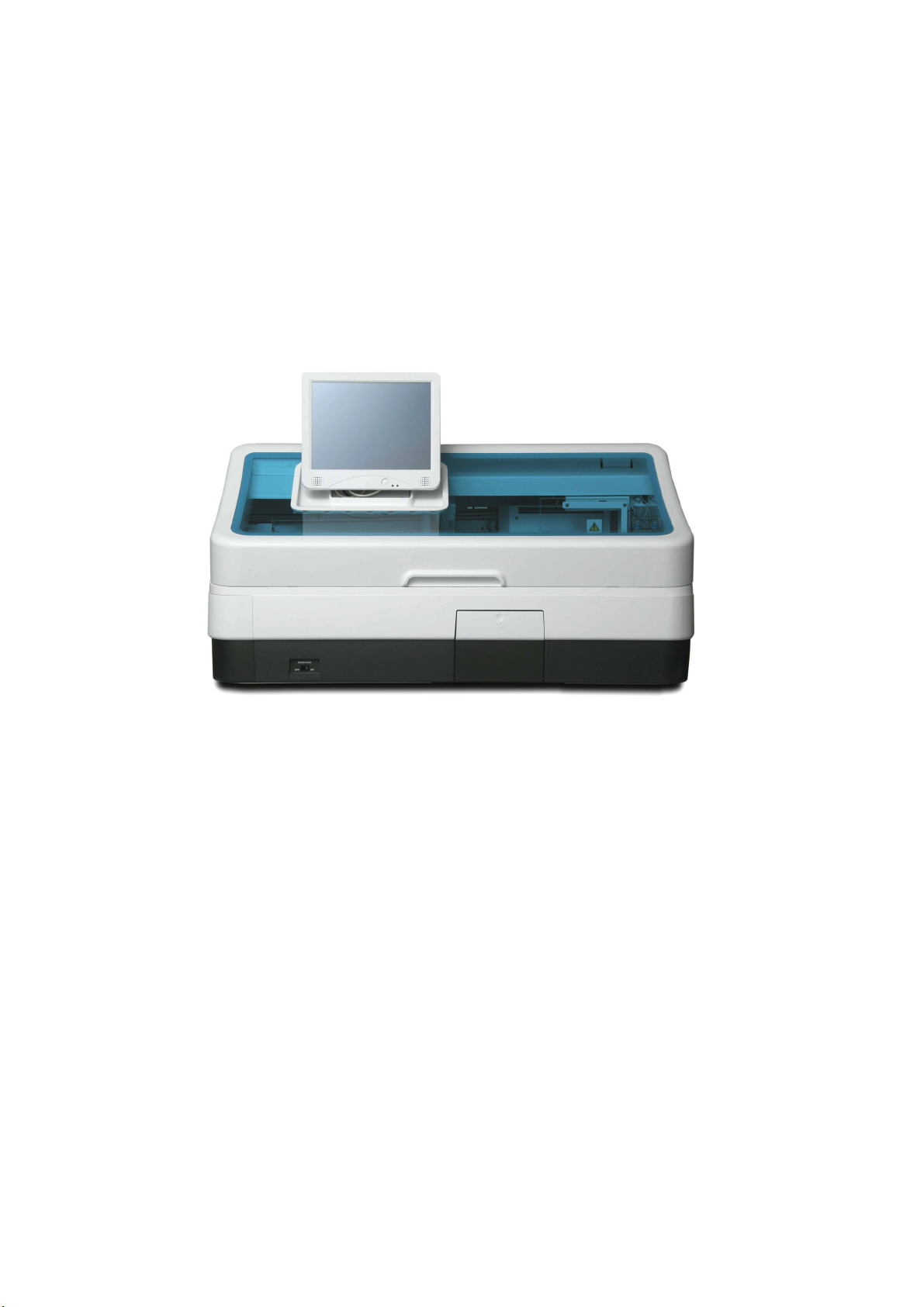
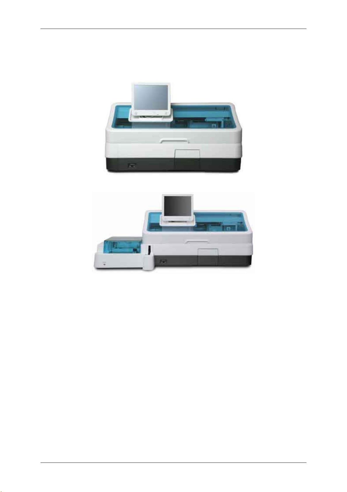
Figure 1.1-1 cobas e411 disk system
Figure 1.1-2 cobas e411 rack system
Version 1.0 – May 2006 1 - 1 Chapter 1.1
Page 17
RD/Hitachi cobas e411 Service Manual
1.1.2 System Introduction
The Roche Diagnostics cobas e411 Immunoassay System is a fully automated, software-controlled
system for immunoassay analysis. It is designed for both quantitative and qualitative in vitro
determinations using a large variety of tests for analysis.
To assist you in quickly identifying which component is specific to either the disk or rack system, one
of the following graphics appears to the right of the subsection header. If no graphic appears next to
the header, then that component is common to both systems.
Figure 1.1-3 Disk
Figure 1.1-4 Rack
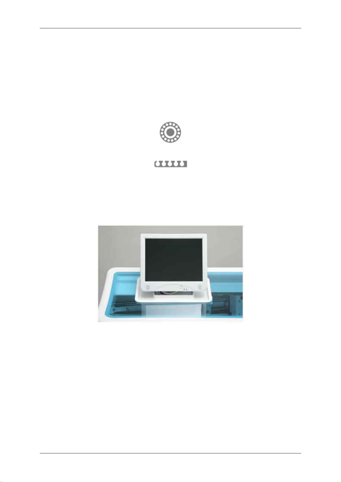
1.1.2.1 The Control Unit
The control unit of the e411 analyzer is a touchscreen, no-keyboard type computer, which is located
on the left-center of the analyzer unit. This monitor unit contains the controlling software and also has
an on-screen keyboard function.
Figure 1.1-5 Control unit
Version 1.0 – May 2006 1 - 2 Chapter 1.1
Page 18
RD/Hitachi cobas e411 Service Manual
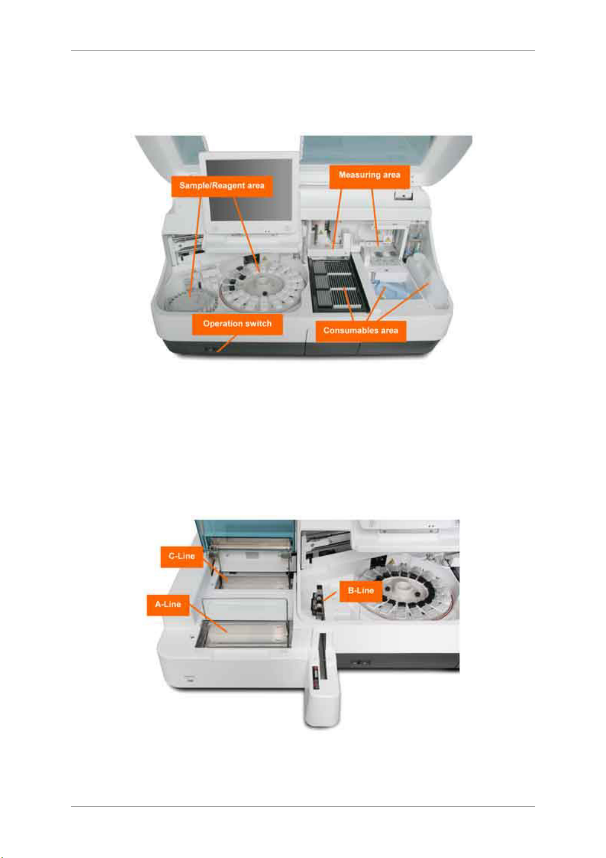
1.1.2.2 The Analyzer Unit
Figure 1.1-6
The analyzer unit on the disk system consists of the:
• sample/reagent area
• consumables area
• measuring area
• operation switch
The only difference on the rack system is in the sample area. The sample disk is replaced by a rack
sampling unit.
Refer to the photo below.
Figure 1.1-7
Version 1.0 – May 2006 1 - 3 Chapter 1.1
Page 19

RD/Hitachi cobas e411 Service Manual
1.1.2.3 Sample/Reagent Area
The sample/reagent area comprises the left half of the analyzer and consists of a sample disk or rack
sampler (rack system), rack bar code reader (rack system), sample/reagent (S/R) probe, bar code
reader, bar code card reading station, reagent disk, a cap open/close mechanism, a microparticle
mixer, probe/ mixer rinse station and sample/reagent (S/R) pipettor.
The sample disk accommodates up to 30 samples. The A-Line of the rack sampler accommodates 75
samples on a single tray (15 racks at a time; each rack with five positions) and 25 samples in the input
buffer for a total capacity of 100 samples. The reagent disk, temperature controlled at 20 ± 3 °C,
accommodates up to 18 reagent packs.
1.1.2.4 Consumables Area
The consumables area is on the right of the analyzer, consisting of three tip trays, three AssayCup
trays, a gripper unit, cup disposal opening, liquid waste container, solid waste tray and liner and
system water container.
1.1.2.5 Measuring Area
The measuring area includes the incubator, the sipper probe, sipper rinse station, system reagents
(ProCell and CleanCell), an aspiration station, sipper pipettor and the detection unit. The sipper probe
aspirates the incubated reaction mixture into the detection unit for result determination.
1.1.2.6 Operation Switch
The operation ON/OFF switch is located on the front left of the analyzer. In addition, there is a circuit
breaker for the analyzer located on the right side panel and a rack sampler circuit breaker located on
the left side of the rack sampler.
Version 1.0 – May 2006 1 - 4 Chapter 1.1
Page 20
RD/Hitachi cobas e411 Service Manual
1.1.3 Control Unit Components
The control unit consists of a color touchscreen monitor, host interface and external printer.
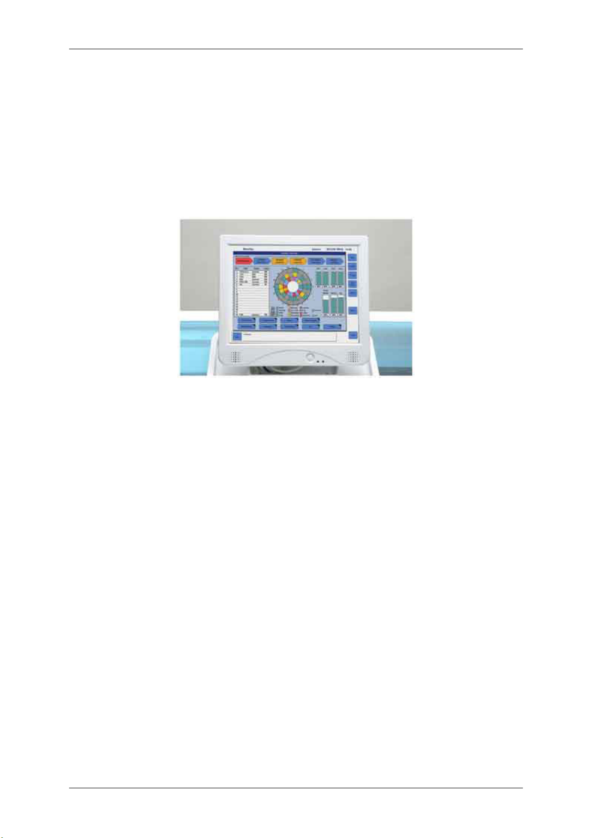
1.1.3.1 Touchscreen Monitor
The touchscreen monitor is located on the left-center of the analyzer and displays the software. For
details on the cobas e411 software, refer to the Software Guide.
Figure 1.1-8 Touchscreen monitor
Version 1.0 – May 2006 1 - 5 Chapter 1.1
Page 21
RD/Hitachi cobas e411 Service Manual
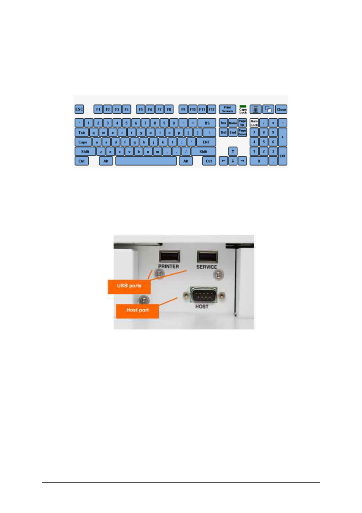
1.1.3.2 On-screen Keyboard
The e411 software has an on-screen keyboard. For details refer to the Software Guide.
Figure 1.1-9 On-screen keyboard
1.1.3.3 External Printer
The instrument uses an 80-column, graphics-capable, dot matrix printer.
The printer is connected to the analyzer via a USB port. The analyzer has two USB ports on its left
side.
Figure 1.1-10 Location of the USB ports and Host port
1.1.3.4 Host Interface
The instrument can be bidirectionally interfaced with a host computer.
Please refer the Host Interface manual in detail.
Version 1.0 – May 2006 1 - 6 Chapter 1.1
Page 22
RD/Hitachi cobas e411 Service Manual
1.1.4 Sample/Reagent Area Components
The sample/reagent area consists of a sample disk or rack sampler (rack system), rack ID bar code
reader (rack system), sample/reagent (S/R) probe, bar code reader, bar code card reading station,
reagent disk, cap open/close mechanism, microparticle mixer, probe/mixer rinse station and
sample/reagent (S/R) pipettor.
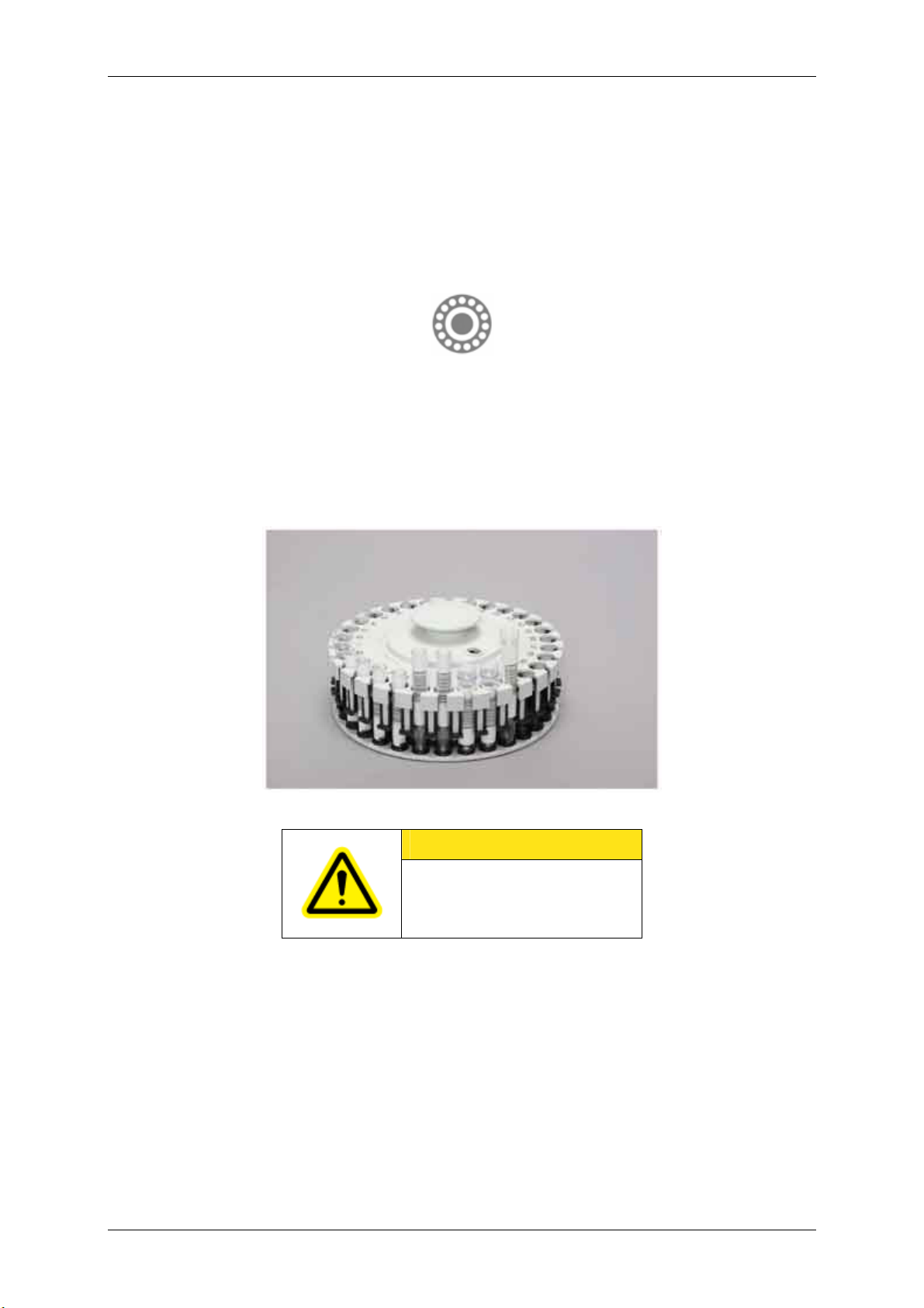
Figure 1.1-11 Sample Disk
The sample disk has 30 positions for samples, calibrators and controls. Patient samples may be
placed in either primary sample tubes or sample cups. Built-in adapters allow intermixing of different
size primary sample tubes.
Sample tubes that may be used are listed in chapter 2.7 Technical Data.
Sample cups [2 mL (Standard) Hitachi cups only] may be placed directly on the sample disk or on top
of 16 mm primary sample tubes.
Figure 1.1-12 Sample disk
CAUTION
Micro cups cannot be used on the
e411 analyzer!
Version 1.0 – May 2006 1 - 7 Chapter 1.1
Page 23
RD/Hitachi cobas e411 Service Manual
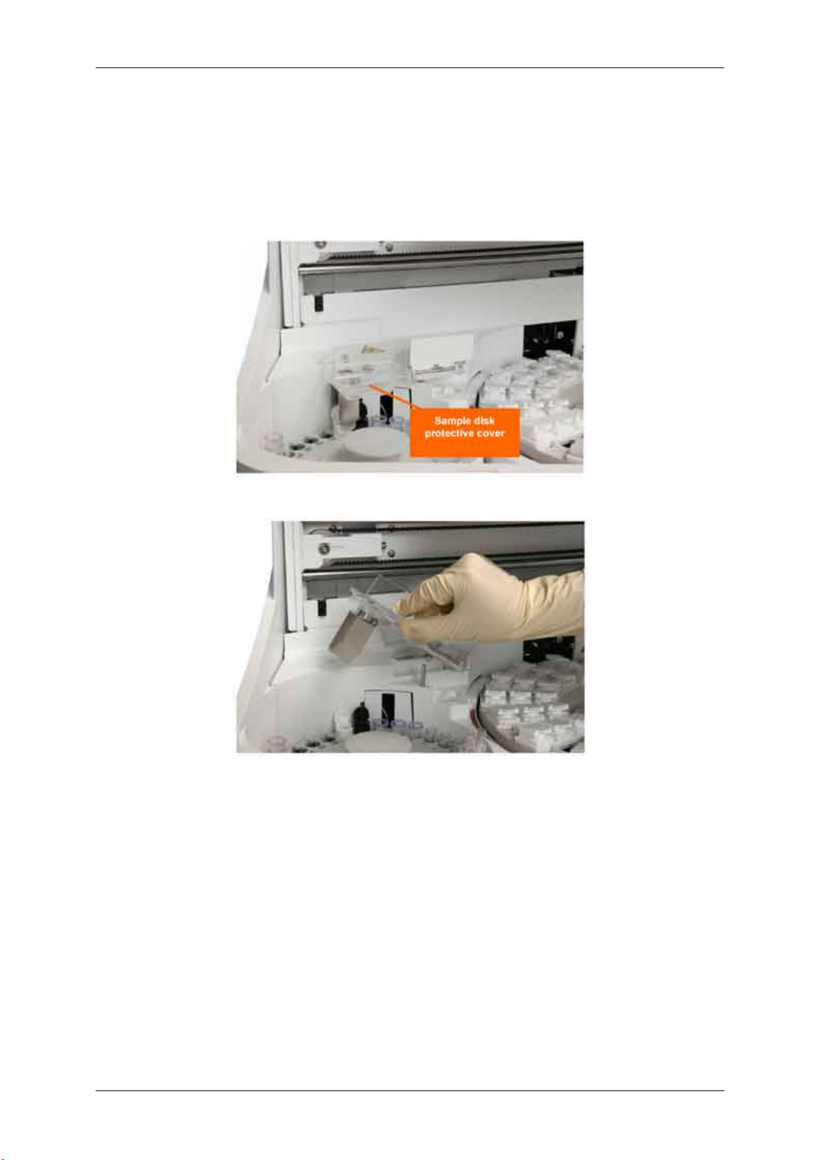
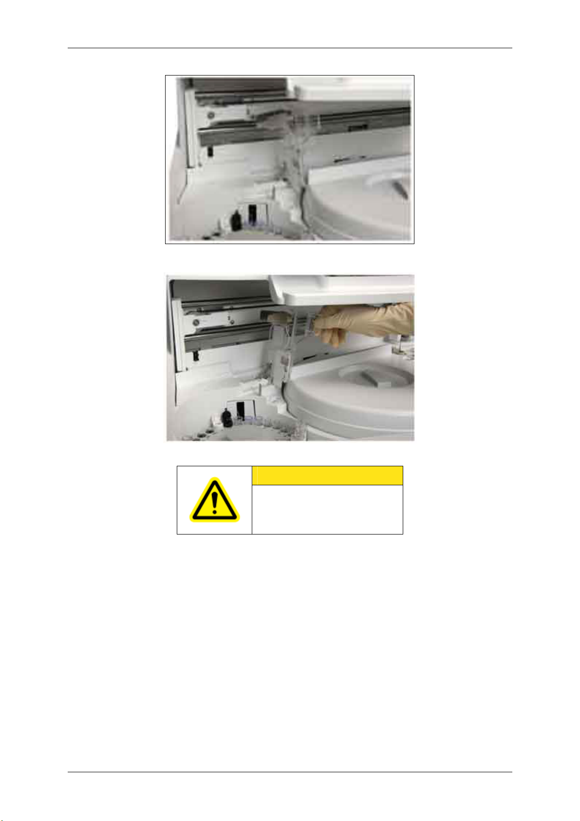
Note: How to raise the sample disk protective cover
To take out the sample disk, first you must raise the sample disk protective cover. The cover can be
held at a certain angle. To lay the cover down, release the hold by raising the cover up to its limit
angle. Be sure to lay it down before you start operation.
Figure 1.1-13 Sample disk protective cover
Figure 1.1-14 n Raising the sample disk protective cover
Version 1.0 – May 2006 1 - 8 Chapter 1.1
Page 24
RD/Hitachi cobas e411 Service Manual
Figure 1.1-15 Standing angle
Figure 1.1-16 Limit angle
CAUTION
Be sure to lay down the sample disk
protective cover before you start
operation.
Version 1.0 – May 2006 1 - 9 Chapter 1.1
Page 25
RD/Hitachi cobas e411 Service Manual
Figure 1.1-17
Rack Sampler
The rack sampler consists of an A-Line, B-Line, C-Line and STAT position.
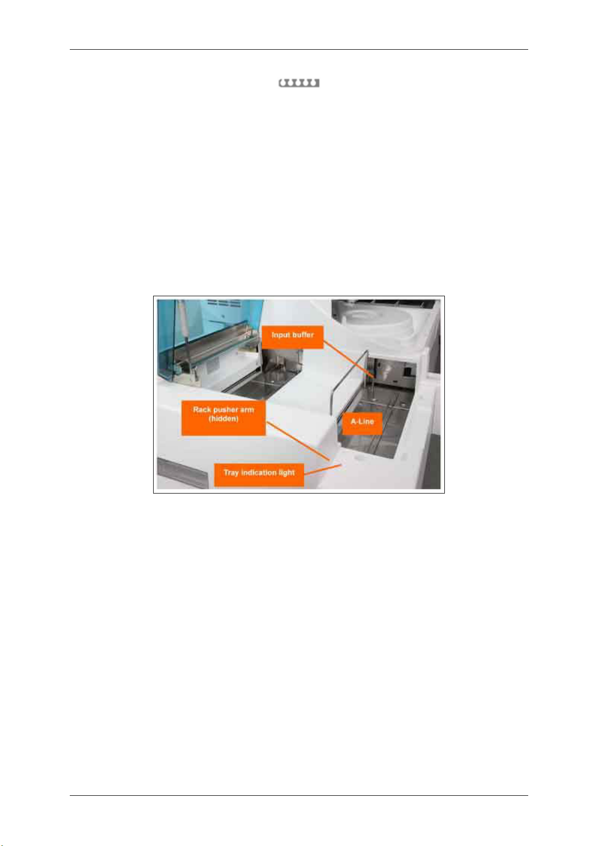
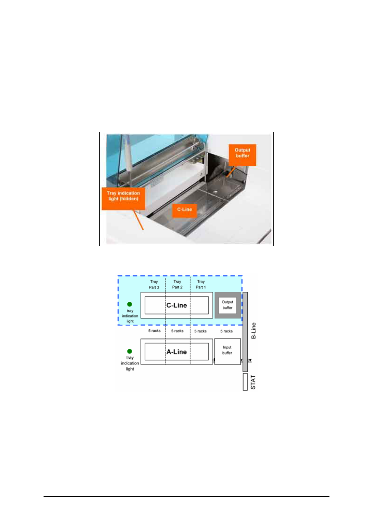
1.1.4.1 A-Line
Specimens are placed in 5-position sample racks and are loaded onto a tray. Once a tray is loaded,
additional racks can be added to the tray one at a time during Operation, provided the tray indication
light is green (ON). If the light is out (OFF), the pusher arm is preparing to move. The pusher arm is
located at the far left of the A-Line and pushes the sample racks forward and onto the B-Line.
The A-Line holds a tray that accommodates 15 racks at one time. Another five racks can be in the
input buffer. Therefore, you can have a total of 100 specimens loaded at any one time. Refer to the
photo and graphic below.
Figure 1.1-18
Version 1.0 – May 2006 1 - 10 Chapter 1.1
Page 26
RD/Hitachi cobas e411 Service Manual
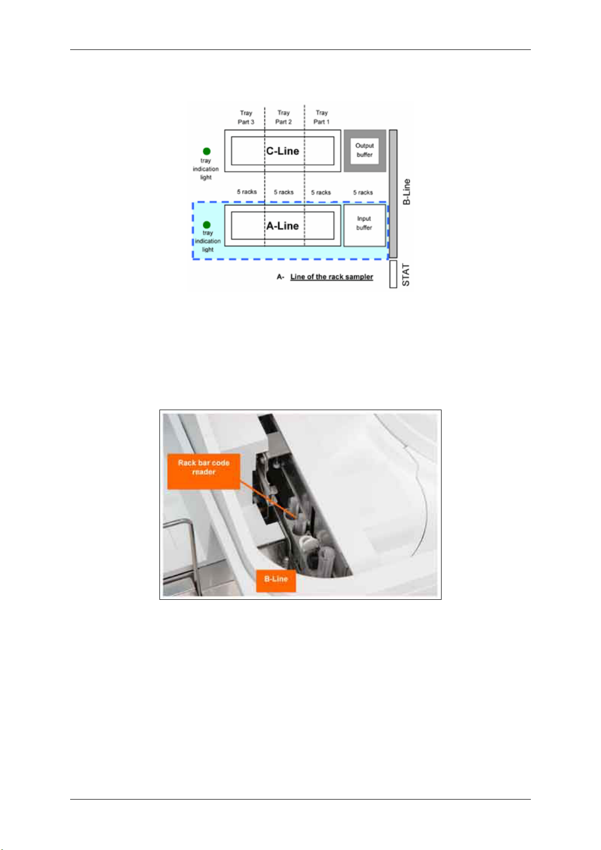
Figure 1.1-19
1.1.4.2 B-Line
The B-Line transports the sample racks, single file, first to the rack bar code reader. Here each
position in the rack is scanned for a sample bar code. After the last position is scanned, the bar code
reader scans the rack ID. After the last specimen is sampled, the rack is transferred via the output
buffer onto the tray on the C-Line. Refer to the photo and graphic below.
Figure 1.1-20
Version 1.0 – May 2006 1 - 11 Chapter 1.1
Page 27
RD/Hitachi cobas e411 Service Manual
Figure 1.1-21 B-Line of the rack sampler
1.1.4.3 Rack Bar Code Reader
The rack bar code reader reads both sample bar code labels and the rack bar code label. The bar
code reader is auto-discriminating, allowing the use of various types of bar codes during operation.
Bar code symbologies read include:
• NW7 (Codabar)
• Code 39
• Code 128
• Interleaved 2 of 5
Figure 1.1-22 Rack bar code reader
Version 1.0 – May 2006 1 - 12 Chapter 1.1
Page 28
RD/Hitachi cobas e411 Service Manual
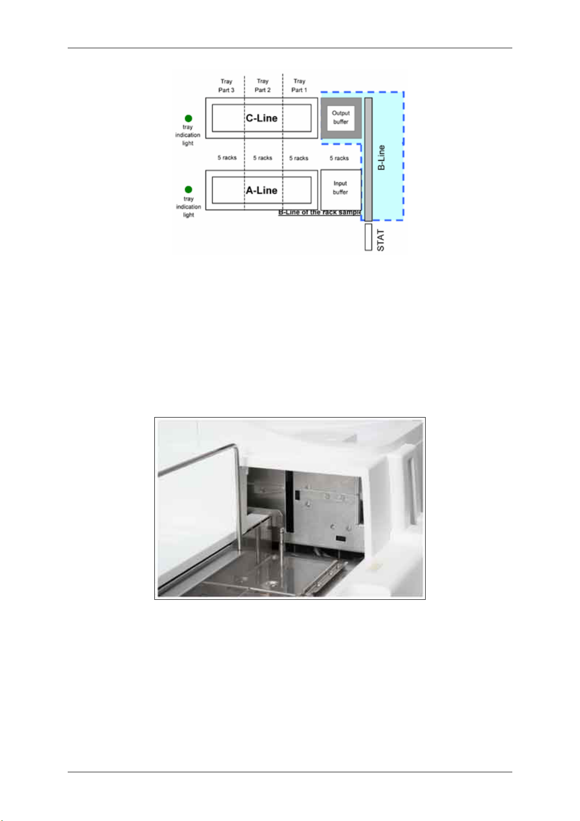
1.1.4.4 C-Line
Racks are off-loaded from the B-Line into the output buffer. If there is no tray, up to 5 racks can enter
the output buffer, thereafter the sampling procedure is stopped. When the sixth rack is moved into the
output buffer, a rack is pushed onto the tray on the C-Line. You can remove the tray from the C-Line
any time the tray indication light is green (ON). If the light is out (OFF), the system is preparing to push
a rack onto the C-Line tray. You cannot remove single racks from the C-Line. You must remove an
entire tray at one time.
Figure 1.1-23
Figure 1.1-24 C-Line of the rack sampler
If the tray is removed, the system continues to push racks into the output buffer. If the buffer fills and
there is no tray, the analyzer issues an alarm and stops sampling racks.
Version 1.0 – May 2006 1 - 13 Chapter 1.1
Page 29
RD/Hitachi cobas e411 Service Manual
Figure 1.1-25 Output buffer with racks
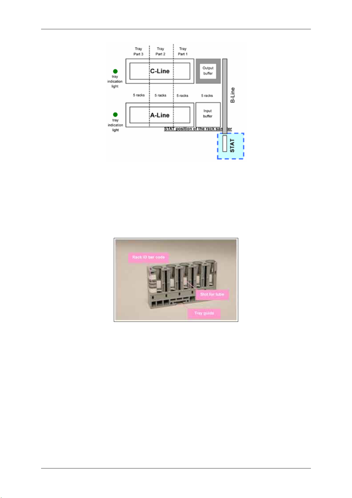
1.1.4.5 STAT Position
The STAT position is located at the front of the analyzer and is in line to feed directly onto the B-Line.
Place a rack in the position as directed on the label and press the STAT key. When the rack currently
being sampled is completed, the STAT rack is pushed onto the B-Line and is sent on to the rack bar
code reader and sampling position.
Figure 1.1-26
Version 1.0 – May 2006 1 - 14 Chapter 1.1
Page 30
RD/Hitachi cobas e411 Service Manual
Figure 1.1-27 STAT position of the rack sampler
1.1.4.6 Sample Rack
Sample cups, primary sample tubes, calibrator or control vials are placed in sample racks shown
below. Each sample rack holds a maximum of five samples. Each tube slot contains adapters that
allow the rack to hold different sizes of primary sample tubes. Each rack has a unique ID found on the
bar code label on the back end of the rack. This rack ID is read by the bar code reader and transferred
to the system. This ID appears on the screens in the software and on the reports.
Figure 1.1-28 Sample rack
1.1.4.7 Sample/Reagent (S/R) Probe
The sample/reagent probe is located on the back left wall of the analyzer and is mounted on an arm
(S/R arm) that moves horizontally between the sample and reagent disk. The probe uses disposable
tips to avoid sample carryover, and has liquid level and clot detection for accurate pipetting. Liquid
level detection is accomplished by capacitance measurement. Clot detection is accomplished by a
pressure transducer.
A new AssayTip is utilized with every new pipetting sequence. For example, TSH = 1 tip for R1, R2
and sample, then one new tip for microparticles. The tip is washed externally at the rinse station
between each aspiration. Additional tips are used for sample dilutions or pretreatment.
Version 1.0 – May 2006 1 - 15 Chapter 1.1
Page 31

RD/Hitachi cobas e411 Service Manual
Figure 1.1-29 S/R probe with tip
Note: Ensure that there is no foam on the surface of the sample.
Version 1.0 – May 2006 1 - 16 Chapter 1.1
Page 32

RD/Hitachi cobas e411 Service Manual
1.1.4.8 Bar Code Reader
During a sample scan, the bar code reader scans the information on the bar code-labeled primary
sample tubes, calibrators or controls, and transmits it to the software. During a reagent scan, the
reader rotates to the reagent disk side to read the 2-dimensional bar code labels on the reagent packs.
The bar code reader is located toward the back wall of the analyzer.
Figure 1.1-30 On the disk system:
• it can be seen when either the sample disk or reagent disk is removed.
• to read bar code labels, the bar code reader rotates between the sample and reagent disks, and
the card reading station.
Figure 1.1-31
On the rack system:
• it can only be seen when the reagent disk is removed.
• to read bar code labels, the bar code reader rotates between the reagent disk and the card
reading station.
• A second bar code reader scans sample bar codes and rack ID bar codes.
The bar code reader is auto-discriminating, allowing the use of various types of bar codes during
operation. In addition, this bar code reader also reads PDF417.
Note: PDF417 can only be used for reagent bar codes and bar code cards.
Figure 1.1-32 Bar code reader (sample disk side)
Version 1.0 – May 2006 1 - 17 Chapter 1.1
Page 33

RD/Hitachi cobas e411 Service Manual
Figure 1.1-33 Bar code reader (reagent disk side)
1.1.4.9 Bar Code Card Reading Station
At this station, the bar code reader scans calibrator and control information from the calibrator or
control bar code card. These cards are packed in calibrator or control kits.
Figure 1.1-34
On the disk system:
• it is located between the sample disk and reagent disk.
Figure 1.1-35
On the rack system:
• it is located to the back left of the reagent disk.
Figure 1.1-36 Bar code card reading station
Version 1.0 – May 2006 1 - 18 Chapter 1.1
Page 34

RD/Hitachi cobas e411 Service Manual
1.1.4.10 Reagent Disk
The reagent disk contains 18 positions for assays, diluent or pretreatment reagent. These 18 positions
can be used in any combination, with the following restrictions: max. 18 assays, max. 8 diluents, max.
9 pretreatments.
The reagent disk is temperature controlled at 20 ± 3 °C.
Note: Diluents or pretreatment reagents can be placed in ANY position on the reagent disk. More
than one reagent pack can be loaded on the reagent disk for each test.
Figure 1.1-37 Reagent disk
1.1.4.11 Reagent Cap Open/Close Mechanism
To prevent reagents from evaporating, and to promote ease of use for the operator, the reagent disk
utilizes a reagent cap open/close mechanism during reagent pipetting. The mechanism is located on
the back wall of the reagent disk compartment and emerges when reagents need to be opened or
closed. Caps are opened prior to pipetting or mixing the specific reagent (e.g., M, R1 or R2) and are
closed when pipetting or mixing for the specific reagent (e.g., M, R1 or R2) is completed.
Figure 1.1-38 Reagent cap open/close mechanism
Version 1.0 – May 2006 1 - 19 Chapter 1.1
Page 35

RD/Hitachi cobas e411 Service Manual
1.1.4.12 Microparticle Mixer
The mixer is utilized to mix the microparticles to ensure a homogeneous suspension before aspiration.
The mixer is located to the right of the reagent disk. In its home position, it occupies the space directly
to the left of the S/R probe.
Figure 1.1-39 Microparticle mixer
1.1.4.13 Probe/Mixer Rinse Station
The rinse station rinses the AssayTip or mixer externally with system water between aspirations, or
before and after microparticle mixing. The rinse station is located below the S/R probe and mixer
when the probe is in its Stand-by position and the mixer is in its home position.
Figure 1.1-40 Rinse station
Version 1.0 – May 2006 1 - 20 Chapter 1.1
Page 36

RD/Hitachi cobas e411 Service Manual
1.1.4.14 Sample/Reagent (S/R) Pipettor
The S/R pipettor is located on the back right of the analyzer. The pipettor is filled with system water
and uses positive displacement to aspirate and dispense from the S/R probe.
Figure 1.1-41 Sample/reagent pipettor
Version 1.0 – May 2006 1 - 21 Chapter 1.1
Page 37

RD/Hitachi cobas e411 Service Manual
1.1.5 Consumables Area Components
The consumables area consists of three AssayCup trays, three tip trays, gripper, incubator, cup
disposal opening, pipetting station, liquid waste container, system water container and solid waste tray
and liner.
One tip tray holds up to 120 tips, and one cup tray holds up to 60 cups. Therefore, a total of 360 tips
and 180 cups can be placed on the analyzer.
Figure 1.1-42 Tip tray and cup tray
Version 1.0 – May 2006 1 - 22 Chapter 1.1
Page 38

RD/Hitachi cobas e411 Service Manual
1.1.5.1 Gripper
The gripper can move in three directions:
• X (left and right)
• Y (forward and back)
• Z (up and down)
It is also equipped with gripping fingers for gripping a tip or AssayCup. The gripping fingers grip a tip
from the tip tray, or a cup from the cup tray and deliver it to the pipetting station. Then, at the
appropriate time, the gripper moves the AssayCup to the incubator, then to the aspiration station, and
finally to the cup disposal opening.
During operation, the analyzer starts utilizing tips and cups from tray 1, position 1. As soon as tray 1 is
empty, the analyzer starts using tray 2. As soon as tray 2 is empty, the analyzer continues with tray 3.
When tray 3 is empty, the analyzer returns to tray 1, if a new tray has been reloaded.
Figure 1.1-43 Gripper and trays
1.1.5.2 Cup Disposal Opening
AssayCups are discarded through a cup opening located directly to the left of the incubator.
Figure 1.1-44 Cup disposal opening
Version 1.0 – May 2006 1 - 23 Chapter 1.1
Page 39

RD/Hitachi cobas e411 Service Manual
1.1.5.3 Pipetting Station
A five position pipetting station is located to the upper left of the incubator. AssayCups and tips are
moved by the gripper to this location for sample and reagent pipetting, sample dilution and sample
pretreatment. The AssayTips are discarded at the tip eject station at the far right of the station.
Positions 1 and 2 are used for tips and positions 3 and 4 are used to hold cups for dilution or
pretreatment. Position 5 is the position where the S/R probe pipettes sample and reagent.
Figure 1.1-45 Pipetting station
1.1.5.4 System Water Container
The system water container is located in front of the pipettors and to the right of the liquid waste
container. It holds three liters of system water. An alarm is issued when the system water container is
empty. A float mechanism sensor located beneath the aspiration inlet, triggers the alarm on the
System Overview screen.
Note: Removing the system water container while the analyzer is in Operation causes the
analyzer to enter P. Stop status.
Figure 1.1-46 System water container
Version 1.0 – May 2006 1 - 24 Chapter 1.1
Page 40

RD/Hitachi cobas e411 Service Manual
1.1.5.5 Liquid Waste Container
The liquid waste container is located in front of the ProCell and CleanCell reagents. It holds four liters
of waste and issues an alarm when approximately three-quarters full. The alarm is triggered by a
weight-sensitive mechanism that activates a photosensor located in the compartment holding the
container. An alarm is also issued when the container is improperly positioned. This alarm is triggered
by a plate mechanism that activates a photosensor located at the front of the compartment.
Note: Removing the liquid waste container while the analyzer is in Operation or an improperly
positioned container causes the analyzer to enter E. Stop status.
Figure 1.1-47 Liquid waste container
Version 1.0 – May 2006 1 - 25 Chapter 1.1
Page 41

RD/Hitachi cobas e411 Service Manual
1.1.5.6 Solid Waste Tray and Liner
The solid waste tray and liner is located behind the front access door on the analyzer. Used
AssayCups and tips are discarded into the waste tray during operation.
A disposable liner (Clean-Liner) made of polystyrene is placed inside the solid waste tray. The CleanLiner has a sliding cover to reduce potential splashing and to prevent tips and cups from falling out of
the tray upon removal from the analyzer. During operation, the sliding cover must be open. The tray
shakes periodically during operation so that used tips and cups do not accumulate at one end of the
tray.
An alarm is issued when either the tray is full (max. 1100 tips and cups) or if the tray and liner are
missing. The presence of a tray is monitored by a photosensor.
Note: Removing the solid waste tray while the analyzer is in Operation causes the analyzer to
enter E. Stop status.
Figure 1.1-48 Solid waste tray and liner
Version 1.0 – May 2006 1 - 26 Chapter 1.1
Page 42

RD/Hitachi cobas e411 Service Manual
1.1.6 Measuring Area Components
The measuring area includes the incubator, aspiration station, sipper probe, sipper rinse station,
sipper pipettor, system reagents (ProCell and CleanCell) and the detection unit.
1.1.6.1 Incubator
The incubator is maintained at a specific temperature (37.0 °C ± 0.3° C) for the reaction of the sample
and the reagents that have been dispensed into a cup. The incubator is equipped with 32 positions.
When an assay is ready for measurement, the AssayCup is transferred by the gripper to the aspiration
station, and the sipper probe aspirates the reaction mixture for measurement. The aspiration station,
located in the lower right corner of the incubator, is not temperature controlled.
Figure 1.1-49 Incubator
Version 1.0 – May 2006 1 - 27 Chapter 1.1
Page 43

RD/Hitachi cobas e411 Service Manual
1.1.6.2 Sipper Probe
The sipper probe aspirates the reaction mixture into the measuring cell. ProCell and CleanCell are
also aspirated by the sipper probe. The sipper probe is located to the right of the incubator. The sipper
rinse station externally washes the sipper probe with system water between measurements. When the
sipper probe is in its Stand-by position, the probe is located directly above the rinse station.
Figure 1.1-50 Sipper probe and rinse station
Version 1.0 – May 2006 1 - 28 Chapter 1.1
Page 44

RD/Hitachi cobas e411 Service Manual
1.1.6.3 Sipper Pipettor
The sipper pipettor is located directly to the right of the sample/reagent syringe. They use positive
displacement of water to aspirate and dispense from the sipper probe.
Figure 1.1-51 Sipper pipettor
Version 1.0 – May 2006 1 - 29 Chapter 1.1
Page 45

RD/Hitachi cobas e411 Service Manual
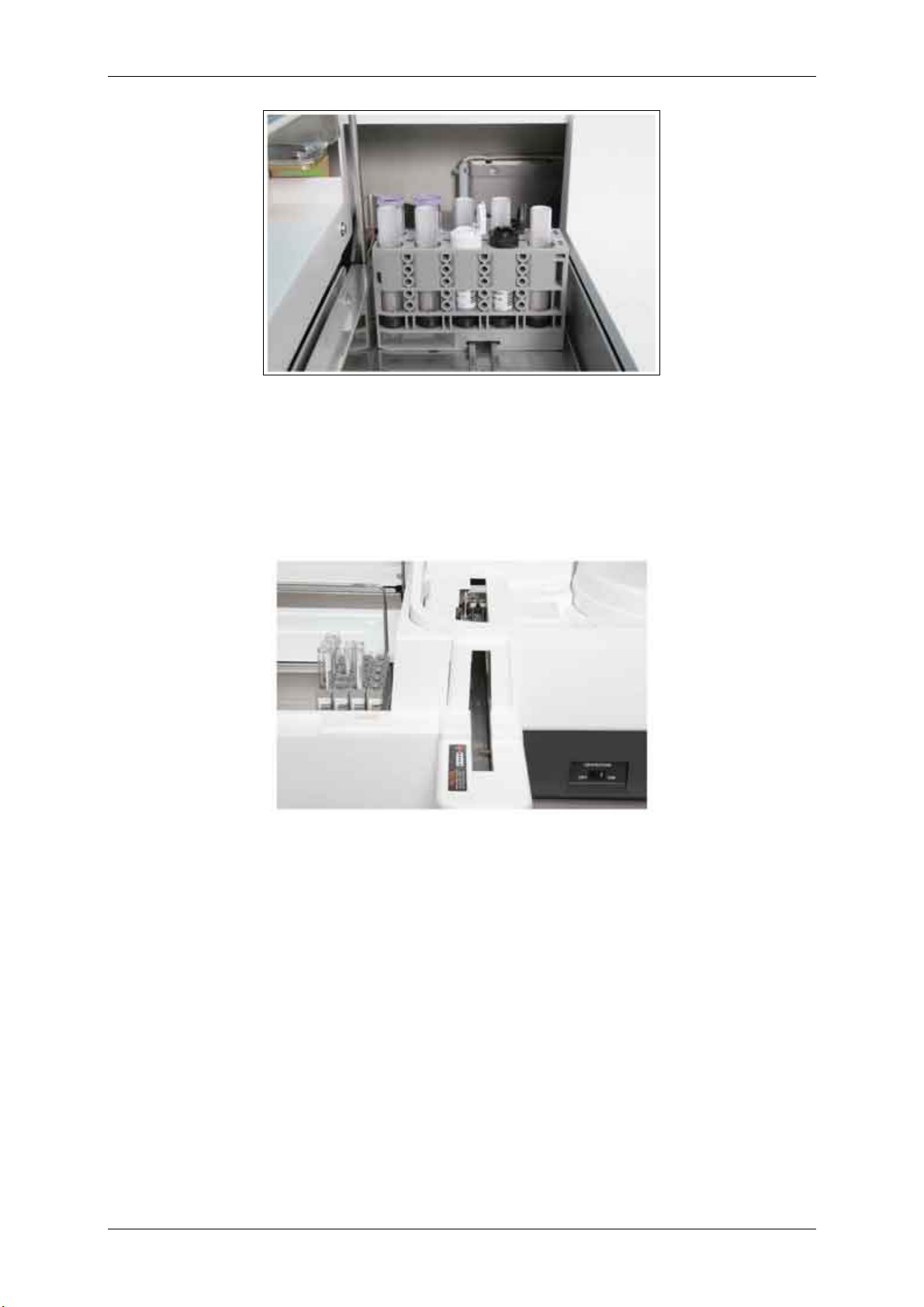
1.1.6.4 System Reagents (ProCell and CleanCell)
ProCell and CleanCell are located behind the liquid waste container. ProCell is the buffer solution
containing tripropylamine (TPA). These bottles are identified with white caps.
CleanCell is the cleaning solution used to clean the measuring cell after measurement. CleanCell
bottles are identified with black caps.
The reagent compartment is keyed to ensure the correct reagent is placed in the proper position. Two
bottles of each reagent are stored on the analyzer, temperature controlled at 28.0 °C ± 2.0 °C.
Figure 1.1-52 ProCell (PC) and CleanCell (CC)
When starting from Stand-by, the sipper probe always attempts to first use ProCell and CleanCell from
bottle set 2. If the quantity is insufficient, bottle set 1 is used. When starting from S. Stop or R. Stop,
the bottle set in use when the analyzer was previously in Operation is pipetted.
The analyzer can operate with one bottle set of ProCell and CleanCell reagent, but they must be
placed in positions 1 & 2 or 3 & 4. Refer to the photograph above.
Note:
Note:
To have access to system reagent bottles, you must open the sipper safety cover. To open
this cover, push the cover’s metal part as shown in the picture below to release the hold. To
close the cover, push the same part until a click is heard.
How to open the sipper safety cover
Figure 1.1-53 Opening/closing the sipper safety cover (Push the circled point)
Version 1.0 – May 2006 1 - 30 Chapter 1.1
Page 46

RD/Hitachi cobas e411 Service Manual
Figure 1.1-54 Sipper safety cover (when opened)
CAUTION
• Do not open the sipper safety cover while the analyzer is in Operation.
Otherwise, the operation will stop.
• Be sure to close the cover after you placed/replaced system reagents, or
performed maintenance. Otherwise, the instrument will not operate.
Version 1.0 – May 2006 1 - 31 Chapter 1.1
Page 47

RD/Hitachi cobas e411 Service Manual
1.1.6.5 Detection Unit
The detection unit is the core of the cobas e411 system. The detection unit contains the
photomultiplier tube, peltier, flow-through measuring cell, magnet drive assembly and an amplifier
circuit board. The temperature is maintained at 28.0 °C ± 0.3 ° C.
Figure 1.1-55 Measuring cell of the detection unit
Version 1.0 – May 2006 1 - 32 Chapter 1.1
Page 48

RD/Hitachi cobas e411 Service Manual
1.1.7 Power Components
1.1.7.1 Operation Switch
The operation switch is located on the lower left front side of the analyzer. Use this switch to turn OFF
the analyzer to perform certain maintenance procedures or when the system is not in use for extended
periods of time (e.g., overnight).
Provided the circuit breaker is ON, the reagent disk and system reagent compartment temperatures
are maintained while the operation switch is OFF.
Figure 1.1-56 Operation ON/OFF switch
1.1.7.2 Circuit Breaker
The circuit breaker is located on the right side panel of the analyzer above the power supply cord. The
circuit breaker controls the power supplied to the temperature controlled reagent compartments when
the operation switch is OFF. The circuit breaker must be in the I (ON) position whenever reagents are
stored on the analyzer and to maintain liquid in the measuring cell.
When connecting or disconnecting the host cable, power the analyzer off at the circuit breaker only
Note: To disconnect the analyzer from the supply source, the circuit breaker must be in the O
(OFF) position and the power cord must be removed.
Figure 1.1-57 Circuit breaker
Version 1.0 – May 2006 1 - 33 Chapter 1.1
Page 49

RD/Hitachi cobas e411 Service Manual
Figure 1.1-58
1.1.7.3 Rack Circuit Breaker
There is a circuit breaker located on the left side of the rack sampler. This controls power to the
sampler unit. The circuit breaker should be kept in the I (ON) position at all times. Use the operation
switch to power ON and OFF the rack system.
Note: To disconnect the analyzer from the supply source, the circuit breaker must be in the O
(OFF) position and the power cord must be removed.
Figure 1.1-59 Rack circuit breaker
Version 1.0 – May 2006 1 - 34 Chapter 1.1
Page 50

RD/Hitachi cobas e411 Service Manual
1.1.8 Mechanical Theory
1.1.8.1 Introduction
The cobas e411 analyzer automates the immunoassay reactions utilizing electrochemiluminescence
(ECL). These reaction methods are described in detail in Chapter 4, ECL Technology. The individual
test steps and how the system performs the necessary procedures are discussed here.
1.1.8.2 Test Protocols
There are 28 test protocols or test steps that can be used on the analyzer. These protocols are
predefined by Roche Diagnostics for each test and cannot be changed by the operator.
1.1.8.3 General Assay Sequence
An immunological ECL test is made up of various pipetting steps, at least one incubation period and a
measurement step. Generally at least three test components (sample, reagent and microparticles) are
pipetted into an AssayCup. After the appropriate incubation period, the reaction mixture is aspirated
into the measuring cell where the measurement process takes place. Each of the required pipetting
cycles is performed within a defined period (42 seconds).
The number of pipetting steps, as well as the make up of the reaction mixture are dependent on the
test method (1 or 2 step test). For some methods, predilution with diluent and/or pretreatment with a
special reagent is necessary. Thus the number of pipetting steps is increased.
After each pipetting step the sample/reagent (S/R) probe tip is cleaned and, if necessary, the
microparticle mixer and sipper probe are also cleaned.
The following steps apply in principle to all methods. The sequence of the individual processes differ
from test to test.
1.1.8.4 Preparative Operations
Once the analyzer's power is switched ON, the initialization process is started. During initialization, the
mechanisms are reset to their home positions.
1.1.8.5 Run Operation
After the appropriate test selections are made in the software for patient samples, operation is started
according to the predetermined test protocol for each assay selected. Initially, at least one reagent (R1
or R2) and the sample or microparticles (M) are aspirated one after another by the S/R probe. After
each aspiration, the outside of the S/R probe tip is cleaned at the rinse station. The sample and
reagents are dispensed into a new AssayCup and the AssayTip is ejected into the solid waste tray.
For some tests that require sample dilution or pretreatment, diluent or pretreatment reagent is pipetted
together with sample into an AssayCup. An aliquot of the diluted/pretreated sample is then dispensed
with reagent into a second AssayCup. Therefore, certain tests with predilution/pretreatment may
require two or more AssayCups.
1.1.8.6 First Incubation at 37 °C
The incubation times are 4.5 or 9 minutes long, depending on the test. Some tests require only two
incubation periods, whereas tests with pretreatment tests can require three incubation periods. During
the incubation step(s) the immune complex products are formed.
Version 1.0 – May 2006 1 - 35 Chapter 1.1
Page 51

RD/Hitachi cobas e411 Service Manual
1.1.8.7 Additional Reagent Pipetting
Some assays (usually those with multiple incubation steps) require additional reagent pipetting. As in
the initial reagent pipetting step, a new pipette tip is picked up prior to reagent aspiration. The S/R
probe tip is washed at the rinse station after each liquid aspiration. The liquid is then dispensed into
the corresponding AssayCup where the sample and other liquids were dispensed in the first pipetting
step.
The probe rises while dispensing the reaction mixture back into the cup, thereby mixing the solution
and accelerating the reaction in the cup. The pipette tip is ejected into the solid waste tray when
pipetting is complete.
1.1.8.8 Second Incubation at 37 °C
If necessary, a second incubation step (4.5 or 9 minutes) occurs.
If using a pretreatment assay, the second incubation is similar to that described above for "First
Incubation at 37 °C".
1.1.8.9 Additional Reagent Pipetting (Pretreatment assays)
For pretreatment assays, reagent pipetting similar to that described above for “Additional Reagent
Pipetting” occurs.
1.1.8.10 Third Incubation at 37 °C (Pretreatment assays)
If necessary, a third incubation step (9 minutes) occurs for pretreatment assays.
1.1.8.11 Reaction Mixture Aspiration and Measurement
In this process the sipper probe first aspirates ProCell (tripropylamine solution, TPA) to prepare the
measuring cell. Then, the sipper probe aspirates the reaction mixture from the AssayCup and
transfers it to the measuring cell. The sipper probe is washed at the rinse station and ProCell is
aspirated again to rinse away the unbound reagent and sample constituents. Next, the ECL reaction in
the measuring cell occurs.
1.1.8.12 Measuring Cell Cleaning
Once the measurement is complete, the measuring cell is cleaned with CleanCell and prepared for a
new measurement process.
It takes 42 seconds (one pipetting cycle) from the aspiration of the reaction mixture by the sipper
probe until the measuring cell is filled with ProCell and ready for the next sample.
1.1.8.13 Finalization
30 Minutes after documentation of the last result, the sipper pipettor flushes system water through the
sipper probe, and then fills the measuring cell with ProCell before the analyzer returns to Stand-by.
After this procedure periodically all 30 minutes the waste pump of the S/R rinse station is running for 2
seconds (waste consumption approx. 12 mL). This procedure will be stopped after you switch off the
operation switch.
Version 1.0 – May 2006 1 - 36 Chapter 1.1
Page 52

RD/Hitachi cobas e411 Service Manual
1.1.8.14 Operation Flow in Analysis
An operational flow chart is shown below.
Figure 1.1-60 Operational flow chart
Version 1.0 – May 2006 1 - 37 Chapter 1.1
Page 53

RD/Hitachi cobas e411 Service Manual
1.1.9 Detailed Assay Sequence
The mechanical process of the instrument is described below using a sandwich test, TSH, as an
example. This example assumes that the reagent pack was already registered by the analyzer and
does not need calibration. All results are calculated based on an existing lot calibration.
1.1.9.1 Preoperation Steps
When START (the Start Conditions screen) is pressed from Stand-by, the following preoperative steps
occur.
A. The analyzer resets all mechanisms to their respective home positions. Next, the S/R pipettor
primes the S/R probe.
B. The gripper checks for a tip in position number 1 of the tip trays. If this position is empty, the gripper
remembers where it last left off and checks that position. If this position is empty, the gripper considers
the whole tray empty and the System Overview screen is updated accordingly.
Note: If the analyzer is in S. Stop, the gripper remembers where it last left off and checks for a tip
in that position.
1. During the tip check, the S/R probe is checked for the presence of a tip. The probe moves to the
tip eject station and performs the movements to eject a tip. If a tip is present it is ejected.
2. After the tip check is complete, the AssayCups are checked in the same manner. During the cup
check, the analyzer finishes priming the probes.
3. Next, the gripper checks the last three of the five positions on the pipetting station. If a cup is
present, the analyzer goes through the steps of a cup disposal. The gripper places a tip in position
1 of the pipetting station. Then, the S/R probe picks up the tip in position 1 of the pipetting station.
The S/R probe descends into the AssayCup and attempts to aspirate any possible liquid from the
cup. The gripper picks up the cup and discards it into the cup disposal opening. As the cup is
disposed, the S/R probe moves to the rinse station and dispenses any aspirated liquid. The tip is
then washed and discarded.
4. The gripper moves to the incubator where it checks all 32 incubator positions. If a cup is present,
the gripper moves the cup to position 5 on the pipetting station and uses the same procedure
listed in step 3 to discard the cup.
5. The S/R probe tip is ejected after all the incubator positions are checked.
Figure 1.1-61
Dispense Reagent 1, Reagent 2 and Sample
A TSH sample is present on position 1 of the sample disk.
1. After preoperation functions are complete, the gripper takes a tip from the tip tray and transports it
to position 1 of the pipetting station. The gripper returns to its Stand-by position.
2. The sample disk rotates until position 1 is in the sampling position.
3. The S/R probe moves to position 1 of the pipetting station, descends to obtain the tip, rises and
returns to its Stand-by position.
4. During this time, the reagent disk rotates until the TSH reagent pack is at the cap open/close
mechanism. The mechanism moves forward and opens the caps on the reagent pack. The disk
rotates again to move the TSH reagent to the R1 position.
5. The S/R probe moves from its Stand-by position to the R1 aspiration position. While activating
liquid level detection, the probe descends until it is 2 mm below the reagent surface and aspirates
60 µL of R1.
Version 1.0 – May 2006 1 - 38 Chapter 1.1
Page 54

RD/Hitachi cobas e411 Service Manual
Note: The lowest allowable point the S/R probe can descend to is 1.3 mm above the bottom of the
reagent pack.
Figure 1.1-62
While aspirating R1, the gripper puts another tip in position 1 of the pipetting station.
6. If the S/R probe does not detect liquid during descent, no reagent aspiration can occur, an alarm
is generated.
7. After R1 aspiration, the S/R probe rises and moves to the rinse station. To prevent the aspirated
R1 from contacting the water in the rinse station, the probe aspirates 10 µL of air. The rinse
station externally washes the tip.
8. During step 7, the reagent disk rotates until the TSH reagent pack is in the R2 position.
9. The S/R probe moves from the rinse station to the R2 position while aspirating another 10 µL of
air. This air layer prevents R1 from mixing with R2. While activating liquid level detection, the
probe descends until it is 2 mm below the reagent surface and aspirates 50 µL of R2. While
aspirating R2 the gripper moves an AssayCup to position 5 of the pipetting station.
10. Upon completion of R2 aspiration, the S/R probe rises and moves to the rinse station. To prevent
the aspirated R2 from contacting the water in the rinse station, the probe aspirates another 10 µL
of air. The rinse station externally washes the tip.
11. After R2 aspiration, the reagent disk rotates until the TSH reagent pack is at the cap open/close
mechanism. The mechanism moves out and closes the caps.
12. The S/R probe moves from the rinse station to the sampling position while aspirating another 10
µL of air. While activating liquid level detection, the probe descends until it is 2 mm below the
sample surface and aspirates 50 µL of sample. During sample aspiration, clot detection is
activated.
Version 1.0 – May 2006 1 - 39 Chapter 1.1
Page 55

RD/Hitachi cobas e411 Service Manual
Figure 1.1-63
Figure 1.1-64
Note: Depending on the sample volumes and the type of vials used (e.g. primary sample tube or
sample cup), the sample/reagent (S/R) probe can, when necessary, be lowered further to
prevent air being aspirated. With some low capacity vials, the inside diameter is relatively
small, which means the level of the liquid sinks when the liquid is being aspirated.
13. The S/R probe moves from the sampling position to position 5 of the pipetting station. The probe
descends until the tip reaches 2 mm below where the calculated level of the reaction mixture
surface should be and dispenses the sample, R2 and R1. The probe's downward displacement is
determined by calculating the reaction mixture volume for the sample and utilizing downward
displacement tables in the software. The probe does not rise during dispense.
14. After dispense, the S/R probe moves to the tip eject position and ejects the tip.
Version 1.0 – May 2006 1 - 40 Chapter 1.1
Page 56

RD/Hitachi cobas e411 Service Manual
Figure 1.1-65
Dispense Reagent 1, Reagent 2 and Sample
A TSH sample is present on position 1 of the sample rack.
1. After preoperation functions are complete, the gripper takes a tip from the tip tray and transports it
to position 1 of the pipetting station. The gripper returns to its Stand-by position.
2. The pusher arm pushes the racks in the A-Line forward to the B-Line. The arm returns to its home
position. The first rack loads on the B-Line.
3. As the rack incrementally moves on the B-Line, the rack bar code reader scans all five rack
positions and rack ID. When scanning is complete, position 1 of the rack is in the sampling
position.
4. The S/R probe moves to position 1 of the pipetting station, descends to obtain the tip, rises and
returns to its Stand-by position.
5. During this time, the reagent disk rotates until the TSH reagent pack is at the cap open/close
mechanism. The mechanism moves forward and opens the caps on the reagent pack. The disk
rotates again to move the TSH reagent to the R1 position.
6. The S/R probe moves from its Stand-by position to the R1 aspiration position. While activating
liquid level detection, the probe descends until it is 2 mm below the reagent surface and aspirates
60 µL of R1.
Figure 1.1-66
Note: The lowest allowable point the S/R probe can descend to is 1.3 mm above the bottom of the
reagent pack.
While aspirating R1, the gripper puts another tip in position 1 of the pipetting station.
7. If the S/R probe does not detect liquid during descent, no reagent aspiration can occur, an alarm
is generated.
8. After R1 aspiration, the S/R probe rises and moves to the rinse station. To prevent the aspirated
R1 from contacting the water in the rinse station, the probe aspirates 10 µL of air. The rinse
station externally washes the tip.
9. During step 8, the reagent disk rotates until the TSH reagent pack is in the R2 position.
10. The S/R probe moves from the rinse station to the R2 position while aspirating another 10 µL of
air. This air layer prevents R1 from mixing with R2. While activating liquid level detection, the
probe descends until it is 2 mm below the reagent surface and aspirates 50 µL of R2. While
aspirating R2 the gripper moves an AssayCup to position 5 of the pipetting station.
Version 1.0 – May 2006 1 - 41 Chapter 1.1
Page 57

RD/Hitachi cobas e411 Service Manual
Figure 1.1-67
11. Upon completion of R2 aspiration, the S/R probe rises and moves to the rinse station. To prevent
the aspirated R2 from contacting the water in the rinse station, the probe aspirates another 10 µL
of air. The rinse station externally washes the tip.
12. After R2 aspiration, the reagent disk rotates until the TSH reagent pack is at the cap open/close
mechanism. The mechanism moves out and closes the caps.
13. The S/R probe moves from the rinse station to the sampling position while aspirating another 10
µL of air. While activating liquid level detection, the probe descends until it is 2 mm below the
sample surface and aspirates 50 µL of sample. During sample aspiration, clot detection is
activated.
Figure 1.1-68
Note: Depending on the sample volumes and the type of vials used (e.g. primary sample tube or
sample cup), the sample/reagent (S/R) probe can, when necessary, be lowered further to
prevent air being aspirated. With some low capacity vials, the inside diameter is relatively
small, which means the level of the liquid sinks when the liquid is being aspirated.
14. The S/R probe moves from the sampling position to position 5 of the pipetting station. The probe
descends until the tip reaches 2 mm below where the calculated level of the reaction mixture
surface should be and dispenses the sample, R2 and R1. The probe's downward displacement is
determined by calculating the reaction mixture volume for the sample and utilizing downward
displacement tables in the software. The probe does not rise during dispense.
15. After dispense, the S/R probe moves to the tip eject position and ejects the tip.
Version 1.0 – May 2006 1 - 42 Chapter 1.1
Page 58

RD/Hitachi cobas e411 Service Manual
1.1.9.2 First Incubation
1. The gripper grasps and transports the cup containing the reaction mixture from the pipetting
station to the incubator.
2. The cup is incubated at 37 °C for 9 minutes.
3. During incubation, the analyzer continues to perform operations for other test(s) or sample(s), if
necessary.
1.1.9.3 Microparticle Preparation
Before the first incubation is completed, the TSH microparticles are mixed to facilitate microparticle
aspiration and dispense.
1. The reagent disk rotates until the TSH reagent pack is at the reagent cap open/close mechanism.
The mechanism moves out and opens the cap. The disk moves the reagent pack to the mixing
position.
2. The mixer moves over the reagent disk and descends into the microparticles to a level 1.4 mm
above the bottom of the bottle.
Figure 1.1-69
Note: The mixer descends to this level regardless of the volume of microparticles in the bottle.
3. The mixer stirs the microparticles for approximately 4 seconds to obtain a homogeneous
suspension. During the mixing, the gripper obtains a fresh AssayTip and transports it to position 2
of the pipetting station.
4. When mixing is complete, the mixer rises and returns to the rinse station where it descends and
rotates in the rinse station for washing.
5. At the same time, the reagent disk rotates the TSH reagent pack to the microparticle pipetting
position.
1.1.9.4 Microparticle Aspiration and Dispense
1. The gripper grasps the incubating cup and transports it to position 5 of the pipetting station.
2. The S/R probe moves to the pipetting station and obtains the fresh tip and moves to the
microparticle pipetting position.
3. While activating the liquid level detection, the S/R probe descends to 2 mm below the reagent
surface and aspirates 40 µL of microparticles.
4. After reagent aspiration, the S/R probe rises, moves to position 5 of the pipetting station and
descends to dispense the microparticles.
5. After dispense, the S/R probe descends further until it is 0.8 mm above the bottom of the cup and
aspirates the entire volume of reaction mixture. The probe rises while dispensing the reaction
mixture back into the cup, thereby mixing the solution and accelerating the reaction in the cup.
This mixing takes place only once.
Version 1.0 – May 2006 1 - 43 Chapter 1.1
Page 59

RD/Hitachi cobas e411 Service Manual
6. The S/R probe moves to the tip eject position and discards the tip.
Figure 1.1-70
1.1.9.5 Second Incubation
1. The gripper grasps the cup containing the mixed reaction mixture and returns it to the incubator.
2. The cup is incubated at 37 °C for 9 minutes.
3. During incubation, the analyzer continues to perform operations for other test(s) or sample(s), if
necessary.
Version 1.0 – May 2006 1 - 44 Chapter 1.1
Page 60

RD/Hitachi cobas e411 Service Manual
1.1.9.6 Measurement Process Preparations
Before the second incubation is completed, the sipper probe aspirates ProCell into the measuring cell
to facilitate measurement.
1. The sipper probe moves from its home position to a ProCell bottle and descends to 2 mm below
the solution level and aspirates ProCell into the measuring cell. During descent, liquid level
detection is activated.
Note: The sipper probe can descend as low as 1.3 mm above the bottom of the ProCell bottle.
2. The sipper probe rises.
1.1.9.7 Measurement Process
1. The gripper grasps and transports the cup that has completed its second incubation from the
incubator to the aspiration station.
2. The sipper probe moves to the aspiration station and descends into the cup until it is 0.8 mm
above the cup bottom. This descent is independent of the reaction mixture volume.
3. When the sipper probe detects the reaction mixture in the cup, it aspirates 150 µL.
4. After aspiration, the sipper probe rises, aspirates 10 µL of air and moves to the sipper rinse station
to descend for rinsing.
5. The gripper grasps the cup from the aspiration station, transports it to the cup disposal opening
and discards the cup.
6. The sipper probe is rinsed.
7. The sipper probe rises and moves to the ProCell position, descends into the bottle and aspirates
ProCell in a set aspiration/dispense sequence. The immune complex is captured by the magnet
onto the electrode of the measuring cell. The ProCell washes away all unbound reagent and
serum constituents.
8. After the bound-free separation, a voltage is applied between the working electrode and the
counter electrode. The ECL reaction is initiated and measured by the photomultiplier.
9. After measurement, the sipper probe rises and moves to the CleanCell position and aspirates 20
µL of air. The probe then descends into the CleanCell bottle and aspirates reagent. This
procedure is repeated eight times. The alternate flow of air and cleaning solution washes the
measuring cell. During this washing process, a voltage is applied between the electrodes, which
aids in the cleaning process.
10. The sipper probe moves to the sipper rinse station, aspirates 20 µL of air and descends into the
rinse station for washing.
11. Finally, the sipper probe rises and moves to the ProCell bottle. The probe descends into the bottle
and aspirates 500 µL of ProCell. Next, the probe aspirates 90 µL of ProCell and moves to the
rinse station. At the rinse station, the probe dispenses 35 µL to flush the probe and prepare it for
the next sample. During the aspirations of the ProCell, a sequence of voltages is applied three
times to prepare the electrodes for the next measurement. One cycle of the measurement process
consumes approximately 2 mL each of ProCell and CleanCell.
Version 1.0 – May 2006 1 - 45 Chapter 1.1
Page 61

RD/Hitachi cobas e411 Service Manual
1.1.9.8 Signal Detection and Conversion
The measuring cell is kept at a constant 28 °C throughout the measurement process. The
photomultiplier tube detects and converts the ECL signal into an electric signal from which the e411
calculates assay results. For details on this process, refer to Chapter 4, ECL Technology.
1.1.9.9 Automatic Analyzer Cycles
There are certain analyzer functions that occur automatically while the analyzer is powered ON.
• While in Operation, the solid waste tray periodically shakes for 1.5 seconds.
• While in Stand-by, the reagent disk turns 90° every 30 minutes.
• While in Stand-by, the rinse stations for the S/R probe and sipper probe are switched on for 3
seconds every 30 minutes.
• Microparticles undergo a long mix when starting from Stand-by and then every 90 minutes, when
pipetting not yet started.
• Microparticles undergo a short mix (approx. 4 seconds) and then a short mix every 60 minutes for
each reagent pack.
Version 1.0 – May 2006 1 - 46 Chapter 1.1
Page 62

RD/Hitachi cobas e411 Service Manual
1.1.10 Dilution Steps
The following is a description of how an assay with a dilution is performed, including the number of
AssayTips and AssayCups used in the process.
1.1.10.1 Assay With One Step Dilution (1:2, 1:5, 1:10, 1:20)
Tip 1 -> diluent (wash)* + sample -> cup 1
Tip 2 -> R1 (wash)* + R2 (wash)* + diluted sample from cup 1 -> cup 2 ... 1st incubation
Tip 3 -> M (wash)* -> cup 2 ... 2nd incubation
Detection
* (wash) = the outside of the AssayTip is washed.
R1 = Reagent 1
R2 = Reagent 2
M = Microparticles
1.1.10.2 Assay With Two Step Dilution (1:20, 1:50, 1:100, 1:400)
Tip 1 -> diluent (wash)* + sample -> cup 1
Tip 2 -> R1 (wash)* + diluted sample from cup 1 -> cup 2
Tip 3 -> R1 (wash)* + R2 (wash)* + diluted sample from cup 2 -> cup 3 … 1st incubation
Tip 4 -> M (wash)* -> cup 3 … 2nd incubation
Detection
* (wash) = the outside of the AssayTip is washed.
R1 = Reagent 1
R2 = Reagent 2
M = Microparticles
1.1.10.3 Pretreatment Steps
In certain test protocols, pretreatment reagent is added prior to R1, R2 or M.
Pretreatment Assay (3 tips and 1 cup)
Tip 1 -> PT1 (wash)* + PT2 (wash)* + sample -> cup 1 1st incubation
Tip 2 -> R1 + pretreated sample in cup 1 -> cup 1 2nd incubation
Tip 3 -> M (wash)* + R2 + reaction mixture in cup 1 -> cup 1 3rd incubation
Detection
* (wash) = the outside of the AssayTip is washed.
PT1 = Pretreatment 1
PT2 = Pretreatment 2
R1 = Reagent 1
R2 = Reagent 2
M = Microparticles
Version 1.0 – May 2006 1 - 47 Chapter 1.1
Page 63

RD/Hitachi cobas e411 Service Manual
1.1.11 Analyzer Status Conditions
1.1.11.1 Introduction
The e411 analyzer can occupy a number of status conditions. A table of the status conditions you
normally see during routine operation or maintenance procedures is listed below. There are several
other conditions that exist; however, most of these status conditions are seen during various
adjustment or maintenance procedures performed by a Roche Diagnostics representative. These
additional status conditions are not included in the table below.
Figure 1.1-71
1.1.11.2 A. Stop (Analyzer Stop)
The analyzer is no longer able to continue operation. An alarm was issued. Take the appropriate
measures to resolve the problem. For further details on A. Stop, refer to Chapter 7, Instrument Alarms
- List.
Figure 1.1-72
1.1.11.3 A. Stop/L. Stop (Analyzer Stop/Line Stop)
The analyzer is already in A. Stop status when the lines stop operation. For further details on A. Stop
and L. Stop, refer to Chapter 7, Instrument Alarms – List.
Figure 1.1-73
1.1.11.4 A. Stop/R. Stop (Analyzer Stop/Rack Stop)
The analyzer is already in A. Stop status when the A-Line stops supplying racks to the B-Line. For
further details on A. Stop and R. Stop, refer to Chapter 7, Instrument Alarms - List
1.1.11.5 BC card scan
This status is seen when a bar code card scan is initiated from the BC Read pop-up window
(QC/Calibration -> Install -> touch the Scan BC Card button).
1.1.11.6 E. Stop (Emergency Stop)
An emergency stop condition exists. An alarm was issued. Take the appropriate measures to resolve
the problem. For further details on E. Stop, refer to Chapter 7, Instrument Alarms - List.
1.1.11.7 Finalization
The status of the analyzer when it is between the status conditions S. Stop and Stand-by.
Version 1.0 – May 2006 1 - 48 Chapter 1.1
Page 64

RD/Hitachi cobas e411 Service Manual
1.1.11.8 Finalization maint.
This status occurs when Finalization Maintenance is initiated from the Finalization Maintenance popup window (Utility -> Maintenance -> select “Maintenance” from the maintenance type list -> select
“Finalization Maintenance” from the maintenance items list -> then touch the Select button).
1.1.11.9 Initialization
This status is seen when the e411 is powered ON or when START is pressed from Stand-by.
Figure 1.1-74
1.1.11.10 L. & A. reset all (Line & Analyzer)
L. and A. reset all status occurs when the corresponding function is initiated from the L. and A. Rest
All pop-up window (Utility -> Maintenance -> select “Maintenance” from the maintenance type list ->
select “L. And A. Reset All” from the maintenance items list -> then touch the Select button). This
function resets the analyzer and the lines.
Figure 1.1-75
1.1.11.11 L. Stop (Line Stop)
All lines stop operation. An alarm was issued. Take the appropriate measures to resolve the problem.
For further details on L. Stop, refer to Chapter 7, Instrument Alarms – List.
1.1.11.12 Liquid flow cleaning
Liquid flow cleaning occurs when this function is initiated from the Liquid Flow Cleaning pop-up
window (Utility -> Maintenance -> select “Maintenance” from the maintenance type list -> select
“Liquid Flow Cleaning” from the maintenance items list -> then touch the Select button).
1.1.11.13 M. Cell preparation
Measuring cell (M. Cell) preparation occurs when this function is initiated from the Measuring Cell
Preparation pop-up window (Utility -> Maintenance -> select “Maintenance” from the maintenance
type list -> select “Measuring Cell Preparation” from the maintenance items list -> then touch the
Select button).
1.1.11.14 Operation
This is the status during which the e411 performs its routine operations.
1.1.11.15 P. Stop (Partial Stop)
A partial stop condition exists. An alarm was issued. Take the appropriate measures to resolve the
problem. For further details on P. Stop, refer to Chapter 7, Instrument Alarms - List.
Figure 1.1-76
Version 1.0 – May 2006 1 - 49 Chapter 1.1
Page 65

RD/Hitachi cobas e411 Service Manual
1.1.11.16 R. Stop (Rack Stop)
This status occurs when there are no more racks to process on the A-Line or B-Line.
Figure 1.1-77
1.1.11.17 Rack clear
Rack clear status occurs when the corresponding function is initiated from the Rack Clear pop-up
window (Utility -> Maintenance -> select “Maintenance” from the maintenance type list -> select “Rack
Clear” from the maintenance items list -> then touch the Select button). This function clears any
remaining racks on the A-, B- or C-Lines.
1.1.11.18 Reagent scan
This status is seen when a reagent scan is initiated from the RScan pop-up window (Reagent ->
Setting -> RScan button).
1.1.11.19 S/R pipettor prime
This status occurs when the S/R pipettor prime is initiated from the S/R Pipettor Prime pop-up window
(Utility -> Maintenance -> select “Maintenance” from the maintenance type list -> select “S/R Pipettor
Prime” from the maintenance items list -> then touch the Select button).
1.1.11.20 S/R probe LLD volt.
This status is seen when the analyzer is monitoring the liquid level detection voltage of the S/R probe.
The check is initiated from the S/R Probe LLD Check pop-up window (Utility -> Maintenance -> select
“Check” from the maintenance type list -> select “S/R Probe LLD Check” from the maintenance items
list -> then touch the Select button).
Figure 1.1-78
1.1.11.21 S. Stop (Sampling Stop)
This status occurs when the S. Stop global button is pressed or when sampling is complete.
Figure 1.1-79
1.1.11.22 S. Stop-S. Scan
The analyzer is in S. Stop and a sample scan is requested from the Sample Tracking screen.
Figure 1.1-80
1.1.11.23 Sample scan
This status occurs when a sample scan is initiated from the Sample Tracking screen.
Version 1.0 – May 2006 1 - 50 Chapter 1.1
Page 66

RD/Hitachi cobas e411 Service Manual
1.1.11.24 Sipper LLD volt.
The analyzer is monitoring the liquid level detection voltage of the sipper probe. The check is initiated
from the Voltage Monitor pop-up window (Utility -> Maintenance -> select “Maintenance” from the
maintenance type list -> select “Voltage Monitor” from the maintenance items list -> then touch the
Select button).
1.1.11.25 Sipper pipet. prime
This status occurs when the sipper prime is initiated from the Sipper Pipettor Prime pop-up window
(Utility -> Maintenance -> select “Maintenance” from the maintenance type list -> select “Sipper
Pipettor Prime” from the maintenance items list -> then touch the Select button).
1.1.11.26 Stand-by
The analyzer is not performing any operations.
1.1.11.27 Stop
This status occurs when the Stop global button is pressed or when a Stop alarm condition exists. If an
alarm exists, take the appropriate measures to resolve the problem. For further details on Stop, refer
to Chapter 7, Instrument Alarms - List.
1.1.11.28 System reset
A system reset is initiated from the System Reset pop-up window (Utility -> Maintenance -> select
“Maintenance” from the maintenance type list -> select “System Reset” from the maintenance items
list -> then touch the Select button).
Version 1.0 – May 2006 1 - 51 Chapter 1.1
Page 67

RD/Hitachi cobas e411 Service Manual
1.2 Technical Data
1.2.1 Technical Data for Operation of Instrument
1.2.1.1 Instrument Dimensions
Analyzer
Height
31.4 in
80 cm
[43 in, 109 cm with
top cover opened]
[24.2 in, 61.5 cm
without control unit]
31.4 in
80 cm
[43 in, 109 cm with
top cover opened]
[24.2 in, 61.5 cm
without control unit]
Depth Width Weight
29.4 in
74.5 cm
37.4 in
95 cm
47.2 in
120 cm
67 in
170 cm
375 lbs
170 kg
529 lbs
240 kg
1.2.1.2 Electrical
Installation requirements Pollution degree: 2 (IEC 61010-1)
Overvoltage category: II (IEC 664)
The cobas e411 analyzer must be connected to a three-wire
power supply cord with a safety ground.
AC Cord
For countries which require UL and
CSA compliance
Recommended rate
Supply voltage : 115 V
Supply voltage : 208 or 240 V
Temperature rate Min 60°C
Whole length
Safety Standard UL817 / CSA C22.2 No.21
For European countries An HAR-certified AC cord must be used.
Recommended rate
Supply voltage : 220 to 240 V
Temperature rate Min 60°C
Whole length 2500±50mm
Safety Standard CENELEC HD21
Connector Type connected to
e411 inlet
Supply voltage/frequency 100-240 VAC 50/60 Hz Single-phase
The ratings of the AC cord set to be used must be consistent
Power consumption Disk system: 1000VA
Rack system: 1250VA (Rack sampler unit: 250VA)
Heat generation Analyzer unit: approx. 2,879 kJ/hr resp.
A UL-listed and CSA-certified AC cord set must be used.
(A cord with a plug and a connector)
AC125V-15A / SJT type 3×14AWG
AC250V-10A / SJT type 3×16AWG
2500±50mm
(A cord with a plug and a connector)
AC250V-10A / 3×1.0 mm
IEC320 / EN60320 type
with the ratings of the customer equipment.
2
Version 1.0 – May 2006 1 - 52 Chapter 1.2
Page 68

RD/Hitachi cobas e411 Service Manual
688 kcal/hr resp. 2,730 Btu/hr
Rack sampler unit: approx. 899 kJ/hr resp.
215 kcal/hr resp. 853 Btu/hr
Main supply voltage fluctuation
±10% of nominal voltage (90 VAC to 264 VAC)
1.2.1.3 Environmental Conditions
Temperature
Temperature variation
Humidity 20% to 80% 5% to 95%
Indoor use only
Altitude up to 2000m
During measurement During transportation and
storage
18 °C to 32 °C (64.4 °F to 89.6 °F) -20 °C to 75 °C (-4 °F to 167 °F)
Max. ± 2 °C/hour (Max. ± 3.6 °F/hour)
1.2.1.4 Noise Level (DIN 43635)
Stand-by level 60 dBA
Operation level (average) 63 dBA
Operation level (maximum) 70 dBA
1.2.1.5 Water Supply
Water container 3 Liters
Water requirements
Water consumption approx. 3 L for 250 tests
approx. 12 mL/cycle
< 10 µS/cm or > 0.1 megohm, bacteria-free
1.2.1.6 Liquid Waste
Liquid waste container 4 Liters
1.2.1.7 Throughput Rate
Assay measurements max. 85 tests/hour
Version 1.0 – May 2006 1 - 53 Chapter 1.2
Page 69

RD/Hitachi cobas e411 Service Manual
1.2.1.8 Sampling System
Sample/Reagent pipettor principle conductive disposable tip handling
Sample volume per test
Sample detection Liquid level detection and clot detection
Sample loading capacity
30 positions for samples, controls and calibrators
tray - 15 racks with 5 positions each for samples, controls and
tray with input buffer - 20 racks with 5
positions each = 100
STAT capacity
10 µL to 50 µL
Figure 1.2-1
Figure 1.2-2
calibrators = 75
Figure 1.2-3
any unoccupied position on the sample disk
Figure 1.2-4
STAT position at the front of the analyzer
Bar code symbologies PDF417
NW7 (Codabar)
Code 39
Code 128
Interleaved 2 of 5
AssayTips 360 tips (3 trays; 120 tips/tray)
AssayCups 180 cups (3 trays; 60 cups/tray)
Sample cups 2 mL (Standard) Hitachi cup; NO micro cups
Primary sample tubes 13 x 75 mm 16 x 75 mm
(external diameter x height): 13 x 100 mm 16 x 100 mm
Version 1.0 – May 2006 1 - 54 Chapter 1.2
Page 70

RD/Hitachi cobas e411 Service Manual
1.2.1.9 Sample Barcode Specification
Table 1.2-1 No. of ID digits
Code symbol No. of ID digits Check character format
NW7: 3 to 13 digits (w/o check digit)
6 digits + 1 digit (with check digit)
Code 39: 3 to 13 digits (w/o check digit)
3 to 13 digits + 1 digit (with check digit)
Interleaved2 to 5: 4 to 12 digits (w/o check digit)
3 to 13 digits + 1 digit (with check digit)
Code 128: Set C; 4 to 12 digits + 2 digits (with
check digit)
“NW 7” allows the use of 6 digits + 1 digit with check digit.
In case of “Interleaved 2 to 5”, the number of ID digit is fixed (at an even number of digit).
For “Code 128”, the check digit should be always given.
With or w/o check digit has to be chosen. Mixed use is not available.
Modulus 16, Modulus 11,
Weight Modulus 11, Modulus
10/2 Weight, Modulus 10/2
Weight-A, Modulus 10/3
Weight and 7 check
DR;Configurable via software.
Modulus 43
Modulus 10 alternate 1, 3
weight
Modulus 103
Table 1.2-2 Character usable for ID
NW7: 0 to 9 (w/o check digit)
0 to 9, -, /, ., $, :, + (with check digit)
Code 39: 0 to 9, A to Z, -, /, ., +, [space], $, %
Interleaved 2 to 5: 0 to 9
Code 128: Alphanumeric characters, excluding Non-data function
characters and code set selection characters.
Label size
The label size when attaching it with reference to the uppermost edge of the test tube mouth is shown
in Figure 1.2-6.
A quiet zone of more than 5mm should be provided at both ends of the symbol as shown in . Figure
1.2-5
However, for RD calibrator/control vials, a quiet zone of more than 3mm should be provided at both
ends of the symbol as shown in Figure 1.2-6.
Bar and Space
Minimum bar (space) width: >0.19mm
Ratio of narrow bar (space) to wide bar
(space):
Reference and PCS value (The values comply with the ANSI X3.182:Bar Code Quality Guideline)
1 : 2.5 to 3
Reference of space: 70% or higher
PCS value: 0.7 or more
Color
Bar: Black
Space: White
Version 1.0 – May 2006 1 - 55 Chapter 1.2
Page 71

RD/Hitachi cobas e411 Service Manual
Figure 1.2-5 Bar code label
Figure 1.2-6 Bar code read zone
Version 1.0 – May 2006 1 - 56 Chapter 1.2
Page 72

RD/Hitachi cobas e411 Service Manual
The bar code label must be attached to each test tube in bar code zone as shown in Figure 1.2-7.
1 Test tube
2 Bar code zone
3 Vial
4 Bar code label
Figure 1.2-7 Attachment of Bar code label to Test Tube and vial
Version 1.0 – May 2006 1 - 57 Chapter 1.2
Page 73

RD/Hitachi cobas e411 Service Manual
Sample ID, when using the secondary tube for sample vessel, is by putting sample cup on the test
tube with bar code label (Cup on Tube) as shown in Figure 1.2-8, Figure 1.2-9.
Setting Procedure 1 Setting Procedure 2
Method Sample Cup + Test Tube Test Tube alone
Assembly
Figure 1.2-8 Sample ID by Cup on
Tube
Figure 1.2-9 Sample ID by Cup on
Tube
1 Test tube
1 Sample cup
2 Test Tube
3 Bar code label
Figure 1.2-10
Sample Disk dead volume
Sample Container Tube height
standard Hitachi cup directly on the sample
disk
standard Hitachi cup on top of a primary
sample tube (o = 16 mm)
standard Hitachi cup on top of a primary
sample tube (o = 16 mm)
primary sample tube (o = 13 mm) 75 mm
primary sample tube (o = 13 mm) 100 mm
primary sample tube (o = 16 mm) 75 mm
primary sample tube (o = 16 mm) 100 mm
calibrator/control vial --
∗ 1: There is no assignation of “Normal” or “Reduced (Others)” for the dead volume of RD Calibrator/Control vial.
--
75 mm
100 mm
"Normal" dead
volume
200 µL 100 µL
200 µL 150 µL
200 µL 150 µL
600 µL
600 µL
1000 µL
1000 µL
150 µL
"Reduced" dead
--
--
--
--
volume
CAUTION
A reduced dead volume may only
be used with Hitachi standard cups
(not with primary or secondary
cups).
Figure 1.2-11
Table 1.2-3 Sample Rack dead volume
Version 1.0 – May 2006 1 - 58 Chapter 1.2
Page 74

RD/Hitachi cobas e411 Service Manual
Sample Container Tube height
standard Hitachi cup directly on the sample
rack
standard Hitachi cup on top of a primary
sample tube (o = 16 mm)
standard Hitachi cup on top of a primary
sample tube (o = 16 mm)
primary sample tube (o = 13 mm) 75 mm
primary sample tube (o = 13 mm) 100 mm
primary sample tube (o = 16 mm) 75 mm
primary sample tube (o = 16 mm) 100 mm
calibrator/control vial --
∗ 1: There is no assignation of “Normal” or “Reduced (Others)” for the dead volume of RD Calibrator/Control vial.
--
75 mm
100 mm
"Normal" dead
volume
200 µL 100 µL
200 µL 100 µL
150 µL 100 µL
600 µL
600 µ
1000 µL
1000 µL
150 µL
"Reduced" dead
--
--
--
--
volume
Version 1.0 – May 2006 1 - 59 Chapter 1.2
Page 75

RD/Hitachi cobas e411 Service Manual
Reagent System
Reagent disk temperature
Reagent capacity in any combinations in 18 reagent positions with the
R1/R2 consumption
Microparticle consumption
Reagent detection liquid level detection
Positive reagent identification 2-dimensional bar code (PDF417)
Automatic dilution available up to 1:400
Evaporation protection reagents are automatically opened and closed
Inventory control automatic based on counting (reagent disk) or liquid level
20 °C ± 3 °C (68 °F ± 5.4 °F)
exception of the following restrictions: At the same time not
more than 18 tests, 9 pretreatments or 8 diluents.
50 to 80 µL per reagent dependent upon the assay
30 to 50 µL dependent upon the assay
detection (ProCell/CleanCell)
Incubation System
Incubator capacity 32 AssayCups
Volume of AssayCups
Incubation temperature
200 µL
37.0 °C ± 0.3 °C (98.6 °F ± 0.5 °F)
Measuring System
Measuring method integral measuring of an electrochemiluminescence signal
Calibration mode 2-point calibration
Test protocols 28 test methods
ProCell consumption approx. 2 mL per cycle
CleanCell consumption approx. 2 mL per cycle
Cycle time 42 sec.
Control Unit
Compact flash card
Host interface CCITT V. 24/RS-232-C (bidirectional)
The host computer should comply with the requirements of
IEC (60950).
External printer Connected via the USB port
Optional module Laboratory System Manager (LSM)
Touchscreen monitor 38 cm (15 in) color TFT-LCD, XGA
Version 1.0 – May 2006 1 - 60 Chapter 1.2
Page 76

RD/Hitachi cobas e411 Service Manual
1.3 Potential Hazard and Safety Precautions
1.3.1 Safety Classifications
Before operating with the cobas e411, it is essential that the warnings, cautions, and safety
requirements contained in this manual, as well as the explanation of warning and biohazard symbols
marked on the analyzer are read and understood by the service engineer.
This section explains how precautionary information is formatted in this manual.
See 1.3.3 “Safety Labels of the System” in this chapter.
The safety precautions and important user notes are classified according to ANSI Z535 standards.
Familiarize yourself with the following meanings and icons:
WARNING
Indicates a possibly hazardous
situation which, if not avoided,
may result in death or serious
injury.
Indicates documentation must
be consulted in all cases where
this symbol is marked.
WARNING
Indicates that samples containing
material of human origin must be
treated as potentially infectious. The
relevant laboratory guidelines on
safe use must be observed.
CAUTION
Indicates a possibly hazardous
situation which, if not avoided,
may result in slight or minor
injuries, damage to equipment,
inaccurate results or loss of
result data.
“Minor injury” refers to injuries
that may require medical
assistance.
“Equipment” refers to extended
damage to buildings, furniture,
and so on.
Note: Notes contain information about a topic in the text.
Version 1.0 – May 2006 1 - 61 Chapter 1.3
Page 77

RD/Hitachi cobas e411 Service Manual
1.3.2 Safety Information
Make sure that you follow the safety precautions and instructions described in this manual. Otherwise,
personal injuries, damage to the instrument or malfunctions may result.
For corresponding labels and their positions, see Safety Labels on the cobas e411.
• DO NOT open the back cover and service cover with the power switch or circuit
breaker turned on. Otherwise, you may receive an electrical shock.
• DO NOT open the Detection unit cover with the power switch or circuit breaker
turned on. Otherwise, you may receive an electrical shock. Corresponding label: L
• DO NOT open the cover of the PMT high voltage supply circuit board with the
power switch or circuit breaker turned on. Touching the board may cause death
or severe injury. Corresponding label: K
• Before starting operation or after maintenance/checks, be sure that all analyzer
covers are closed. DO NOT open the analyzer covers while the analyzer is in
operation.
• Avoid touching the A-, B-, or C-Lines, sample/reagent probe mechanism, sipper
probe mechanism, gripper (tip/cup carrier) mechanism, beads mixing
mechanism, cap opener mechanism, and other moving parts while the analyzer is
operating. therwise, personal injury may result. Corresponding label: C (for the
cap opener mechanism)
• Make sure the analyzer is in S. Stop status when you load additional samples
onto the sample disk or remove processed samples from the sample disk while
the analyzer is operating. Otherwise, personal injury may result.
• Verify there is no rack movement and rack indication light is green when you load
additional sample racks on the A-Line or remove processed sample racks from
the C-Line while the analyzer is operating. Otherwise, personal injury may result.
• DO NOT wear loose garments or jewelry that could catch in moving mechanisms
and cause you to hit other mechanisms.
• Before placing additional samples onto the sample disk, or replacing the sample
disk during operation, make sure that the analyzer is in S. Stop status. And then
be sure to raise the sample disk protective cover before placing the samples or
taking out the disk.
• Avoid touching the cooling fan of the detection unit while the analyzer is
operating. Otherwise, personal injury may result. To clean the fan, be sure to turn
OFF the analyzer.
• DO NOT insert your finger into the openings on the reagent disk cover.
Otherwise, personal injury may result.
• Open/close the analyzer top cover quietly. Otherwise, personal injury may result.
Version 1.0 – May 2006 1 - 62 Chapter 1.3
Page 78

RD/Hitachi cobas e411 Service Manual
• Use the personal protective equipment (such as rubber gloves, lab coat, safety
glasses, etc.) recommended by your facility when handling biohazardous
materials.
• Be sure to wear personal protective equipment (such as rubber gloves, lab
coat, safety glasses, etc.) before performing any maintenance/checks, and
follow the procedure described in this manual.
• Avoid direct contact with samples, which may be biohazardous materials. If
sample spills on the analyzer, wear protective equipment and wipe it off
immediately and apply disinfectant.
• Avoid direct contact with the sample/reagent probe, sample disk protective
cover, sipper probe, and rinse stations. Treat these components as potentially
biohazardous area. Corresponding label: A, B and E
• Avoid direct contact with waste solution and/or solid waste. Both should be
handled as potentially biohazardous materials. Corresponding label: H and I
• Before any maintenance/checks, be sure to wear protective equipment (such
as rubber gloves, lab coat, safety glasses, etc.) and follow the instruction
specified in this operational manual.
• Direct contact with sample may result in infection. Be sure to wear protective
equipment and follow the instruction specified in this operational manual.
• If sample or reagent contacts your skin, wash it off immediately with water and
apply a disinfectant. Consult a physician.
• DO NOT wear loose garments or jewelry that could catch in moving
mechanisms and cause you to make contact with the sipper or S/R probe and
lead you to infection. Corresponding label: A and E
• Avoid direct contact with CleanCell. Direct contact with the reagent may result
in skin irritation or damage. Refer to the CleanCell box label for specific
instructions. Corresponding label: G
• Avoid direct contact with reagents. Direct contact with reagents may result
irritation or damage in the skin. Refer to the reagent kit box labels for
instructions.
DO NOT add bleach or strong alkaline disinfectants (pH > 9.5) to the liquid waste
container. Disinfectants combined with the contents of the liquid waste could cause
potentially harmful fumes.
Avoid using dangerous flammables around the instrument. Fire or explosion may
be caused by ignition.
Version 1.0 – May 2006 1 - 63 Chapter 1.3
Page 79

RD/Hitachi cobas e411 Service Manual
Isopropyl alcohol is a highly flammable material. When performing maintenance
using isopropyl alcohol, make sure there are no open flames around. Otherwise, a
fire and severe burns may result.
• Dispose of waste solution and/or solid wastes according to the relevant
governmental regulations
• Consult the reagent manufacturer for information on the concentrations of
heavy metals and other toxic constituents in each reagent.
• Avoid all kinds of liquid spillage on the instrument.
Power must be off to move mechanical components. If power is on, the motors are
engaged and attempted movement may damage these components.
• DO NOT touch the sampling, sipper, gripper, or microparticle mixer
mechanisms until the analyzer enters S. Stop status. Instrument malfunctions
or damage may result.
• Be careful not to damage the lower end of the S/R probe during cleaning.
Make sure the analyzer is in S. Stop status when you load additional samples onto
the sample disk or remove processed samples from the sample disk while the
analyzer is operating. Otherwise, the instrument may be damaged or operation may
be stopped.
• DO NOT touch the reagent disk while the analyzer is in operation. Otherwise,
the instrument may be damaged, or operation may be stopped.
• DO NOT open the reagent disk cover, except for replacement of reagents.
Otherwise, this may compromise the cooling efficiency or cause deterioration of
the reagents. Opening of the cover during analysis also causes an instrument
alarm.
• Be sure to put the cover on the reagent disk before you start operation or after
you placed/replaced reagents. Otherwise, operation will not start.
Verify that the lights on the rack sampler is green, prior to adding a new rack or tray
to the A-Line or removing a tray of processed samples from the C-Line while the
analyzer is in Operation. Otherwise, the instrument may be damaged or operation
may be stopped.
Version 1.0 – May 2006 1 - 64 Chapter 1.3
Page 80

RD/Hitachi cobas e411 Service Manual
Be careful not to bend the microparticle mixer. A bent mixer could lead to
inaccurate results.
Be careful not to damage the lower end of the sipper probe during cleaning.
• Do not open the sipper safety cover while the analyzer is in operation.
Otherwise, the operation will stop. DO NOT open the sipper safety cover unless
the analyzer is in Stand-by.Corresponding label: F
• Be sure to close the cover after you placed/replaced system reagents, or
performed maintenance. Otherwise, the analyzer will not operate.
Corresponding label: F
• To open/close the sipper safety cover, press the proper spot that is indicated in
this manual. See 1.1.6 Measuring Area Component
.
Insoluble contaminants such as fibrin and dust in samples may cause probe
clogging and thus lead to pipetting volume shortage and deterioration in
measurement accuracy. When loading samples on the analyzer, make sure that
samples contain no insoluble contaminants such as fibrin or dust.
On occurrence of momentary power voltage drop due to power interruption or
lightning, the control unit of the instrument may become faulty, or the system
software, application software or data may damaged. In addition, instrument
malfunctions or operating errors may cause damage to result data or assay
parameters. To prevent such losses, be sure to back up result data and assay
parameters periodically.
Sample or reagent spillage on the instrument surface may cause instrument
malfunctions. DO NOT place samples or reagents on the instrument unless
otherwise indicated.
If a malfunction occurs in the touch screen monitor and you cannot use it, contact a
Roche Diagnostics service representative. And in such cases, please use the
auxiliary USB mouse to operate the instrument until the service representative
arrives.
• For proper use of the instrument, measure control samples and monitor the
instrument during operation.
• An incorrectly measured result may lead to an error in diagnosis, therefore
posing danger to the patient.
• Do not use reagents that are expired. Otherwise, inaccurate data may be
obtained.
• Films or bubbles in sample or reagent may cause pipetting volume shortages
and thus lead to inaccurate measurement results. Before you set samples or
reagents, check if there are films or bubbles in them.
Version 1.0 – May 2006 1 - 65 Chapter 1.3
Page 81

RD/Hitachi cobas e411 Service Manual
• This instrument is designed for clinical immunological test analysis using
water-soluble samples and reagents.
• Please note that other analyses may not be applicable to this instrument.
• Operation should be conducted under the management of a technician who
has undergone training at the facility specified by the sales agent. ( For clinical
tests, the instrument should be used under the management of a doctor or
clinical inspector.
• During operation and maintenance of the instrument, proceed according to the
instructions and do not touch any parts of the instrument other than those
specified.
• Carefully follow the procedures specified in the operator’s manual and this
manual for maintenance of the analyzer.
• AssayCups, AssayTips, the detection unit and liquid waste container or solid
waste tray and liner are not guaranteed to be chemically resistant against
organic solvents. Therefore, do not use organic solvents on these parts.
• Avoid using samples and reagent solutions that are likely to adhere to
AssayTips, AssayCups, the liquid waste container or detection unit.
Never switch on the power within one second of switching it off.
If the instrument will not be used for a long period of time (i.e., > 7 days), Different
shutdown procedures are recommended depending upon the duration of inactivity.
Devices that emit electromagnetic waves may affect measured data, or cause
the instrument to malfunction. DO NOT operate the following devices in the
same room where the instrument is installed:
Mobile phones, cordless phones, other electrical devices that generate
electromagnetic waves.
• Only trained Roche Support personnel, or similarly qualified personnel
supervised by authorized service agents of Roche Diagnostics, are qualified
to install, transport, and dispose of the cobas e411.
• At least two persons must carry the instrument, by holding the base plates
on the left side and right side of the analyzer. Be careful not to hurt your
hands or fingers when putting the instrument in place.
• Follow the specified installation conditions carefully. Otherwise, inaccurate
results or damage to the analyzer may occur.
• The cobas e411 is provided with more than one power supply cords. Make
Version 1.0 – May 2006 1 - 66 Chapter 1.3
Page 82

RD/Hitachi cobas e411 Service Manual
sure that all the power supply cords are removed when disconnecting the
instrument from the main supply source.
A reduced dead volume may only be used with Hitachi standard cups (not with
primary or secondary cups).
Micro cups cannot be used on the e411 analyzer!
Be sure to lay down the sample disk protective cover before you start operation.
If you load additional AssayTip/Cup trays onto the analyzer while the analyzer is
in operation, be sure to place them only in the positions indicated by the software
screen as accessible.
When loading a rack into the STAT position, check the orientation of the rack.
An improperly oriented rack may cause instrument damage.
Corresponding label: J
Version 1.0 – May 2006 1 - 67 Chapter 1.3
Page 83

RD/Hitachi cobas e411 Service Manual
1.3.3 Safety Labels on the cobas e411
Figure 1.3-1
Figure 1.3-2
Version 1.0 – May 2006 1 - 68 Chapter 1.3
Page 84

RD/Hitachi cobas e411 Service Manual
Figure 1.3-3
Table 1.3-1
Symbol Validity Position Symbol Validity Position
S/R Probe A Sipper Safety Cover F
Sample Disk
Protective Cover
Sipper Probe E Cover of the PMT high
Liquid Waste Tank H Cover of Detection
Solid Waste Tray I
Cap Opener C
STAT position J
B S/R Probe, Sipper
Probe
voltage supply circuit
board
Unit
Liquid Waste Tank G
D
K
L
Version 1.0 – May 2006 1 - 69 Chapter 1.3
Page 85

RD/Hitachi cobas e411 Service Manual
1.3.4 Approvals
The cobas e411 analyzer meets the requirements stated in Directive 98/79/EC of the European
Parliament and the Council of the European Union (EU) on in vitro diagnostic medical devices.
Furthermore, the cobas e411 analyzer is manufactured and tested according to International Standard
IEC 61010-1, "Safety requirements for electrical equipment for measurement, control and laboratory
use, Part 1: General requirements". This International Standard is equivalent to the national standards
Underwriters Laboratories (UL) 61010-1 for the USA, CSA CSA 22.2 No. 61010-1-4 for Canada.
Compliance is demonstrated by the following marks:
Complies with the IVD directive 98/79/EC.
Issued by Underwriters Laboratories, Inc. (UL) for Canada and the USA.
Version 1.0 – May 2006 1 - 70 Chapter 1.3
Page 86

RD/Hitachi cobas e411 Service Manual
1.4 System Label
1.4.1 Disk System
Figure 1.4-1
Version 1.0 – May 2006 1 - 71 Chapter 1.4
Page 87

RD/Hitachi cobas e411 Service Manual
Figure 1.4-2
Version 1.0 – May 2006 1 - 72 Chapter 1.4
Page 88

RD/Hitachi cobas e411 Service Manual
1.4.2 Rack System
Figure 1.4-3
Version 1.0 – May 2006 1 - 73 Chapter 1.4
Page 89

RD/Hitachi cobas e411 Service Manual
Figure 1.4-4
Version 1.0 – May 2006 1 - 74 Chapter 1.4
Page 90

RD/Hitachi cobas e411 Service Manual
2.1 Site Requirements
2.1.1 Delivery Space Requirements
2.1.1.1 Receiving
A loading dock or other suitable facility is needed to allow the analyzer to be safely unloaded.
2.1.1.2 Routing
It is necessary to move the analyzer safely from the unloading point to the proposed point of operation.
Following spaces are required:
• Minimum door width is 91 cm or more (36 in. or more).
• Loading size & capacity of elevator, if required, are 135 cm x 91 cm (54 in x 36 in) or more and
207 kg (595 lbs).
• Minimum turning radius is 163 cm (65 in).
Note: The size and weight in the packing of e411 are as following
Table 2.1-1
L x W x H Weight
Packed e411(main body only) 135 x 91 x 86 cm (54 x 36 x 34
in)
Packed Rack Sampler 110 x 82 x 60 cm (44 x 33 x 24
in)
207 kg (595 lbs)
69 kg (152 lbs)
2.1.2 Physical Space and weighs Requirements
To install the cobas e411 analyzer, you are required to provide:
• A firm table and floor that is level and solid enough to bear the weight of the instrument.
The disk system weighs approximately 180 kg (397 lbs).
The rack system weighs approximately 250 kg (551 lbs).
• Adequate space around the instrument for ventilation, maintenance and easy access to power
inlets:
For the disk system, allow at least 100 cm (39.3 in) on the front,
10 cm (3.9 in) on the rear
50 cm (19.6 in) on the right side,
and 10 cm (3.9 in) on the left side of the instrument.
For the rack system, allow at least 100 cm (39.3 in) on the front,
10 cm (3.9 in) on the rear,
50 cm (19.6 in) on the right side,
and 50 cm (19.6 in) on the left side of the instrument.
Note: Please refer to Figure 2.1-1.
Version 1.0 – May 2006 2 - 1 Chapter 2.1
Page 91

RD/Hitachi cobas e411 Service Manual
2.1.2.1 Installation diagram
Figure 2.1-1
Version 1.0 – May 2006 2 - 2 Chapter 2.1
Page 92

RD/Hitachi cobas e411 Service Manual
• An appropriate grounding system
The installation site must have a grounding system with less than 10 ohms of resistance.
Grounding
Figure 2.1-2
2.1.3 Ambient Condition Requirements
See Chapter 1.2.1 Technical Data for Operation of Instrument
2.1.4 Electrical Requirements
See Chapter 1.2.1 Technical Data for Operation of Instrument
2.1.5 Water Requirements
See Chapter 1.2.1 Technical Data for Operation of Instrument
Version 1.0 – May 2006 2 - 3 Chapter 2.1
Page 93

RD/Hitachi cobas e411 Service Manual
2.2 Inventory
Note: The current Inventory List is packed with the instrument. Please check the parts according to
this list when unpacking the instrument.
Please see the list below as example.
741-0050 : IMMUNOASSY SYSTEM cobas e411(FOR RDG/RDC)
741-0051 : IMMUNOASSY SYSTEM cobas e411(R/S SYSTEM FOR RDG/RDC)
741-8650 : e411ACCESSORY PARTS
Figure 2.2-1
Version 1.0 – May 2006 2 - 4 Chapter 2.2
Page 94

RD/Hitachi cobas e411 Service Manual
Figure 2.2-2
Version 1.0 – May 2006 2 - 5 Chapter 2.2
Page 95

RD/Hitachi cobas e411 Service Manual
Figure 2.2-3
Version 1.0 – May 2006 2 - 6 Chapter 2.2
Page 96

RD/Hitachi cobas e411 Service Manual
2.3 Analyzer Installation
General
Installation is performed by an engineer of Roche Diagnostics representative.
When installing the cobas e411 we highly recommend that you follow the instructions in this Chapter.
2.3.1 Unpacking
• Make sure that the counter on which you will set the instrument satisfies the set up requirements.
Refer to Chapter 2.1.
• Unpack the cobas e411, and make sure that all accessories are in the box. Refer to the Inventory
list packed with the instrument.
• After complete unpacking of the instrument, remove all the safety devices from bead mixer,
pipetter, gripper, sipper, magnet drive and liquid waste container. See to
.
20
• Check if there is any transport damage and please report details in case of transport damaged via
Roche Diagnostics GmbH to Hitachi High-Technologies Corporation..
• Place the plate (P/N 741-1770) on the counter top under the cobas e411 and verify that all the feet
of the cobas e411 are on the plate.
• Please refer the notice sheet to install the system that attached in the box. (See the next page)
Figure 2.3-13 Figure 2.3-
Figure 2.3-1
Version 1.0 – May 2006 2 - 7 Chapter 2.3
Page 97

RD/Hitachi cobas e411 Service Manual
Figure 2.3-2 Notice Sheet
Version 1.0 – May 2006 2 - 8 Chapter 2.3
Page 98

RD/Hitachi cobas e411 Service Manual
Note:
Note:
Figure 2.3-3 Notice Sheet
We offer a special table (Systable) on which to place the system, on stock.
A side extension can also be ordered for Rack instruments.
Version 1.0 – May 2006 2 - 9 Chapter 2.3
Page 99

RD/Hitachi cobas e411 Service Manual
When you move or lift up the instrument by using your hands, lift it by using the 4 points hand
positions indicated in following position.
Figure 2.3-4 General view of the instrument
Figure 2.3-5 Expansion of a part
Figure 2.3-6 Hand positions
Version 1.0 – May 2006 2 - 10 Chapter 2.3
Page 100

RD/Hitachi cobas e411 Service Manual
• Place the two rubber plates (P/N 741-1760) under the front two leveling feet.
Figure 2.3-7
• Please match stability with a level.
• Please confirm that an analyzer is stable enough.
Version 1.0 – May 2006 2 - 11 Chapter 2.3
 Loading...