

Page 1

cobas c111 system
Operator’s Manual
Version 3.0
Page 2

Document information
cobas c111
Revision history
Edition notice The cobas c111 instrument is a continuous random-access analyzer intended for the
Manual version Software version Revision date Changes
1.0 July 2006 First publication.
2.0 2.0 December 2007 Full mode added.
Improved calibration concept.
Additional maintenance and
troubleshooting information.
Additions, improvements, and
corrections.
3.0 3.0 June 2009 Inventory, processing sequence,
and ratio functions added.
Improvements and corrections.
Layout upgraded.
in vitro determination of clinical chemistry and electrolyte parameters in serum,
plasma, urine or whole blood (HbA1c). It is optimized for small throughput
workloads of approximately samples per day, utilizing photometric analysis and an
optional unit for ion selective electrodes (ISE).
This manual is for users of the cobas c 111 instrument.
Every effort has been made to ensure that all the information contained in this
manual is correct at the time of printing. However, Roche Diagnostics GmbH reserves
the right to make any changes necessary without notice as part of ongoing product
development.
Any customer modification to the instrument will render the warranty or service
agreement null and void.
Software updates are done by service representatives.
Intended use The cobas c111 instrument is a continuous random-access analyzer intended for the
in vitro determination of clinical chemistry and electrolyte parameters in serum,
plasma, urine or whole blood (HbA1c).
It is important that the operators read this manual thoroughly before using the
system.
Copyrights © 2009, Roche Diagnostics GmbH. All rights reserved.
Tr ad e m ar k s The following trademarks are acknowledged:
COBAS, COBAS C and LIFE NEEDS ANSWERS are trademarks of Roche.
All other trademarks are the property of their respective owners.
Roche Diagnostics
2 Operator’s Manual · Version 3.0
Page 3
cobas c111
CUS
®
Instrument approvals The cobas c111 instrument meets the protection requirements laid down in IVD
Directive 98/79/EC and the European Standard EN 591. Furthermore, our
instruments are manufactured and tested according to the following international
standards:
o EN/IEC 61010-1 2
o EN/IEC 61010-2-101 1
The Operator’s manual meets the European Standard EN 591.
Regulatory compliance is demonstrated by the following marks:
nd
Edition
st
Edition
Complies with European Union (EU) Directive 98/79/EC.
Issued by Underwriters Laboratories, Inc. (UL) for Canada and the
US.
Contact addresses
Manufacturer
Distributor
Roche Diagnostics Ltd.
Forrenstrasse
CH-6343 Rotkreuz
Switzerland
Roche Diagnostics GmbH
Sandhofer Strasse 116
D-68305 Mannheim
Germany
Roche Diagnostics
Operator’s Manual · Version 3.0 3
Page 4

cobas c111
Roche Diagnostics
4 Operator’s Manual · Version 3.0
Page 5

cobas c111
Table of contents
Document information 2
Contact addresses 3
Table of contents 5
Preface 7
How to use this manual 7
Online Help system 7
Conventions used in this manual 8
System Description Part A
1Safety
Safety classification A–5
Safety information A–5
Data security A–10
License notices A–11
Legal liability A–11
Disposal recommendation A–12
Safety labels A–13
2 Introduction to the instrument
Overview A–17
User interface A–20
Wizards A–21
Daily operation A–22
Maintenance A–34
System status A–35
3 Hardware
Covers and panels A–39
LEDs A–41
Main components A–43
Hardware overview A–44
Technical specifications A–66
5Software
Introduction A–71
Screen layout A–72
Display items A–73
Workflows and wizards A–74
Working with the user interface A–75
Key screens A–84
Color interpretation for LEDs A–122
Buttons A–124
Operation Part B
6 Daily operation
Introduction B–5
Starting the shift B–10
Preparing the system B–12
Analyzing samples B–34
Validating sample results B–51
Performing calibrations B–59
Performing QC B–68
Finishing the shift B–77
Logging off B–88
Switching off the system B–88
Using the barcode scanner B–89
6 Special operations
Deleting sample orders B–93
Deleting sample results B–94
Calibration B–95
Deleting QC results B–96
Lot handling B–98
Exporting data B–104
Importing data B–111
Preparing a new disk B–116
Assigning tests to test tabs B–119
Deleting bottle sets from the Inventory list B–120
Refilling printer paper B–122
Removing condensation water
from the reagent cooler B–124
Replacing the probe B–125
Connecting and disconnecting the
external fluid containers B–127
Adjusting the touchscreen B–130
Cleaning the touchscreen B–131
7 Configuration
Introduction B–135
Applications B–137
Configuration B–157
Maintenance Part C
8 General maintenance
Overview C–5
Maintenance actions C–8
Roche Diagnostics
Operator’s Manual · Version 3.0 5
Page 6

cobas c111
Troubleshooting Part D
9 Messages and alarms
About messages D–5
Message screen D–5
Acoustic signals D–6
Alarm monitor D–6
List of alarm messages D–10
10 Result flags
About flags D–25
Safety D–27
List of flags D–28
11 Troubleshooting
Introduction D–41
Dealing with exceptional situations D–42
Reacting to messages D–44
Detailed procedures D–46
ISE Part E
12 ISE description
Overview E–5
Hardware E–9
Basic operation E–12
Technical specifications E–13
Glossary and Index Part F
Glossary F–3
Index F–11
Revisions Part G
18 Revisions
13 ISE operation
Daily operation E–17
Replacing ISE fluid bottles E–30
Replacing electrodes E–32
Cleaning the ISE tower off the instrument E–36
14 ISE maintenance
Introduction E–41
ISE maintenance actions E–42
15 ISE troubleshooting
Introduction E–69
Safety E–70
List of ISE flags E–71
Reacting to error messages E–80
Roche Diagnostics
6 Operator’s Manual · Version 3.0
Page 7

cobas c111
Preface
The cobas c111 instrument is a continuous random-access analyzer intended for the
in vitro determination of clinical chemistry and electrolyte parameters in serum,
plasma, urine or whole blood (HbA1c). It is optimized for small throughput
workloads of approximately samples per day, utilizing photometric analysis and an
optional unit for ion selective electrodes (ISE).
This manual describes the cobas c111 features and general operational concepts, and
it provides operating, maintenance, and emergency procedures.
How to use this manual
o Keep this Operator’s Manual in a safe place to ensure that it is not damaged and
remains available for use.
o This Operator’s Manual should be easily accessible at all times.
Online Help system
To help you find information quickly, there is a table of contents at the beginning of
the manual and each chapter. In addition, a complete index can be found at the end.
The cobas c111 instrument has a context-sensitive online Help feature to aid in its
operating. “Context-sensitive” means that wherever you are located within the
cobas c 111 software, choosing Help ( ) displays Help text relating to that area of
the software. The online Help offers a quick and convenient way of finding
information, such as explanations of screens and dialog boxes and on how to perform
particular tasks.
Roche Diagnostics
Operator’s Manual · Version 3.0 7
Page 8
Conventions used in this manual
Visual cues are used to help locate and interpret information in this manual quickly.
This section explains the formatting conventions used in this manual.
Symbols The following symbols are used:
Symbol Used for
a Start of procedure
o List item
e
h Call-up (software navigation path)
Color of display item on the screen
Cross-reference
Tip
Safety alert
cobas c111
Electrical and electronic equipment marked with this symbol are
covered by the European directive WEEE.
The symbol denotes that the equipment must not be disposed of in
the municipal waste system.
Buttons When used for identification purposes, a generic form of the buttons is used, without
color or navigation indicators.
Screenshots The screen representations shown in this publication are for illustrative purposes
only. The screens do not necessarily show valid data.
Roche Diagnostics
8 Operator’s Manual · Version 3.0
Page 9

cobas c111
Abbrev iations The following abbreviations are used:
Abbreviation Definition
C
Cfas Calibrator for automated systems
D
DIL Diluent
DM Data management
DRAM Dynamic random access memory
E
e.g. Exempli gratia – for example
EMC Electromagnetic compatibility
EN European standard
I
i.e. Id est – that is to say
IEC International Electrical Commission
ISE Ion selective electrode
L
LED Light-emitting diode
LIS Laboratory information system
LLD Liquid level detection
N
n/a Not applicable
Q
QC Quality control
R
REF Reference solution for ISE unit
ROM Read only memory
S
SD Standard deviation
SRAM Static random access memory
Roche Diagnostics
Operator’s Manual · Version 3.0 9
Page 10

cobas c111
Units
Abbreviation Description
°C degree centigrade
µL microliter
µm micrometer
Aampère
cm centimeter
hhour
Hz hertz
LB pound (weight)
in inch
kg kilogram
kVA kilo volt-ampere
Lliter
mmeter
MB megabytes
min minute
mL milliliter
mm millimeter
nm nanometer
ssecond
Vvolt
VA v o l t - a m p è r e
V AC volt alternating current
V DC volt direct current
Wwatt
Roche Diagnostics
10 Operator’s Manual · Version 3.0
Page 11

System Description
A
1 Safety . . . . . . . . . . . . . . . . . . . . . . . . . . . . . . . . . . . . . . . . . . . . . A-3
2 Introduction to the instrument . . . . . . . . . . . . . . . . . . . . . . . . . A-15
3 Hardware . . . . . . . . . . . . . . . . . . . . . . . . . . . . . . . . . . . . . . . . . . A-37
5 Software . . . . . . . . . . . . . . . . . . . . . . . . . . . . . . . . . . . . . . . . . . . A-69
Page 12

Page 13

cobas c111 1Safety
Table of co ntents
Safety
Protecting yourself and the environment
In this chapter, you will find information on the safe operation of the cobas c111
instrument.
In this chapter
Safety classification ...................................................................................................... A-5
Safety information ...................................................................................................... A-5
Transport ...............................................................................................................A-5
Electrical safety ...................................................................................................... A-5
Optical safety .........................................................................................................A-6
Mechanical safety ..................................................................................................A-6
Instrument covers ..................................................................................................A-6
Operation and maintenance .................................................................................A-6
Biohazardous materials ......................................................................................... A-6
Waste ......................................................................................................................A-7
Reagents and other working solutions .................................................................A-7
Installation .............................................................................................................A-7
Environmental conditions ....................................................................................A-7
Power interruption ................................................................................................A-8
Electromagnetic devices ........................................................................................ A-8
Approved parts ...................................................................................................... A-8
Third-party software .............................................................................................A-8
Operator qualification ........................................................................................... A-9
Operation over an extended period of time ......................................................... A-9
Cross contamination of sample ............................................................................ A-9
Insoluble contaminants in sample ........................................................................A-9
Spillage ...................................................................................................................A-9
Data security ..............................................................................................................A-10
License notices ...........................................................................................................A-11
Legal liability ..............................................................................................................A-11
Chapter
1
Roche Diagnostics
Operator’s Manual · Version 3.0 A-3
Page 14

1Safety cobas c111
Tab l e o f c o nt en ts
Disposal recommendation ........................................................................................A-12
Disposal label .......................................................................................................A-12
Disposal of external components .......................................................................A-12
Disposal of the instrument .................................................................................A-12
Constraint ............................................................................................................A-12
Safety labels ................................................................................................................ A-13
Roche Diagnostics
A-4 Operator’s Manual · Version 3.0
Page 15
cobas c111 1Safety
WARNING
CAUTION
NOTICE
WARNING
WARNING
Safety classification
Safety classification
Before you attempt to use the cobas c111 instrument, you must be fully familiar with
the following symbols and their meanings:
Warning
Indicates a hazardous situation which, if not avoided, could result in death or serious
injury.
Caution
Indicates a hazardous situation which, if not avoided, may result in minor or moderate
injury.
Notice
Indicates a hazardous situation which, if not avoided, may result in property damage.
Safety information
Transport
Electrical safety
Before operating the cobas c111 instrument, it is essential that you both read and
understand the safety information listed below.
Read all Roche safety notices carefully and make sure you understand them.
Injury from heavy loads
You may injure your hands, fingers, or back when putting the analyzer in place. Carry the
analyzer according to the transport instructions.
Electrical shock by electronic equipment
Do not attempt to work in any electronic compartment. Installation, service, and repair
must only be performed by authorized and qualified personnel.
Electrical safety
Connect the analyzer to grounded power outlets only (IEC protection class 1). All peripheral devices that are connected to the cobasc111 instrument must comply with safety
standard IEC 60950 for information technology equipment, or with IEC 61010-1, UL 610101 for laboratory use instruments.
Roche Diagnostics
Operator’s Manual · Version 3.0 A-5
Page 16
1Safety cobas c111
WARNING
WARNING
WARNING
WARNING
WARNING
Safety information
Optical safety
Loss of sight
The intense light of the LEDs may severely damage you eyes. Do not stare into the LEDs.
Scanning equipment using LED technology is covered by the international standard IEC
60825-1 LED Safety: Class 1.
Mechanical safety
Personal injury or damage to the analyzer due to contact with instrument
mechanism
Do not touch moving parts during instrument operation.
Instrument covers
Personal injury or damage to the analyzer due to contact with instrument
mechanism
Keep all covers closed, operate them as instructed on the screen.
Operation and maintenance
Personal injury or damage to the analyzer due to contact with instrument
mechanism
Do not touch any parts of the instrument other than those specified. During operation and
maintenance of the instrument, proceed according to the instructions.
Biohazardous materials
Infection by biohazardous materials
Contact with samples containing material of human origin may result in infection. All
materials and mechanical components associated with samples of human origin are
potentially biohazardous.
o Be sure to wear protective equipment. Take extra care when working with protective
gloves; these can easily be pierced or cut, which can lead to infection.
o If any biohazardous material is spilled, wipe it up immediately and apply disinfectant.
o If waste solution contacts your skin, wash it off immediately with water and apply a dis-
infectant. Consult a physician.
Roche Diagnostics
A-6 Operator’s Manual · Version 3.0
Page 17
cobas c111 1Safety
WARNING
WARNING
WARNING
WARNING
Safety information
Waste
Infection by waste solution
Contact with waste solution may result in infection. All materials and mechanical components associated with the waste systems are potentially biohazardous.
o Be sure to wear protective equipment. Take extra care when working with protective
gloves; these can easily be pierced or cut, which can lead to infection.
o If any biohazardous material is spilled, wipe it up immediately and apply disinfectant.
o If waste solution contacts your skin, wash it off immediately with water and apply a dis-
infectant. Consult a physician.
Reagents and other working solutions
Injury through reagents and other working solutions
Direct contact with reagents, cleaning solutions, or other working solutions may cause
personal injury.
When handling reagents, exercise the precautions required for handling laboratory
reagents, observe the cautions given in the package insert, and observe the information
given in the Safety Data Sheets available for Roche Diagnostics reagents and cleaning
solutions.
Skin inflammation caused by reagents
Direct contact with reagents may cause skin irritation, inflammation, or burns.
When handling reagents, be sure to wear protective equipment and observe the cautions
given in the package insert.
Installation
Incorrect results or damage to the analyzer due to wrong installation
Follow the specified installation instructions carefully.
Environmental conditions
Incorrect results or damage to the analyzer due to heat and humidity
Use the instrument indoor only.
e
For details on the required environmental conditions, see Environmental conditions on
page A-66.
Roche Diagnostics
Operator’s Manual · Version 3.0 A-7
Page 18
1Safety cobas c111
NOTICE
WARNING
NOTICE
WARNING
WARNING
Safety information
Power interruption
Data loss or damage to the system due to voltage drop
By a power failure or momentary voltage drop the operation unit or software of this system
may get damaged or data loss may occur. Use only uninterruptible power supply.
Electromagnetic devices
Malfunction of instrument and incorrect results due to interfering electromagnetic
fields
Devices that emit electromagnetic waves may cause the instrument to malfunction. Do not
operate the following devices in the same room where the system is installed:
o Mobile phone
o Transceiver
o Cordless phone
o Other electrical devices that generate electromagnetic waves
Approved parts
Instructions for in vitro diagnostic (IVD) equipment for professional use
The IVD equipment complies with the emission and immunity requirements described in
the particular requirements for IVD medical equipment of the EN/IEC 61326-2-6 standard.
The electromagnetic environment should be evaluated prior to operation of the device.
Class B FCC rule compliance
This equipment has been tested and found to comply with the limits for Class B digital
device, pursuant to part 15 of the FCC Rules. These limits are designed to provide reasonable protection against harmful interferences when the equipment is operated in a residential area. However, this equipment generates, uses, and can radiate radio frequency
energy and, if not installed and used in accordance with the present manual, may cause
harmful interference to radio communications.
The electromagnetic environment should be evaluated prior to operation of the device.
Malfunction of instrument and incorrect results due to nonapproved parts
Use of nonapproved parts or devices may result in malfunction of the instrument and may
render the warranty null and void. Only use parts and devices approved by Roche Diagnostics.
Third-party software
Malfunction of instrument and incorrect results due to third-party software
Installation of any third-party software that is not approved by Roche Diagnostics may
result in incorrect behavior of the system. Do not install any nonapproved software.
Roche Diagnostics
A-8 Operator’s Manual · Version 3.0
Page 19
cobas c111 1Safety
WARNING
CAUTION
WARNING
WARNING
NOTICE
Safety information
Operator qualification
Incorrect results or damage to the analyzer due to wrong operation
Operators are required to have a profound knowledge of relevant guidelines and norms as
well as the information and procedures contained in the Operator’s Manual.
o Do not carry out operation and maintenance unless you have been trained by Roche
Diagnostics.
o Carefully follow the procedures specified in the Operator’s Manual for the operation
and maintenance of the system.
o Leave maintenance that is not described in the Operator’s Manual to trained service
representatives.
o Follow standard laboratory practices, especially when working with biohazard material.
Operation over an extended period of time
Fatigue due to long hours of operation
Looking at the monitor screen over an extended period of time may lead to fatigue of your
eyes or body. Take a rest for 10 to 15 minutes every hour to relax. Avoid spending more
than 6 hours per day looking at the monitor screen.
Cross contamination of sample
Incorrect results due to carryover
Traces of analytes or reagents may be carried over one test to the next. Take adequate
measures (e.g. sample aliquoting) to safeguard additional testing and to avoid potentially
false results.
Insoluble contaminants in sample
Incorrect results and interruption of analysis due to contaminated samples
Insoluble contaminants in samples may cause clogging or pipetting volume shortage and
deterioration in measurement accuracy. When loading samples on the instrument, make
sure that samples contain no insoluble contaminants such as fibrin or dust.
Spillage
Malfunction due to spilled liquid
Any liquid spilled on the instrument may result in malfunction of the instrument. If liquid
does spill on the instrument, wipe it up immediately and apply disinfectant.
Roche Diagnostics
Operator’s Manual · Version 3.0 A-9
Page 20

1Safety cobas c111
CAUTION
Data security
Data security
Unauthorized access and data loss due to malicious software and hacker attacks
Portable storage media can be infected with and transmit computer malware, which may
be used to gain unauthorized access to data or cause unwanted changes to software.
The cobas c111 is not protected against malicious software and hacker attacks.
The customers are responsible for IT security of their IT infrastructure and for protecting it
against malicious software and hacker attacks. Failure to do so may result in data loss or
render the cobas c111 unusable.
Roche recommends the following precautions:
o Allow connection to authorized external devices only.
o Ensure that all external devices are protected by appropriate security software.
o Ensure that access to all external devices is protected by appropriate security equip-
ment.
o Do not copy or install any software on the cobasc111 unless it is part of the system
software or you are instructed to do so by a Roche service representative.
o If additional software is required, contact your Roche service representative to ensure
validation of the software in question.
o Do not use the USB ports to connect other storage devices unless you are instructed to
do so by official user documentation or a Roche service representative.
o Exercise utmost care when using external storage devices such as USB flash drives,
CDs, or DVDs. Do not use them on public or home computers while connecting to the
cobasc111.
o Keep all external storage devices in a secure place and ensure that they can be
accessed by authorized persons only.
e
For further information, contact your Roche service representative.
Roche Diagnostics
A-10 Operator’s Manual · Version 3.0
Page 21

cobas c111 1Safety
WARNING
License notices
License notices
Malfunction of instrument and incorrect results due to software modifications by
the customer
The cobas c111 instrument uses open source software. Among other things, the holders
of the proprietary rights grant licenses under the terms of the GNU General Public Licence
(GPL edition 2 or above) as well as under the GNU Lesser General Public License (LGPL).
The cobas c111 instrument has been designed to be operated with the unmodified software as shipped. The user assumes full responsibility for changing any part of the open
source software, which excludes any liability of Roche Diagnostics Ltd.
This program is distributed without any warranty; without even the implied warranty of
merchantability or fitness for a particular purpose. See the GNU General Public License for
more details (www.gnu.org/copyleft/gpl.html).
The source code of the used open source software is part of MIKRAPs CPUX255LCDNET
board support package and may be obtained from SYSGO (http://www.sysgo.com/products/board-support-packages/).
Legal liability
Roche Diagnostics Ltd. assumes only limited liability when using the cobas c111
instrument in conjunction with the cobas c 111 Development Channel Programming
Software.
For detailed information on this matter refer to the latest version of the Development
Channel Registration Form cobas c111 and the cobas c 111 Development Channel
Operator’s Manual.
Roche Diagnostics
Operator’s Manual · Version 3.0 A-11
Page 22
1Safety cobas c111
WARNING
Disposal recommendation
Disposal recommendation
All electrical and electronic products should be disposed of separately from the
municipal waste system. Proper disposal of your old appliance prevents potential
negative consequences for the environment and human health.
Disposal label
Electrical and electronic equipment marked with this symbol are covered by the European
directive on waste electrical and electronic equipment (WEEE) 2002/96/EC.
The symbol denotes that the equipment must not be disposed of in the municipal waste
system.
Disposal of external components
External components such as the scanner and the ISE power supply, which are marked
with the crossed-out wheeled bin symbol, are covered by the European Directive
2002/96/EC (WEEE).
These items must be disposed of via designated collection facilities appointed by government or local authorities.
For more information about disposal of your old products, contact your city office, waste
disposal service or your local service representative.
Disposal of the instrument
The instrument must be treated as biologically contaminated hazardous waste. Final disposal must be organized in a way that does not endanger waste handlers. As a rule, such
equipment must be sterile before it is passed on for final disposal.
For more information contact your local service representative.
Constraint
It is left to the responsible laboratory organization to determine whether control unit
components are contaminated or not. If contaminated, treat in the same way as the
instrument.
Roche Diagnostics
A-12 Operator’s Manual · Version 3.0
Page 23
cobas c111 1Safety
A
B
Safety labels
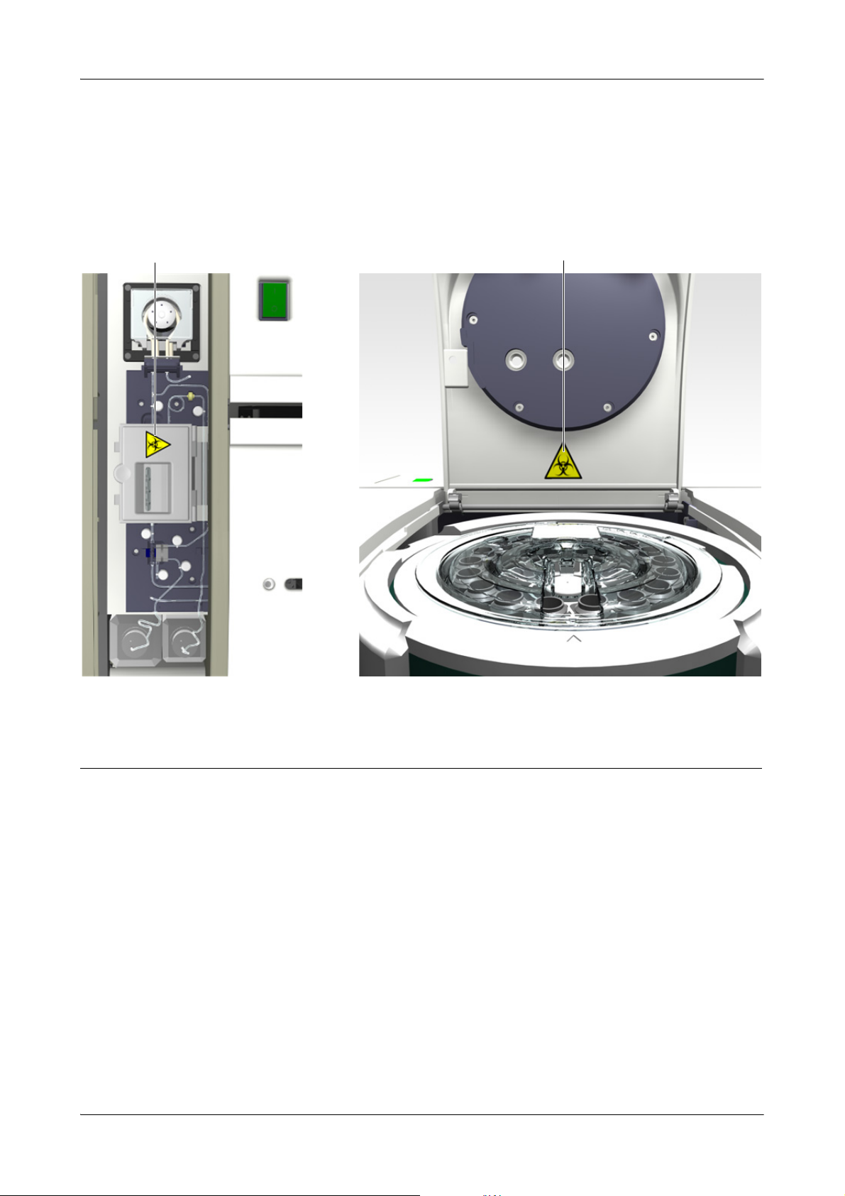
Safety labels
Read all safety labels on the instrument and equipment.
The following illustration shows where on the instrument labels are displayed.
A This label on the electrode block of the ISE unit indicates that
there is a danger of hazardous situations arising within the vicinity
of this label, which may result in death or serious injury. The relevant laboratory procedures on safe use must be observed.
(You will find this label only if an ISE unit is installed.)
Figure A-1 Safety labels on the cobasc111 instrument
In addition to safety labels on the instrument, there are safety notes in the
corresponding parts of the Operator’s Manual.
These safety notes give more detailed information about potentially hazardous
situations that may arise during daily operation or when carrying out maintenance
procedures.
When working with the instrument, be sure to observe both the safety labels on the
instrument and the safety notes in the Operator’s Manual.
B This label on the main cover indicates that there are potential bio-
hazards within the vicinity of this label, which may result in death
or serious injury.
The relevant laboratory procedures on safe use must be observed.
Roche Diagnostics
Operator’s Manual · Version 3.0 A-13
Page 24

1Safety cobas c111
Safety labels
Roche Diagnostics
A-14 Operator’s Manual · Version 3.0
Page 25

cobas c111 2 Introduction to the instrument
Table of co ntents
Introduction to the instrument
What you need to know before you start
In this chapter, you will find basic information on the features that are relevant for
working with the cobas c111 instrument.
In this chapter
Overview .................................................................................................................... A-17
Principles of operation ........................................................................................A-19
User interface .............................................................................................................A-20
Wizards ......................................................................................................................A-21
Daily operation ..........................................................................................................A-22
Overview .............................................................................................................. A-22
Reagent and diluent handling ............................................................................. A-25
Calibration ...........................................................................................................A-26
Calibration type ............................................................................................. A-27
Calibration sequence ..................................................................................... A-28
Calibration status of a set ..............................................................................A-28
Calibration result storage ..............................................................................A-28
Validating calibration results ........................................................................A-29
Calibration procedures .................................................................................. A-29
Quality control (QC) ..........................................................................................A-30
Sample handling ..................................................................................................A-31
Order handling .................................................................................................... A-32
Results ..................................................................................................................A-34
Maintenance ..............................................................................................................A-34
System status ..............................................................................................................A-35
Chapter
2
Roche Diagnostics
Operator’s Manual · Version 3.0 A-15
Page 26

2 Introduction to the instrument cobas c111
Tab l e o f c o nt en ts
Roche Diagnostics
A-16 Operator’s Manual · Version 3.0
Page 27

cobas c111 2 Introduction to the instrument
WARNING
Overview
Overview
The cobas c111 instrument is a continuous random-access analyzer intended for the
in vitro determination of clinical chemistry and electrolyte parameters in serum,
plasma, urine or whole blood (HbA1c). It is optimized for small throughput
workloads of approximately samples per day, utilizing photometric analysis and an
optional unit for ion selective electrodes (ISE).
Only trained personnel working in a professional laboratory environment may
operate the cobas c111 instrument.
Incorrect results or damage to the analyzer due to wrong operation
Operators are required to have a profound knowledge of relevant guidelines and norms as
well as the information and procedures contained in the Operator’s Manual.
o Do not carry out operation and maintenance unless you have been trained by Roche
Diagnostics.
o Carefully follow the procedures specified in the Operator’s Manual for the operation
and maintenance of the system.
o Leave maintenance that is not described in the Operator’s Manual to trained service
representatives.
o Follow standard laboratory practices, especially when working with biohazard material.
Features As part of the cobas family of instruments, the cobas c 111 instrument offers small
laboratories the following advantages:
o High analytical performance
The same bulk reagents, 12-wavelength photometer and disposable cuvettes
generate results that are highly correlated to other cobas instruments.
o Efficient operation
Cooled, exchangeable reagent disks ensure economical reagent use; disposable
cuvette segments allow for easy cuvette loading and removal.
o High reliability, low maintenance
Innovative "low impact" instrument design and software-driven preventive
maintenance improves up-time and reduces maintenance costs.
o Adaptable user interface
The built-in color touchscreen, process-driven software, and reagent and sample
barcode entry adapts to users of different skills and access levels.
o High safety standards
Built-in safety devices, such as level detection, tube bottom detection, cuvette
quality control, and ISE clot detection anticipate potential hazards during
operation.
o Flexible sampling
Eight on-board sample positions accommodate virtually any type of sample
carrier, and enable continuous sample placing and removal during operation.
o Data management
Bidirectional RS-232 and USB ports, on-board thermal printer, and drivers offer
the latest in data management capabilities.
Roche Diagnostics
Operator’s Manual · Version 3.0 A-17
Page 28
2 Introduction to the instrument cobas c111
A
L NM
B D
I
F
E
G
H
O
J
K
C
Overview
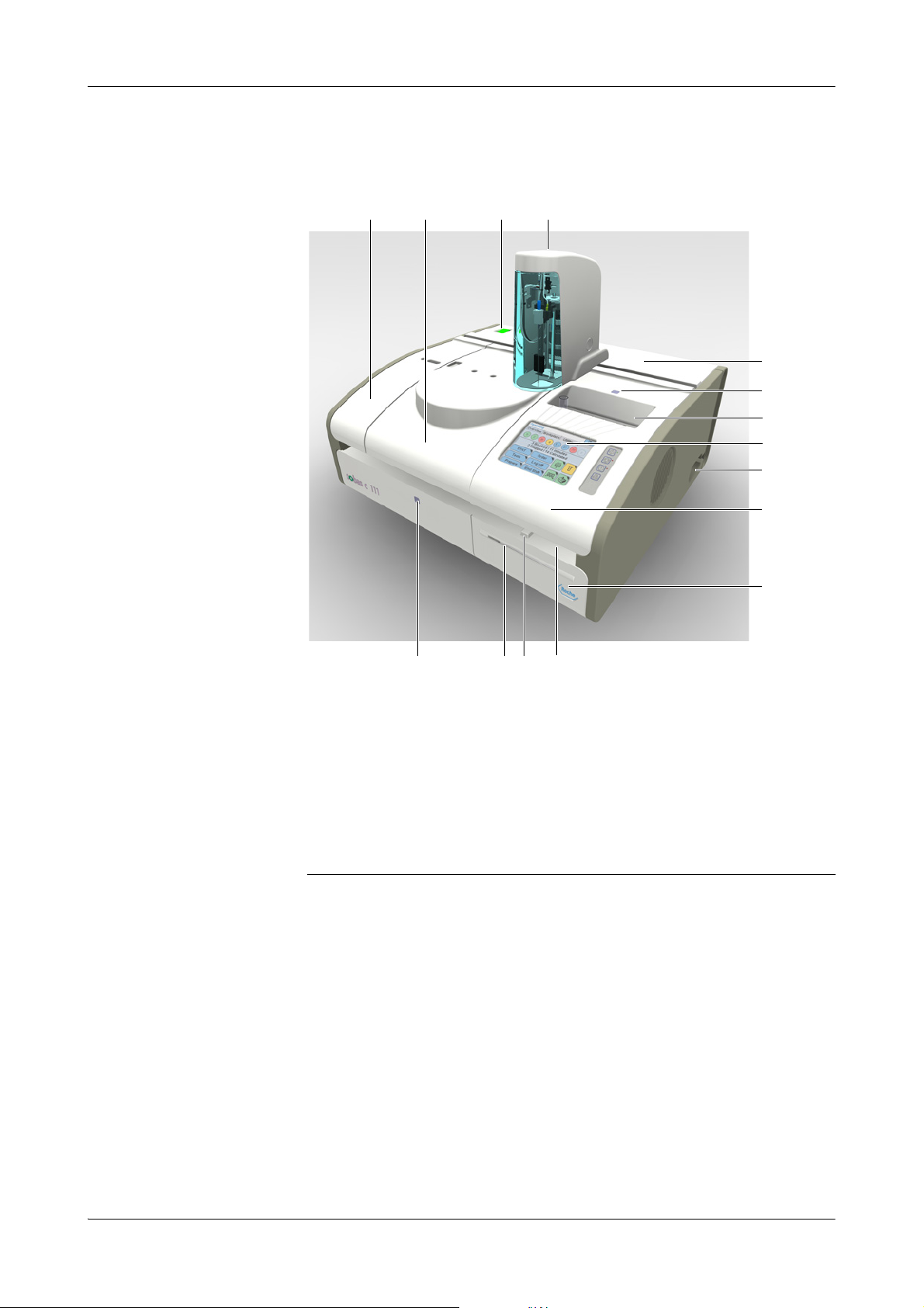
Measuring principles Measurements are performed by means of an absorbance photometer and optionally
an ISE (ion selective electrode) module that uses ion selective potentiometry.
A first look at the instrument
A Left service flap (covers wash station, ISE
tower, tubing)
B Main cover (covers rotor, reagents, cuvettes,
photometer unit)
C Main switch
D Transfer head (holds probe)
E Rear service flap (covers computer boards,
power supply, degasser)
F Sample area LED
G Sample area (space for 8 sample tubes)
Figure A-2 The cobas c 111 instrument
H Touchscreen
I Fluid connectors
J Right service flap (covers photometer unit,
sample area)
K Printer panel
L Main cover LED
M Paper slot
N Release button for printer panel
O USB connector (not shown)
Roche Diagnostics
A-18 Operator’s Manual · Version 3.0
Page 29

cobas c111 2 Introduction to the instrument
Overview
Principles of operation
The cobas c111 main instrument uses absorption photometry for determining the
amount of absorbance in a fluid. The absorbance is used to calculate the
concentration in the solution.
Loading the sample The operator identifies the sample, places it on the instrument, and defines the order.
(If you work with a host system, the order is defined automatically.)
Measuring process The measuring process for each test consists of forty regular cycles, each lasting 18
seconds. In each of these cycles, a measurement is taken, irrespective of what other
actions take place during this cycle. The application definitions determine what is
done in which cycle, and they also define which results are taken into account for the
result calculation.
With each cycle, a new test can be started.
The basic process works as follows:
1. Checking the cuvette.
A measurement is taken to check the quality of the cuvette.
2. Pipetting reagent (R1) to the cuvette.
After each pipetting action, the system performs a wash cycle to minimize carryover. During this cycle, the probe and tubing are flushed with water and cleaner.
3. Wait.
The fluid needs to reach the prescribed temperature. Such a phase can last several
cycles.
During the wait cycles, activities for other tests are performed.
4. Pipetting the next fluid.
Typically, this would be the sample. The details are defined in the application
definitions.
5. Wait.
6. Pipetting the next fluid.
7. Wait.
8. And so on.
Calculating the results The test result is calculated on the basis of the photometric measurement results.
During this process, various checks are performed to ensure that the whole measuring
process was technically correct. If values are above or below predefined limits, the test
result is flagged.
The results are stored on the system. This includes both the forty measurement results
(raw data) and the calculated test result.
Sequence of processing For a given sample, the tests are processed in the order defined by the time required
for their processing (number of cycles), starting with the one that takes the longest.
This order can be altered manually by defining a specific process sequence list.
Status of the measuring process At any stage of the measuring process, the user can check its status on the screen.
Result data management The system provides storage space for the results of one working day. For backup
purposes, the results must be exported to an external storage device once a day.
Roche Diagnostics
Operator’s Manual · Version 3.0 A-19
Page 30
2 Introduction to the instrument cobas c111
E
G
F
D
C
B
A
User interface
User interface
The cobas c111 instrument is equipped with a touchscreen, an on-screen keyboard
and four global action buttons. LEDs and acoustic signals let you know when it is safe
to add or remove samples, reagents and other fluids.
With buttons and other display items, “traffic light” color coding is used: Green
means OK, yellow: watch out, you need to do something, and red means that your
intervention is required for processing to continue.
The screens have a clear and consistent layout and are easy to use. The topics are
divided in the proven work areas: Overview for order and fluid handling, Wo rk p la ce
for result handling and details on orders, and Utilities for administration tasks.
e
For details on the user interface, see Chapter 5 Software.
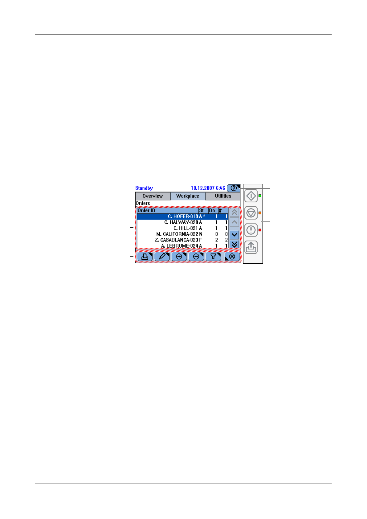
The following is an example of a screen. It contains the full range of display items.
A The status line displays the system status.
B Tab s represent the major work areas.
C The headline characterizes the content or
function of the screen. If the screen is part of
a sequence of screens (wizard), the headline
tells you where you are within this sequence.
D The working area displays the main content
of the screen.
E The buttons vary depending on the content
of the working area and the screen position
within a series of steps (wizard).
Figure A-3 Example of a screen
F The Help button leads to concise information
that is relevant to the current screen and
situation.
G The global action buttons represent the
functions that are permanently available:
Start, Stop, Alarm, Line Feed. The LEDs next
to them point to their status.
Roche Diagnostics
A-20 Operator’s Manual · Version 3.0
Page 31

cobas c111 2 Introduction to the instrument
Wizard s
Wizards
Screens help you perform your tasks. If not all steps of a task can be performed from
one screen, the workflow is realized as a sequence of screens, a so-called wizard.
cobas c 111 wizards do not usually force you to perform a task at a certain stage, they
just make your work easier.
e
For details on workflows, see Workf low s and w izar ds on page A-74.
When intervention is required On the screen, there are several methods of telling when your intervention is required:
o Buttons and texts are color coded.
Everything is fine.
To ensure smooth operation, you need to perform some task.
The current process or action has not started yet or stopped. You need to
do something for it to start or continue.
o Screens can contain instructions. For example the text may ask you to place the
sample on the sample area or to remove a reagent bottle from the reagent disk.
o Messages inform you about the status of current actions.
o A permanent alarm monitor alerts you to events you should know about.
Wizards There are three major wizards: Prepare wizard, Orders wizard, and End Shift wizard.
With most tasks that involve more than one step, such as exchanging reagent or other
fluid bottles, you are supported by wizards.
Prepare wizard The Prepare wizard guides you through the tasks that need to be performed at the
beginning of a shift. When this wizard is done, the system is ready for processing
orders.
Orders wizard The Orders wizard guides you through the process of creating and changing orders.
End Shift wizard The End Shift wizard guides you through the tasks that need to be performed at the
end of the day or to prepare the instrument for handing over to another operator.
Individual tasks can be performed outside the wizards
Most tasks that make up a workflow can be performed without using a wizard.
If you perform a task independently, you first need to navigate to the appropriate screen
and then start the task from there; whereas if you use a wizard, the appropriate screen is
displayed automatically.
Using the wizards also ensures that all necessary steps are performed and in the right
order.
Roche Diagnostics
Operator’s Manual · Version 3.0 A-21
Page 32
2 Introduction to the instrument cobas c111
Daily operation
Daily operation
Overview
Daily operation includes the routine tasks that are required to prepare and monitor
the system, and to analyze samples.
When you switch on the system, it performs several checks to make sure that all
preconditions are met, for example that all covers are closed or that there are cuvettes
available. It then performs self-tests to ensure that all modules function properly.
At the end of the startup phase, the screen is updated to display the current status of
the system.
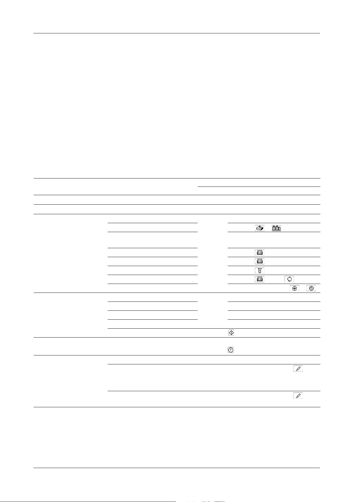
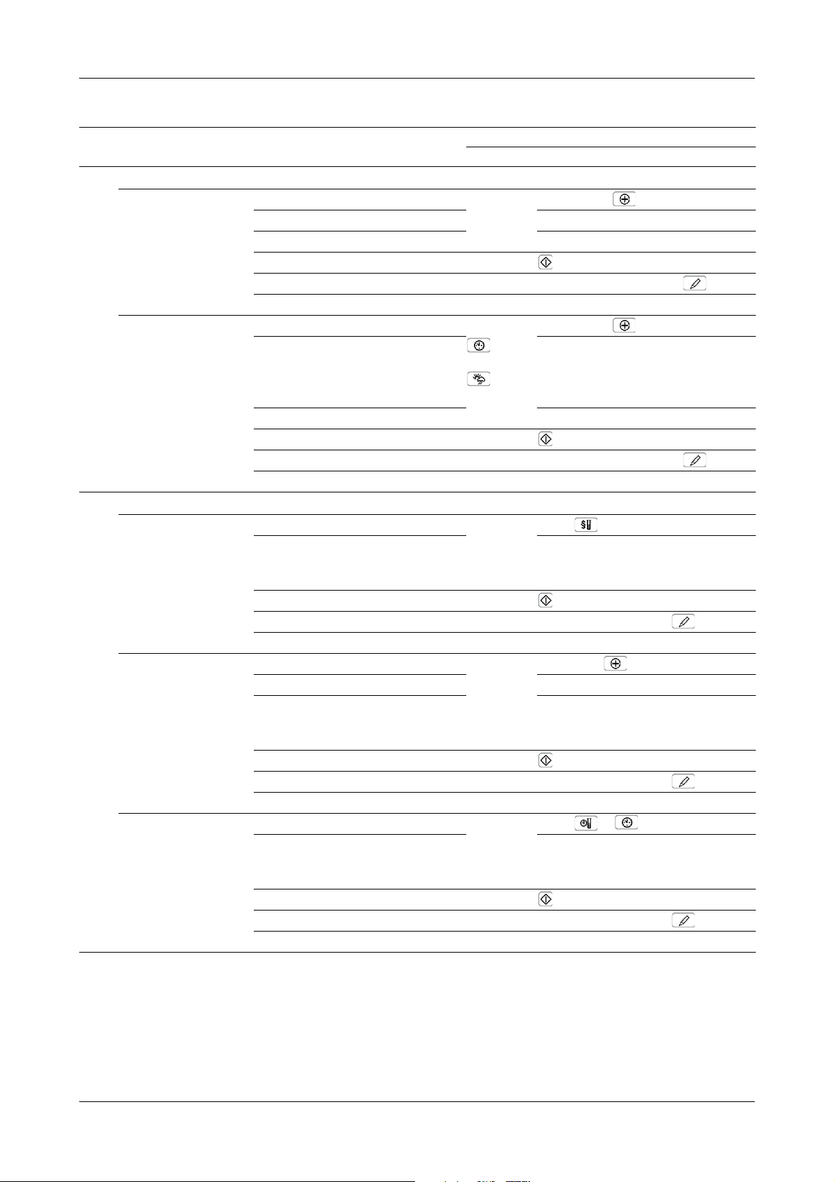
The following table gives an overview of the tasks you might need to perform during
daily operation.
Task Steps Navigation
Starting the system 1. Switch on the system.
1
Logging on the system Overview > Logon
2
Preparing the system Start the Prepare wizard. Overview > Prepare
3
Defining orders Start the Orders wizard. Overview > Order (or Overview > STAT)
4
Monitoring the progress n/a Overview
5
With wizard As individual steps
1. Check the external fluid containers. Overview > >
2. Perform the maintenance actions
that are due.
3. Load the reagent disk. Overview >
4. Check the reagents. Overview >
5. Check the cuvettes. Overview >
6. Perform mixing Overview > > test >
7. Perform calibrations that are due. Wor k pl a ce > Calibrations > >
1. Identify the sample. n/a
2. Select the tests. n/a
3. Place the sample. n/a
4. Start the run.
Utilities > Maintenance
Validating results 1. View results. n/a Wo rk p l ac e > Result Review
6
2. Handle flagged results. n/a Wo r kp l ac e > Result Review >
... > Repeat
... > Rerun
3. Accept results. n/a Wo r k pl a ce > Result Review > >
Accept
Ta b le A -1 Overview of the daily operation tasks
Roche Diagnostics
A-22 Operator’s Manual · Version 3.0
Page 33
cobas c111 2 Introduction to the instrument
Daily operation
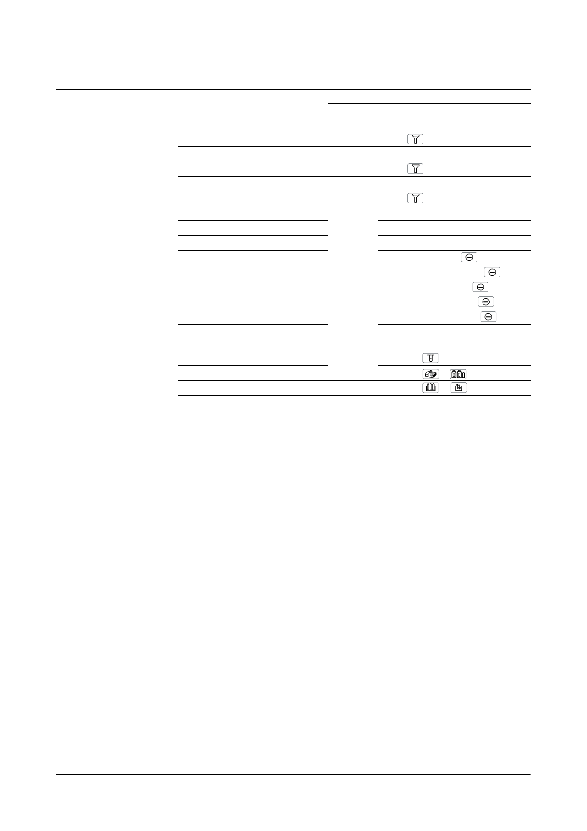
Task Steps Navigation
With wizard As individual steps
Performing calibrations
7
Performing individual
calibrations
Per form ing
all due calibrations
Performing controls
8
Per form ing
Default QC
Performing an individual
QC measurement
Performing all
due QC measurements
Ta b le A -1 Overview of the daily operation tasks
1. Start the wizard. Wo rk p l ac e > Calibrations >
2. Select the test. n/a
3. Prepare and place the calibrators. n/a
4. Start the calibration.
5. Validate the calibration results. Wo r kp l ac e > Calibrations >
6. Remove the calibrators.
1. Start the wizard. Wo rk p l ac e > Calibrations >
2. Select all tests with due calibrations.
or
Select all tests with calibration due
within the forecast period.
3. Prepare and place the calibrators. n/a
4. Start the calibration.
5. Validate the calibration results. Wo r kp l ac e > Calibrations >
6. Remove the calibrators.
1. Start the wizard. Overview > Order >
2. Select a control and place the tube.
Repeat until there are no controls left
on the screen.
3. Start the QC measurement.
4. Validate the QC results. Wo r kp l a ce > QC Status >
5. Remove the controls. n/a
1. Start the wizard. Wo rk p l ac e > QC Status >
2. Select a test. n/a
3. Select a control and place the tube.
Repeat until there are no controls left
on the screen.
4. Start the QC measurement.
5. Validate the QC results. Wo r kp l a ce > QC Status >
6. Remove the control.
1. Start the wizard. Overview > Order >
2. Select a control and place the tube.
Repeat until there are no controls left
on the screen.
3. Start the QC measurement.
4. Validate the QC results. Wo r kp l a ce > QC Status >
5. Remove the controls.
n/a
n/a
n/a
>
n/a
Roche Diagnostics
Operator’s Manual · Version 3.0 A-23
Page 34
2 Introduction to the instrument cobas c111
Daily operation
Task Steps Navigation
With wizard As individual steps
Finishing the shift 1. Check for unfinished orders. Wo rk p l ac e > Orders
9
Choose > Not Finished
2. Check for non-validated results. Wo r k pl a ce > Result Review
Choose > Not Accepted
3. Check for non-transmitted results.
(If working with a host system only.)
4. Start the End Shift wizard. Overview > End Shift
5. Perform the daily backup. Utilities > Export > Database
6. Export the full results. Utilities > Export > Results
7. Clean up the database. Wo r k pl a ce > Orders >
8. Perform the maintenance actions
that are due.
9. Replace cuvettes. Overview >
10. Check the external fluid containers. Overview > >
11. Remove the reagent disk (if last shift). Overview > >
12. Log off the system. Overview > button with your user name
13. Switch off the system (if last shift). n/a n/a
Ta b le A -1 Overview of the daily operation tasks
Wo rk p l ac e > Result Review
Choose > Not Sent to Host
Wo rk p l ac e > Result Review>
Wo rk p l ac e > QC Status >
Wo rk p l ac e > QC History >
Wo rk p l ac e > Calibrations >
Utilities > Maintenance
Roche Diagnostics
A-24 Operator’s Manual · Version 3.0
Page 35
cobas c111 2 Introduction to the instrument
A
B C
Daily operation
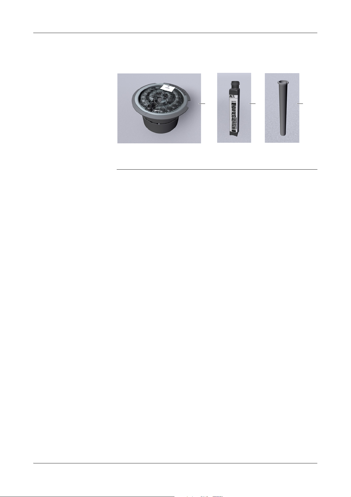
Reagent and diluent handling
A Reagent disk
B Reagent bottle with barcode
C Chimney
Figure A-4 Equipment for reagent handling
Reagent disk On the instrument, the reagents are stored on a reagent disk. It provides space for 27
bottles, allowing up to 14 reagent sets to be installed on the disk, assuming that most
tests need two reagents. Extra diluents and cleaners are also loaded on the reagent
disk.
You can work with up to eight different reagent disks on one cobas c111 instrument.
You always load and remove bottles while the disk is on the instrument. (The system
needs to know exactly what is loaded on the disk.)
When you finished running tests, you can remove the whole reagent disk, place it in a
reagent disk container, and store it in a refrigerator.
Bottles cobas c 111 reagents, diluents and extra cleaners are provided in uniform bottles. They
are supplied with two dimensional barcodes and placed on the reagent disk with their
cap removed.
Chimneys Chimneys are bottle inserts that reduce evaporation. For reagents that are especially
sensitive to concentration changes, Roche recommend using chimneys on the reagent
bottles. (See the package inserts of the tests whether you should use chimneys or not.)
To generally reduce evaporation, you may use chimneys on all reagent bottles.
Reagent set Up to three reagents can be required to perform a certain test. These reagents are
handled in reagent sets. You can define more than one reagent set for a test, but only
one can be active.
A reagent set is defined as soon as its first bottle is loaded. From this moment on,
whenever you remove or replace a reagent, you do so for all reagents of the set.
Each diluent or cleaner bottle is treated as a separate reagent set.
Roche Diagnostics
Operator’s Manual · Version 3.0 A-25
Page 36
2 Introduction to the instrument cobas c111
Daily operation
Volum e d et ec t io n For each reagent set, the number of available tests is continuously calculated.
Figure A-5 Remaining tests indication
Periodic mixing Reagents may have a mixing interval defined. This interval is checked by the system
every 30 minutes, and mixing is performed without removing the reagent bottles
from the reagent disk.
For a reagent set that contains more than one reagent for which mixing is defined, the
shortest interval of all reagents of the set is used for all reagents.
Calibration
Tests are blocked if any reagent they use requires mixing.
Diluents Both, system water and dedicated diluents are used. System water is kept in the
external water container, dedicated diluents are supplied in reagent bottles and placed
on the reagent disk.
Cleaners Both, a system cleaner and dedicated cleaners can be used. The system cleaner is kept
in the external cleaner bottle, dedicated cleaners are supplied in reagent bottles and
placed on the reagent disk.
Calibration is the process that establishes, under specified conditions, the relationship
between values indicated by the analytical instrument and the corresponding known
values of an analyte.
Periodic calibration is required because the concentration of reagents can change over
time.
Reagents are typically calibrated with a two-point calibration, measuring the
predefined value of a multicalibrator and of system water. Some reagents are
calibrated using a set of calibrators.
On the cobas c111 instrument, reagents are handled as sets of up to three reagents.
(You always load and unload all reagents of a set.) As a consequence, all reagents
(bottles) of a set are calibrated when performing calibration.
The system checks when calibration is due.
Each reagent set must have accepted calibration results to be available for use in tests.
When a calibration is due depends mainly on two definitions, the calibration type and
the calibration sequence.
Roche Diagnostics
A-26 Operator’s Manual · Version 3.0
Page 37
cobas c111 2 Introduction to the instrument
Daily operation
Calibration type
The calibration types Set and Lot define the manner in which the system determines
whether there is a valid calibration result for a particular reagent set.
Set calibration Set calibration results are valid for the calibrated set only. They can be generated from
any reagent set.
Lot calibration Lot calibration results are valid for the reagent set they were calibrated with and for all
subsequent reagent sets of the same lot. Usually, lot calibrations are generated by
calibrating the first reagent set of a new lot. There can only be one accepted lot
calibration result for the reagents of a given lot.
Let us suppose that you place the first reagent set of a new lot and calibrate it straight
away. Let us further assume that subsequent control measurements suggest that a new
calibration is required. Within the first 24 hours of placing a set on the system, you
can recalibrate it, and possibly existing lot calibration results of this set are
superseded. When this period has elapsed you can no longer change the lot
calibration results. (To generate new lot calibration results, you would have to delete
the existing results and then calibrate a new reagent set.)
Lot calibration is relevant if you work with the calibration sequence [Each Lot and Interval].
The following table illustrates the two calibration types in an example.
Assumptions:
o Sequence: Each Lot and Interval.
o Interval: 5 days.
(Note that the interval (re)starts when a set is calibrated as a result of the interval
expiring or a new lot being started.)
Day Trigger/Event Task Result used Set Cal. type Cal. Usage
1 NA 1. Place first reagent set of new lot.
2. Calibrate set L1/1.
2 Reagent empty. 1. Remove set L1/1.
2. Place new set L1/2.
Reagent empty. Replace set whenever it is empty. Result 1 Set Current
5 Interval expired. Calibrate current set L1/n. Result 2 L1/n
6 Reagent empty. Place new set L1/n+1. Result 1 L1/n+1
8 Reagent empty.
New lot.
Reagent empty. Place new set L2/2. Result 3 L2/2
10 Interval expired. Calibrate current set L2/n. Result 4 L2/n
11 Reagent empty. Place new set L2/n+1. Result 3 L2/n+1
Ta b le A -2 Example for set change and calibration types
1. Remove set L1/n+1.
2. Place new set, which is the first set of a new lot.
3. Calibrate set L2/1.
Result 1 L1/1 Lot Current
Result 1 L1/2
L1/1
L1/n-1
L1/n
Result 3 L2/1
L1/1
L1/n+1
L2/1
L2/n-1
L2/n
Set
Lot
Set
Set
Set
Set
Lot
Lot
Set
Set
Lot
Set
Set
Set
Set
Current
-
Current
Obsolete
Current
Obsolete
Current
Obsolete
Obsolete
Current
-
Current
Obsolete
Current
Obsolete
Roche Diagnostics
Operator’s Manual · Version 3.0 A-27
Page 38

2 Introduction to the instrument cobas c111
Daily operation
Calibration sequence
The calibration sequence is an application definition. It defines the manner in which
the system determines when a calibration is due.
Roche recommend not to change the calibration sequence.
The calibration interval defines the on-board stability of a reagent.
One of the following sequences applies to each reagent set:
No Interval You perform calibration whenever you think fit. Use this value if you are sure that the
reagent is stable until it is empty and you replace it with a new one. Calibration is due
whenever a new reagent set is loaded on the instrument.
Interval Only You perform calibration only when the interval has expired.
Each Lot and Interval You perform calibration whenever the fist reagent of a new lot is loaded and then each
time the interval has expired.
In this case, the interval is related to the date when the lot calibration was generated,
and it (re)starts whenever you calibrate a reagent set (as a result of interval expiry or
starting a new lot).
Each Set and Interval You perform calibration whenever a new reagent is loaded and when the interval has
Calibration status of a set
You can turn off the interval check by defining its duration as 0 (zero).
expired.
The interval starts again whenever you calibrate a reagent set because the interval had
expired or a new lot was started.
You can turn off the interval check by defining its duration as 0 (zero).
Each reagent set has one of the following calibration statuses:
CU (current) denotes that the set is on board and that its calibration results are currently
used.
OB (obsolete) denotes that the set’s calibration results are no longer used.
This status applies for example to the following situations:
o The set was removed and it is empty.
o The set was removed and it is not empty. It was removed more than 30 days ago.
SB (standby) indicates that the set’s calibration results are not currently used.
This status applies for example to the following situations:
o A new set was loaded and calibrated while an identical set was still in use (pre-
calibration).
o The set was removed not more than 30 days ago and it is not empty.
Calibration result storage
The current and up to five obsolete calibration results are stored on the system. If
there are more than five obsolete calibration results, the oldest obsolete calibration
results are automatically deleted as part of the daily end of shift activities.
Roche Diagnostics
A-28 Operator’s Manual · Version 3.0
Page 39

cobas c111 2 Introduction to the instrument
<xyz>
Daily operation
Validating calibration results
Applications define checks for ranges and limits. If these are exceeded, the results are
flagged.
Each new calibration result has to be validated. If flags were generated, you must
determine their cause and decide whether to accept the result, rerun the calibration or
continue using the old calibration results.
You can automatically accept unflagged results and results with flags that are
contained in a specific list of flags that should be ignored.
e
See Editing the acceptable flags list on page B-162.
Calibration procedures
There are three basic procedures for performing calibration:
o Calibrating all reagent sets that need calibrating
o Calibrating all reagent sets that will need calibrating during the forecast period
o Calibrating individual reagent sets
Forecast per iod The forecast period is a configurable period of time. Calibrations that fall due within
this period will be performed collectively.
e
See Calibration on page B-167.
Typically you would set this period to fit your shift length, for example 8 hours. This
would enable you to prepare the instrument before the work shift starts and so avoid
having to interrupt sample processing for performing calibrations.
Precalibration At any given time, there is only one accepted calibration result for each test. You can,
however, install and precalibrate one reserve reagent set. This is done, for example, to
ensure continuous sample processing.
Roche Diagnostics
Operator’s Manual · Version 3.0 A-29
Page 40

2 Introduction to the instrument cobas c111
Daily operation
Quality control (QC)
QC is performed at regular intervals to check the integrity of the whole measuring
system. For each test, up to three controls are defined. The results are compared
against predefined ranges or values and then interpreted accordingly.
Control A control is a sample that has been measured using all tests it is associated with, in
order to define the ranges and values that determine the correct functioning of the
instrument. This is typically done both for the normal and the pathological analyte
concentration.
When QC is due With regards to when it needs to be performed, QC is divided in the following types:
o QC After Cal
The QC measurement is due after calibration of the test.
o Interval QC
QC is due whenever its interval has expired. QC measurements of this type are
performed in a batch, typically once or twice a day.
o Default QC
QC is performed at certain times during routine operation. This is done to fit in
with laboratory processes and procedures.
Ways of performing QC With regards to how QC is performed, the following methods are provided:
o Default QC
Default QC is an automated process for performing multiple QC measurements
at the time when you define the QC orders. This is the ideal method if you want to
perform QC at certain times and days.
This method only applies to tests whose controls are defined to be performed as
part of Default QC. Therefore, if you intend to work with the Default QC
function, you need to configure the tests accordingly.
Default QC follows a streamlined procedure where the necessary QC orders are
automatically defined as soon as you identify a control. An order is defined for
each test for which this control is defined, provided the test is currently active on
the system. A wizard helps you select the controls, and a placement list supports
you in preparing and loading the controls.
o Interval QC
This method applies to tests whose controls have an interval defined.
Interval QC is a process that is suitable both for performing a single QC
measurement and for performing all QC measurements that are due. You can
select all tests that require QC simply by pressing a button. (This selection also
reflects QC of the type QC After Cal.) A wizard helps you select the controls, and
a placement list supports you in preparing and loading them.
Roche Diagnostics
A-30 Operator’s Manual · Version 3.0
Page 41
cobas c111 2 Introduction to the instrument
A
WARNING
Daily operation
Validating QC results Each new QC result has to be validated. If flags were generated, you must determine
their cause and decide whether to accept or ignore the result.
You can automatically accept unflagged results and results with flags that are
contained in a specific list of flags that should be ignored.
e
See Editing the acceptable flags list on page B-162.
If you ignore a QC result you exclude the result from further QC result calculations
such as QC History statistics.
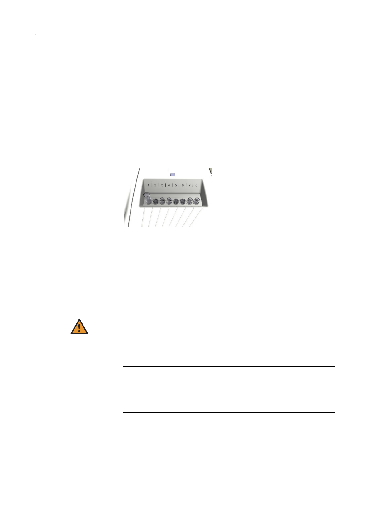
Sample handling
You can place up to eight sample tubes on the sample area.
A Sample area LED. A green LED indicates that you should place a tube, a blinking yellow LED
that you should keep clear of the sample area.
Figure A-6 Sample area with sample tubes
Sample types The cobas c111 instrument can process the following sample fluids:
o Serum
o Plasma
o Urine
o Whole blood for HbA1c
Incorrect results due to inadequate sample preparation
Specimen containing clots may obstruct the probe. Specimen containing bubbles or foam
may cause level detection errors and air pipetting. Consequently, incorrect results may be
generated.
Take adequate care when preparing the samples.
Incorrect results due to insufficient fluid
Insufficient fluid may lead to inaccurate pipetting and consequently to incorrect results.
Always fill the tubes with enough fluid that at least the defined dead volume of fluid is left
when pipetting is complete.
e
See Tubes on page A-54.
Roche Diagnostics
Operator’s Manual · Version 3.0 A-31
Page 42

2 Introduction to the instrument cobas c111
NOTICE
Daily operation
Sample tubes The cobas c111 instrument can use both primary and secondary tubes (cups).
You can use any type of primary tube, as long as their dimensions lay within
prescribed limits. Roche recommend using approved cups only.
e
See Tubes on page A-54.
Probe damage due to not removing primary tube caps
The probe is not designed to pierce tube caps. It can get damaged when trying to pierce
tube caps.
Always remove the caps of primary tubes before placing them on the instrument.
Sample ID The sample ID is an identifier of up to 23 alphanumeric characters that is unique
within a whole organization, for example the hospital. It identifies the sample and is
also used for host communication.
Sample IDs are defined either by scanning a barcode or by typing them manually.
Because there is limited space when displaying lists on screens, Roche recommend to
limit the ID to 13 characters.
Sample barcode You can use sample tubes with or without barcode.
Removing sample tubes You can remove sample tubes as soon as pipetting is complete.
Order handling
Order Mode The order mode reflects the way in which you organize the tests on the test selection
Dilution Pre-dilution is used when performing calibration.
Post-dilution is used when measuring samples.
(The dilution factor is part of the application definition and therefore does not need
to be defined by the operator.)
screen.
Choose Easy if the reagents fit on one or two reagent disks and you work with one test
panel on the screen (You can fit up to 25 tests and profiles on this panel).
Choose Full if you distribute the reagents across several (up to eight) reagent disks
and if you predominantly work with specific groups of tests, for example for
emergency situations or for testing diabetes. You can assign up to 20 tests and profiles
to each panel (tab).
Order ID The order ID is an identifier of up to 23 alphanumeric characters that is unique
within the laboratory. The order ID identifies the order and links it to the sample.
Order and sample IDs are often identical. Using separate IDs makes sense when
working with a host system.
Order IDs are defined either by scanning a barcode or by typing them manually.
Because there is limited space when displaying lists on screens, Roche recommend to
limit the ID to 13 characters.
Patient demographics The cobas c111 software does not support the handling of patient demographic data.
Roche Diagnostics
A-32 Operator’s Manual · Version 3.0
Page 43

cobas c111 2 Introduction to the instrument
Daily operation
Host connectivity The cobas c111 instrument can be connected to an external laboratory information
system (LIS), a host computer for downloading order information and uploading
results, or a cobas c 111 Printer Tool.
If the instrument is connected to a host system, the following setups can be
configured:
o Downloading order information
When you identify a sample using the barcode scanner, the appropriate order
information is automatically assigned to the order on the system. (The order
information was downloaded previously.)
o Performing host queries
When you identify a sample using the barcode scanner, a query is sent to the host,
asking for the order information of the sample in question. This information is
then downloaded to the cobas c111 instrument and automatically assigned to the
sample on the system.
o Transmitting results
You can have results automatically transmitted to the host as soon as they are
accepted.
e
For the setup when connecting to a cobas c111 Printer Tool, see the cobas c111 Printer
Tool Operator’s Manual.
Routine orders Routine orders are normally defined on the Overview tab. The software guides you
through the process of assigning the tests to the sample and placing the sample tube
on the instrument.
STAT orders STAT (short turn around time) orders are handled in the same way as routine orders,
except that their tests are processed next, irrespective of the scheduling of routine
order tests.
Defining orders There must be at least one free sample tube position when defining an order. You are
guided by the software when ordering the tests and placing the samples.
There can be only one order for each test and sample.
Modifying orders The process for changing an order is similar to that of defining it. You first identify the
sample and then change the tests. You can change an order as long as its processing
has not yet started.
It is always possible to add a further test to an existing order.
Deleting orders At the end of a shift, you should delete all orders that are defined on the system. This
is to free storage space for the next shift. Deleting the orders is an integral part of the
End Shift wizard. (Deleting an order also deletes the corresponding sample results.)
You can export the data to a USB stick and store them on a computer.
Controlling the run Controlling the execution of test runs is done via the global action buttons.
Press to start the run.
Press to stop the run.
Roche Diagnostics
Operator’s Manual · Version 3.0 A-33
Page 44

2 Introduction to the instrument cobas c111
Maintenance
Results
You can check the results on the screen as soon as they are calculated.
Units Results are normally given in your lab units. The units can be configured.
Flags Result flags are test-specific. They indicate that the limit of an internal check was
exceeded or not reached.
System flags point to the status of the result within the process of analysis; for
example, they tell you that the result has not been accepted or that is has not been
transmitted to the host successfully.
Printing results You can print all or selected results on the built-in printer.
Val idating results All results need to be validated (result accepted, test rerun or repeated).
Result flags help you identify critical results and point to possible actions that need to
be taken.
Each test must have accepted calibration results; tests whose associated calibration
results are not accepted cannot be performed.
Ratio results The user can manually define ratios. Ratio results are handled like any other sample
result, with the exception that they cannot be accepted by the user. They are
automatically accepted if all their constituent results are accepted.
Repeating and rerunning tests If a result is flagged, you may decide to run a test again. You can either perform
exactly the same test (Repeat) or perform it with a different predefined dilution
(Rerun).
Storing results The cobas c111 instrument is designed to hold the sample results of one day’s
analyzing. Therefore, you need to back up the data regularly to an external medium.
(Backing up results is an integral part of the End Shift wizard.)
The QC results of the previous and the current months are stored on the system.
Up to five calibration results are stored on the system for each test.
Maintenance
Completing maintenance actions correctly and on time helps to ensure smooth and
uninterrupted operation of your instrument.
Maintenance scheduling The cobas c111 instrument facilitates performing the maintenance actions in bundles
at the times that suit your laboratory work processes. To that purpose, you can define
in the configuration settings one day of the week as your maintenance day.
e
For information on scheduling maintenance actions, see Scheduling maintenance actions
on page B-158.
All maintenance actions can be performed any time.
Roche Diagnostics
A-34 Operator’s Manual · Version 3.0
Page 45

cobas c111 2 Introduction to the instrument
System status
Interval For most maintenance actions a fixed maintenance interval is defined. (You cannot
change this interval.) This is the basis upon which the system calculates the date when
the actions need to be performed.
The interval timers and counters are reset whenever you confirm that the
maintenance action has been performed.
Maintenance actions without predefined intervals are performed whenever necessary,
or they are triggered by another maintenance action.
Due date The due date is the last possible maintenance day. This is the date you see when you
check the status of maintenance actions.
Ensuring smooth operation Performing all due maintenance actions during the daily Prepare or End Shift phase
ensures that routine operation does not have to be interrupted for performing
maintenance actions.
System status
The cobas c111 instrument provides several means of indicating the status of the
various parts and processes:
o Color coded LEDs on the instrument inform you when and when not to open
covers or place sample tubes.
e
See Color interpretation for LEDs on page A-122.
o The colors of buttons inform you whether you need to intervene.
e
See Color concept on page A-74.
You can check the meaning of a button using the online Help .
o Buttons on the Overview tab lead to detailed information on the status of selected
processes and hardware items.
o Messages on the screen provide information on individual tasks and events.
o The text in the Status line provides information on the status and activities of the
analyzer and photometer unit.
The following system statuses are defined:
Status Comment
Standby The user and host interfaces remain active, as do the reagent
Maintenance A maintenance action is being performed. The system is not
Diagnostics A diagnostics action is being performed. The system is not
Operating Processing is in progress.
Pow er up After switching on, the system performs initialization and
Pow erdo wn Regular shutdown is in progress.
E-Stopped Processing has stopped. User intervention is required to allow
Ta b le A- 3 System statuses
cooling system, fluid system, and the cuvette heating.
available for performing tests.
available for performing tests.
functional test.
the system to resume regular operation.
Roche Diagnostics
Operator’s Manual · Version 3.0 A-35
Page 46

2 Introduction to the instrument cobas c111
System status
Roche Diagnostics
A-36 Operator’s Manual · Version 3.0
Page 47

cobas c111 3Hardware
Table of co ntents
Hardware
The parts and how they work
In this chapter, you will find information on the main hardware components of the
cobas c 111 instrument.
In this chapter
Covers and panels ......................................................................................................A-39
LEDs ...........................................................................................................................A-41
Main components .....................................................................................................A-43
Hardware overview ...................................................................................................A-44
Sample area ..........................................................................................................A-44
Fluid system .........................................................................................................A-45
Probe and syringe .......................................................................................... A-46
Syringe assembly ............................................................................................ A-46
Wash station ................................................................................................... A-47
External fluid connectors ..............................................................................A-47
Transfer unit ........................................................................................................ A-48
Fluid containers ................................................................................................... A-50
Waste containers ............................................................................................A-50
Water container .............................................................................................A-51
Cleaner bottle ................................................................................................ A-52
Reagent bottles ...............................................................................................A-53
Tubes ..............................................................................................................A-54
Cuvettes ..........................................................................................................A-55
Cuvette segments ...........................................................................................A-55
Handling cuvettes .......................................................................................... A-56
Reagent handling ...........................................................................................A-56
Rotor ....................................................................................................................A-57
Reagent disk .........................................................................................................A-58
Reagent disk container ........................................................................................ A-59
Reagent cooler ..................................................................................................... A-59
Cuvette ring .........................................................................................................A-60
Barcode scanner ...................................................................................................A-61
Printer ..................................................................................................................A-62
Chapter
3
Roche Diagnostics
Operator’s Manual · Version 3.0 A-37
Page 48

3 Hardware cobas c111
Tab l e o f c o nt en ts
Absorbance photometer ......................................................................................A-63
Connectors ...........................................................................................................A-64
Fuses .....................................................................................................................A-65
Technical specifications .............................................................................................A-66
Roche Diagnostics
A-38 Operator’s Manual · Version 3.0
Page 49
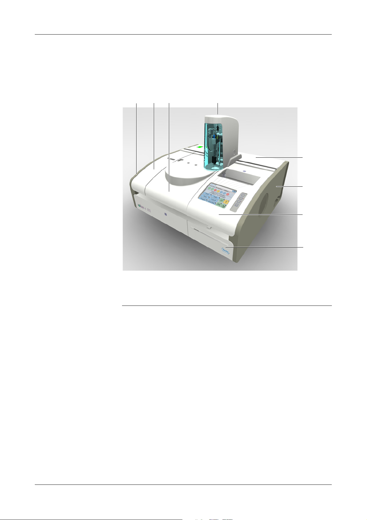
cobas c111 3Hardware
B C D
F
E
G
A
H
Covers and panels
Covers and panels
The following figure shows the removable panels and the lids that can be opened.
A Left side panel
B Left service flap
C Main cover
D Transfer head cover
Figure A-7 The cobas c 111 instrument
Transfer head cover Provides access to:
o Trans f e r mechanism
o Probe
Switch off the system before you open this cover.
Left service flap Provides access to:
o Wash station
o Tu b in g
o Internal waste tank
o Initialization plate
Open this flap as instructed during maintenance actions, or switch off the system
before you remove it.
To open the flap, press its front towards the instrument and lift.
E Rear service flap
F Right side panel
G Right service flap
H Printer panel
Roche Diagnostics
Operator’s Manual · Version 3.0 A-39
Page 50

3 Hardware cobas c111
Covers and panels
Main cover Provides access to:
o Rotor
o Reagent disk
o Cuvettes
o Reagent bottles
o Photometer unit
You open this cover whenever you need to handle cuvettes, reagent bottles, or the
reagent disk. A green LED indicates that you should place an item, a yellow LED that
you should not open the main cover.
To open the cover, press the release button at the underside of the front of the cover.
When you should close the cover an acoustic signal is sounded and the
on the System Status screen
Rear service flap Provides access to:
o Computer boards
o Power supply
o Trans f e r un it
o Degasser
This flap should be opened by service representatives only.
Switch off the system before you open this cover and remove the two side panels
before opening this flap.
Right side panel Provides access to:
o Syringe assembly
Remove this panel as instructed during maintenance actions or switch off the system
before you remove it.
Right service flap Provides access to:
o Photometer unit
o Sample area
o To u c h s c r e e n
o Data management computer
system icon
turns red.
Open this panel as instructed during maintenance actions or switch off the system
before you open it.
Printer panel Provides access to:
o Printer paper.
You can open this flap any time as long as the printer is not printing.
To open the panel, press the release button.
Roche Diagnostics
A-40 Operator’s Manual · Version 3.0
Page 51
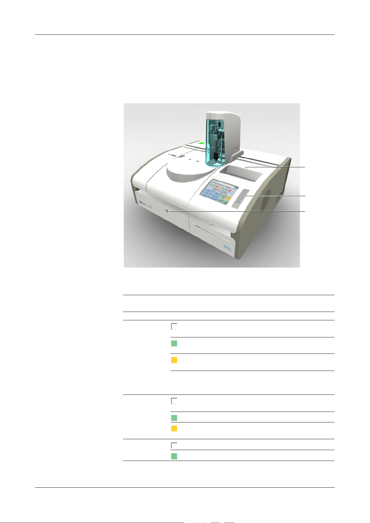
cobas c111 3Hardware
B
A
C
LEDs
LEDs
LEDs are placed on key positions on the cobas c 111 instrument. They inform you
whether you can perform certain actions.
Interpreting the LED colors
A Sample area LED
B Global button LEDs (from top: Start LED,
Stop LED, Alarm LED)
Figure A-8 The cobas c 111 instrument
LED Color Meaning
Main cover LED
Sample area LED
Start LED
Off No activities in this area. You can open the main
An acoustic signal is sounded when the cover is open while the system is
in Operating state. You can adjust the volume (Utilities >
Configuration > System > Vo l u m e ).
Off No activities in this area. You can remove sample
Blinking The transfer head is approaching. Do not place
Off You cannot start the measuring process.
C Main cover LED
cover.
User intervention is required, for example you are
expected to place or remove a bottle.
The system is performing some action. Do not
handle the cover.
tubes.
You are expected to place a sample tube.
your hand or any object in the sample area.
You can start the measuring process.
Ta b l e A - 4 LEDs and their meaning
Roche Diagnostics
Operator’s Manual · Version 3.0 A-41
Page 52

3 Hardware cobas c111
LEDs
LED Color Meaning
Stop LED
Alarm LED
Ta b l e A - 4 LEDs and their meaning
Off Pressing does not have any effect.
Pressing leads to the various stop options.
Off There are no unconfirmed alarm messages.
There is at least one unconfirmed alarm message.
You need to deal with it as soon as possible.
There is at least one unconfirmed alarm message.
You need to deal with it immediately, processing
may not be able to continue unless you do so.
An acoustic signal is sounded when an alarm is generated. You can
adjust the volume (Utilities > Configuration > System > Vo l u m e ).
Roche Diagnostics
A-42 Operator’s Manual · Version 3.0
Page 53

cobas c111 3Hardware
J
K
A B C D E
F
I
G
H
Main components
Main components
The following figure illustrates the main components of the cobas c111 instrument.
A Rotor
B Transfer unit
C Photometer unit
D PCB main board
Figure A-9 Main hardware components
Rotor Provides a cooled area for reagents (cooling assembly) and a heated channel for
Transf e r un it Pipettes sample, reagent, and other fluids from their source to target containers such
Photometer unit Contains the absorbance photometer used for making absorbance measurements.
PCB main board Controls the instrument hardware.
E Degasser
F Sample area
G Display
H Syringe assembly
cuvettes. It moves the containers to the correct position for loading, removal,
pipetting, and measuring.
as cuvettes or the wash station.
I Front USB port
J External fluid rack
K Printer
Roche Diagnostics
Operator’s Manual · Version 3.0 A-43
Page 54
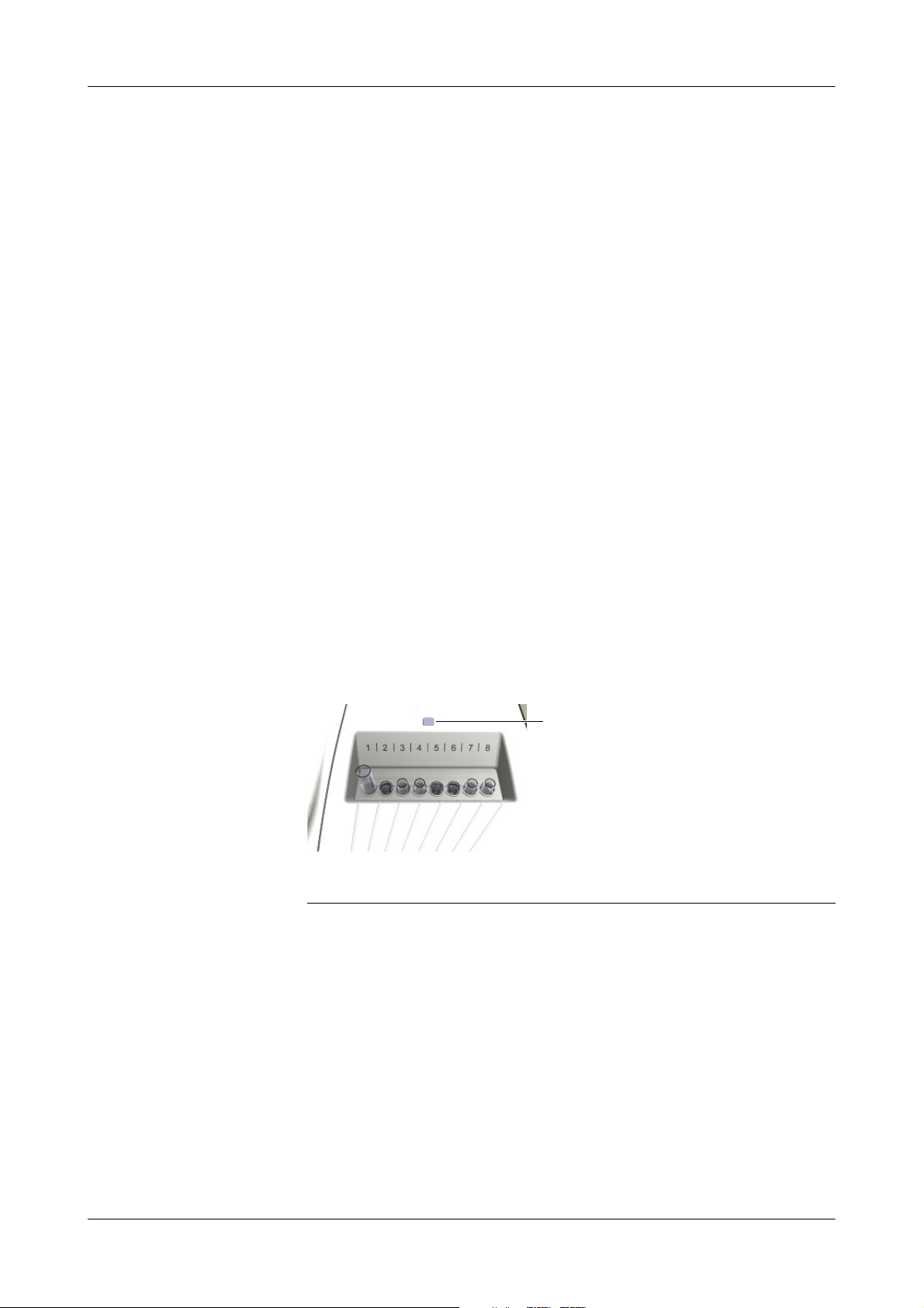
3 Hardware cobas c111
A
Hardware overview
Fluid system (not shown) Transports all fluids around the instrument, including sample, reagent, calibrator,
control, diluent, cleaner, system water, and waste.
Syringe assembly Performs the aspiration and dispensing of fluids. This includes the supply of water
and cleaner to clean the probes in the wash station after every pipetting action, which
prevents carry-over between tests.
Degasser Removes possible air bubbles from the system water.
Sample area Eight positions for holding sample tubes. This area is also used for placing calibrators,
controls, and auxiliary fluids.
Display The touchscreen provides the user interface for controlling and managing the
cobas c 111 instrument.
Front USB port This port is used for the USB stick when backing up data or loading data on the
system.
Hardware overview
Sample area
The sample area provides eight positions for placing sample tubes. You can place
primary and secondary tubes.
e
See Tubes on page A-54.
A The LED indicates that the transfer tower is approaching or that you should place a sample
tube.
Figure A-10 Sample area with sample tubes
Place the samples when instructed by the system to do so. For calibrators, the system
tells you on which position to place them, with the other fluids, you can choose any
free position.
Roche Diagnostics
A-44 Operator’s Manual · Version 3.0
Page 55
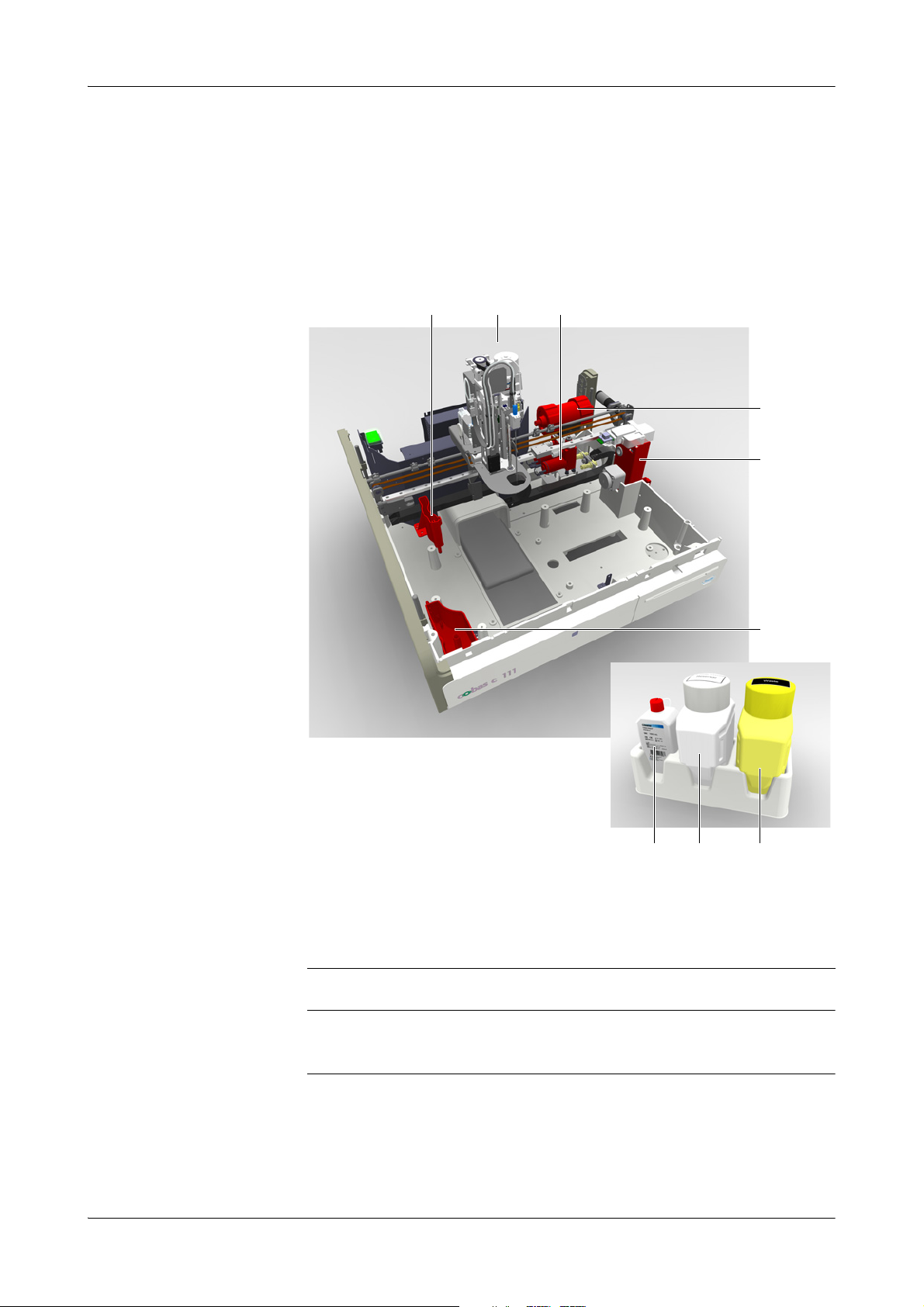
cobas c111 3Hardware
A
D
C
E
IHG
F
B
NOTICE
Hardware overview
Fluid system
The fluid system consists of all the valves, pumps, tubing, syringe, fluid sensors, water
and waste containers, the wash station, and the probe. It transports all fluids around
the instrument, including sample, reagent, calibrator, control, diluent, cleaner, system
water, and waste. The fluid system also delivers the correct amounts of fluids to the
cuvettes.
A Wash station
B Transfer head (with probe)
C Pumps
D Degasser
E Syringe assembly
Figure A-11 Fluid system
To prevent overflow of the internal waste tank when the system is in Standby status, the
waste is periodically pumped to the external waste container. (Condensation can build up
in the cooling assembly while the system is in Standby status.)
F Internal waste tank
G Cleaner bottle (red cap)
H Water container (white)
I Waste container (yellow)
Roche Diagnostics
Operator’s Manual · Version 3.0 A-45
Page 56
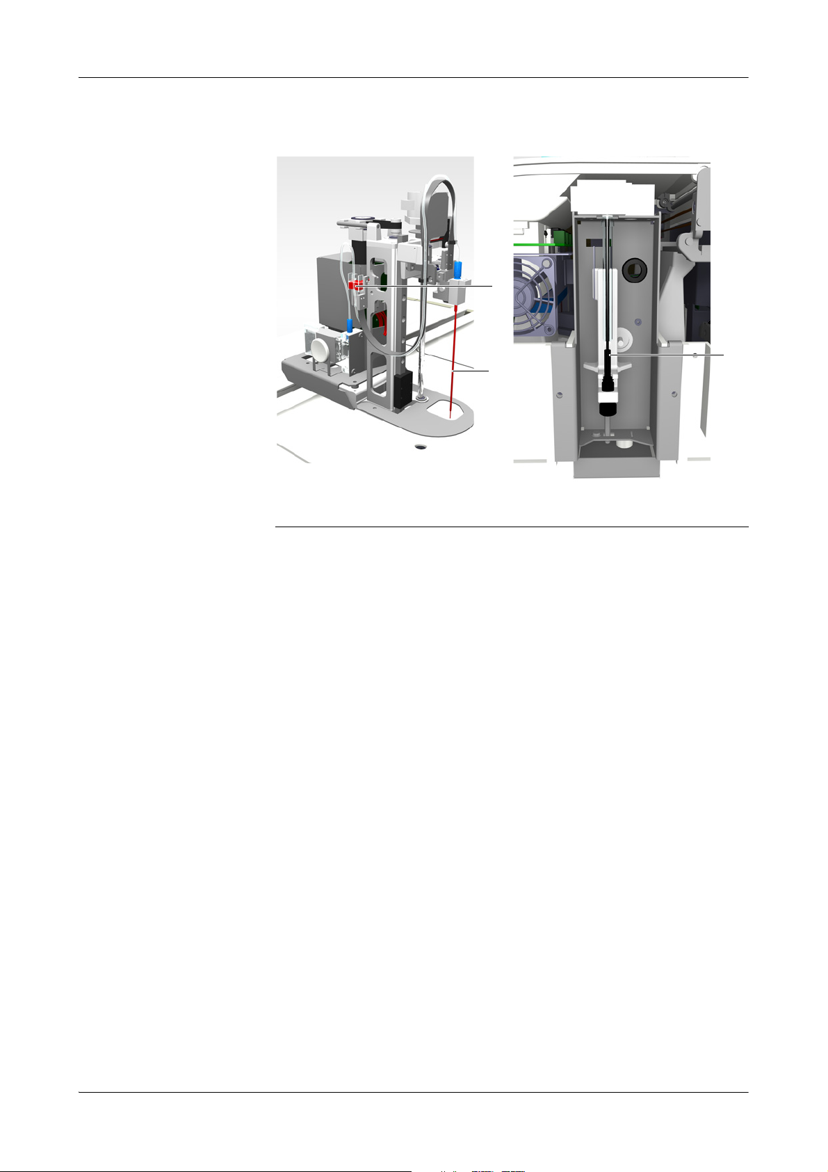
3 Hardware cobas c111
B
A
C
Hardware overview
Probe and syringe
Syringe assembly
A Fluid sensor
B Probe
Figure A-12 Probe and syringe
The probe is connected by tubing to:
o The syringe to ensure the pipetting of the required amounts of fluid.
o The external water container and cleaner bottle to ensure supply of fresh water
and cleaner.
e
See maintenance action Clean the probe manually on page C-12.
See maintenance action Deproteinize the probe on page C-10.
See Replacing the probe on page B-125.
The syringe assembly controls the aspiration and dispensing of fluids. It also controls
the supply of water and cleaner to clean the probes in the wash station after every
pipetting action, which prevents carry-over between tests.
C Syringe
Roche Diagnostics
A-46 Operator’s Manual · Version 3.0
Page 57
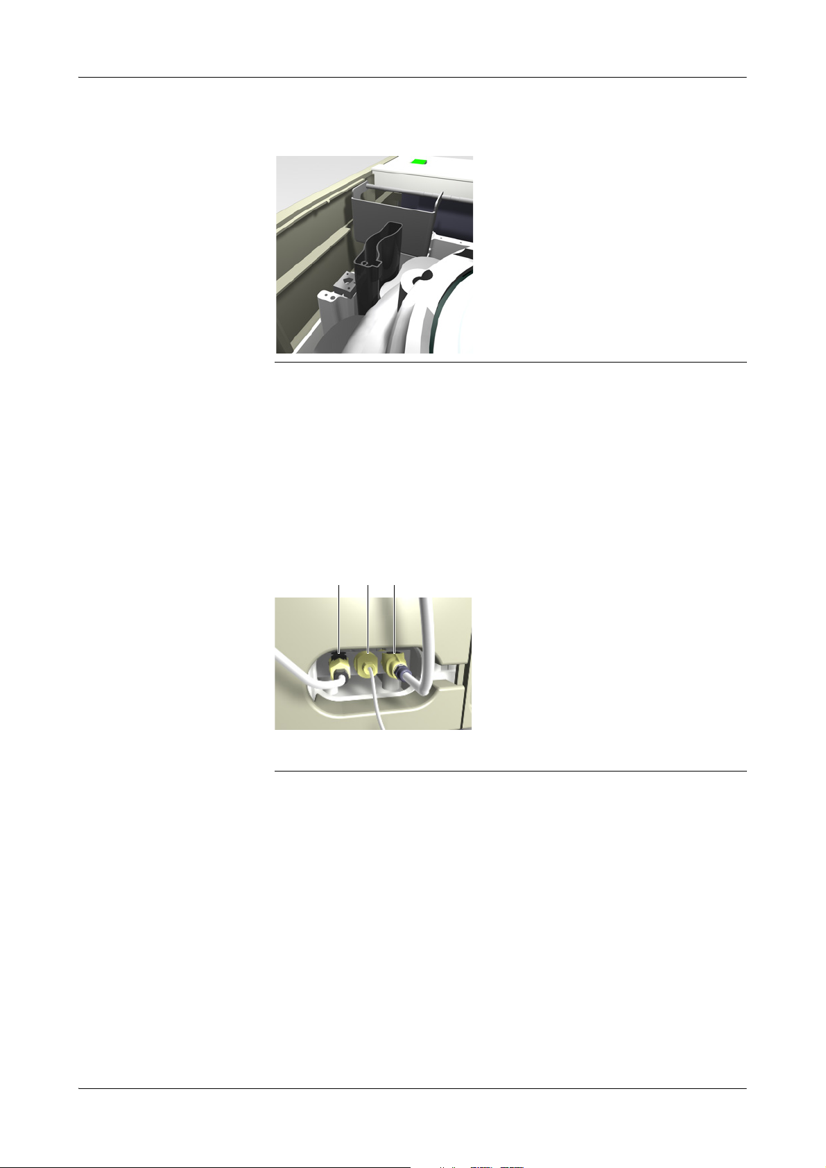
cobas c111 3Hardware
A B C
Hardware overview
Wash station
Figure A-13 Wash station
The probe is washed after each pipetting. It is lowered in the wash station and then
cleaner is pumped through the probe to wash it in and outside. Next water is pumped
through the probe to flush away the cleaner.
The wash station is connected by tubing to the internal waste container.
External fluid connectors
The three external fluid containers must be properly connected before you switch on
the cobas c 111 instrument.
A Water connector
B Cleaner connector
Figure A-14 External fluid connectors
C Waste connector
Roche Diagnostics
Operator’s Manual · Version 3.0 A-47
Page 58

3 Hardware cobas c111
A
C
B
Hardware overview
Transfer unit
The transfer unit moves the probe to the correct positions for all pipetting and
cleaning actions.
The following figure shows the major parts of the transfer unit.
A Transfer head
B Probe holder carriage
Figure A-15 Major elements of the robotic transfer unit
Transfer head The transfer head moves horizontally (along the X-axis); the probe moves up and
down (Z-axis), and it performs a rotational movement for mixing the cuvette and
reagent bottle content.
Transfer head arrest When the transfer head is obstructed in its horizontal movement, it immediately
stops. All pipetting and processing actions stop.
C Transfer X guide rail
Roche Diagnostics
A-48 Operator’s Manual · Version 3.0
Page 59
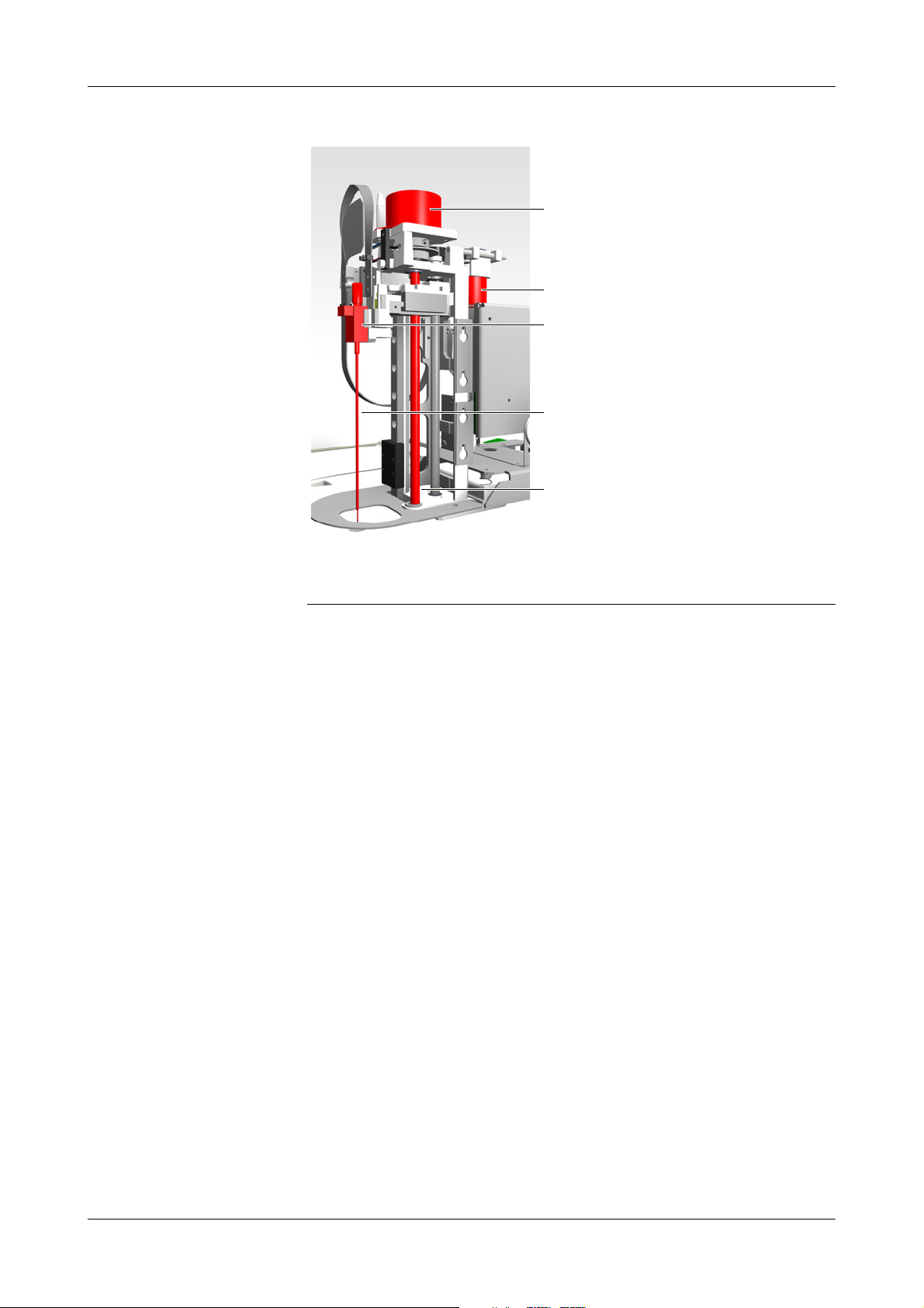
cobas c111 3Hardware
A
B
D
E
C
Hardware overview
A Mixing motor
B Tra nsfer Z mo to r
C Probe holder
Figure A-16 Transf er h e ad
Mixing motor The mixing motor is mounted on the carriage. When running, it generates a circular
movement of the probe. This movement is used for mixing the content of cuvettes
and reagent bottles.
Probe The probe has a flat tip. This is required for tube bottom detection. Because such a
probe cannot pierce a bottle cap, all bottles must be placed on the instrument with
their caps removed.
Level detection A sensor detects when the probe enters a fluid. On the basis of this level, the system
establishes whether there is enough fluid to perform the scheduled pipetting action.
Tube Bottom detection A physical sensor is activated as soon as the probe touches the bottom of a sample
tube.
This mechanism also works when the probe touches an object outside the tube. In
both cases, probe action stops and an appropriate alarm message is generated.
D Probe
E Mixer movement axis
Roche Diagnostics
Operator’s Manual · Version 3.0 A-49
Page 60

3 Hardware cobas c111
B
A
C
Hardware overview
Fluid containers
The following table shows which container is used for which fluid:
Fluid Container(s) Position
Sample Tube Sample area
Control Tube Sample area
Calibrator Tube Sample area
Diluent Reagent bottle Reagent disk
System cleaner External cleaner bottle External fluid rack
Cleaner Reagent bottle Reagent disk
Reagent Reagent bottle Reagent disk
Water Bottle External fluid rack
Waste Bottle External fluid rack
Ta b l e A - 5 Fluid containers, what they are used for and where
The term tube includes all kinds of tubes, as long as their dimensions lay within prescribed
limits. It also includes secondary tubes (cups). See Tubes on page A-54.
Waste containers
Internal waste tank The internal waste tank collects the waste from the wash station and the ISE unit, if
A Tubing adapter
B External waste container
Figure A-17 Waste container
this is used. It also collects the condensation from the cooling assembly in the rotor.
The internal waste tank is connected by tubing to:
o External waste container
o Wash station
o Reagent cooler (condensation)
o ISE unit (if installed)
C Internal waste tank
Roche Diagnostics
A-50 Operator’s Manual · Version 3.0
Page 61

cobas c111 3Hardware
C
A
B
Hardware overview
External waste container The yellow external waste container is placed on the external fluid rack. It is designed
to be washed and reused.
Because the system periodically performs wash actions, an external waste container
must be connected at all times. Therefore, when you empty the waste container, you
immediately replace it with the spare container and then empty the original
container. (The instrument is supplied with a spare waste container.)
There is no active level monitoring for the external waste container, but you are
notified if the external waste container has not been emptied for more than one day.
The external waste container is connected by tubing to the internal waste tank.
e
See Connecting and disconnecting the external fluid containers on page B-127.
See Checking the status of the external fluid containers on page B-15.
See maintenance action Clean the water and waste containers on page C-16.
Water container
The white water container is positioned on the external fluid rack. Attached to the cap
is a suction tube, which is equipped with a water filter.
There is no active level monitoring for the water container, but you are notified if the
water container has not been refilled for more than one day.
The water container is designed to be washed and refilled.
A Tubing
B Container
Figure A-18 Water container
The water container is connected by tubing to:
o Wash pum p
o Syringe assembly
o Probe
e
See Connecting and disconnecting the external fluid containers on page B-127.
See Checking the status of the external fluid containers on page B-15.
See maintenance action
See maintenance action Replace water inlet filter on page C-19.
Clean the water and waste containers on page C-16.
C Water inlet filter
Roche Diagnostics
Operator’s Manual · Version 3.0 A-51
Page 62

3 Hardware cobas c111
A
B
Hardware overview
Cleaner bottle
The cleaner bottle is positioned on the external fluid rack. It is designed to be replaced
when empty.
Level monitoring for the cleaner bottle is based on the number of cleaning and
pipetting actions that were performed.
A Tubing adapter B Cleaner bottle
Figure A-19 Cleaner bottle
When delivered, the bottle has a white cap. During installation, this is replaced by a
red cap with tubing attached to it (tubing adapter).
The cleaner bottle is connected by tubing to:
o Syringe assembly
o Probe
e
See Connecting and disconnecting the external fluid containers on page B-127.
See Checking the status of the external fluid containers on page B-15.
Roche Diagnostics
A-52 Operator’s Manual · Version 3.0
Page 63

cobas c111 3Hardware
WARNING
Hardware overview
Reagent bottles
The cobas c111 instrument works exclusively with reagent bottles
that are equipped with a two-dimensional barcode.
Each bottle holds up to 20 mL of fluid. The actual volume depends
on the test.
Place the bottles on the reagent disk as instructed by the software.
Reagents are handled in reagent sets. A set consists of up to three
reagents. You always load and replace all bottles of a set.
Chimneys
Chimneys are bottle inserts that reduce evaporation.
For reagents that are especially sensitive to concentration changes,
Roche recommend using chimneys on the reagent bottles. (See the
package inserts of the tests whether you should use chimneys or
not.)
To generally reduce evaporation, you may use chimneys on all
reagent bottles.
Incorrect results due to declining reagent quality
If the application definitions (see package insert) recommend the use of chimneys, the
corresponding calibration intervals apply to conditions when working with chimneys.
Roche recommend using chimneys whenever this is recommended on the test insert.
Roche Diagnostics
Operator’s Manual · Version 3.0 A-53
Page 64

3 Hardware cobas c111
WARNING
NOTICE
Hardware overview
Tu be s
The cobas c111 instrument can use both primary and secondary tubes (cups).
You can use any type of primary tube, as long as their dimensions lay within
prescribed limits.
o Maximum height (including secondary tube): 102 mm
o Minimum height: 70 mm
o Maximum outside width: 16.3 mm
o Minimum outside width: 11.8 mm
Incorrect results due to insufficient fluid
Insufficient fluid may lead to inaccurate pipetting and consequently to incorrect results.
Always fill the tubes with sufficient fluid that at the end of the pipetting process at least the
dead volume of fluid is left.
e
See Tubes on page A-54.
Incorrect results due to inappropriate tube and cup placement
Inappropriate tube and cup placement may lead to inaccurate pipetting and consequently
to incorrect results.
Make sure that the primary tubes are placed centrally and perfectly vertically in the holders in the sample area and that they are inserted firmly.
Make sure that secondary tubes are placed centrally on the primary tubes and that they
rest fully on them.
Probe damage due to not removing primary tube caps
The probe is not designed to pierce tube caps. It can get damaged when trying to pierce
tube caps.
Always remove the caps of primary tubes before placing them on the instrument.
The following table lists a few typical tubes that are suitable, and it gives the dead
volume for each of them.
Tube name Dead volume
13 x 75 mm 500 µL
13 x 100 mm 500 µL
16 x 75 mm 700 µL
16 x 100 mm 700 µL
Ta b l e A - 6 Typical examples of suitable tubes
Roche recommend using approved cups only. The following table lists the approved
cups.
Cup name Dead volume Placement
Hitachi standard cup 75 µL for 2 µL sample volume Directly on sample area
Hitachi micro cup 50 µL for 2 µL sample volume Directly on sample area
Roche Diagnostics Standard
false bottom tube
Ta b l e A - 7 Typical examples of suitable tubes
75 µL for 2 µL sample volume Directly on sample area
The Hitachi standard and micro cups can be placed on top of 16 x 75 mm tubes.
Roche Diagnostics
A-54 Operator’s Manual · Version 3.0
Page 65
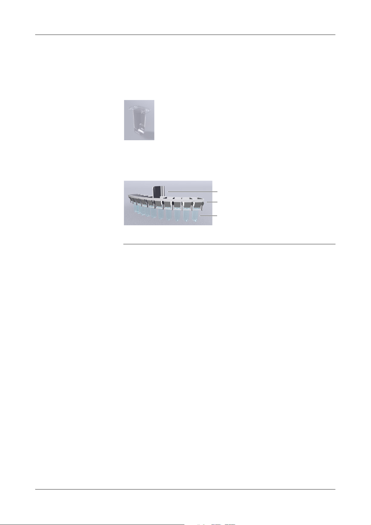
cobas c111 3Hardware
A
B
C
Hardware overview
Cups with a rim can be placed directly on the sample area, whereas cups without rim
must be placed on top of primary tubes.
Cuvettes
All optical measurements are made using the same transparent
plastic containers, called cuvettes. Samples are automatically
transferred from a sample tube to the cuvettes on the cuvette ring.
Cuvettes are disposable to eliminate carry-over.
Cuvette segments
Each segment holds 10 cuvettes.
A Segment handle
B Cuvette segment holding individual cuvettes
Figure A-20 Cuvette segment
C Cuvettes
Roche Diagnostics
Operator’s Manual · Version 3.0 A-55
Page 66
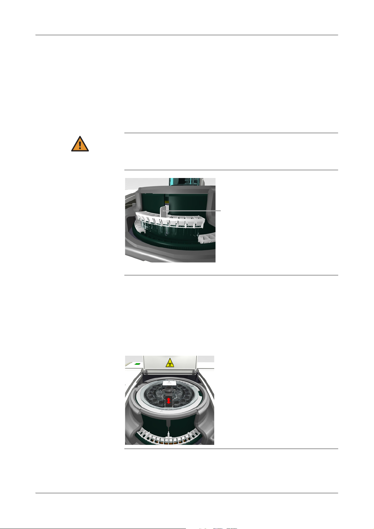
3 Hardware cobas c111
WARNING
A
Hardware overview
Handling cuvettes
Cuvettes are supplied in boxes containing cuvette sets. Each set contains a number of
cuvette segments. This way, the cuvettes can easily be handled without touching them.
Loading and removing cuvettes is guided by the system software. When handling is
required, the rotor moves the cuvette segments to the cuvette port, where you can
load or remove them. You handle one segment at a time. Cuvette segments are placed
in the cuvette ring of the rotor.
e
See Preparing cuvettes on page B-28.
Incorrect results due to scratched or soiled cuvettes
Scratches and impurities on the cuvettes distort the measurements.
Do not touch the cuvettes and make sure they do not touch other items when handling
them.
Reagent handling
A Hold the segment by its handle. Make sure not to touch the cuvettes.
Figure A-21 Handling a cuvette segment
Loading and removing reagents is guided by the system software. When handling is
required, the rotor moves the bottles to the reagent port, where you can load or
remove them. You handle one reagent bottle at a time. Reagent bottles are placed on
the reagent disk.
e
See Preparing the reagents on page B-22.
Figure A-22 Handling a reagent bottle
Roche Diagnostics
A-56 Operator’s Manual · Version 3.0
Page 67
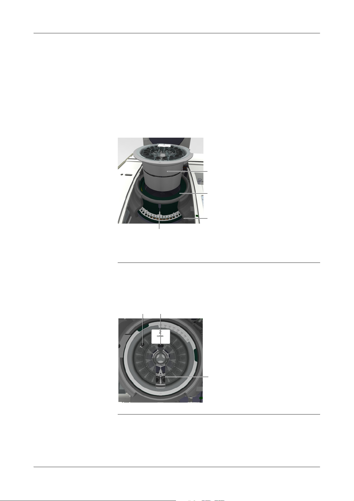
cobas c111 3Hardware
A
D
C
B
A
B
A
Hardware overview
Rotor
The rotor provides the following features:
o Space for up to 27 reagent bottles (on the reagent disk)
o Space for up to 60 cuvettes (in the cuvette ring)
o A cooled environment for reagents (reagent cooler)
o A temperature controlled environment for samples (cuvette ring)
o A synchronized transport mechanism to move reagent bottles and cuvettes to the
pipetting, loading, and measuring positions.
A Reagent disk
B Reagent cooler
Figure A-23 Main rotor elements
Rotational movement The bottles and cuvettes are positioned in a manner that they can be moved to the
various positions by a rotational movement. There are positions for loading and
removal (reagent and cuvette ports), pipetting, and measuring.
A Pipetting positions B Reagent port
C Temperature controlled cuvette ring (not
visible)
D Cuvette segment
Figure A-24 Reagent port on the reagent disk
Roche Diagnostics
Operator’s Manual · Version 3.0 A-57
Page 68
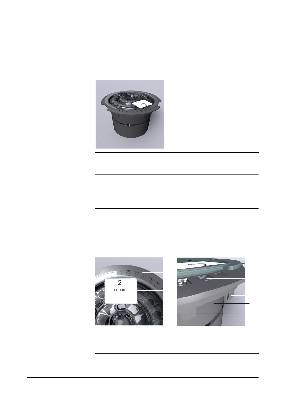
3 Hardware cobas c111
NOTICE
B
A
A
D
C
C
Hardware overview
Reagent disk
The reagent disk holds up to 27 reagent bottles. It is designed to be handled as one
unit, including the bottles. When not used on the instrument, the reagent disk is
placed in a container and stored in a refrigerated place.
Figure A-25 Reagent disk
Damage to the reagent disk
The reagent disk is designed to handle reagents while it is loaded on the instrument. The
cover is equipped with a locking mechanism.
Always remove and load reagents while the reagent disk is on the instrument and by using
the software supported procedures.
e
See Preparing the reagent disk on page B-21.
Reagent disk ID You can use up to eight different reagent disks on one cobas c111 instrument. Each
reagent disk is equipped with numbered tabs. For automatic disk identification by the
instrument, one—and only one—of these tabs is removed. The number of this
removed tab is the disk ID. When you label the disk, make sure that the number on
the label corresponds to that of the removed tab.
A Reagent disk IDs. There are eight possible
IDs.
B Disk label. The number must correspond to
Roche Diagnostics
A-58 Operator’s Manual · Version 3.0
the reagent disk ID.
Figure A-26 Reagent disk ID
C Identification tabs
D The tab has been removed for automatic
disk recognition
Page 69
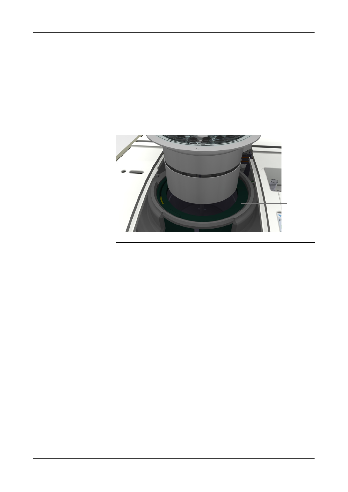
cobas c111 3Hardware
A
Hardware overview
Reagent disk container
For storage outside the instrument, the reagent disk is placed in a container. This
reduces evaporation of reagents and prevents their contamination.
Reagent cooler
The reagent cooler holds the reagent disk with its reagent bottles. The temperature in
the cooler is kept within the range of 6 to 10°C.
A Reagent cooler
Figure A-27 Reagent cooler
e
See maintenance action Clean reagent disk and sample area on page C-14.
Roche Diagnostics
Operator’s Manual · Version 3.0 A-59
Page 70

3 Hardware cobas c111
A
B
Hardware overview
Cuvette ring
The cuvette ring holds up to 6 cuvette segments, each containing 10 cuvettes.
A Cuvette ring B Cuvette segment
Figure A-28 Cuvette ring
Cuvettes fit neatly in the cuvette ring, without touching the walls when being moved
along the ring.
e
See Preparing the reagents on page B-22.
See maintenance action Clean reagent disk and sample area on page C-14.
Roche Diagnostics
A-60 Operator’s Manual · Version 3.0
Page 71

cobas c111 3Hardware
WARNING
A
B
Hardware overview
Barcode scanner
A hand-held barcode scanner is used for reading barcoded labels.
Loss of sight
The intense light of the LEDs may severely damage you eyes. Do not stare into the LEDs.
Scanning equipment using LED technology is covered by the international standard IEC
60825-1 LED Safety: Class 1.
A Barcode scanner B Scanner connector on the instrument
Figure A-29 Hand-held barcode scanner
Connect to the lower COM2 port
Always connect the barcode scanner to the lower of the two serial communication connectors (B).
e
For information on how to use the barcode scanner, see Using the barcode scanner on
page B-89.
The following containers are always supplied with barcodes:
o Reagent bottles
o Diluent bottles
o Auxiliary fluids (diluents, cleaners etc.)
Sample tubes can be used with or without barcoded labels.
Reagent bottle barcode On the reagent bottles, barcode of the PDF417 format is used.
The barcode contains the following information:
o Part ID
o Lot number
o Expiration date
o Reagent volume
o Serial number of bottle
o Tes t dat a
Roche Diagnostics
Operator’s Manual · Version 3.0 A-61
Page 72
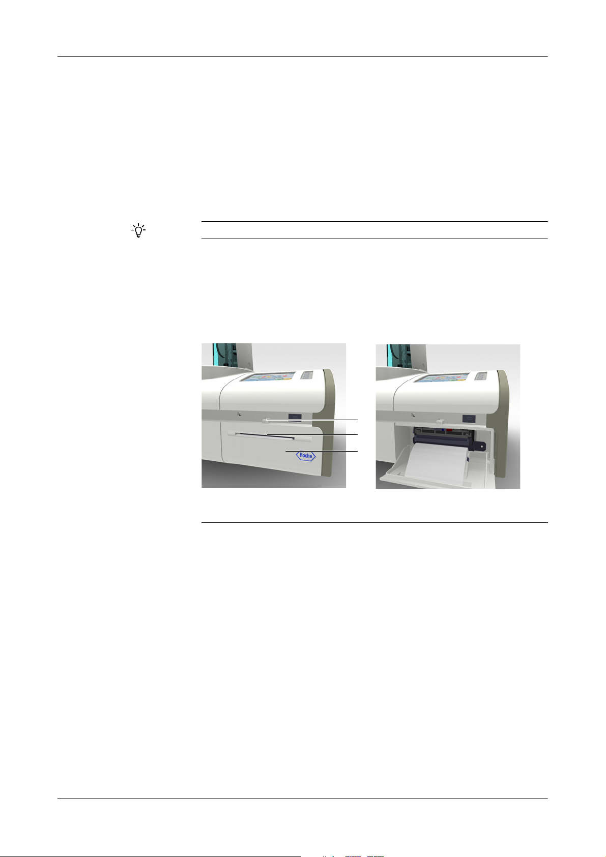
3 Hardware cobas c111
A
B
C
Hardware overview
Sample barcode The following barcode types are supported for sample tube identification:
o Codabar
o Codabar 2 of 7
o Code 3 of 9
o Code 128
o EAN
o Interleaved 2 of 5
o UPC (A, E)
A sample barcode must include a checksum at the end.
Printer
The cobas c111 instrument has a built-in thermal printer with a 112 mm paper roll.
The printer is used for example for printing placement lists, results, maintenance
action instructions, and status information on various items such as the loaded tests.
A Panel release button
B Paper slot
Figure A-30 Printer
e
See maintenance action Refilling printer paper on page B-122.
See To clear the paper jam on page D-46.
C Printer panel
Roche Diagnostics
A-62 Operator’s Manual · Version 3.0
Page 73
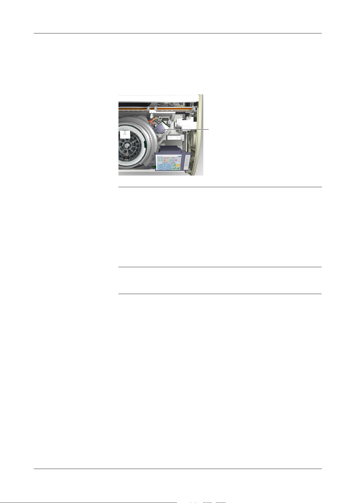
cobas c111 3Hardware
A
Hardware overview
Absorbance photometer
The cobas c111 main instrument uses the absorbance photometry measuring
method.
Absorbance photometer
A Photometer unit
Figure A-31 Photometer unit
Halogen lamp The Halogen lamp is mounted on a holder for easy replacement. The system informs
Wavelengths for the absorbance
photometer
Measurement principles
The measurements are taken without removing the cuvette from the rotor.
you when you need to replace the lamp.
e
See maintenance action Replace photometer lamp on page C-24.
For each cuvette, the absorbance photometer measures light intensity at 12 different
wavelengths:
340 nm 449 nm 520 nm 629 nm
378 nm 480 nm 552 nm 652 nm
409 nm 512 nm 583 nm 659 nm
e
See Principles of operation on page A-19.
Roche Diagnostics
Operator’s Manual · Version 3.0 A-63
Page 74

3 Hardware cobas c111
B
C
A
D
A
E
F
G
H
I J K
Hardware overview
Connectors
A Power supply
B Data and communication connectors
C Fluid connectors
D Front USB port (not shown)
E Serial communication connector
F Barcode scanner connector
Figure A-32 Connectors
G Maintenance connectors (Do not remove the
cable.)
H USB 2 connector (for troubleshooting)
I Water connector
J Cleaner connector
K Waste connector
Roche Diagnostics
A-64 Operator’s Manual · Version 3.0
Page 75

cobas c111 3Hardware
WARNING
A
B
Hardware overview
Fuses
Electrical shock by electronic equipment
Do not attempt to work in any electronic compartment. Installation, service, and repair
must only be performed by authorized and qualified personnel.
The mains fuses are situated at the rear of the instrument, above the power connector;
the internal fuses are situated on the right side of the instrument, at the top of the
connector panel.
A Power connector with T6.3 A H 250 V fuse B Low voltage fuses (T3.15 A)
F1: Heating system
F2: Motors
F3: Cooling assembly
Figure A-33 Fuses
e
See To change the mains fuses on page D-47.
See To change a low voltage fuse on page D-49.
F4: Photometer unit and LEDs
Roche Diagnostics
Operator’s Manual · Version 3.0 A-65
Page 76

4 cobas c111
NOTICE
Technical specifications
Technical specifications
Every effort has been made to ensure that all the information contained in these specifications is correct at the time of printing. However, Roche Diagnostics reserves the right to
make any changes necessary without notice as part of ongoing product development.
Physical dimension
Power requirements
Power requirements ISE unit
(optional unit)
Measurement principles
Width (with ISE unit) 590 mm (720 mm)
Depth (with ISE unit) 550 mm (550 mm)
Height (with ISE unit) 480 mm (480 mm)
Weight (with ISE unit) Approximately 32 kg (35 kg)
Line voltage 100-125 V and 200-240 V (-15%, +10%)
Line frequency 50 Hz (±5%) and 60 Hz (±5%)
Power consumption 250 VA
Insulation coordination Installation category II (IEC 61010-1)
Main fuse T6. 3 A H 250 V
Low voltage fuses T3. 15 A L 250 V
Battery Lithium 3.6 V 2.3 Ah SL-360/S
Line voltage 100-240 V (±10%)
Line frequency 50 Hz (±5%) and 60 Hz (±5%)
Supply voltage 19-24 V DC, Min. 2A
Power consumption 70 VA
Insulation coordination Installation category II (IEC 61010-1)
Absorbance photometry (enzymes, substrates, drugs of abuse)
Potentiometry ISE (ion selective electrodes) Na
+
, K+, Cl
-
Environmental conditions
Throughput
Samples
Roche Diagnostics
A-66 Operator’s Manual · Version 3.0
Temperature Running conditions: 15-32°C
Transport and storage: -25 to +60°C
Humidity Running conditions: 30-80% at 15-32°C, non
condensing.
Transport and storage: 10-95%, non condensing
Pollution Degree 2 (IEC 61010-1)
Altitude Max. 2000 m above sea level
Photometric 85 tests/h max.; 60 tests/h consolidated (with typical test
panel)
ISE 180 tests/h max.; 60-100 tests/h consolidated
(photometric and ISE mixed)
Sample handling Manually by operator
Time to first result 5-10 min (photometric measurements)
2 min (ISE measurements)
Page 77

cobas c111 4
Technical specifications
Water purity
Calibrators
Reagent bottles
Cuvettes
Minimum requirements Electrical resistivity [MΩ*cm @ 25°C] > 1
Electrical conductivity [µS/cm @ 25°C] < 1
Silicate (SiO
Particulate matter size [µm] n/a
Bacteria [CFU/mL] < 1000
Whenever the term "purified water" is used in this document, water of at least the quality
specified above must be used.
Roche recommends using Reagent Grade water.
Roche calibrators See the package inserts of the reagents.
Reagent bottles 20 mL maximum
Identification Barcode
Barcode 2-D, format PDF417
Number of tests 50-200 tests, depending on the test
Segments of 10 cuvettes Manual insertion and removal of segments
Single use Cuvettes are for single use only
Static incubation temperature in
cuvette
37°C ±0.5°C
) [mg/L] < 0.1
2
Photometer
ISE unit
Software data handling
Mass storage
Interfaces
Absorbance photometer 20 W halogen lamp
12 wavelengths 340-659 nm
Sensor Photosensitive diode array
Ion-selective electrode Indirect measurement
Sample volume 15 µL; Dilution 1:6 (1 part sample, 5 parts water)
3 Electrodes
1 ISE Reference Electrode
Operating system o LINUX
CPUs Intel XScale
Memory system o Flash ROM
External USB memory stick
Internal Flash ROM
USB1.1/2.0 For backing up data or loading data on the system
USB1.1/2.0 Modem
2 x RS232 Host, barcode scanner
Na, K, Cl
o VX Works
o DRAM
o SRAM
(memory stick)
Display
Printer
Roche Diagnostics
Operator’s Manual · Version 3.0 A-67
Color touchscreen 5.7 inch active matrix (1/4 VGA, 320 x 240 pixels)
Internal thermal printer Paper width 112 mm
Page 78

4 cobas c111
Technical specifications
Roche Diagnostics
A-68 Operator’s Manual · Version 3.0
Page 79

cobas c111 5Software
Table of co ntents
Software
Getting the most out of the instrument
In this chapter, you will find information on how to operate the instrument by using
the touchscreen. You will find out about the concept of wizards and you are
introduced to the key screens.
In this chapter
Introduction ..............................................................................................................A-71
Screen layout ..............................................................................................................A-72
Display items .............................................................................................................A-73
Color concept ......................................................................................................A-74
Workflows and wizards ............................................................................................. A-74
Navigation ............................................................................................................A-74
Working with the user interface ...............................................................................A-75
Adjusting the touchscreen ...................................................................................A-75
Scrolling ...............................................................................................................A-75
Expanding and collapsing lists ............................................................................A-76
Typing text ...........................................................................................................A-76
Using the filter function ......................................................................................A-78
Printing information ...........................................................................................A-80
Using online Help ................................................................................................A-81
Messages ...............................................................................................................A-82
Message screen ...............................................................................................A-82
Alarm monitor ............................................................................................... A-82
Key screens .................................................................................................................A-84
Overview tab ........................................................................................................A-84
Sample overview ............................................................................................ A-86
Orders ............................................................................................................A-87
STAT ...............................................................................................................A-89
Tests ................................................................................................................ A-90
Log off ............................................................................................................ A-92
Prepare ...........................................................................................................A-92
End shift .........................................................................................................A-92
Cuvette status .................................................................................................A-92
Chapter
5
Roche Diagnostics
Operator’s Manual · Version 3.0 A-69
Page 80

5Software cobas c111
Tab l e o f c o nt en ts
Disk and reagent status ................................................................................. A-93
ISE status ........................................................................................................A-94
System status .................................................................................................. A-95
Workplace tab ......................................................................................................A-97
Orders ............................................................................................................A-98
Result list ........................................................................................................A-99
QC status list ................................................................................................ A-101
QC history ................................................................................................... A-102
Calibrations list ............................................................................................A-104
Lot data ........................................................................................................A-105
Lot list ..........................................................................................................A-106
Loadlist .........................................................................................................A-107
Worklist ........................................................................................................A-107
Utilities tab .........................................................................................................A-108
Configuration .............................................................................................. A-109
Maintenance ................................................................................................A-110
Applications related functions ....................................................................A-111
Applications .................................................................................................A-112
Extra wash cycles .........................................................................................A-113
Host codes .................................................................................................... A-113
Reagent mixing ............................................................................................A-114
Process sequence ..........................................................................................A-115
Diagnostics ................................................................................................... A-116
Inventory ......................................................................................................A-117
Import ..........................................................................................................A-118
Users .............................................................................................................A-119
Export ...........................................................................................................A-120
Stopping a run ...................................................................................................A-121
Color interpretation for LEDs ................................................................................A-122
Buttons .....................................................................................................................A-124
Roche Diagnostics
A-70 Operator’s Manual · Version 3.0
Page 81

cobas c111 5Software
Introduction
Introduction
To operate the cobas c111 instrument, you use its touchscreen. The design and
functional concept of the touchscreen support you in the way you work.
The following table lists the major items and characteristics of a cobas c111 screen
and describes their impact on the operation of the instrument.
Screen item Impact on operation
Screen types Distinct screen types make it easy for you to find your way
around the user interface. For example, you immediately
know whether you are on a main screen or whether you are
reading a message.
Screen layout The consistent layout allows you to quickly find the required
information and to locate the various display items.
Buttons Press a button to open and close a screen or to start a func-
tion.
Colors The color of an item on the screen points to its own status or
that of the item it represents.
The "traffic light" color scheme is used:
o Green: Everything is OK.
o Yellow: The system is working, but you need to intervene
for it to continue to do so.
o Red: This item does not work, you need to intervene.
Wizards A wizard denotes a predefined sequence of screens (steps)
that represent a certain task, for example defining an order.
By following the suggested sequence of steps you ensure the
proper execution of the tasks and functions.
With some critical tasks, you need to follow the wizard
exactly, right through to the end. In other cases, you may skip
a step and perform it later.
Ta b l e A - 8 The major items and characteristics of the touchscreen
Roche Diagnostics
Operator’s Manual · Version 3.0 A-71
Page 82
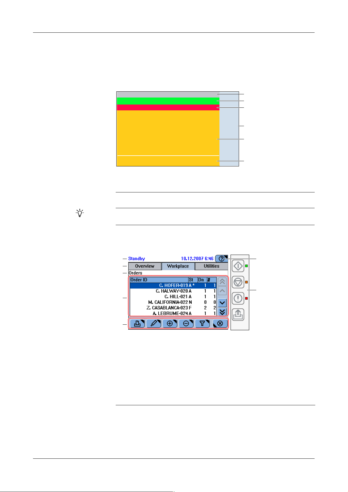
5Software cobas c111
A
D
B
C
E
D
F
G
F
D
E
C
B
A
Screen layout
Screen layout
All screens are based on the following layout:
A Status area
B Tab s
C Headline
Figure A-34 Basic screen layout
The screen representations shown in this chapter and throughout this manual are for illustrative purposes only. The screens do not necessarily show valid data.
D Global action area
E Working area
F Buttons area
Depending on the function of a screen, some layout items may not be displayed.
The following is an example of a screen with the full range of display items.
A The status line displays the system status.
B Tab s represent the major work areas. You
can switch to any of them any time.
C The headline characterizes the content or
function of the screen. If the screen is part of
a sequence of screens (wizard), the headline
tells you where you are within this sequence.
D The working area displays the main content
of the screen.
E The buttons vary depending on the content
of the working area and the screen position
within a series of steps (wizard).
F The Help button leads to concise information
that is relevant to the current screen and situation.
G The global action buttons represent the func-
tions that are permanently available: Start,
Stop, Alarm, Line Feed. The LEDs next to
them point to their status.
Figure A-35 Example of a screen
Roche Diagnostics
A-72 Operator’s Manual · Version 3.0
Page 83
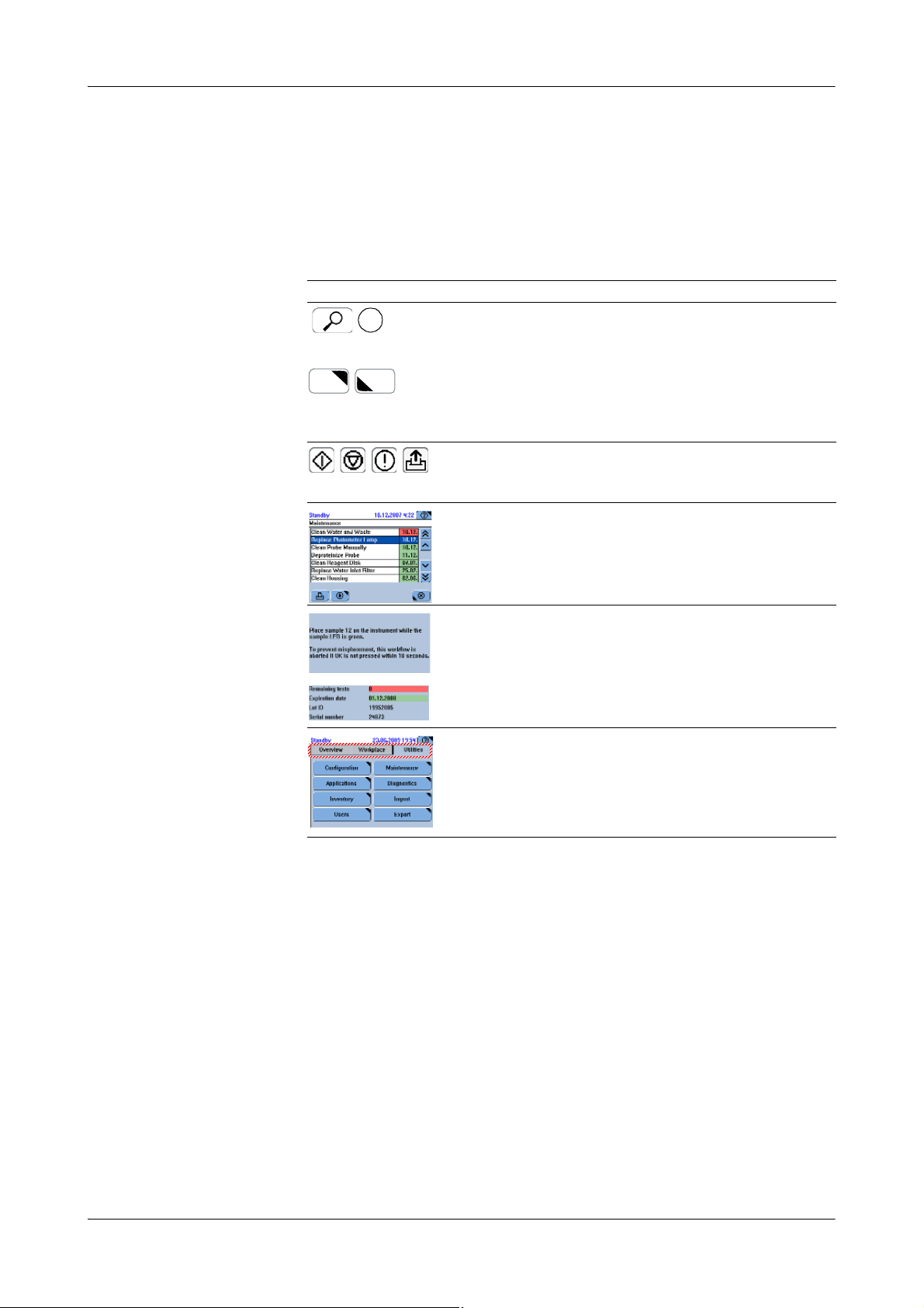
cobas c111 5Software
1*
Display items
Display items
The cobas c111 screens are made up of text areas and various kinds of display items
such as tabs and buttons.
The following table lists the major display items and describes their use.
Display item Use
Button Press a button to start a function. In addition, many
buttons also either open a new screen or close the
current screen.
A triangle in the top right corner of a button tells you
that a new screen will be displayed when you press
the button; a triangle in the bottom left corner that
the current screen will be closed.
Global action
button
List Press a list item to select it. (Its color turns blue.)
The global action buttons are positioned on the right
side next to the screen. The LED next to each of the
buttons indicates whether the button is active or not.
Use the scroll buttons to display the items that are
not visible.
Text Text usually provides information or instructions. It
Tab Tabs are used to group information into units that
Ta b l e A - 9 Major display items
can be color coded to indicate its importance level.
can be displayed on one screen.
Roche Diagnostics
Operator’s Manual · Version 3.0 A-73
Page 84
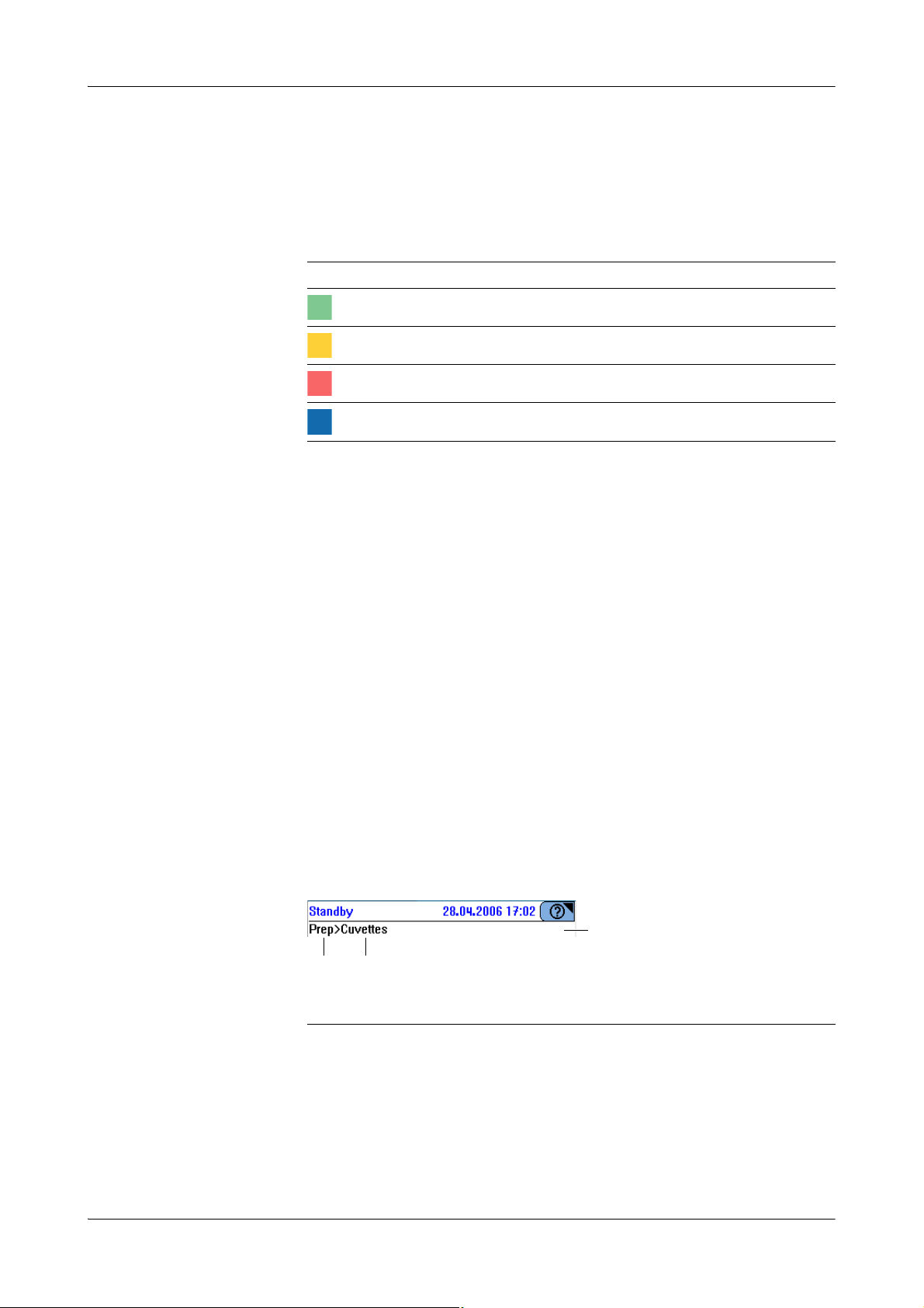
5Software cobas c111
BA
C
Workflow s and wizar ds
Color concept
The color of buttons and other display items tells you about the status of the display
item or the item it represents.
The cobas c111 instrument uses the familiar "traffic light" color scheme.
Color Meaning for buttons
Green The element is OK.
Yellow Your intervention is required to ensure continuous operation.
Red Your immediate intervention is required. Operation has stopped.
Blue The item is selected.
Ta b l e A - 1 0 Color concept
e
For details on the meaning of LED colors, see Color interpretation for LEDs on page A-122.
e
For details on the meaning of button colors, see the explanations in the relevant operation
instructions.
Workflows and wizards
Screens and sequences of screens help you perform your tasks. If not all steps of a task
can be performed from one screen, the workflow is realized as a sequence of screens, a
so-called wizard. cobas c 111 wizards do not usually force you to perform a task at a
certain stage, they just make your work easier.
Navigation
Moving from screen to screen You move from screen to screen with the help of buttons.
Knowing where you are Screens on which you perform tasks provide a headline that displays the navigation
path of the current screen.
A Button where you started
B Current position in the workflow
Figure A-36 Headline with navigation path
C Headline
e
For an overview of the navigation buttons, see Navigation functions on page A-126.
Roche Diagnostics
A-74 Operator’s Manual · Version 3.0
Page 85
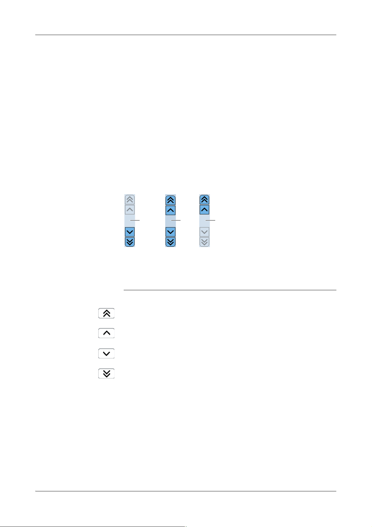
cobas c111 5Software
CA B
Working with the user interface
Working with the user interface
Adjusting the touchscreen
With a touchscreen, it is important that the point where you press the screen
corresponds exactly with its hardware equivalent. If this were not the case, pressing a
screen item such as a button might not lead to the expected result.
e
See Adjusting the touchscreen on page B-130.
Scrolling
If not all text or all list elements fit on one screen or display area, use the scrolling
function to display the hidden content.
A You are on the first page. You can scroll
down.
B There is text both before and after the
currently displayed text. You can scroll up
and down.
Figure A-37 Scroll bars
Scroll to the previous page.
Select the previous line and scroll if necessary.
Select the next line and scroll if necessary.
Scroll to the next page.
C You are on the last page. You can scroll up.
Roche Diagnostics
Operator’s Manual · Version 3.0 A-75
Page 86
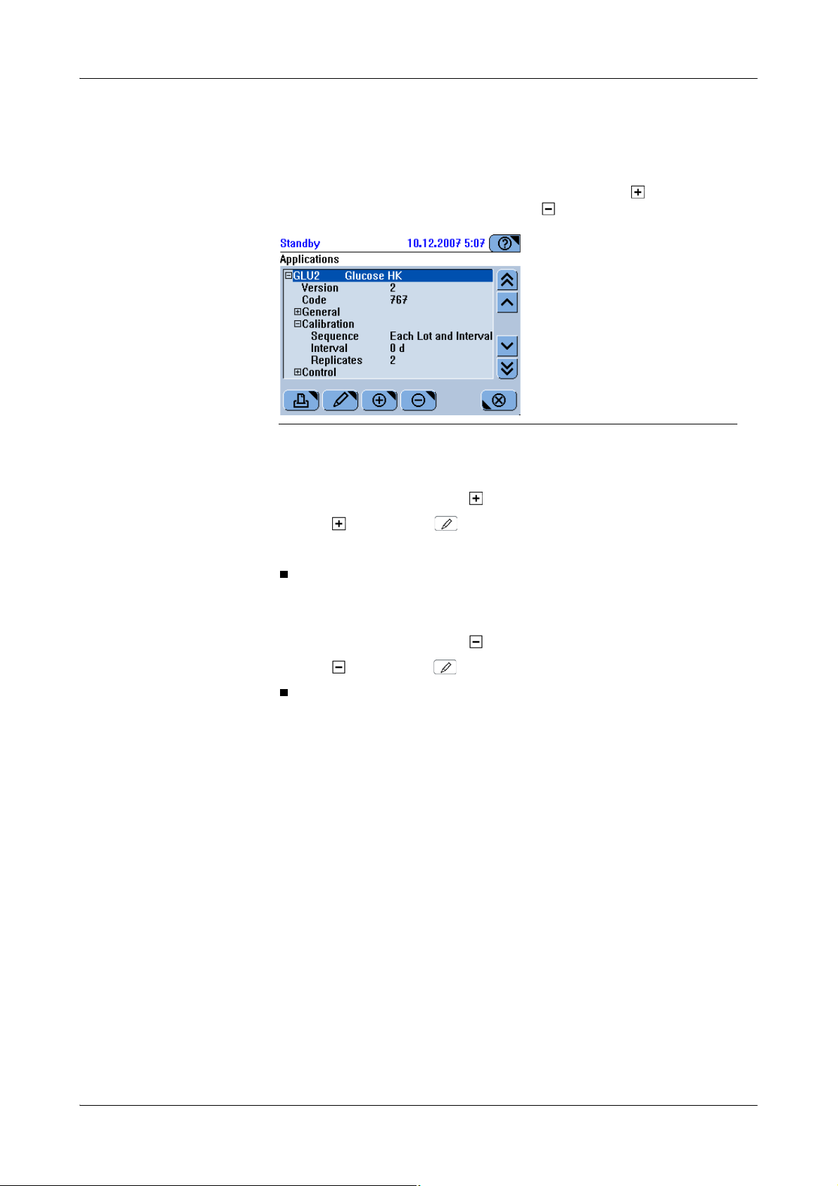
5Software cobas c111
Working with the user interface
Expanding and collapsing lists
In hierarchically structured lists, you initially see only the top level entries. List items
that contain (but hide) lower levels of entries are marked with . List items that
display lower levels of entries are marked with .
Figure A-38 Hierarchically structured list
a To expand a list
Typing text
1
Select a list item marked with .
2
Press again or press .
3
Use the scrollbar, if required, to display the items you are interested in.
a To collapse a list
1
Select a list item marked with .
2
Press again or press .
There are dedicated screens for typing alphanumeric and numeric characters.
You can choose from the following screens:
o Alphanumeric upper case
o Alphanumeric lower case
o Special characters
o Numeric characters
Roche Diagnostics
A-76 Operator’s Manual · Version 3.0
Page 87
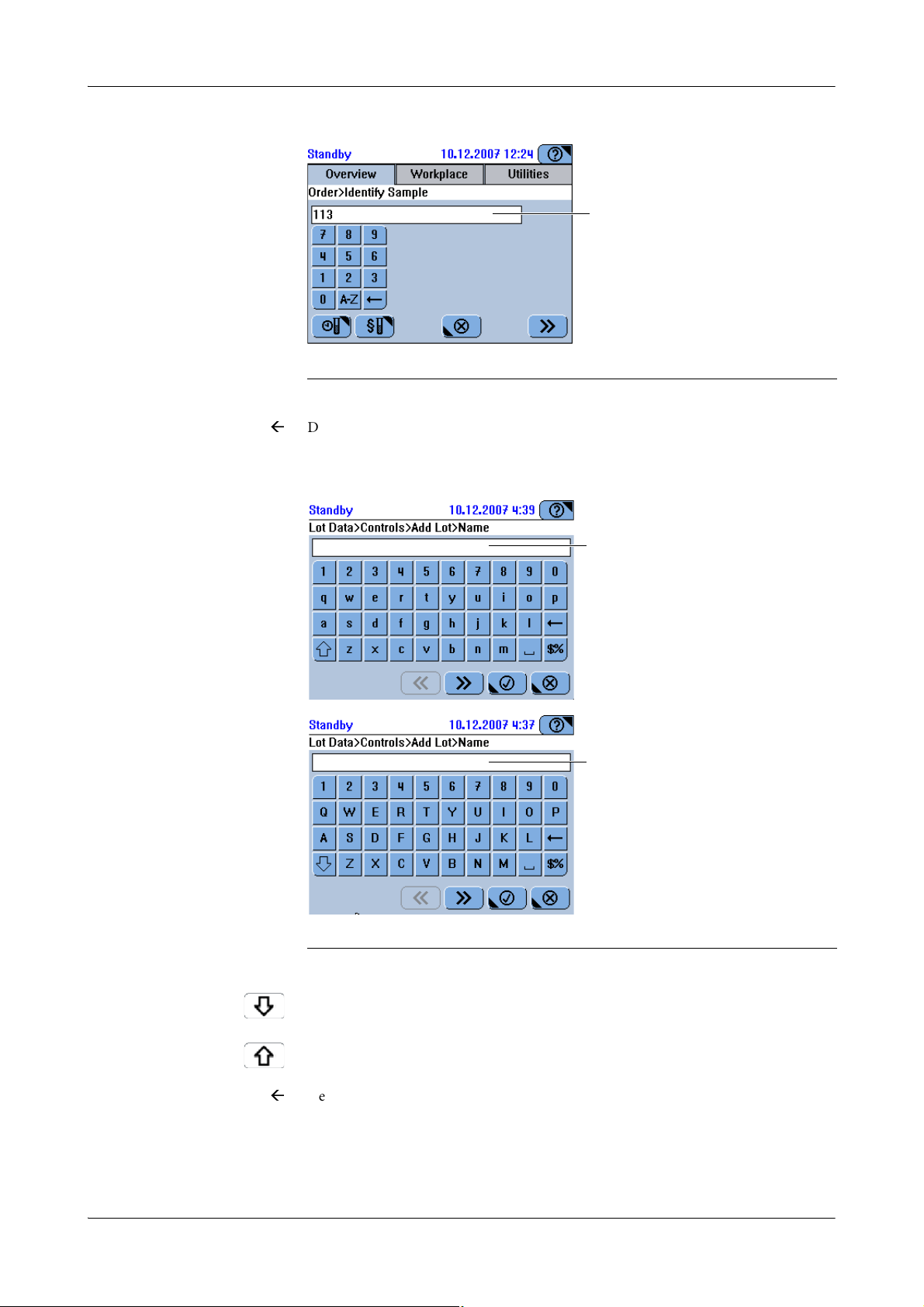
cobas c111 5Software
A
A
A
]
Working with the user interface
Numeric keyboard
A Typed text
Figure A-39 Numeric keyboard screen
Delete the last character displayed in the text line.
A-Z Switch to the uppercase alphanumeric keyboard.
Alphanumeric keyboards
A Typed text
Figure A-40 Upper and lowercase alphanumeric keyboard screens
Switch to the lowercase keyboard.
Switch to the uppercase keyboard.
Delete the last character displayed in the text line.
$% Switch to the special characters keyboard.
Press to insert a space.
Roche Diagnostics
Operator’s Manual · Version 3.0 A-77
Page 88
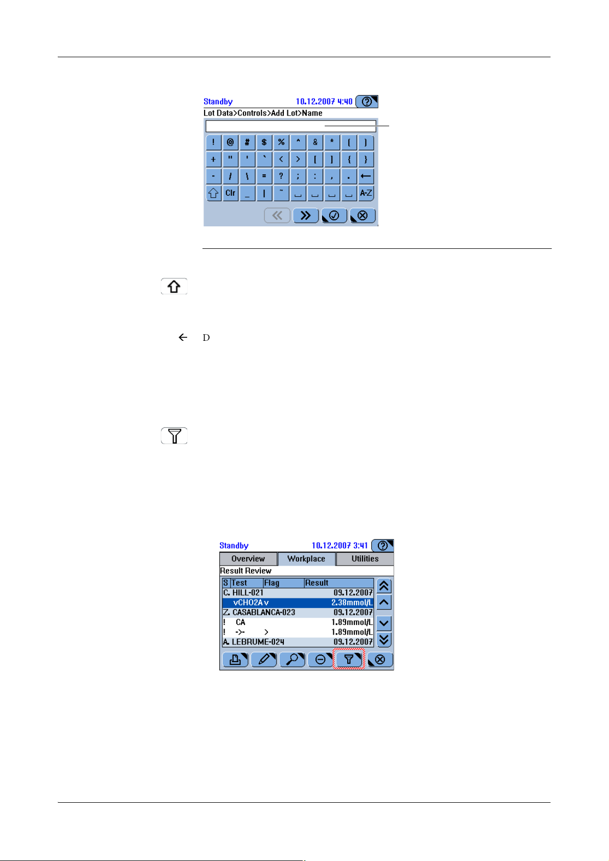
5Software cobas c111
A
]
Working with the user interface
Special characters keyboard
A Typed text
Figure A-41 Special characters keyboard screen
Switch to the lowercase alphanumeric keyboard.
A-Z Switch to the uppercase alphanumeric keyboard.
Delete the last character displayed in the text line.
Using the filter function
a To apply a filter to a list
Press to insert a space.
In many lists you can apply a filter, that is, you can select predefined criteria for
generating a selection of entries.
The way to apply a filter is the same in all screens where a filter is available. Here is an
example:
1
Display the list.
Roche Diagnostics
A-78 Operator’s Manual · Version 3.0
Page 89
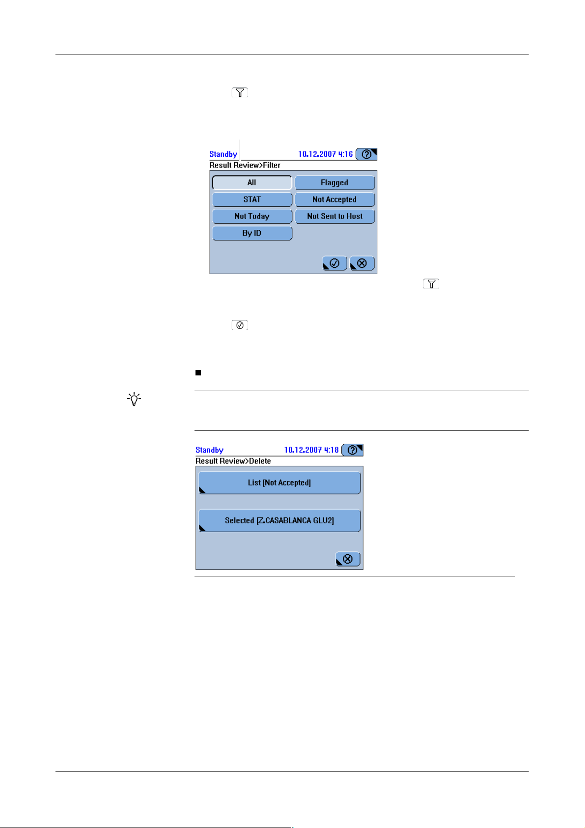
cobas c111 5Software
A
Working with the user interface
2
Press .
A screen is displayed for selecting the filter criterion.
A In the status line, the screen is indicated where you pressed .
3
Choose one of the filter options.
4
Press .
The list is displayed again. It now contains only the entries that comply with the
criterion you just applied by pressing its button.
After you have applied a filter, the criterion name will appear as part of the List button, for
example on screens for deleting data. If you used the Not Accepted filter criterion, the
List button would be called List [Not Accepted].
Figure A-42 List button names
Roche Diagnostics
Operator’s Manual · Version 3.0 A-79
Page 90

5Software cobas c111
A
Working with the user interface
Printing information
On many screens, you can print the contents of the working area on the built-in
printer. In many cases, a screen is first displayed for selecting the kind of data you
want to print. In these cases, the print button is marked with a triangle in the top
right corner .
a To print information
1
Press .
If filter criteria are available, a screen is displayed for selecting what data you want
to print. For example:
A In the status line, the screen is indicated where you pressed .
2
Choose one of the print options.
The appropriate data is automatically selected and printed.
Choose > to terminate the printing task, if required.
Roche Diagnostics
A-80 Operator’s Manual · Version 3.0
Page 91
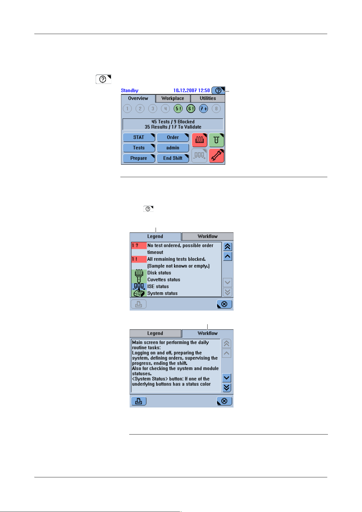
cobas c111 5Software
A
A
B
Working with the user interface
Using online Help
The Help button is a permanent feature of all screens.
A The Help button is always in the top right corner of the screen.
Figure A-43 Permanent Help button
a To display the Online Help
1
Press .
A The Legend tab describes the buttons and
Roche Diagnostics
Operator’s Manual · Version 3.0 A-81
their colors.
Figure A-44
B The Workflow tab provides additional
information on items on the screen or on
actions you can perform.
Page 92

5Software cobas c111
A
B
Working with the user interface
2
Use the scroll bar to display the hidden information.
e
For details on scrolling, see Scrolling on page A-75.
Messages
Messages are displayed in two ways:
o Immediate feedback on user actions is displayed in a pop-up message screen.
o Information concerning a problem that occurred during operation is reported in
the alarm monitor.
Message screen
Message screens are displayed automatically as soon as the message is generated.
Alarm monitor
Alarm button and LED
Figure A-45 Message screen
Read the message and press to close the screen.
Messages concerning an irregularity that occurred during operation can be viewed in
the alarm monitor. The alarm LED alerts you when such messages are generated. It is
turned off when all alarm messages are confirmed.
The Alarm button is always active, even if nobody is logged on the system.
A Alarm LED B Alarm button
Roche Diagnostics
A-82 Operator’s Manual · Version 3.0
Figure A-46 Alarm LED
Page 93

cobas c111 5Software
B
D
A
C
E
Working with the user interface
Interpreting the alarm LED
No color, off There are no unconfirmed alarm messages.
Ye l l o w There is at least one unconfirmed alarm message. You need to deal with it as soon as
possible.
Red There is at least one unconfirmed alarm message. You need to deal with it
immediately, processing may not be able to continue unless you do so.
Acoustic signal An acoustic signal is sounded when an alarm is generated. You can adjust the volume
(Utilities > Configuration > System > Vo lu m e ).
a To display alarm messages
1
Press .
2
Use to limit the number of messages that are contained in the list.
3
Select the message you are interested in.
Alarm message
Detailed alarm message
A Alarm ID
B Total number of messages in the list.
C Display the previous alarm message.
Figure A-47
4
Press to display the detailed message.
D Problem description and short remedy
suggestion
E Display the next alarm message.
e
For details on handling alarm messages, see Reacting to alarm messages on page D-7.
Roche Diagnostics
Operator’s Manual · Version 3.0 A-83
Page 94

5Software cobas c111
C
A
B
Key screens
Key screens
The screen representations shown in this chapter and throughout this manual are for illustrative purposes only. The screens do not necessarily show valid data.
The main screen is divided into tabs. These tabs represent distinct work areas.
f The Overview tab is your main work area when performing the daily routine tasks.
o Use the Wo rk pl a ce to gain information on orders and the corresponding results.
You can also start the lot handling functions from this tab.
o Use the Utilities tab to perform tasks that are not normally part of the routine
analysis workflow. Typically, these would be administration and maintenance
tasks.
The following sections describe the key screens of these tabs and point out the main
tasks you can perform on them.
Overview tab
The Overview tab is your main work area when performing the daily routine tasks.
A Tube icons
B Status of current order processing
Figure A-48 Overview tab
Show details about the order for this sample.
STAT Define STAT orders.
Order Define routine orders.
C Buttons
Te s t s Check the status of the currently installed tests.
Log off, (Log on) Log off or on the system.
If somebody is logged on, your user name is displayed, for example admin; if nobody
is logged on, Log on.
Prepare Perform the preliminary tasks at the beginning of a shift.
End Shift Perform the necessary tasks when ending the shift.
Roche Diagnostics
A-84 Operator’s Manual · Version 3.0
Page 95

cobas c111 5Software
Key scre ens
Check the status of the reagent disk.
The reagents are OK.
Fewer than 10% of tests are left for a reagent set, or its expiration date has passed.
No or unidentified disk on board.
A reagent set is not complete or a reagent is empty.
Check the status of the cuvette segments currently loaded on the rotor.
More than one segment is available.
The last available cuvette segment is in use.
No cuvettes are available.
System Status The System Status button displays both the icon and the color of one of the buttons of
the underlying system status screen (see System status on page A-95).
The icons are first prioritized by color, first priority being red, followed by yellow and
green, and then according to the sequence in which they are listed below.
This button can show either of the following icons.
Analyzer (main cover)
Reagent cooler and cuvette ring temperature
Sample area ventilation
External fluid containers
Maintenance
Printer
Roche Diagnostics
Operator’s Manual · Version 3.0 A-85
Page 96
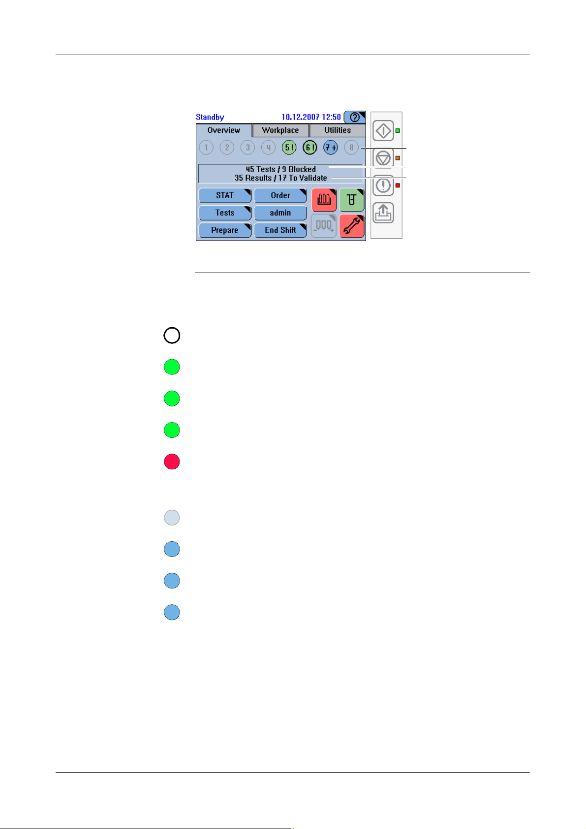
5Software cobas c111
C
B
A
111*1!1!11+1*1?
Key screens
Sample overview
A Sample tube buttons
B Open orders
Figure A-49 Sample tube status on the Overview tab
The number in the button indicates the position on the sample area.
A sample tube button with a wide edge symbolizes a STAT order.
All tests are completed and their results are accepted.
All tests are pipetted.
All tests are completed but not yet accepted.
All remaining tests are blocked for one of the following reasons:
o There is not enough sample fluid.
o The sample is not identified.
There is no sample on this position.
C Results
Tests are ordered. Processing has not yet started.
Tests are ordered, processing has started.
The sample is identified, but no tests were ordered yet.
If working in Order Query Mode: The order could not be obtained from the host.
Roche Diagnostics
A-86 Operator’s Manual · Version 3.0
Page 97

cobas c111 5Software
Key scre ens
Orders
f Overview > Order
Press Order to define routine orders.
The process of defining an order, and consequently which screens are displayed,
depends on how your cobas c111 instrument is integrated in your laboratory
infrastructure (barcodes, host connection).
Identifying samples
f Overview > Order
Typin g t h e sampl e I D
Figure A-50
Order Interval QC.
Order Default QC.
f Overview > Order
(If you work with barcodes, additionally press .)
Figure A-51
e
For information on how to use the keyboard screens, see Ty ping text on page A-76.
Order Interval QC.
Order Default QC.
Roche Diagnostics
Operator’s Manual · Version 3.0 A-87
Page 98
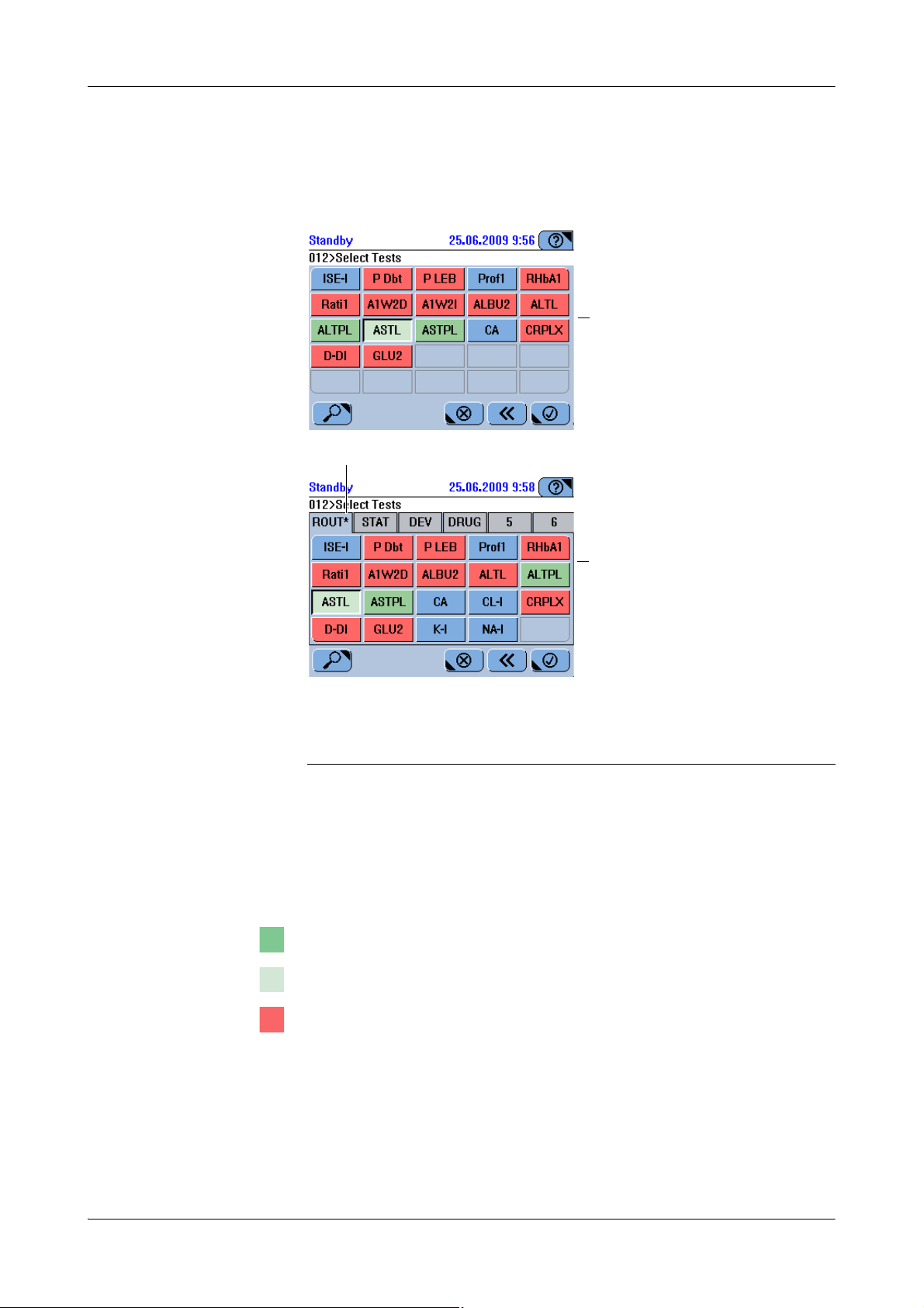
5Software cobas c111
A
B
C
CA
Key screens
Selecting tests, profiles, and
ratios,
f Overview > Order > identify sample
AEasy mode test-board, all tests fit on one
screen.
B Tabs marked with an asterisk contain
selected tests.
Figure A-52 Test selection screens
Tabs are used to group information into units that can be displayed on one screen.
The system administrator can define up to six test tabs, name them and assign tests,
profiles, and ratios to them.
The tests, profiles, and ratios are sorted alphabetically. Profiles and ratios precede the
tests, and they adopt the color of their tests.
The test is on board and ready for use.
The test has already been pipetted.
The test is blocked.
CFull mode test-board. The tests are grouped
in tabs.
Roche Diagnostics
A-88 Operator’s Manual · Version 3.0
Page 99

cobas c111 5Software
Key scre ens
The expiration date of the test has passed.
There are only few tests left.
A QC is due or its result has not been accepted.
A more recent version of the application has been imported.
For a development channel: An extra wash cycle is missing.
The test is defined but not on board.
A required diluent or cleaner is not on board.
Display a screen that contains information on the status of each test.
STAT
f Overview > STAT
Press STAT to define urgent (short turn-around time) orders.
The process of defining a STAT (short turn around time) order is identical to that of
defining a routine order. The difference lies in the scheduling of the tasks. When a
STAT order is defined, it will be the next order to be processed, irrespective of what
routine orders already exist. Existing STAT orders are finished first.
Roche Diagnostics
Operator’s Manual · Version 3.0 A-89
Page 100
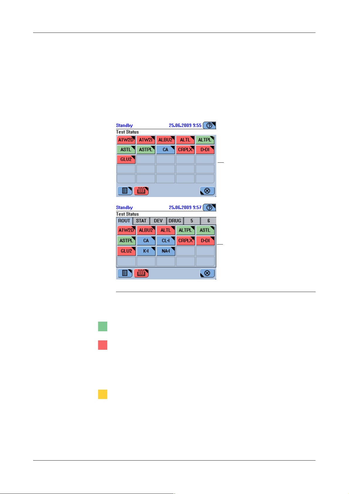
5Software cobas c111
A
B
Key screens
Te s t s
Displaying the test overview
f Overview > Te st s
Ta bs The tabs are displayed if you work with the order mode Full. They represent user-
defined test panels. If you work with the order mode Easy, all tests are on one panel
and there are no tabs.
A Test selection screen in order mode Easy. B Test selection screen in order mode Full.
Figure A-53 Test selection screen
The color of a test button represents its status:
The test is on board and ready for use.
The test is blocked for one of the following reasons:
o The calibration is due or failed.
o For the reagent set, the number of available tests is 0, or a reagent bottle is missing
(incomplete reagent set).
o Initial calibration is required.
The expiration date of the test has passed.
There are only few tests left.
A QC is due or its result has not been accepted.
A more recent version of the application has been imported.
For a development channel: An extra wash cycle is missing.
Roche Diagnostics
A-90 Operator’s Manual · Version 3.0
 Loading...