

Page 1
CoaguChek® Pro II
Operator’s Manual
Page 2

Revision History
Manual version Revision date Changes
Version 1.0 2015-11 New document
Version 2.0 2015-11 Revised safety information on barcode
handling, minor changes
Page 3

CoaguChek® Pro II
Operator’s Manual
Version 2.0
0 7154879001 (02) 2015-11 EN
Page 4

© 2015 Roche Diagnostics GmbH. All rights reserved
The contents of this document, including all graphics, are the property of Roche Diagnostics.
Information in this document is subject to change without notice. Roche Diagnostics shall not be
liable for technical or editorial errors or omissions contained herein. No part of this document
may be reproduced or transmitted in any form or by any means, electronic or mechanical, for any
purpose, without the express written permission of Roche Diagnostics.
Please send questions or comments about this manual to your local Roche representative.
ACCU-CHEK, COAGUCHEK and SAFE-T-PRO are trademarks of Roche.
All other trademarks are the property of their respective owners.
The Wi-Fi CERTIFIED Logo is a certification mark of the Wi-Fi Alliance.
4
Page 5

On the packaging and on the identification plate of the instrument you may encounter the
following symbols, shown here with their meaning:
Caution, consult accompanying documents. Refer to safety-related notes in the
instructions for use accompanying this product.
Temperature limitation (Store at)
Use by
Manufacturer
LOT
IVD
On meters with WLAN capability:
For other WLAN certifications, see label on bottom of battery compartment and addendum for
information on WLAN registration.
Batch code/ Lot number
Catalog number
In vitro diagnostic medical device
This product fulfills the requirements of the European Directive 98/79/EC on in vitro
diagnostic medical devices.
Consult instructions for use
The system fulfills the Canadian and U.S. safety requirements (UL LISTED, in
accordance with UL 61010A-1:02 and CAN/CSA-C22.2 No. 61010-1-04).
This device complies with Part 15 of the FCC Rules and with RSS-210 of Industry
Canada
5
Page 6

This page intentionally left blank.
6
Page 7

1 Introduction 11
1.1 Before you start......................................................................................................................................... 11
Intended use ...................................................................................................................................... 11
Important information regarding use ....................................................................................... 11
If you need help................................................................................................................................ 12
General note....................................................................................................................................... 12
What can the system do for you? .............................................................................................. 12
Test principle ..................................................................................................................................... 13
Contents of the pack ...................................................................................................................... 14
1.2 Important safety instructions and additional information......................................................... 15
Safety information............................................................................................................................ 17
Disposal of the system ................................................................................................................... 18
General care....................................................................................................................................... 18
Battery pack ....................................................................................................................................... 18
Electromagnetic Interference ...................................................................................................... 21
Touchscreen....................................................................................................................................... 21
Local Area Network: protection from unauthorized access ............................................ 21
Wired network connection ........................................................................................................... 22
Wireless connectivity ...................................................................................................................... 23
Radiofrequency radiation exposure information.................................................................. 23
Operating conditions ...................................................................................................................... 27
Quality control ................................................................................................................................... 27
1.3 Overview of the meter elements ....................................................................................................... 28
1.4 Buttons and icons overview ................................................................................................................. 30
1.5 Power supply.............................................................................................................................................. 33
2 Putting the Meter into Operation 35
2.1 Installing or replacing the battery pack........................................................................................... 36
Removing the battery pack .......................................................................................................... 37
Installing the battery pack ............................................................................................................ 38
2.2 Powering the meter on and off........................................................................................................... 41
Checking the software version ................................................................................................... 41
3 Meter Setup 43
Note on presentation of screen elements in this manual................................................. 43
3.1 Settings summary ................................................................................................................................... 45
3.2 Screen setup.............................................................................................................................................. 49
Contrast ............................................................................................................................................... 49
Result Units ........................................................................................................................................ 50
Result Confirmation......................................................................................................................... 51
Language Selection......................................................................................................................... 52
Setting the date................................................................................................................................. 53
Setting the time................................................................................................................................. 55
Setting the display options for date and time ....................................................................... 56
7
Page 8

8
3.3 Options setup ........................................................................................................................................... 58
Sort......................................................................................................................................................... 58
Beeper .................................................................................................................................................. 60
Auto Off................................................................................................................................................ 62
Connection.......................................................................................................................................... 63
QR Code............................................................................................................................................... 64
Computer............................................................................................................................................. 67
Printer ................................................................................................................................................... 68
Parameter Selection ........................................................................................................................ 69
3.4 ID Setup ....................................................................................................................................................... 70
System Administrator (Admin.)................................................................................................... 72
Operator ID ........................................................................................................................................ 76
Patient ID ............................................................................................................................................ 77
3.5 QC Settings setup .................................................................................................................................... 79
QC Range ............................................................................................................................................ 80
QC (quality control) Lockout........................................................................................................ 83
Operator Lockout ............................................................................................................................. 86
STAT Test Configuration................................................................................................................ 88
Scan QC Material ............................................................................................................................. 90
3.6 Diagnostics................................................................................................................................................. 91
4 Testing a Blood Sample 93
4.1 Important notes......................................................................................................................................... 93
Getting a good capillary blood sample .................................................................................... 95
Getting a good result from venous whole blood.................................................................. 96
4.2 Preparing to test ....................................................................................................................................... 97
Test strip code chip ......................................................................................................................... 97
Inserting the code chip .................................................................................................................. 98
Powering on the meter................................................................................................................... 99
4.3 Performing a test .................................................................................................................................. 102
Applying blood from the fingertip........................................................................................... 108
Applying blood with a syringe.................................................................................................. 109
Accepting or rejecting a test result........................................................................................ 112
Adding comments......................................................................................................................... 113
Displaying the test result as QR code ................................................................................... 114
Finishing the test ........................................................................................................................... 114
STAT tests ........................................................................................................................................ 115
5 Control and Proficiency Testing 117
5.1 Control testing........................................................................................................................................ 117
5.2 Preparing to perform a liquid quality control test..................................................................... 118
5.3 Performing a liquid quality control test......................................................................................... 120
5.4 Proficiency testing................................................................................................................................. 127
5.5 Preparing to perform a proficiency test........................................................................................ 128
5.6 Performing a proficiency test............................................................................................................ 129
Page 9

6 Review Results (Memory) 133
6.1 Viewing test results .............................................................................................................................. 134
Display patient result memory ................................................................................................. 136
Display QC (quality control) result memory........................................................................ 137
7 Extended Functionalities 139
7.1 Data handling......................................................................................................................................... 139
Computer (Setup option) ........................................................................................................... 141
Operator lists................................................................................................................................... 142
Patient lists ...................................................................................................................................... 143
Patient list validation.................................................................................................................... 144
Configuring operator and patient IDs ................................................................................... 145
Barcode scanner ........................................................................................................................... 145
Stored test results and comments.......................................................................................... 145
8 Maintenance and Care 147
8.1 Conditions for storage and shipping ............................................................................................. 147
Storage.............................................................................................................................................. 147
Shipping............................................................................................................................................ 148
8.2 Cleaning and disinfecting the meter ............................................................................................. 149
Difference between cleaning and disinfecting.................................................................. 149
When should the meter be cleaned and disinfected? .................................................... 149
What to clean and disinfect?.................................................................................................... 149
8.3 Recommended cleaning/disinfecting agents............................................................................. 151
8.4 Cleaning/disinfecting the exterior (meter housing)................................................................. 152
8.5 Cleaning/disinfecting the test strip guide ................................................................................... 153
8.6 Cleaning the scanner window.......................................................................................................... 154
9 Troubleshooting 155
Additional information on error E-406 .................................................................................. 156
Errors and unusual behavior without error messages .................................................... 157
Meter reset ...................................................................................................................................... 158
10 General Product Specifications 159
10.1 Technical data ....................................................................................................................................... 159
Sample material ............................................................................................................................ 159
Storage conditions........................................................................................................................ 160
Transport conditions .................................................................................................................... 160
10.2 Further Information .............................................................................................................................. 161
Consumables / Accessories ..................................................................................................... 161
Reagents and solutions .............................................................................................................. 161
Product limitations........................................................................................................................ 161
Information about software licenses .................................................................................... 162
Repairs .............................................................................................................................................. 163
Contact Roche................................................................................................................................ 163
11 Warranty 164
9
Page 10

10
A Appendix 165
A.1 Operator and patient ID barcode masks........................................................................................165
A.2 Example of barcode symbologies .....................................................................................................166
A.3 Supported characters in 2D barcodes ............................................................................................169
B Appendix 171
B.1 Supplement for Observed Test Sequence .....................................................................................171
Observed Test Sequence (OTS) .............................................................................................. 171
Using the OTS function............................................................................................................... 172
C Appendix 175
C.1 Option: Wireless network (WLAN)....................................................................................................175
Background..................................................................................................................................... 176
Technical implementation.......................................................................................................... 177
RF specific functionalities and effective performance claims...................................... 179
Index 183
Page 11

1 Introduction
1.1 Before you start
Intended use The CoaguChek® Pro II system (consisting of the
CoaguChek Pro II meter and the CoaguChek family of test
strips) is used for the determination of PT and aPTT by
healthcare professionals in a Point of Care environment.
11
Important information regarding use
Read this operator's manual, as well as the package
inserts for all relevant consumables, before using the
system for the first time.
You must configure the CoaguChek Pro II meter according to your needs before initial use. Refer to chapter 3,
Meter Setup. Be sure to read the “Important safety
instructions and additional information” section in this
chapter before operating the system.
Before you use the meter for the first time (after you
have first inserted the battery pack), you must set the
date and time correctly to allow you to perform measurements properly. Each time you replace the battery
pack you need to check (and, if necessary adjust) the
date and time.
QC Lockout is disabled by default. For routine confirmation of system reliability it is recommended to enable
this feature.
Introduction • 1
Page 12

12
If you need help Information about using the system, the screen menus,
and performing a test can be found in this manual.
When error messages appear on the screen, refer to
chapter 9, Troubleshooting.
For all questions about the CoaguChek Pro II system that
are not answered in this manual, contact your Roche
Diagnostics representative. In order to expedite troubleshooting, please have ready your CoaguChek Pro II
meter, its serial number, this manual, and all related consumables when you call.
General note The data and information provided in this manual are
current as of issue. Any substantial changes will be incorporated in the next edition. If there is any conflict of information, the package insert included with the CoaguChek
test strips shall prevail.
What can the system do for you? The CoaguChek Pro II system makes coagulation testing
easy. You only need to insert the code chip, power the
meter on, insert the test strip, and apply a small blood
sample. The blood mixes with the reagents on the test
strip, and the meter determines when the blood clots.
Depending on which test parameter is selected, the
meter displays the results after approximately one minute
(PT) or after several minutes (aPTT). After the
measurement, the meter automatically stores the test
result, together with date/time and patient ID (and
operator ID, if that option is enabled) to memory.
The CoaguChek Pro II meter displays test results in units
equivalent to laboratory plasma measurements. Results
may be displayed in the following ways:
■ Parameter: aPTT
– seconds
■ Parameter: PT
– International Normalized Ratio (INR)
– combination of INR/seconds, or
– combination of INR/%Quick
Page 13

INR is a standardized measurement of the rate at which
blood clots. A low INR can indicate an increased risk of
blood clots, while an elevated INR can indicate increased
risk of bleeding.
The meter guides you through the test, step by step,
using icons and instructions on the display. Each box of
test strips has its own code chip that you insert into the
meter. This code chip contains lot-specific information
about its test strips, such as the expiration date and calibration data. Optional liquid controls for the system are
also available.
The CoaguChek Pro II meter has the ability to connect to
a data management system (DMS) through the Handheld
Base Unit from Roche Diagnostics (available separately)
or via wireless communication (WLAN). The CoaguChek
Pro II meter supports data exchange via the POCT1A
standard. Data management systems may have the ability
to expand the security features of the meter, such as enabling operator lockouts. Data management systems may
also enable data transfer from a HIS and/or to a LIS. Refer
to the manuals of the Handheld Base Unit and of your
DMS for technical details.
13
Test principle The CoaguChek Tests contain desiccated reagents.
These consist of activators, a peptide substrate, and nonreactive components. When a sample is applied to a test
strip, the reagent dissolves and the activators start the
coagulation process, leading to the formation of the
enzyme thrombin. Simultaneously the meter starts to
measure the time. Thrombin cleaves the peptide substrate, generating an electrochemical signal. Depending
on the time elapsed when this signal first appears, it is
converted via an algorithm into customary coagulation
units (depending on the test, into INR, %Quick, or
seconds) and the result is displayed.
Introduction • 1
Page 14
14
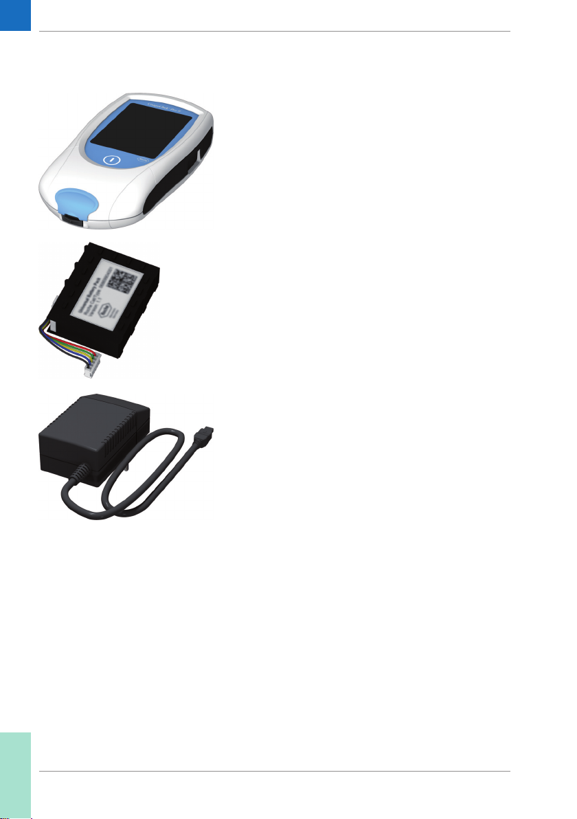
Contents of the pack The CoaguChek Pro II pack contains the following items:
■ CoaguChek Pro II meter
■ Universal Battery Pack
■ Power supply
■ Operator’s Manual (printed version, not shown
here)
■ Manual CD ROM (contains PDF files of the Opera-
tor’s Manual in other languages, not shown here)
Check for completeness and transport damage immediately after unpacking.
Page 15
1.2 Important safety instructions and additional information
This section explains how safety-related messages and
information related to the proper handling of the system
are presented in the CoaguChek Pro II Operator’s
Manual. Read these passages carefully.
The safety alert symbol alone (without a signal word)
promotes awareness to hazards which are generic or
directs the reader to related safety information.
These symbols and signal words are used for specific
hazards:
WARNING
Indicates a hazardous situation which, if not avoided,
WARNING
CAUTION
could result in death or serious injury.
CAUTION
Indicates a hazardous situation which, if not avoided,
could result in minor or moderate injury.
15
NOTICE
NOTICE
Indicates a hazardous situation which, if not avoided,
may result in damage to the system.
Important information that is not safety relevant is presented against a colored background (without a symbol). Here you will find additional information on correct
use of the meter or useful tips.
Introduction • 1
Page 16
16
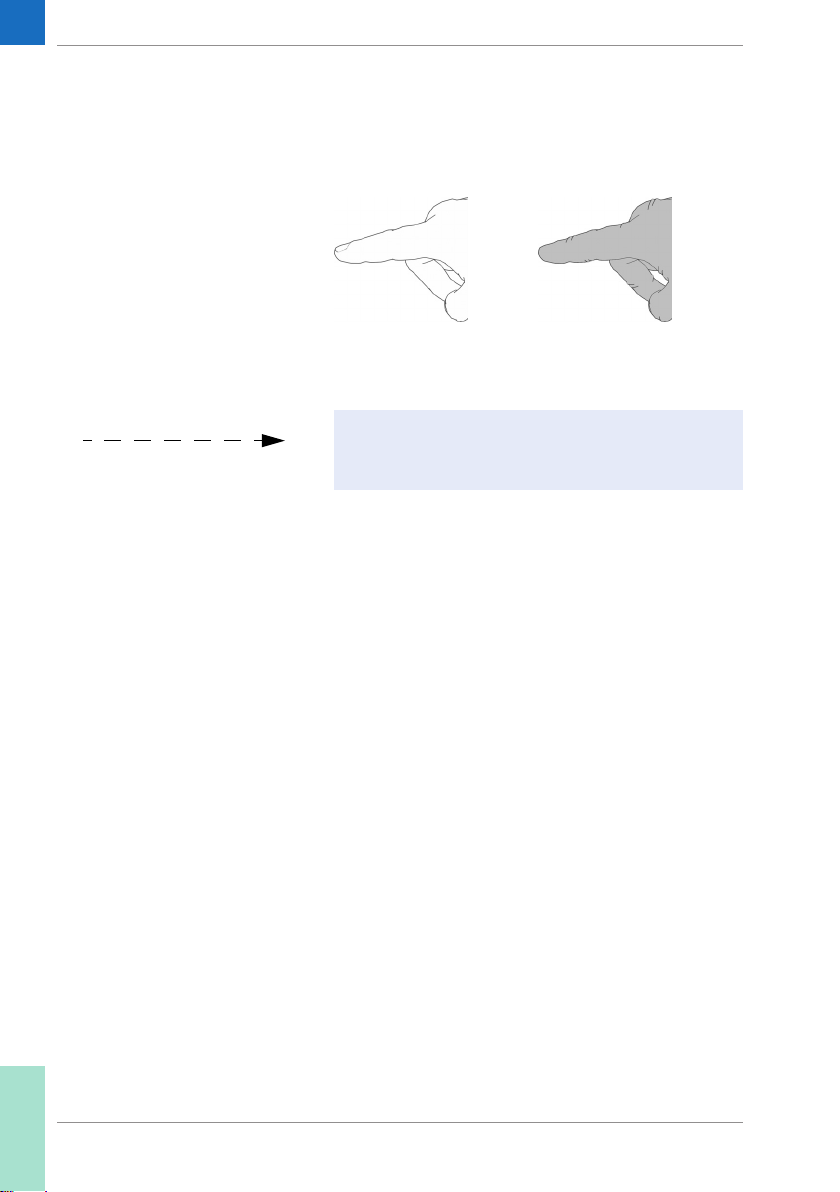
Illustrations in this manual show two different kinds of
hands:
Hand without glove Hand with glove
A dashed arrow between screen illustrations indicates
that some screens have been skipped in these
illustrations.
Page 17
Safety information
WARNING
17
Operator qualification
Only trained healthcare professionals may operate the
CoaguChek Pro II system. Operators must have received
comprehensive instruction in the operation, quality control, and care of the CoaguChek Pro II system.
Protection against infection
There is a potential risk of infection. Healthcare professionals using the CoaguChek Pro II system must be
aware that any object coming into contact with human
blood is a potential source of infection. Healthcare
professionals must also be aware that any cross-contamination is a potential source of infection for patients.
■ Use gloves.
■ Use an auto-disabling single-use lancing device for
each patient.
■ Dispose of used lancets and needles in a sturdy
sharps container with lid.
■ Dispose of used test strips according to your institu-
tion’s infection control policy.
■ Follow all health and safety regulations in force
locally.
WARNING
Avoidance of electrical shock, fire, and explosions
■ Only use Roche Diagnostics original accessories
(cables, power supply units, battery packs, and spare
parts). Third-party cables, power supply units, and
battery packs can cause the battery pack to explode
or the meter to become damaged.
■ Do not use loose power sockets or damaged power
supply units, cables, plugs, or battery packs.
■ Do not short circuit the power supply unit, the
Handheld Base Unit contacts, or the battery pack.
■ Do not drop the CoaguChek Pro II meter, the power
supply unit, or the battery pack and protect these
against shaking and vibrations.
Introduction • 1
Page 18

18
Disposal of the system
General care
WARNING
Infection by a potentially biohazardous instrument
The CoaguChek Pro II system or its components must be
treated as potentially biohazardous waste. Decontamination (i.e., a combination of processes including cleaning,
disinfection and/or sterilization) is required before reuse,
recycling, or disposal.
Dispose of the system or its components according to
the appropriate local regulations. Always remove the
battery pack before thermal disinfection.
NOTICE
Clean the meter only with the solutions recommended
(see page 147). Using other solutions may result in
incorrect operation and possible system failure. Do not
let cleaning solution enter the instrument. Make sure
that the meter is thoroughly dried after cleaning or
disinfecting.
Battery pack The meter contains a rechargeable battery pack that
begins charging as soon as the power adapter is connected or the meter is placed on an active Handheld Base
Unit (i.e., one connected to a power supply).
NOTICE
Use only the specially designed battery pack provided by
Roche Diagnostics. Using any other type of battery may
damage the system.
Page 19

WARNING
19
Possible hazards posed by the battery pack
Damaged or swollen battery packs can overheat, catch
fire, or leak. Immediately cease use of CoaguChek Pro II
meters with damaged or swollen battery packs and
under no circumstances recharge them (do not place in
the Handheld Base Unit).
Overheating can cause the battery pack to catch fire or
explode.
■ Never throw the battery pack or the meters onto a
fire. Do not dismantle, compress, or pierce the
battery pack as this could cause an internal short
circuit that leads to overheating.
■ Do not place either the battery pack or the
CoaguChek Pro II meter on or in heating appliances, such as a microwave, conventional oven, or
radiator.
■ Avoid prolonged exposure to direct sunlight, e.g.,
when the meter is docked in the Handheld Base
Unit. Keep this in mind when positioning the Handheld Base Unit.
Battery fluid or materials leaking from damaged battery
packs can irritate your skin or cause burns due to high
temperatures.
■ Avoid contact with leaking battery fluid. In the
event of accidental contact with the skin, rinse with
water. If you get battery fluid in your eye(s), you
should also seek medical attention.
Handle and dispose of battery packs with care.
Extreme temperatures reduce the charging capacity
and usage period of the meter and the battery pack.
Introduction • 1
Page 20
20
Observe the following general safety instructions for
handling the battery pack:
Disposal of used battery packs
Do not dispose of the battery pack with normal domestic
waste. Dispose of used battery packs in accordance with
applicable local regulations and directives and your
facility’s guidelines on the disposal of electronic waste
equipment.
■ When storing or disposing of the battery pack, use
the manufacturer's original packaging.
Save or download data from the meter prior to replacing
the battery pack to prevent loss of data (see Chapter 7).
■ Always power the meter off before removing the
battery pack.
■ When the Battery Low warning is displayed, the
meter must be returned as soon as possible to
the Handheld Base Unit or connected to the power
adapter for recharging.
■ When the battery capacity is too low for further
tests, the meter must be returned immediately to
the Handheld Base Unit or connected to the power
adapter for recharging.
Electromagnetic Interference The meter fulfills the IEC 61326-2-6 requirements for
emitted interference and interference immunity.
Do not use the meter near strong electromagnetic fields,
which could interfere with the proper operation of the
meter.
Electrostatic discharges may cause malfunction of the
meter.
Page 21

Touchscreen
21
NOTICE
Local Area Network: protection from unauthorized access
Use only your finger (even when wearing gloves) or
■
special pens designed for use with touchscreens to
touch the screen elements. Using pointed or sharpedged objects can damage the touchscreen.
■ Avoid prolonged exposure to direct sunlight. Direct
sunlight may reduce the life expectancy and functionality of the display.
■ If this meter is connected to a local area network,
this network must be protected against unauthorized access. In particular, it must not be linked
directly to any other network or the Internet. Customers are responsible for the security of their local
area network, especially in protecting it against
malicious software and attacks. This protection
might include measures, such as a firewall, to separate the device from uncontrolled networks as well
as measures that ensure that the connected network is free of malicious code.
■ If you use a customized data management system
solution, ensure that sensitive data transmitted via
the POCT1-A interface is protected by appropriate
security measures.
■ Ensure that the instrument is protected against
unauthorized physical access and theft.
■ Do not use shared user or operator accounts on
meter, DMS and network.
■ Whether working in a wired or wireless environ-
ment, use a strong password for user or operator
accounts on the meter, DMS, and network. Observe
your own facility guidelines on password management where available, or apply the rules for strong
passwords, see “Characteristics of strong passwords” below.
Introduction • 1
Page 22

22
Wired network connection If the Handheld Base Unit from Roche Diagnostics is
used to connect this meter to a local area network, the
Handheld Base Unit must be protected against unauthorized access by means of a strong password manage-
ment. Observe your own facility guidelines on password
management where available, or apply the following
rules:
Characteristics of strong passwords
■ Passwords should not contain the user’s account
name or parts of the user’s full name that exceed
two consecutive characters.
■ Passwords should be at least eight characters in
length.
■ Passwords should contain characters from the
following three categories:
– English uppercase alphabetic characters
(A through Z)
– English lowercase alphabetic characters
(a through z)
– Numeric characters (0 through 9)
Examples of weak passwords
■ uhxwze11 contains no upper case letter.
■ UHXW13SF contains no lower case letter.
■ uxxxxx7F contains the same character more than
four times.
■ x12useridF contains a substring of the user ID
longer than four characters.
Page 23

Wireless connectivity If the meter is equipped with WLAN functionality:
Wireless connectivity allows the meter to send data (test
results, patient IDs, operator IDs, etc.) to the data management system without the need to return the meter to
the Handheld Base Unit. This feature must be configured
by the system administrator. Observe the guidelines of
your facility for using wireless local area network connections. For a description of the CoaguChek Pro II meter’s
ability to connect to Wireless Local Area Networks
(WLAN, Wi-Fi), see appendix C.1.
Radiofrequency radiation exposure information
Glossary:
■ “FCC” stands for “Federal Communications
Commission” (USA).
■ “RF” stands for “radio frequency”
■ “RSS” stands for “Radio Standards Specification”
(Canada).
■ “WLAN” stands for “Wireless Local Area
Network”
23
Introduction • 1
Page 24

24
The Industrial, Scientific and Medical (ISM) radio
frequencies may contain emissions from microwave
ovens, heaters, and other noncommunication devices.
While these types of devices usually pose no threat of
interference as they are low-powered devices, the possibility exists that some industrial high power systems may
wipe out any attempted communication use of a WLAN.
Therefore, perform a site survey and interference analysis
with a spectrum analyzer to view the entire spectrum,
looking for signals that might not only be within the frequency range of the intended WLAN but also could be
near or at the same frequency and cause interference.
Roche Diagnostics supports industry wireless standards
and recommends using products that have Wi-Fi certification. This certification tests products to the 802.11 industry
standards for basic connectivity, security, authentication,
Quality of Service (QoS), interoperability and reliability. The
Wi-Fi CERTIFIED logo is an assurance that the Wi-Fi Alliance has tested a product in numerous configurations and
with a diverse sampling of other devices to ensure compatibility with other Wi-Fi CERTIFIED equipment that operates
in the same frequency band. The Wi-Fi Alliance network of
independent test labs conducts interoperability testing
programs to ensure that wireless devices work together
and support secure connections.
Page 25

The CoaguChek Pro II system complies with FCC radiation exposure limits set forth for an uncontrolled environment. This equipment should be installed and operated
with minimum distance of 20 cm (8 inches) between the
radiator and your body.
This transmitter must not be co-located or operated in
conjunction with any other antenna or transmitter.
Changes or modifications made to this equipment not
expressly approved by Roche Diagnostics may void the
FCC authorization to operate this equipment.
This device complies with Part 15 of the FCC Rules and
with RSS-210 of Industry Canada. Operation is subject to
the following two conditions:
(1) this device may not cause harmful interference,
and
(2) this device must accept any interference received,
including interference that may cause undesired operation.
25
Introduction • 1
Page 26

26
The CoaguChek Pro II system complies with the emission
and immunity requirements described in EN 61326-2-6. It
has been designed and tested to CISPR 11 Class B.
This equipment has been tested and found to comply
with the limits for a Class B digital device, pursuant to
Part 15 of the FCC Rules. These limits are designed to
provide reasonable protection against harmful interference in a residential installation. This equipment generates, uses and can radiate radio frequency energy and, if
not installed and used in accordance with the instructions, may cause harmful interference to radio communications. However, there is no guarantee that interference
will not occur in a particular installation. If this equipment
does cause harmful interference to radio or television
reception, which can be determined by powering the
equipment off and on, the user is encouraged to try to
correct the interference by one or more of the following
measures:
■ Reorient or relocate the receiving antenna.
■ Increase the separation between the equipment
and receiver.
■ Connect the equipment into an outlet on a circuit
different from that to which the receiver is connected.
■ Consult the dealer or an experienced radio/TV
technician for help.
This Class B digital apparatus complies with Canadian
ICES-003.
Page 27

Operating conditions To ensure that the meter functions properly, please
observe the following guidelines:
■ Only use the meter at a room temperature between
12 °C and 32 °C (54 °F and 90 °F).
■ Only use the meter at a relative humidity between
10% and 85% (no condensation).
■ When operating the meter using the power adapter,
use only a voltage of 100 V to 240 V (± 10%) , 50/
60 Hz.
■ When testing, place the meter on a level, vibration-
free surface, or hold it so it is roughly horizontal.
Quality control The meter has a number of built-in quality-control
functions:
■ A check of the electronic components and func-
tions every time the meter is powered on.
■ A check of the test strip temperature while a test is
in progress.
■ A check of the expiration date and lot information
on the test strip based on the code chip data.
■ An onboard quality control within every single test
strip.
Roche Diagnostics offers liquid quality controls for the
CoaguChek Pro II system. These controls are designed to
assist you in meeting regulatory compliance requirements at your facility.
27
Introduction • 1
Page 28
28
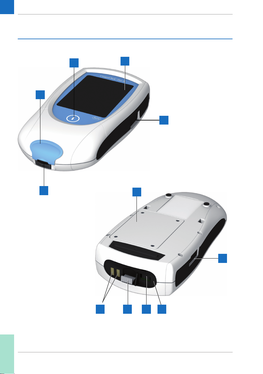
1.3 Overview of the meter elements
B
C
D
A
E
F
H IG J
E
Page 29

29
A Touchscreen
Shows test results, information, icons,
and results recalled from memory. To
select an option, simply touch the
button lightly.
B On/Off button
Press this button to power the meter on
or off.
C Test strip guide cover
Remove this cover to clean the test strip
guide (if it has become soiled, e.g., with
blood).
D Test strip guide
Insert the test strip here.
E Barcode scanner
The integrated barcode scanner can
scan operator, patient, and QC sample
IDs into the meter.
F Battery compartment cover
Remove to insert the battery pack.
G Charging terminals
Used for power supply and/or charging
the battery pack when the meter is
docked in the (optional) Handheld Base
Unit.
H Code chip slot (shown with code chip)
Insert the code chip here.
I Connection socket for power
adapter
Plug in the power adapter here.
J Infrared interface
(Covered by the semi-transparent
panel) Supports data communication.
Introduction • 1
Page 30
30
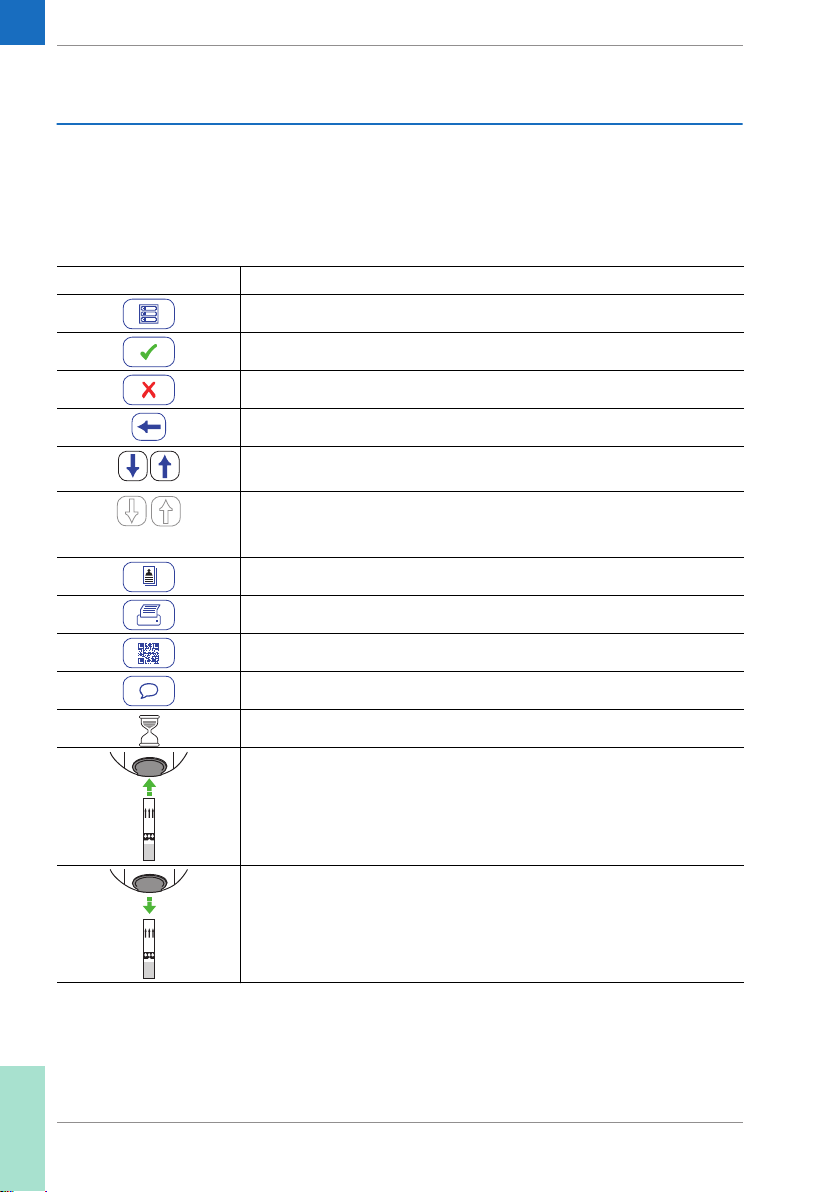
1.4 Buttons and icons overview
Button/Icon Meaning
Go to Main Menu
OK; save setting
Cancel; discard setting
Return (to previous menu)
Decrease/increase the value displayed.
Scroll through lists that are too long to be displayed all at once.
Inactive button:
Value cannot be further decreased/increased or:
End of list in this direction is reached
List of tests of a specific patient
The buttons and icons that appear during normal operation are shown here, along with their respective meanings. Error messages and the description of the icons
linked to them are provided in a separate chapter. See
“Troubleshooting” starting on page 155.
Print after test result or from memory
Display test result as QR code
Add a comment
Operator must wait until the meter has completed an action
Insert test strip
Remove test strip
Page 31

Button/Icon Meaning
Apply sample (the time left to apply sample is counted down in the
display)
Apply liquid control (QC) sample (the time left to apply sample is
counted down in the display)
Insert the test strip code chip
31
QC
%Q
SEC
INR
QC
Insert the QC code chip
Automatic quality control completed successfully
Results are displayed as a Quick percentage value
Results are displayed in seconds
Results are displayed in INR units
Result in the chosen unit of measure is above the measuring range.
Result in the chosen unit of measure is below the measuring range.
Quality control: Result is above the specified range
Quality control: Result is below the specified range
Battery status:
■ When the battery pack is fully charged, all segments are lit.
■ Individual segments disappear one by one as the battery pack
becomes weaker.
■ When there is only one segment remaining the icon is displayed
in red.
■ When there is no segment remaining, you may not be able to finish
performing a test. Recharge as soon as possible.
Operation with power supply adapter
am
pm
Time between midnight and noon (in 12-hour time format)
Time between noon and midnight (in 12-hour time format)
Introduction • 1
Page 32

32
Button/Icon Meaning
Room or meter temperature is outside the acceptable range
The test strip guide cover is open
Reports a status message (see: Chapter 9, Troubleshooting)
Reports an error message or a warning (see: Chapter 9, Troubleshooting)
QC!
Button/Icon Meaning
Lockout, one or more parameters are locked
Communication is taking place via the infrared interface
■ If displayed in the status bar: communication is taking place via
WLAN
■ If displayed on the Patient Test button: connectivity lockout, only
STAT testing possible
An OTS request is pending
Cleaning/Disinfection necessary
Patient test result is out of normal patient test range
The following icons may appear when using the meter in
conjunction with a data management system (DMS).
Page 33

1.5 Power supply
33
The CoaguChek Pro II meter is operated with the
rechargeable battery pack. Insert the battery pack even
when using the power adapter. This ensures that you will
not lose the date and time settings if the power goes out.
The power adapter also serves as a charger for the
battery pack.
To save power, the CoaguChek Pro II meter has an automatic power-off function (auto-off). The default setting is
5 minutes of inactivity (e.g., no screen touches). It is
possible to customize the auto-off function via your Setup
selection (refer to “Auto Off” on page 62).
When the meter powers itself off, all results are automatically saved to memory.
Introduction • 1
Page 34

34
Main Menu
Review Results
05/29/2015
Patient T
Control Test
est
Setup
09:15 am
During battery operation, the meter always displays the
battery power level.
When replacing the battery pack, insert the new
battery pack within 24 hours of removing the old one.
Otherwise you may need to re-enter date and time.
The meter retains results in memory even when no battery pack is inserted. All settings other than date and time
are retained as well.
Dispose of used battery packs in an environmentally
responsible manner in accordance with applicable local
regulations and directives. See “Infection by a potentially
biohazardous instrument” on page 18.
Page 35

2 Putting the Meter into Operation
Before using the meter for the first time, perform the following steps:
1 Install the battery pack
2 Connect the power adapter to charge the battery
pack
3 Set the current date and time
4 Enter your chosen settings (language, unit of
measure, user administration if applicable, etc.)
35
Putting the Meter into Operation • 2
Page 36

36
2.1 Installing or replacing the battery pack
When shipped, the battery pack is not installed in the
CoaguChek Pro II meter.
Unused battery packs lose their charge over time and
have to be recharged before they can be used. After
installing a new battery pack, the meter should be
charged for two hours before testing. Please note that
the battery pack will only reach full capacity once it has
been fully emptied and charged several times.
Whenever the meter is placed on an active Handheld
Base Unit or powered by the power adapter, the
icon is displayed. This icon shows that power is available and the meter can be charged if necessary.
Make sure that the permitted temperature range for
charging the battery pack (12-32 °C or 54-90 °F) is
maintained during installation and initial setup.
Page 37

Removing the battery pack 1 If a battery pack is already installed, make sure that
the meter is powered off.
2 Place the meter face down on a level surface.
37
3 Using a an appropriate starshaped screwdriver, e.g.
®
size T5, remove the four screws holding the
Torx
battery compartment cover in place.
4 Remove the battery compartment cover from the
meter. The battery pack now visible is connected to
the meter by a plug.
5 Carefully lift the battery pack and remove the plug
connector.
Disposal of used battery packs
Do not dispose of the battery pack with normal domestic
waste. Dispose of used battery packs in accordance with
applicable local regulations and directives and your
facility’s guidelines on the disposal of electronic waste
equipment.
Putting the Meter into Operation • 2
Page 38

38
Installing the battery pack 1 Loosen the screws on the battery compartment cover
until they are protruding about 4-5 mm (2/10 in).
2 Hold the battery pack in your hand, with the wires
and the plug pinched between your thumb and
index finger.
3 Plug the connector plug into the socket.
4 Place the battery pack inside the battery compart-
ment as shown above.
To position the battery pack correctly, always align the
ridges on the side of the battery pack with the ridges on
the inside of the battery compartment.
Page 39

5 Place the cover on the battery compartment. Make
sure that
– the plug connector wires do not get pinched
between meter and cover
– the protrusion on the battery compartment cover
fits into the corresponding groove on the battery
compartment rim
6 Tighten all four screws until snug (do not over-
tighten).
39
Putting the Meter into Operation • 2
Page 40

40
Year:
Date
2015
09:15 am
After inserting a new battery pack, the meter powers on
automatically.
■ The Roche logo is displayed. If the meter does not
power on automatically, the battery pack may be
empty. Connect the power adapter for a minimum
of 30 minutes, then remove the plug and try to
power the meter on. If it powers on, the battery
pack is charging properly.
Month:
Day:
05/29/2015
5
Time
29
Hour:
Minute:
05/29/2015
9
59
AM PM
09:15 am
■ Within a short period of time, the start screen
should appear.
■ If the meter has been without power for too long, it
will show the date and time settings dialog and you
have to re-enter the date and time settings.
■ The screens for entering the date and the time
appear.
7 Enter the date and time. After you have entered the
correct information, confirm each screen with .
After installing a new battery pack, the meter should be
charged for two hours before testing.
Page 41

2.2 Powering the meter on and off
1 Place the meter on a level, vibration-free surface, or
2 Power the meter on by pressing the button.
You can also power on the meter directly by inserting a
test strip, connecting the power adapter, or by docking
it in the Handheld Base Unit.
3 To power the meter off after use, press the
Checking the software version
41
hold it in your hand so it is roughly horizontal.
button for approximately 1 second.
Init
CoaguChek
04.00.00
After displaying the Roche logo, the meter briefly displays
the Init (for “initialization”) screen. Here you can check
®
which software version is currently running on your
meter. (The Init screen shown here is for illustration purposes only. Version numbers on your meter may differ.)
Putting the Meter into Operation • 2
Page 42

42
This page intentionally left blank.
Page 43

3 Meter Setup
43
Note on presentation of screen elements in this manual
Buttons are screen prompts that cause something to
happen when touched. The names of all buttons are
either shown as bold text or as the icon used on the
button (e.g., for OK).
Other screen elements (e.g., Menu titles) are written in
italics. These screen elements are not active.
If you have not set the date and time (after powering on
for the first time or because the battery pack was
removed from the meter for more than 10 minutes), you
cannot perform a test. In that case powering on the
meter takes you immediately to the Setup mode, where
you must set the date and time (see page 53 and following).
After date and time have been set, the meter automatically moves to the Main Menu, where you can start a
test or enter more settings.
You can open any displayed function by touching (or tapping) the button for it with your finger (or a special pen
for this purpose). “Tap” means: Touch the button, then
remove your finger from the touchscreen. The next
screen appears once you remove your finger.
If the meter did not automatically enter the Setup mode
(e.g., after the battery pack was replaced), you can open
the Setup Menu from the Main Menu.
Meter Setup • 3
Page 44

44
Main Menu
05/29/2015
Patient T
est
Control Test
Review Results
Setup
09:15 am
05/29/2015
Setup Menu
Screen
Options
ID Setup
QC Settings
Diagnostics
1 Touch Setup to open the meter settings.
2 Select the relevant group of settings (see the
Settings summary following this section.).
09:15 am
Page 45

3.1 Settings summary
Setup
Screen
45
The diagram below shows all of the setup areas that can
be accessed on the meter.
Options
ID Setup
QC Settings
Diagnostics
Contrast
Sort
Admin.
QC Range
Result Units
Beeper
Result
Confi rmation
Auto Off
Operator
Lockouts
Language
Selection
Connection
Date / Time
Parameter
Selection
Patient
Scan QC
Material
General Hardware
Software
Memory
Usage
Wireless Setup
Meter Setup • 3
Page 46

46
Group Subgroup Setting Values *
Screen
Contrast 0 – 10 (5 *)
Result Units INR *
Result Confirmation Enable
Language Selection Dansk
Date/Time Date 01/01/2015 *
Time 12:00 am *
Date formats DD.MM.YYYY (01.01.2015)
Time formats 24-hour time format (24h)
INR/SEC
INR/%Q
Disable *
Deutsch
English *
Español
Français
Italiano
Nederlands
Norsk
Português
Suomi
Svenska
MM/DD/YYYY (01/01/2015) *
YYYY-MM-DD (2015-01-01)
12-hour time format (12h), with
am/pm *
* Default settings are labeled with an asterisk (*).
Page 47

Group Subgroup Setting Values *
Options
ID Setup
Sort Date/Time *
Patient ID
Patient Name
Beeper
Auto Off [minutes] Off
Connection
Parameter Selection Enable
Admin. (Administrator) Blank (Off) *
Operator (Operator List is optional) Inactive *
Patient No *
Beeper Off
Low
Medium *
High
Key Click Off *
On
1 … (5*) … 10
15
20
25
30
40
50
60
Off *
Computer
Printer
QR Code Off *
On
Disable *
Active
Optional
Required
47
* Default settings are labeled with an asterisk (*).
Meter Setup • 3
Page 48

48
Group Subgroup Setting Values *
QC Settings
Diagnostics
QC Range PT Default Range*
aPTT
Lockouts
Scan QC Material Optional *
General
Software
Hardware
Memory Usage
Wireless Setup
Operator Lockout
(only if the Operator
option is set to Active
and an operator list is
available)
QC Lockout New code (Yes/No)
STAT Test Config. Enable
Custom Range
Off *
Weekly
Monthly
Every 3 months
Every 6 months
Yearly
Number of levels
Scheduled
– No*
– Daily
– Weekly
– Monthly
Number of hours
Number of strips
For each option except “No”:
– Number of levels (1/2)
Disable *
Quantity
Scan Only
* Default settings are labeled with an asterisk (*).
Page 49

3.2 Screen setup
The Screen setup area contains the options for changing
the display.
Contrast Use the Contrast menu to adjust the display to your ambi-
ent light conditions and make it easier to read.
Main Menu
Patient T
Control Test
Review Results
Setup
est
09:15 am
Setup Menu
Screen
Options
ID Setup
QC Settings
Diagnostics
09:15 am
Screen
Result Confi rmation
Language Selection
09:15 am
Contrast
Result Units
Date / Time
49
05/29/2015
Contrast
Contrast (0-10):
05/29/2015
05/29/2015
05/29/2015
1 From the Main Menu, touch Setup to open the
meter settings.
2 From the Setup Menu, touch Screen.
3 From the Screen menu, touch Contrast.
If a button is grayed out, this means the function is not
available.
09:15 am
4 Touch or to change the contrast in a range
from 0 to 10.
■ Contrast “0” makes the display very dark.
5
■ Contrast “10” makes the display very light.
5 Touch to save this setting, or touch to exit
this menu without saving any changes. The display
automatically returns to the previous screen.
Meter Setup • 3
Page 50

50
Result Units Use this setting to select the unit(s) in which the result is
displayed. This setting only applies to PT test results.
Regardless of the settings chosen for PT, aPTT is always
displayed in seconds.
Main Menu
Patient T
Control Test
Review Results
Setup
est
09:15 am
Setup Menu
Screen
Options
ID Setup
QC Settings
Diagnostics
09:15 am
Screen
Contrast
Result Units
Result Confi rmation
Language Selection
Date / Time
09:15 am
05/29/2015
Units
05/29/2015
INR
INR/SEC
INR/%Q
09:15 am
05/29/2015
05/29/2015
1 From the Main Menu, touch Setup to open the
meter settings.
2 From the Setup Menu, touch Screen.
3 From the Screen menu, touch Result Units.
The current unit of measure setting is highlighted (white
type on a blue background). You can select either:
■ INR
■ INR and seconds
■ INR and Quick value in %
4 Touch the button to select the unit of measure of
choice. Your selection is now highlighted.
5 Touch to save this setting, or touch to exit
this menu without saving any changes. The display
automatically returns to the previous screen.
Page 51

Result Confirmation In some circumstances, it may be useful for operators to
confirm the validity of their results. Use this setting to
prompt operators to confirm the results of every test.
Main Menu
Patient T
Control Test
Review Results
Setup
est
09:15 am
Setup Menu
Screen
Options
ID Setup
QC Settings
Diagnostics
09:15 am
Screen
Result Confi rmation
Language Selection
09:15 am
Contrast
Result Units
Date / Time
51
05/29/2015
Result Confi rmation
Enable
Disable
05/29/2015
09:15 am
05/29/2015
05/29/2015
1 From the Main Menu, touch Setup to open the
meter settings.
2 From the Setup Menu, touch Screen.
3 From the Screen menu, touch Result
Confirmation.
4 Touch Enable or Disable. Your selection is now
highlighted.
5 Touch to save this setting, or touch to exit
this menu without saving any changes. The display
automatically returns to the previous screen.
Meter Setup • 3
Page 52

52
Language Selection Use this setting to select the meter language.
Main Menu
Patient T
Control Test
Review Results
Setup
est
09:15 am
Setup Menu
09:15 am
Screen
Options
ID Setup
QC Settings
Diagnostics
Screen
Contrast
Result Units
Result Confi rmation
Language Selection
Date / Time
09:15 am
05/29/2015
05/29/2015
05/29/2015
1 From the Main Menu, touch Setup to open the
meter settings.
2 From the Setup Menu, touch Screen.
3 From the Screen menu, touch Language
Selection.
The current language setting is highlighted (white type
on a blue background). You can select either:
■ Dansk
■ Deutsch
■ English
■ Español
■ Français
■ Italiano
■ Nederlands
■ Norsk
■ Português
■ Suomi
■ Svenska
Page 53

53
Language
Dansk
Deutsch
English
Español
Français
09:15 am
4 Touch or to display the language of choice
on the screen.
If the arrow is just an outline , you have reached
the end of the list in the repective direction.
5 Touch the button to select the language of choice.
Your selection is now highlighted.
6 Touch to save this setting, or touch to exit
05/29/2015
this menu without saving any changes. The display
automatically returns to the previous screen.
Setting the date When you power on the meter for the first time (or after a
long period without power), the input field for the date
automatically appears first. The date (and time) must be
entered before the meter can be used further. If at a later
time a date adjustment is needed, go to the Setup Menu,
then select the menu of choice.
Both Date and Time display formats are controlled by
the Format options you select (see page 56). Options
shown in the Date and Time menus may vary depending
on the chosen formats. You can choose between the
following display formats:
■ Date: Day.Month.Year, e.g., 29.05.2015
■ Date: Month/Day/Year, e.g., 05/29/2015
■ Date: Year-Month-Day, e.g., 2015-05-29
■ Time: 24H or 12H
Meter Setup • 3
Page 54

54
Main Menu
05/29/2015
Date/Time
05/29/2015
Patient T
est
Control Test
Review Results
Setup
Set Date
Set Time
Format
09:15 am
09:15 am
Year:
Month:
Day:
Date
2015
29
Setup Menu
05/29/2015
Screen
Options
ID Setup
QC Settings
Diagnostics
09:15 am
Screen
Result Confi rmation
Language Selection
05/29/2015
09:15 am
Contrast
Result Units
Date / Time
1 From the Main Menu, touch Setup to open the
meter settings.
2 From the Setup Menu, touch Screen.
3 From the Screen menu, touch Date/Time.
4 From the Date/Time menu, touch Set Date.
5 Touch and to set the year, then the month,
then the day.
6 Touch to save this setting, or touch to exit
this menu without saving any changes. The display
09:15 am
automatically returns to the previous screen.
If this setup menu appeared automatically after powering
the meter on, you must touch to complete the first
5
date setting.
7 Touch to return to the Screen menu.
05/29/2015
Page 55

Setting the time When you power on the meter for the first time (or after a
long period without power), this Time setup menu
appears automatically after you set the date. If at a later
time a time adjustment is needed, go to the Setup Menu,
then select the menu of choice.
Main Menu
Patient T
Control Test
Review Results
Setup
est
09:15 am
Setup Menu
Screen
Options
ID Setup
QC Settings
Diagnostics
09:15 am
Screen
Result Confi rmation
Language Selection
09:15 am
Contrast
Result Units
Date / Time
55
05/29/2015
Date/Time
05/29/2015
Set Date
Set Time
Format
09:15 am
Hour:
Minute:
05/29/2015
Time
9
59
AM PM
09:15 am
05/29/2015
05/29/2015
1 From the Main Menu, touch Setup to open the
meter settings.
2 From the Setup Menu, touch Screen.
3 From the Screen menu, touch Date/Time.
4 From the Date/Time menu, touch Set Time.
5 Touch and to set the hours, then the min-
utes.
6 Touch to save this setting, or touch to exit
this menu without saving any changes. The display
automatically returns to the previous screen.
If this setup menu appeared automatically after powering
the meter on, you must touch to complete the first
time setting.
7 Touch to return to the Screen menu.
Meter Setup • 3
Page 56

56
Setting the display options for date and time
Patient T
Control Test
Setup
09:15 am
est
Main Menu
Review Results
05/29/2015
Select your preferred format for the date and time display.
Setup Menu
05/29/2015
Screen
Options
ID Setup
QC Settings
Diagnostics
09:15 am
Screen
Result Confi rmation
Language Selection
05/29/2015
09:15 am
Contrast
Result Units
Date / Time
1 From the Main Menu, touch Setup to open the
meter settings.
2 From the Setup Menu, touch Screen.
3 From the Screen menu, touch Date/Time.
4 From the Date/Time menu screen, touch Format.
The current settings are highlighted. You can select one
of the following display formats:
■ Date: DD.MM.YYYY (Day.Month.Year),
e.g., 29.05.2015
■ Date: MM/DD/YYYY (Month/Day/Year),
e.g., 05/29/2015
■ Date: YYYY-MM-DD (Year-Month-Day),
e.g., 2015-05-29
■ Time: 24H or 12H
Page 57

57
Date/Time
05/29/2015
Set Date
Set Time
Format
09:15 am
Date:
Time:
05/29/2015
Format
DD.MM.YYYY
MM/DD/YYYY
YYYY-MM-DD
09:15 am
24H 12H
5 Touch the button with the display format of choice
for date and time. Your selection is now highlighted.
6 Touch to save this setting, or touch to exit
this menu without saving any changes. The display
automatically returns to the previous screen.
7 Touch to return to the Screen menu.
Meter Setup • 3
Page 58

58
3.3 Options setup
Sort Sort refers to the order in which measured and stored
results are displayed when you use the Review Results
function of the CoaguChek Pro II meter. You can display
stored results chronologically by date and time or by person, based on the Patient ID.
Main Menu
Patient T
Control Test
Review Results
Setup
est
09:15 am
Setup Menu
Screen
Options
ID Setup
QC Settings
Diagnostics
09:15 am
Options
Parameter Selection
Sor
t
Beeper
Auto Off
Connection
09:15 am
05/29/2015
05/29/2015
05/29/2015
1 From the Main Menu, touch Setup to open the
meter settings.
2 From the Setup Menu, touch Options.
3 From the Options menu, touch Sort.
Page 59

Sort By:
Sort
Date / Time
Patient ID
Patient Name
09:15 am
59
The current setting is highlighted. You may select from
the following sort options:
■ By Date/Time
■ By Patient ID
■ By Patient Name
4 Touch the button to select the Sort by option of
choice. Your selection is now highlighted.
The sort option Patient Name is available only when
used together with a patient list. Patient lists can only be
created with a DMS. For more details see “Data handling”, starting on page 139.
05/29/2015
5 Touch to save this setting, or touch to exit
this menu without saving any changes. The display
automatically returns to the previous screen.
Meter Setup • 3
Page 60

60
Beeper The CoaguChek Pro II meter can display information visu-
ally and alert you to special circumstances with a Beeper.
The meter always beeps when it is switched on. When the
Beeper function is enabled the meter beeps once when:
■ it detects a test strip
■ pre-heating of the test strip is complete and you
need to apply a sample
■ it detects a sample
■ the test is completed and the results are displayed
(a long beep)
■ an error occurs (three short beeps)
■ an external power adapter is connected when the
meter is on
■ the meter is docked
■ a barcode is scanned
We recommend that you keep the Beeper enabled at all
times.
You can also activate a Key Click. When a Key Click is
enabled, the meter clicks briefly every time a button is
touched, facilitating the input of information.
Page 61

61
Main Menu
05/29/2015
Beeper
Key Click:
05/29/2015
Patient T
est
Control Test
Review Results
Setup
Off
Low
Medium
High
On Off
09:15 am
09:15 am
Sor
t
Beeper
Auto Off
Connection
09:15 am
Setup Menu
05/29/2015
Screen
Options
ID Setup
QC Settings
Diagnostics
09:15 am
Options
Parameter Selection
05/29/2015
1 From the Main Menu, touch Setup to open the
meter settings..
2 From the Setup Menu, touch Options.
3 From the Options menu, touch Beeper.
The current setting is highlighted. You may select from
the following options:
For the Beeper
■ Off
■ Low
■ Medium
■ High
For the Key Click
■ On
■ Off
4 Touch the button with the desired setting for the
Beeper, then touch the button with the setting of
choice for the Key Click. Both selections are now
highlighted.
5 Touch to save this setting, or touch to exit
this menu without saving any changes. The display
automatically returns to the previous screen.
Meter Setup • 3
Page 62

62
Auto Off You can set up your CoaguChek Pro II meter so that it
powers itself off automatically if it has not been used (no
buttons touched or tests run) for a preselected time
period. Use this feature to save power and extend the life
of the battery pack.
Main Menu
Patient T
Control Test
Review Results
Setup
est
09:15 am
Setup Menu
Screen
Options
ID Setup
QC Settings
Diagnostics
09:15 am
Options
Parameter Selection
Sor
t
Beeper
Auto Off
Connection
09:15 am
05/29/2015
05/29/2015
05/29/2015
1 From the Main Menu, touch Setup to open the
meter settings.
2 From the Setup Menu, touch Options.
3 From the Options menu, touch Auto Off.
If the meter is connected to the power adapter or the
Handheld Base Unit, the Auto Off function has a different effect:
The meter powers itself off after 10 minutes without
user interaction, regardless of the selected settings
Page 63

63
Minutes:
Auto Off
09:15 am
You may select from the following options:
■ Off (meter never powers itself off)
5
■ Time until meter powers itself off:
1…10, 15, 20, 25, 30, 40, 50, 60 minutes
4 Touch or to select the time of choice in min-
utes or to switch the feature off.
05/29/2015
5 Touch to save this setting, or touch to exit
this menu without saving any changes. The display
automatically returns to the previous screen.
Connection In the Connection menu you can configure the data
exchange with external devices. The meter can be connected either to a computer (DMS) or a printer. In addition to this direct data output, test results may also be
encoded as QR codes, which can be scanned to be used
with other applications.
Main Menu
Patient T
Control Test
Review Results
Setup
est
09:15 am
Setup Menu
Screen
Options
ID Setup
QC Settings
Diagnostics
09:15 am
Options
Parameter Selection
Sor
t
Beeper
Auto Off
Connection
09:15 am
05/29/2015
05/29/2015
05/29/2015
1 From the Main Menu, touch Setup to open the
meter settings.
2 From the Setup Menu, touch Options.
3 From the Options menu, touch Connection.
Meter Setup • 3
Page 64

64
QR Code 4 From the Connection menu, touch QR Code.
QR Code
Off
Computer
Printer
09:15 am
QR Code
Show QR code:
Plain Text
Coded Data
URL Transmission
09:15 am
On Off
5 Touch On to enable, or touch Off to disable QR
code display. Your selection is now highlighted.
If you have enabled this feature, select the style of the QR
code to be displayed:
■ Plain Text
Use this option to scan the result into a PC hosted
application (e.g. electronic medical record). In
order to do so, you need an external 2D barcode
scanner attached to your PC. Once scanned, the
Connection
05/29/2015
test result and related meta-information (e.g. date,
05/29/2015
time, comments) will appear as plain text in your PC
application.
Ensure that your environment for reading QR codes
(QR code reader, operating system, text processing
application) is appropriate for your language. Disregard
may lead to unpredictable behavior of your receiving
component (PC, mobile device).
■ Coded Data
Use this option to scan the result into a smartphone
or tablet app, or a PC hosted application.
■ URL Transmission
Use this option to upload the result to a web based
service (e.g. such as an electronic health record,
coagulation management software, etc.). For this
option further parameters (URL, encryption key)
must be set.
For the options Coded Data and URL Transmission
dedicated software programs or apps are required in
order to use this feature. If you are a customer or a 3rd
party IT provider, and you are interested to use this
feature, contact your local Roche Diagnostics representative for additional information.
6 Touch Plain Text, Coded Data or
URL Transmission, depending on the intended
use. Your selection is now highlighted.
Page 65

65
QR Code
Show QR code:
Plain Text
Coded Data
URL Transmission
URL Transmission
05/29/2015
05/29/2015
09:15 am
On Off
09:15 am
URL
Encr
yption Key
URL
ABCDE
FGHI J
KLMNO
PQRST
UVWXY
Z . / 123
09:15 am
If you have selected URL Transmission, the button will
become active. Use this button to set the additional
parameters.
7 Touch to open the URL Transmission menu.
8 Touch URL to enter the URL to which the test result
data will be uploaded (note: the URL will be provided by your specialized service provider).
■ Use to switch to input of numbers.
■ Use to switch back to input of text.
■ Use to backspace and correct a mistake.
123
ABC
9 Touch to save this setting, or touch to exit
this menu without saving any changes. The display
automatically returns to the previous screen.
Meter Setup • 3
Page 66

66
URL Transmission
URL
Encr
yption Key
05/29/2015
09:15 am
Encryption Key
Key:
JD5G29F6U8V2WC4L
Serial No.:
UQ85464711
Note: The encryption key and
the serial number are required
to decrypt QR code messages
from this meter. Ensure they
are available on the target system.
05/29/2015
09:15 am
10 Touch Encryption Key to display the Encryption
Key menu.
The Encryption Key menu displays two types of informa-
tion which are required in order to identify and decode
the transmitted test result. This information is required by
the IT system, to which the test result is transmitted via
the defined URL.
This information needs to be exchanged once with your
specialized service provider prior to using the URL
transmission method. Contact your specialized service
provider in order to exchange this information.
■ Key
This key is auto-generated by the meter and is
required to decrypt the QR code information.
■ Serial No.
The meter's serial number is required to map the
test result to the encryption key.
Touch the New button, if you want the meter to
generate a new encryption key.
11 Touch twice to return to the QR Code menu.
12 Touch to save this setting, or touch to exit
this menu without saving any changes. The display
automatically returns to the previous screen.
Page 67

Computer The CoaguChek Pro II meter can connect with a compu-
ter or host system running appropriate software (that is, a
DMS must be installed). To use this connectivity feature,
however, you need the optional Handheld Base Unit or
the meter must be configured for wireless communication. If no wireless communication is configured, the
connection is established in two steps.
■ The meter connects to the Handheld Base Unit via
infrared.
■ The Handheld Base Unit is either connected to a
single computer (via USB) or to a network/host
system (via ethernet).
The option Computer (when activated) can be used
together with a DMS to set up:
■ operator lists, or
■ patient lists (lists of patients to be tested)
This eliminates the need for manual entry of these data.
In addition, you can transfer test results stored in the
meter to other systems for archiving or further evaluation.
The option Computer controls the meter’s ability to communicate with a computer or a network.
QR Code
Off
Computer
Printer
09:15 am
13 Touch Computer. Your selection is now
highlighted.
14 Touch to save this setting, or touch to exit
this menu without saving any changes. The display
automatically returns to the previous screen.
Connection
67
05/29/2015
Extended data handling functionality is dependent on
the capabilities of the particular Data Management
System (DMS) being used and may vary.
Meter Setup • 3
Page 68

68
Printer The CoaguChek Pro II meter can also connect directly to
a printer. To use the printing feature you need an optional
infrared printer.
Main Menu
Patient T
Control Test
Review Results
Setup
est
09:15 am
Setup Menu
Screen
Options
ID Setup
QC Settings
Diagnostics
09:15 am
Options
Beeper
Auto Off
Connection
Parameter Selection
Sor
09:15 am
t
05/29/2015
Connection
Computer
Printer
05/29/2015
Memory
P-ID: PID01
Smith, Henry
Op: Operator 1
Par: PT
05/28/2015 11:31 am
Doctor Notifi ed
05/29/2015
Off
Code: 184
2.5
Sick
ravel
T
21
09:15 am
09:15 am
INR
%Q
05/29/2015
05/29/2015
1 From the Main Menu, touch Setup to open the
meter settings.
2 From the Setup Menu, touch Options.
3 From the Options menu, touch Connection.
4 Touch Printer. Your selection is now highlighted.
5 Touch to save this setting, or touch to exit
this menu without saving any changes. The display
automatically returns to the previous screen.
To print :
■ Align the meter with the IR printer.
■ At any test or memory screen, touch .
The printer icon only appears if the printer function is
activated. Otherwise it is not displayed.
If you work with the meter in a language other than
English: With the exception of information you have
entered - such as patient ID and name, operator ID,
comments - the printout will be in English. (See “Language Selection” on page 52.)
Page 69

Parameter Selection When performing a test, the meter can be set to display a
screen that allows the operator to select the test parameter to be used. Otherwise the meter will determine the
test parameter by reading the test strip (barcode) information from the inserted test strip.
69
Main Menu
Review Results
05/29/2015
Select Param.
05/29/2015
Patient T
Control Test
Setup
Enable
Disable
est
09:15 am
09:15 am
Sor
t
Beeper
Auto Off
Connection
09:15 am
Setup Menu
05/29/2015
Screen
Options
ID Setup
QC Settings
Diagnostics
09:15 am
Options
Parameter Selection
05/29/2015
1 From the Main Menu, touch Setup to open the
meter settings.
2 From the Setup Menu, touch Options.
3 From the Options menu, touch Parameter
Selection.
4 Touch Enable to display the parameter selection
screen prior to each test or touch Disable to have
the meter select the parameter by reading the test
strip information.
5 Touch to save this setting, or touch to exit
this menu without saving any changes.
Meter Setup • 3
Page 70

70
3.4 ID Setup
Use the ID Setup menu to enter settings for user management and patient management. These settings are
optional and set to Off/Inactive by default; the meter can
be operated without these settings.
There are three types of identification used with the
meter:
■ System Administrator: The Admin. (Administra-
tor) has special rights to enter certain meter settings and is the only one who can enter and change
these settings. It is not necessary for Admin. identification to be activated to use the CoaguChek Pro II
meter. However, it might be desired or necessary,
depending on the regulatory environment and the
site of use.
■ Operator: The Operator ID is assigned to persons
who use the meter to run tests. If you want to use
Operator IDs, you have several options:
– You may use Operator IDs to restrict the use of the
meter to qualified personnel or a predefined group
of users. In this case an operator list created externally must be transferred to the meter, enabling you
to select an Operator ID when logging in. For more
details see “Data handling”, starting on page 139.
– You may use Operator IDs for informational pur-
poses only, in order to assign stored measurement
results to the users who performed the test. In this
case Operator IDs may be entered directly on the
meter (by keypad or scanner), with or without an
operator list being available.
Page 71

ID Setup
05/29/2015
Admin.
Operator
Patient
09:15 am
71
■ Patient: The Patient ID is assigned to the person,
whose test results are recorded. You can either:
– block input of a unique Patient ID (in this case,
every test is simply numbered in consecutive order)
– allow a unique Patient ID as optional, or
– require a unique Patient ID for every test. Patient
lists created externally can also be transferred to
the meter, enabling you to select Patient IDs for a
test from these lists. For more details see “Data
handling”, starting on page 139.
Operator IDs can be selected from a list (if available) or
read by the barcode scanner on the side of the meter. If
passwords were created, they must be entered via the
onscreen keypad. Patient IDs can be entered by using the
onscreen keypad or the barcode scanner on the side of
the meter. For more information on working with operator
and patient ID barcodes, see “Data handling”, starting on
page 139.
The buttons in the ID Setup menu show what the current
settings are (this is just an example, the screen may look
different on your meter):
■ The standard display of the Admin. button means
the function is available but not activated (a password for the system administrator/supervisor has
not been assigned).
■ The standard display of the Operator button
means the Operator login is available but not activated.
■ When the Patient button is highlighted (that is,
when it has a blue background) this means the
function is available and activated (either as
Optional or Required).
Meter Setup • 3
Page 72

72
System Administrator (Admin.) In the default setting, the meter is not protected with an
Admin. ID, and all setup options are accessible to every
user. If you set up an Admin. ID, the following setup areas
are automatically reserved only for the system administrator/supervisor (i.e., the person who knows the
password).
■ Screen: Result Units, Result Confirmation, Date/
Time
■ Options: Connection (to a computer or a printer)
■ ID Setup (the entire area)
■ QC Settings (the entire area)
■ Diagnostics: Software, Hardware, Memory,
Wireless Setup
When you enter an Admin. ID, this ID will have to be
entered from this point forward before any of the settings above can be changed. The Admin. ID must also
be entered before you can delete or change the Admin.
ID itself. If you forget the Admin. ID, contact your Roche
Diagnostics representative.
If an Admin. ID has not been set up yet:
Main Menu
Patient T
Control Test
Review Results
Setup
est
09:15 am
Setup Menu
Screen
Options
ID Setup
QC Settings
Diagnostics
09:15 am
ID Setup
Admin.
Operator
Patient
09:15 am
05/29/2015
05/29/2015
05/29/2015
1 From the Main Menu, touch Setup to open the
meter settings.
2 From the Setup Menu, touch ID Setup.
3 From the ID Setup menu , touch Admin.
Page 73

73
Admin.
***|
BCDE
A
FGHI J
KLMNO
PQRST
UVWXY
Z 123
Admin.
|
1234
0
56789
Repeat ID
***|
BCDE
A
FGHI J
KLMNO
PQRST
UVWXY
Z 123
09:15 am
09:15 am
ABC
09:15 am
4 Using the keypad displayed on the screen, enter the
Admin. ID of choice. The ID can consist of up to 20
characters.
Pay close attention to the buttons you press, because
the characters are not displayed on the screen. Asterisks are displayed instead (as if entering a password on
a computer).
5 Use to switch to input of numbers.
6 Use to switch back to input of text.
123
ABC
7 Use to backspace and correct a mistake.
8 Touch to save this setting, or touch to exit
this menu without saving any changes. The display
automatically returns to the previous screen.
9 Enter the Admin. ID again (the keypad is automati-
cally displayed again on the screen) to confirm the
first entry.
10 Touch to save this entry, (the Admin. ID is now
set), or touch to exit this menu, the Admin. ID is
not set and is therefore still inactive.
The display automatically returns to the ID Setup menu.
After you exit the Setup Menu, only an authenticated
administrator may further edit the setup areas as listed
before (see page 72).
Meter Setup • 3
Page 74

74
Main Menu
05/29/2015
Patient T
est
Control Test
Review Results
Setup
09:15 am
Setup Menu
05/29/2015
Changing an existing Admin. ID:
Screen
Options
ID Setup
QC Settings
Diagnostics
09:15 am
Admin.
***|
BCDE
A
FGHI J
KLMNO
PQRST
UVWXY
Z 123
09:15 am
ID Setup
05/29/2015
1 From the Main Menu, touch Setup to open the
meter settings.
2 From the Setup Menu, touch ID Setup.
3 Using the keypad displayed on the screen, enter the
current Admin. ID.
The ID Setup menu is displayed. The Admin. button is
highlighted, which means an Admin. ID is active.
4 Touch Admin.
5 Using the keypad displayed on the screen, enter
(and confirm) the new Admin. ID of choice.
09:15 am
Admin.
Operator
Patient
Page 75

Main Menu
05/29/2015
ID Setup
05/29/2015
Patient T
est
Control Test
Review Results
Setup
Admin.
Operator
Patient
09:15 am
09:15 am
|
A
FGHI J
KLMNO
PQRST
UVWXY
Z 123
Setup Menu
05/29/2015
Admin.
BCDE
Screen
Options
ID Setup
QC Settings
Diagnostics
09:15 am
Deactivating an existing Admin. ID:
09:15 am
Admin.
***|
BCDE
A
FGHI J
KLMNO
PQRST
UVWXY
Z 123
09:15 am
ID Setup
05/29/2015
09:15 am
Admin.
Operator
Patient
1 From the Main Menu, touch Setup to open the
meter settings.
2 From the Setup Menu, touch ID Setup.
3 Using the keypad displayed on the screen, enter the
current Admin. ID.
The ID Setup menu is displayed. The Admin. button is
highlighted, which means an Admin. ID is active.
4 Touch Admin.
5 Immediately touch to close the keypad on the
screen without entering a password.
The Admin. ID has been deleted and therefore deactivated. The Admin. button is no longer highlighted.
75
Meter Setup • 3
Page 76

76
Operator ID
Main Menu
Patient T
Control Test
Review Results
Setup
est
09:15 am
If you want to create a list of Operator IDs from which
you can select an operator, additional software (a data
management system) and the Handheld Base Unit are
required (for more details see “Data handling”, starting
on page 139).
In the default setting, the Operator login is not activated.
You can either activate or deactivate Operator login on
the meter. If activated, an Operator has to log in before
the Main Menu will be displayed and measurements can
be performed.
To activate Operator login:
Setup Menu
Screen
Options
ID Setup
QC Settings
Diagnostics
09:15 am
ID Setup
09:15 am
Admin.
Operator
Patient
05/29/2015
Operator ID
05/29/2015
Inactive
Activ
05/29/2015
05/29/2015
1 From the Main Menu, touch Setup to open the
meter settings.
2 From the Setup Menu, touch ID Setup.
3 From the ID Setup menu, touch Operator.
09:15 am
4 Touch the button with the setting of choice for set-
ting up the Operator login. Your selection is now
highlighted.
e
5 Touch to save this setting, or touch to exit
this menu without saving any changes. The display
automatically returns to the previous screen.
Page 77

Patient ID
Main Menu
Patient T
Control Test
Review Results
Setup
est
09:15 am
If you want to create a list of Patient IDs from which you
can select a patient for testing, additional software (a
data management system) and the Handheld Base Unit
are required (see page 139).
In the default setting, input of Patient IDs is set to No. This
means each test is simply assigned a consecutive
number. However, you can require that a Patient ID be
entered or make it optional.
Setup Menu
Screen
Options
ID Setup
QC Settings
Diagnostics
09:15 am
ID Setup
09:15 am
Admin.
Operator
Patient
77
05/29/2015
Patient ID
05/29/2015
No
Optional
Required
09:15 am
05/29/2015
05/29/2015
1 From the Main Menu, touch Setup to open the
meter settings.
2 From the Setup Menu, touch ID Setup.
3 From the ID Setup menu, touch Patient.
You may select from the following options:
■ No (tests will be assigned numbers automatically)
■ Optional (automatic numbering or
list/scan/manual input)
■ Required (list/scan/manual input)
4 Touch the button with the setting of choice. Your
selection is now highlighted.
5 Touch to save this setting, or touch to exit
this menu without saving any changes.
The settings for the option No are now completed. For the
options Optional and Required, continue by selecting the
input format.
Meter Setup • 3
Page 78

78
Patient ID
Alphanumeric
Min. Length:
Max. Length:
05/29/2015
Numeric
20
09:15 am
6 Select the form for input of the Patient ID.
You may select from the following options:
■ Alphanumeric
1
Enter any combination of letters and numbers, e.g.,
“J. DOE 3378”
■ Numeric
Enter numbers only, e.g., “3387”
■ Min. Length
Enter the minimum number of characters (1 … 20)
the Patient ID must have.
■ Max. Length
Enter the maximum number of characters (1 … 20)
the Patient ID can have.
7 Touch the button with the format of choice for the
Patient ID. Your selection is now highlighted.
8 Touch or to set the number of characters
(length) of choice.
9 Touch to save this setting, or touch to exit
this menu without saving any changes. The display
automatically returns to the previous screen.
Page 79

3.5 QC Settings setup
79
The QC Settings menu contains options for enforcing the
performance of liquid quality controls by the operator at
specified intervals. It also provides the option of customizing the QC Range in accordance with applicable local
guidelines.
QC Range
There are two options:
■ Default Range: The meter displays the QC Range
provided by Roche Diagnostics in the code chip.
■ Custom Range: The option Custom Range lets the
user define their own QC Range within the default
range.
Lockouts (QC Lockout and Operator Lockout)
If the liquid quality control test is not performed correctly,
or if the result is outside the target value range, the meter
is locked from further use. The Lockout can also be set
up selectively for individual operators.
A liquid quality control test must be completed successfully before the meter is available again for testing (either
by the operator or in general).
The option of setting up an Operator Lockout is available only when operator lists are created on a data management system (DMS), stored in the meter, and
Operator login is activated. These lists are only available
in connection with a data management system. For
page
more details see “Data handling”, starting on
139.
Scan QC Material
The barcode scanner of the CoaguChek Pro II meter can
be used to scan barcodes from QC material vials. This
function can be set to Optional or Scan Only. When set to
Scan Only, the operator will not be able to manually select
a QC lot number from a list.
Meter Setup • 3
Page 80

80
QC Range Liquid quality control ranges can be customized to
comply with local guidelines. The QC Range function
enables you to narrow the default range individually for
each test parameter.
Main Menu
Patient T
Control Test
Review Results
Setup
est
09:15 am
Setup Menu
09:15 am
Screen
Options
ID Setup
QC Settings
Diagnostics
QC Settings
QC Range
Lockouts
Scan QC Material
09:15 am
05/29/2015
QC Range
05/29/2015
PT
aPTT
09:15 am
Par: aPTT
05/29/2015
QC Range
Default Range
Custom Range
09:15 am
05/29/2015
05/29/2015
1 From the Main Menu, touch Setup to open the
meter settings.
2 From the Setup Menu, touch QC Settings.
3 From the QC Settings menu, touch QC Range.
4 From the QC Range menu, touch the button of the
test parameter you wish to set.
You may select from the following options:
■ Default Range (Range provided in the code chip
is selected and displayed. No target value is displayed.)
■ Custom Range (The allowed percentage deviation
from target value can now be customized. Additionally, you can choose between displaying the
target value along with a control test result or not
displaying the target value with the control test
result.)
5 Touch the button with the setting of choice. Your
selection is now highlighted.
Page 81

QC Range
Par: aPTT
05/29/2015
Default Range
Custom Range
09:15 am
QC Range
Display target
value
Deviation from
target value
On Off
11.5 %
09:15 am
81
■ If you selected Default Range, touch to save
this setting, or touch to exit this menu without
saving any changes.
■ If you selected Custom Range, touch to pro-
ceed with corresponding settings, or touch to
exit this menu without saving any changes. The display automatically returns to the previous screen.
If you selected Custom Range, the QC Range screen
opens and offers you the following options:
■ Display target value (On/Off)
■ Deviation from target value (percentage value). See
page 80.
For the control solutions, the target value always comes
from the information stored in the code chip. If you have
chosen Custom Range, you can now select an allowed
deviation from target value in the range of 0 to 22.5% (in
the illustration, 11.5%).
05/29/2015
Note: For the test parameter PT, the percentage
deviation from the target value is always defined using
INR values. Even if you have activated % Quick in
the setup, the meter always calculates the deviation using INR values; This range is then converted to
% Quick in a second step. As there is no linear correlation between values expressed as INR and values
expressed as % Quick, if you calculate the percentage
deviation (11.5 % in the example) using the % Quick
target value, your result may deviate from the result calculated by the meter using the INR target value.
Meter Setup • 3
Page 82

82
QC Range
Display target
value
Deviation from
target value
11.5 %
05/29/2015
QC Test
QC: 999
Code: 184
Op: Operator 1
05/29/2015 09:15 am
05/29/2015
On Off
Level: 2
Par: PT
INR
3.0
(2.6 - 3.2 INR)
%Q
16
(16 - 20 %Q)
09:15 am
09:15 am
QC Test
QC: 999
Code: 184
Op: Operator 1
05/29/2015 09:15 am
05/29/2015
Level: 2
Par: PT
INR
3.0
(2.9, 2.6 - 3.2 INR)
%Q
16
(17, 16 - 20 %Q)
09:15 am
6 Touch On (the target value will be displayed with a
test result) or Off (the target value will not be displayed). Your selection is now highlighted.
7 Use the arrows to to set the allowed percentage
deviation from the target value.
Use the arrows on the left to adjust the number before
the decimal point. Use the arrows on the right to adjust
the number after the decimal point.
8 Touch to save this setting, or touch to exit
this menu without saving any changes. The display
automatically returns to the QC Settings screen.
The Custom Range and Target Value (if set to On) appear
in a line below the control test result in the QC test and
QC memory screens.
In the left hand screen, Display target value is set to Off:
the custom range only is displayed below the control test
result.
In the right hand screen, Display target value is set to On:
both the custom range and the target value are displayed.
The target value (here: 2.9) appears in front of the
custom range.
Page 83

QC (quality control) Lockout QC Lockout ensures that the optional quality control tests
are run on a regular basis. This is independent of the
operator, however. This option should be used if you
work without operator lists.
QC Lockout is disabled by default. For routine confirmation of system reliability it is recommended to enable
this feature.
It is also possible to enable Operator Lockouts and QC
Lockouts in parallel. In addition to defining time intervals
or numbers, QC Lockout can also be used to specify that
a quality control test must be carried out when a new test
strip lot is used (New Code).
The lockout triggers are set once and are valid for all
parameters. The events (time intervals, numbers) triggering the lockouts are counted individually for each
parameter.
83
Main Menu
05/29/2015
Patient T
est
Control Test
Review Results
Setup
09:15 am
Setup Menu
05/29/2015
Screen
Options
ID Setup
QC Settings
Diagnostics
09:15 am
QC Settings
Scan QC Material
05/29/2015
QC Range
Lockouts
09:15 am
Lockouts
Operator Lockout
ST
05/29/2015
1 From the Main Menu, touch Setup to open the
meter settings.
2 From the Setup Menu, touch QC Settings.
3 From the QC Settings menu, touch Lockouts.
4 From the Lockouts menu, touch QC Lockout.
5 Select the triggers for a quality control test, based
on lot and/or time or number of strips.
09:15 am
QC Lockout
AT Test Confi g.
Meter Setup • 3
Page 84

84
QC Lockout
New Code
05/29/2015
No
Daily
Weekly
Monthly
09:15 am
Yes No
QC Lockout
New Code
Monthly
No. of Hours
No. of Strips
05/29/2015
Weekly
09:15 am
Yes No
You may select from the following options:
■ New Code Yes/No (applies every time a new test
strip lot is used)
The general intervals are:
■ No
■ Daily
■ Weekly
■ Monthly
■ No. of Hours
■ No. of Strips
6 Touch the button with your chosen option when
changing the test strip lot.
7 Touch and to display the interval of choice
on the screen.
The date based intervals (Daily, Weekly, Monthly) each
start at 00:00 (midnight) on every day, every Monday or
every first day of the month.
Page 85

85
QC Lockout
New Code
Monthly
No. of Hours
No. of Strips
05/29/2015
Weekly
09:15 am
Yes No
QC Lockout
Number of strips (1-999):
450
05/29/2015
09:15 am
QC Lockout
Number of Levels
05/29/2015
One Level
Two Lev
09:15 am
els
8 Touch the button to select the interval of your
choice. Your selection is now highlighted.
9 Touch to proceed, or touch to exit this menu
without saving any changes.
10 If you have selected either No. of Hours or No. of
Strips, enter the corresponding number now.
11 Touch to proceed, or touch to exit this menu
without saving any changes.
12 For every option except for No, you must now
indicate the number of levels at which the quality
control must be performed.
13 Touch to save this setting, or touch to exit
this menu without saving any changes. The display
automatically returns to the previous screen.
Meter Setup • 3
Page 86

86
Operator Lockout Optional liquid quality controls can be used to ensure
that an operator is performing tests properly on the
CoaguChek Pro II meter.
The Operator Lockout function constrains an operator,
who has been set up in the list, to perform these quality
controls on a regular basis.
QC Range
Lockouts
09:15 am
Lockouts
Operator Lockout
ST
Main Menu
Patient T
Control Test
Review Results
Setup
est
09:15 am
Setup Menu
Screen
Options
ID Setup
QC Settings
Diagnostics
09:15 am
QC Settings
Scan QC Material
09:15 am
QC Lockout
AT Test Confi g.
05/29/2015
05/29/2015
05/29/2015
05/29/2015
1 From the Main Menu, touch Setup to open the
meter settings.
2 From the Setup Menu, touch QC Settings.
3 From the QC Settings menu, touch Lockouts.
4 From the Lockouts menu, touch Operator Lock-
out. If this button is disabled (grayed out), either no
operators have been set up or the Operator ID
option has been deactivated.
The option of setting up an Operator Lockout is available only when operator lists are created on the DMS.
For more details see “Data handling”, starting on
page 139. If you are not working with a DMS, only the
QC Lockout is available (see “QC (quality control) Lockout” on page 83).
Page 87

87
Op. Lockout
Weekly
Monthly
Ev
ery 3 Months
Every 6 Months
05/29/2015
09:15 am
No
Op. Lockout
Weekly
Monthly
Ev
ery 3 Months
Every 6 Months
05/29/2015
5 Select the interval of choice in which the
Yearly
09:15 am
Op. Lockout
Number of Levels
One Level
Two Lev
05/29/2015
09:15 am
els
mandatory
quality control tests must be performed.
You may select from the following options:
■ No (deactivated)
■ Weekly
■ Monthly
■ Every 3 Months or Every 6 Months
■ Yearly
6 Touch and to display the interval of choice
on the screen.
7 Touch the button to select the interval of your
choice. Your selection is now highlighted.
8 Touch to proceed, or touch to exit this menu
without saving any changes.
9 For every option except for No, you must now
indicate the number of levels at which the quality
control must be performed.
10 Touch to save this setting, or touch to exit
this menu without saving any changes. The display
automatically returns to the previous screen.
Meter Setup • 3
Page 88

88
STAT Test Configuration Quality control tests ensure consistent quality and accu-
rate measurements. In emergency situations, however, it
may be necessary to perform a test without delay. To
override an active lockout
1
, you can allow STAT Tests
(STAT = Short TurnAround Time).
You can set the number of tests (up to nine) permitted
beyond the lockout. Once the number of STAT Tests
allowed has been reached, additional tests cannot be
performed until you have successfully completed a quality control test. The default setting is three STAT tests.
The results of STAT tests are always identified by the
label STAT Test when they are displayed (see page 115).
The number of STAT tests performed is counted per test
parameter used. Once the maximum number of STAT
tests has been reached, this parameter cannot be
tested without performing a control test first. Other test
parameters that have not yet reached this limit are still
available.
1. QC, operator, or new lot lockout
Page 89

89
Main Menu
05/29/2015
STAT Test
05/29/2015
Patient T
est
Control Test
Review Results
Setup
Enable
Disable
3
09:15 am
09:15 am
Setup Menu
05/29/2015
Screen
Options
ID Setup
QC Settings
Diagnostics
09:15 am
QC Settings
Scan QC Material
05/29/2015
QC Range
Lockouts
09:15 am
Lockouts
Operator Lockout
ST
05/29/2015
1 From the Main Menu, touch Setup to open the
meter settings.
2 From the Setup Menu, touch QC Settings.
3 From the QC Settings menu, touch Lockouts.
4 From the Lockouts menu, touch STAT Test Config.
5 Touch Enable to allow STAT Tests or touch
Disable to prohibit STAT Tests. Your selection is
now highlighted.
6 If you have enabled the option, touch and to
set the number of additional tests.
7 Touch to save this setting, or touch to exit
this menu without saving any changes.
09:15 am
QC Lockout
AT Test Confi g.
Meter Setup • 3
Page 90

90
Scan QC Material The barcode scanner of the CoaguChek Pro II meter can
be used to scan barcodes from QC material vials.
Main Menu
Review Results
05/29/2015
Scan QC Mat.
05/29/2015
Patient T
Control Test
Setup
Optional
Scan Only
est
09:15 am
09:15 am
Setup Menu
05/29/2015
Screen
Options
ID Setup
QC Settings
Diagnostics
09:15 am
QC Settings
Scan QC Material
05/29/2015
09:15 am
QC Range
Lockouts
1 From the Main Menu, touch Setup to open the
meter settings.
2 From the Setup Menu, touch QC Settings.
3 From the QC Settings menu, touch Scan QC
Material.
4 Touch Optional to allow manual selection of a QC
lot number from a list or touch Scan Only to
prohibit manual selection. Your selection is now
highlighted.
5 Touch to save this setting, or touch to exit
this menu without saving any changes.
Page 91

3.6 Diagnostics
91
Under Diagnostics, you will find information about the
system, such as software version, number of data records
stored, and configuration details. The diagnostics screens
shown here are for illustration purposes only. The Information shown on your meter may differ.
Main Menu
05/29/2015
Patient T
est
Control Test
Review Results
Setup
09:15 am
Setup Menu
05/29/2015
Screen
Options
ID Setup
QC Settings
Diagnostics
09:15 am
Diagnostics
Memor
Wireless Setup
05/29/2015
09:15 am
General
Software
Hardware
y Usage
1 From the Main Menu, touch Setup to open the
meter settings.
2 From the Setup Menu, touch Diagnostics.
3 From the Diagnostics menu, touch the button of the
diagnostics screen you want to display.
Meter Setup • 3
Page 92

92
General
Meter name:
CoaguChek Pro II
Home location:
Mannheim
Last synchronization:
05/28/2015
Non-transmitted results:
21
Next scheduled control test:
05/30/2015 00:00
05/29/2015
Wireless Setup
Wireless Setup - Network
Use DHCP:
Use DNS:
SSID:
WLAN:
MAC:
SSID123456
1A 3E B6 78 9C AF
05/29/2015
09:15 am
09:15 am
Enabled
Disabled
Software
Build:
Boot:
Kernel:
Rootfs:
App:
MM-BL:
MM-FW:
05/29/2015
Wireless Setup
Wireless Setup - Connection
DMS Name:
DMS Port Number:
DMS IP Address:
RF Security:
POCT Server
192.168.3.21
A2-PSK (AES)
WP
05/29/2015
4 Use and to toggle between the Wireless Setup
5 In either diagnostics screen, touch to return to
09:15 am
04.00.00
00.16.31
00.21.30
00.16.01
04.00.00
0.80
5.00
Hardware
Serial no.:
HBM HW:
MM HW:
05/29/2015
09:15 am
4711
Wireless Setup
Wireless Setup - Test
RF activated:
Associated:
Authenticated:
Received IP:
IP:
Subnet:
Gateway:
DNS:
Contacted DMS:
Connected to DMS:
Completed:
05/29/2015
screens.
the Diagnostics menu.
192.168.3.21
255.255.255.0
U76001234
3.53a
03
09:15 am
09:15 am
Test
Memory Usage
Patient Tests:
in use/max. (no.):
Control Tests:
in use/max. (no.):
Patient List:
in use/max. (no.):
Operator List:
in use/max. (no.):
Tests until lifetime end:
05/29/2015
09:15 am
1300/2000
350/500
2700/4000
1250/5000
11455
Page 93

4 Testing a Blood Sample
What you need:
■ CoaguChek Pro II meter
■ CoaguChek PT and/or aPTT Test Strips with
matching code chip
■ When testing with venous blood:
– Standard blood collection device (syringe)
■ When testing with capillary blood:
– Lancing device approved for professional use (e.g.,
the Accu-Chek Safe-T-Pro Plus lancing device or
the CoaguChek Lancets)
– CoaguChek Capillary Tubes/Bulbs (optional)
Do not use glass capillary tubes or capillary tubes that
contain anticoagulants.
■ Cotton ball and alcohol wipe
4.1 Important notes
93
Always …
■ close the strip container immediately after remov-
ing a test strip.
■ operate the meter at an ambient temperature
between 12 °C and 32 °C (54 °F and 90 °F).
■ place the meter on a level, stable surface (table) or
hold it so it is roughly horizontal.
■ follow the information on correct handling of test
strips in the package insert.
■ keep the test strip guide and housing clean. See
also the chapter entitled “Maintenance and Care”
(starting on page 147).
Testing a Blood Sample • 4
Page 94

94
Protection against infection:
When collecting samples always observe the general
precautions and guidelines relating to blood sampling
(see page 17).
Dispose of all test strips used for patient testing in
accordance with the disposal policy of your laboratory or
practice (see page 17)
Never …
■ store the meter at high temperatures (above 35 °C
or 95 °F) while it is in regular use.
■ store the meter in damp or humid conditions with-
out protection.
■ remove or insert the code chip while the meter is
performing a test.
■ touch or remove the test strip during a test.
■ wait more than 15 seconds after a fingerstick
before applying the blood.
■ fingerstick a patient with wet hands (residues of
water, sweat, or alcohol).
■ add more blood after the test has begun.
■ perform a test with a drop of blood from a previous
puncture.
CAUTION
Accuracy/precision of measured results:
Failure to comply with the above may lead to inaccurate
results. An incorrect result may lead to an error in diagnosis, therefore posing danger to the patient.
Page 95

Getting a good capillary blood sample
95
Prepare the selected blood collection site and obtain
blood from the patient per facility policy.
If no facility policy exists for obtaining capillary blood,
follow these recommendations:
■ Warm the hand. Have the patient hold it under his
or her arm or use a hand warmer. Wash hands with
soap and warm water, disinfect the blood collection
site. Dry thoroughly.
■ Have the patient let that arm hang down by his or
her side before lancing a finger.
■ Massage the finger from its base.
Use these techniques until the fingertip has increased
color.
■ Immediately after lancing, massage gently along
the side of the finger to obtain a sufficiently large
blood drop without pressing or squeezing too hard.
■ Apply the blood drop to the test strip immediately
(within 15 seconds).
■ Optionally, you may use a CoaguChek Capillary
tube/bulb to collect the fingerstick blood sample.
CAUTION
When washing and disinfecting the patient's finger, allow
it to dry thoroughly. Residues of water or disinfectant on
the skin can dilute the drop of blood and so produce
false results.
Testing a Blood Sample • 4
Page 96

96
Getting a good result from venous whole blood
For sample collection use a standard blood collection
device. Do not use anti-coagulants (e.g., EDTA, citrate,
fluoride, oxalate, or heparin) to collect the blood sample.
Venous blood samples may be collected from a venous
line.
If venous samples are collected by venipuncture, note
the following:
■ Use a needle at least 23 G (approx. 0.65 mm) or
larger in size.
■ Discard the first four drops of blood collected
(within the first 10 seconds). Then immediately
apply one drop of blood (at least 8 μL) directly onto
the target area of the test strip. Ensure that no air
bubbles are introduced into the sample.
Protection against infection:
When collecting samples always observe the general
precautions and guidelines relating to blood sampling
(see page 17).
Dispose of all test strips used for patient testing in
accordance with the disposal policy of your laboratory or
practice (see page 17)
Page 97

4.2 Preparing to test
1 Have the test strip container at hand.
2 Make sure that the code chip supplied with these
test strips is at hand.
Each box of test strips (PT, aPTT) contains a code chip.
The parameter, the number on the code chip and the
number on the test strip container must match.
A capital S in front of the number indicates that this
code chip is for test strips. (A capital C in front of the
number indicates that it is a control solution code chip.
See Chapter 5, Control and Proficiency Testing).
Test strip code chip The code chip provides the meter with important infor-
mation that it needs to perform the coagulation test. The
chip contains information about the test method, the lot
number, and the expiration date. The code chip is
required, whenever a new test strip lot is used, so that the
meter can read and store the lot information about that
particular lot of test strips.
The CoaguChek Pro II meter stores the data from up to 60
test strip code chips that have been inserted.
■ Do not forget to use the test strip code chip that is
supplied with each pack of test strips before you
perform the first test with these strips. We recommend that you leave the code chip in the meter to
protect the electrical contacts in the meter from
becoming dirty.
■ Each code chip belongs to a particular lot of test
strips. Only remove the code chip when you are
testing with test strips taken from a new pack.
■ Protect the code chip from moisture and equipment
that produces magnetic fields.
97
Testing a Blood Sample • 4
Page 98

98
Inserting the code chip
1 Remove the old code chip, if one is inserted in the
meter.
2 Check that the number on the code chip matches
the number on the label of the test strip container.
3 Slide the new code chip into the code chip slot (as
shown) until you feel it snap into place.
If the code chip is missing or incorrectly inserted, a corresponding error message appears in the display (refer to
the “Troubleshooting” section of this manual).
Page 99

Powering on the meter
Patient T
Control Test
Setup
09:15 am
est
Main Menu
Review Results
99
1 Place the meter on a level, vibration-free surface, or
hold it in your hand so it is roughly horizontal.
2 Power the meter on by pressing .
You can also power on the meter directly by inserting a
test strip or connecting the power adapter.
The next steps depend on whether you work with the
function Operator ID set to inactive or active (see “Data
handling” on page 139).
If the function Operator ID is inactive:
3 Wait until the Main Menu is displayed.
05/29/2015
Testing a Blood Sample • 4
Page 100

100
If the function Operator ID is active:
Without operator list:
3 You are now prompted to enter an Operator ID
1
.
Operator ID
|
BCDE
A
FGHI J
KLMNO
PQRST
UVWXY
Z 123
09:15 am
,
Scan
■ Enter the Operator ID using the keypad. Touch
to move to the next screen.
■ Alternatively, the Operator ID can also be entered
using the built-in barcode scanner
2
. Touch
Scan and scan the operator barcode from a distance of approx. 10-20 cm (4-8 inches), according
to the barcode size. The meter beeps once the barcode has been read successfully. The barcode
information appears in the operator ID field. The
scanner turns off after 10 seconds, if a barcode is
not scanned.
1. For configuring operator and patient IDs, see page 145.
2. A list of supported barcode symbologies can be found in
Appendix A.2 on page 166, a list of supported characters
in Appendix A.3 on page 169.
 Loading...