

Page 1

Operator’s Manual
AVL COMPACT 3
pH / Bloodgas Analyzer
CH3581
Rev. 2.0, June 1998
Page 2

Manufactured by:
AVL LIST GmbH MEDIZINTECHNIK
Hans-List-Platz 1
8020 Graz / Austria
Distributed by:
AVL MEDICAL I NSTRUM ENT S AG
Stettemerstraße 28
8207 Schaffhausen / Switzerland
AVL MEDIZINTECHNIK GMBH
Norsk-Data-Straße 1
Postfach 1142
61281 Bad Homburg / Germany
AVL LIST GmbH MEDIZINTECHNIK
Hans-List-Platz 1
8020 Graz / Austria
AVL SCIENTIFIC CORPORATION
Roswell, GA 30077 / USA
Local AVL representative:
Copyright 1998 AVL List GmbH, all rights reserved
The contents of this document may not be reproduced in any form or communicated to any third party without the prior
written consent of AVL. While every effort is made to ensure its correctness, AVL assumes no responsibility for errors or
omissions which may occur in this document. Subject to change without notice.
First Edition: 17. Juli 1996
Page 3
- Important Information! - Important Information! -
This Operator´s Manual contains important w arnings and safety instructions to be observed by the
user.
This instrument is only intended for one area of application which is described in the instructions. The
most important prerequisites for application, operation and safety, are explained to ensure smooth
operation. No warranty or liability claims will be covered if the instrument is applied in areas other than
those described or if the necessary prerequisites and safety measures are not observed.
The instrument is only to be operated by qualified personnel capable of observing these prerequisites.
Only accessories and supplies either delivered by or approved by AVL are to be used with the
instrument.
Due to this instrument operating principle, analytical accuracy not only depends on correct operation
and function, but also upon a variety of external influences beyond manufacturers control. Therefore
the test results from this instrument must be carefully examined by expert, before further measures are
taken based on the analytical results.
Instrument adjustment and maintenance with removed covers and connected power mains, are only to
be performed by a qualified technician who is aware of the dangers involved.
Instrument repairs are only to be performed by the manufacturer or qualified service personnel.
Explanation:
!
An instrument of the B-type falls under safety categories I, II or III, or has an internal
power supply, providing the required insulation against discharge current and reliable ground
connections.
This symbol is located on the inside of the instrument:
"Refer to the Operator’s Manual / Service Manuals".
Symbol for instrument type B:
- Important Information! - Important Information! -
Page 4

- Operating Safety Information -
• The instrument falls under Safety Category I.
• The instrument belongs to Type B.
• The instrument is designed as a conventional device (of closed, not waterproof type).
• Do not operate the instrument in an explosive environment or in the vicinity of explosive
anesthetic mixtures containing oxygen or nitrous oxide.
• The instrument is suitable for continous operation.
CAUTION:
• The mains plug may be plugged only into a grounded socket. When using an extension cord, make
sure it is properly grounded.
• Any rupture of the ground lead inside or outside the instrument or a loose ground connection can
render hazardous operation of the instrument. Intentional disconnection of the grounding is not
permitted.
• While changing the fuses, make sure that the fuses used, are of the specified type and rating in
every case. Never use repaired fuses or short-circuit the fuse holders.
- Operating Safety Information -
Page 5

Contents
METHOD SHEET
Intended Use ..................................................................................................................................... 1
Clinical Significance .........................................................................................................................1
Principles of Procedure..................................................................................................................... 2
Reagents ans Accessories ...................................................................................................... ............5
Specimen Collection and Handling.............................................................................................. ......9
Handling and Storage of Samples ............................................................................................... .... 11
Materials Needed ............................................................................................................................12
Contents
Test Conditions...............................................................................................................................13
Calculated Values ........................................................................................................................... 14
Specific Performance Characteristics ............................................................................................. 17
Bibliography .................................................................................................................. ................. 26
1 INTRODUCTION
Analyzer Description .....................................................................................................................1-1
Intended Use ..................................................................................................................................1-1
Clinical Significance ......................................................................................................................1-2
Handling the Analyzer...................................................................................................................1-3
Handling Blood and Blood Products..............................................................................................1-3
Handling AVL Reagents.................................................................................................................1-4
Decontamination............................................................................................................... .............1-5
Handling the Electrodes .................................................................................................................1-8
Operator’s Manual, AVL COMPACT 3, Rev. 2.0, June 1998 I
Page 6

Contents
2 DESCRIPTION OF THE ANALYZER
Main Features................................................................................................................................2-1
Analyzer Components ....................................................................................................................2-2
Description of the Sample Path...................................................................................................... 2-6
Operator Interface.......................................................................................................................2-12
3 INSTALLATION, SHUTDOWN
Installation .................................................................................................................................... 3-1
Shutdown ...................................................................................................................... ...............3-11
4 PATIENT TESTING
Sample Preparation....................................................................................................................... 4-1
Sample Measurement.....................................................................................................................4-2
Password Option..........................................................................................................................4-10
Parameter and Data Input...........................................................................................................4-12
Printout ....................................................................................................................................... 4-19
5 QUALITY CONTROL
QC Measurement ................................................................................................................ ........... 5-1
QC Edit Function........................................................................................................................... 5-3
QC Statistics ................................................................................................................. ................. 5-7
II Operator’s Manual, AVL COMPACT 3, Rev. 2.0, June 1998
Page 7

6 CALIBRATION
Automatic Calibrations........................................................................................................ ..........6-1
Conditioning ..................................................................................................................................6-2
Operator-Initiated Calibrations.....................................................................................................6-2
7 DATA MANAGER
8 SYSTEM FUNCTIONS
Manual Standby .............................................................................................................................8-3
Contents
Automatic Standby.........................................................................................................................8-4
Timings..........................................................................................................................................8-5
Parameter ..................................................................................................................... .................8-9
Language...................................................................................................................................... 8-13
Interface ...................................................................................................................................... 8-14
Password ...................................................................................................................... ................ 8-19
Device Lock.................................................................................................................................. 8-21
Report.......................................................................................................................................... 8-22
Display....................................................................................................................... .................. 8-27
Mini Sample ................................................................................................................... .............. 8-28
9 MAINTENANCE
Introduction ...................................................................................................................................9-1
Decontamination............................................................................................................... .............9-1
Daily Maintenance .........................................................................................................................9-5
Weekly Maintenance......................................................................................................................9-8
Operator’s Manual, AVL COMPACT 3, Rev. 2.0, June 1998 III
Page 8

Contents
Every 6 Month................................................................................................................. .............. 9-9
Yearly Maintenance .....................................................................................................................9-10
As needed.....................................................................................................................................9-11
10 TROUBLESHOOTING
Displayed and Printed Warning................................................................................................... 10-1
Displayed and Printed Alarms .....................................................................................................10-1
Error Messages and Instructions for Elimination........................................................................ 10-3
Printed Warnings and Error Messages ........................................................................................10-8
Insufficient Wash and Dry Cycle.................................................................................................10-8
Clogged Sample Path................................................................................................................... 10-9
Test Programs............................................................................................................................10-13
11 INTERFACE
General Description .....................................................................................................................11-1
Hardware...................................................................................................................... ...............11-1
Baud Rate....................................................................................................................................11-2
Transmission Format........................................................................................................... ........11-2
Transmission Report....................................................................................................................11-3
Reports ........................................................................................................................................11-3
Connection Cable AVL COMPACT 3 - PC (Terminal / Printer) .................................................11-5
Barcode Scanner ..........................................................................................................................11-6
Datalink ...................................................................................................................... .................11-8
Telelink...................................................................................................................................... 11-23
IV Operator’s Manual, AVL COMPACT 3, Rev. 2.0, June 1998
Page 9

12 APPENDIX
Specification of the Analyzer ....................................................................................................... 12-1
Description of Various Reports.................................................................................................... 12-4
Parameters and Equations......................................................................................................... 12-15
Care and Maintenance of Remembranable Blood Gas Electrodes .............................................. 12-28
Operating Principles..................................................................................................................12-44
Analytical Performance ..............................................................................................................12-4/
Options ......................................................................................................................................12-59
User Programs ................................................................................................................. .......... 12-63
Fluidics ...................................................................................................................................... 12-64
Contents
13 PREANALYTICAL REQUIREMENTS FOR BLOOD GAS
ANALYSIS
Introduction ................................................................................................................................. 13-1
Sample Types...............................................................................................................................13-1
Sampling Procedures....................................................................................................................13-2
Treatment of Sample before Analysis........................................................................................... 13-9
Summary....................................................................................................................... ............. 13-10
Operator’s Manual, AVL COMPACT 3, Rev. 2.0, June 1998 V
Page 10

Contents
Figures
CHAPTER 2
Fig. 2-1: Display ............................................................................................................................. 2-2
Fig. 2-2: Thermal printer................................................................................................................ 2-2
Fig. 2-3: View with open top cover ............................................................................................. .... 2-3
Fig. 2-4: Reagents............................................................................................................. .............. 2-3
Fig. 2-5: Sample fill module............................................................................................................2-5
Fig. 2-6: Measuring chamber module .............................................................................................2-7
Fig. 2-7: Measuring capillary ......................................................................................................... 2-7
Fig. 2-8: Electrodes.........................................................................................................................2-8
Fig. 2-9: Peristaltic pump............................................................................................................... 2-8
Fig. 2-10: Rear panel......................................................................................................................2-9
Fig. 2-11: Warning and identification plates ..................................................................................2-9
Fig. 2-12: Interface........................................................................................................... ............2-10
Fig. 2-13: Gas connections............................................................................................................2-10
Fig. 2-14: Power switch module................................................................................................. ...2-11
CHAPTER 3
Fig. 3-1: Solenoid valve relief clamps - fill module.........................................................................3-2
Fig. 3-2: Solenoid valve relief clamps - peristaltic pump ................................................................3-3
Fig. 3-3: Solenoid valve relief clamps - bottle compartment........................................................... 3-3
Fig. 3-4: Peristaltic pump tubes......................................................................................................3-3
Fig. 3-5: Gas connection ....................................................................................................... .......... 3-5
Fig. 3-6: Position of calibration gas cylinder..................................................................................3-5
Fig. 3-7: Removal of transport housing..........................................................................................3-6
VI Operator’s Manual, AVL COMPACT 3, Rev. 2.0, June 1998
Page 11

Fig. 3-8: pH Reference Electrode - yellow marking ........................................................................3-6
Fig. 3-9: pH Reference Electrode - droplet .....................................................................................3-9
Fig. 3-10: Paper insertion .............................................................................................................3-10
Fig. 3-11: Transport housing ........................................................................................................3-13
Fig. 3-12: Solenoid valve relief clamps - fill module......................................................................3-13
Fig. 3-13: Solenoid valve relief clamps - peristaltic pump .............................................................3-14
Fig. 3-14: Solenoid valve relief clamps - bottle compartment........................................................3-14
CHAPTER 4
Fig. 4-1: AVL Microsampler ..................................................................................................... ......4-1
Contents
Fig. 4-2: Syringe measurement........................................................................................................4-2
Fig. 4-3: Capillary measurement.....................................................................................................4-4
CHAPTER 8
Fig. 8-1: Password-codecards with different access codes............................................................. 8-20
Fig. 8-2: Password......................................................................................................................... 8-21
CHAPTER 9
Fig. 9-1: Paper insertion .................................................................................................................9-6
Fig. 9-2: Position of the gas cylinders .............................................................................................9-6
Fig. 9-3: pH Reference Electrode....................................................................................................9-8
Fig. 9-4: Peristaltic pump tubes.................................................................................................... 9-10
Fig. 9-5: Pump spool..................................................................................................................... 9-11
Fig. 9-6: Zero-maintenance pH / Blood Gas Electrodes ................................................................ 9-12
Fig. 9-7: pH Reference Electrode (1).............................................................................................9-12
Operator’s Manual, AVL COMPACT 3, Rev. 2.0, June 1998 VII
Page 12

Contents
Fig. 9-8: pH Reference Electrode..................................................................................................9-14
Fig. 9-9: Remove pH Reference Electrode housing.......................................................................9-14
Fig. 9-10: O-ring (pH Reference Electrode)..................................................................................9-15
Fig. 9-11: pH Reference Electrode housing...................................................................................9-15
Fig. 9-12: Remembranable pH / Blood Gas Electrode ...................................................................9-16
Fig. 9-13: Electrode check (1) - PCO
Fig. 9-14: Electrode Check (2) - PCO
/ PO2 Electrode..................................................................9-16
2
/ PO2 Electrode.................................................................9-17
2
CHAPTER 10
Fig. 10-1: Remove glass splinters (1) .......................................................................................... 10-11
Fig. 10-2: Remove glass splinters (2) .......................................................................................... 10-11
Fig. 10-3: Remove glass splinters (3) .......................................................................................... 10-12
Fig. 10-4: Remove glass splinters (4) .......................................................................................... 10-12
CHAPTER 11
Fig. 11-1: COM 1 / COM 2 - pinning............................................................................................1 1-1
Fig. 11-2: COM 3 - pinning...........................................................................................................11-2
Fig. 11-3: Barcode scanner ..................................................................................................... ......11-6
Fig. 11-4: 9-pin SUBMIN D / M.................................................................................................... 11-6
Fig. 11-5: Types of barcode ..........................................................................................................11-7
Fig. 11-6: Interface AVL 988-3 ................................................................................................. ....11-8
Fig. 11-7: Interface AVL 9180.................................................................................................... 11-14
Fig. 11-8: Interface AVL 912................................................................................................... ... 11-20
Fig. 11-9: Telelink.......................................................................................................................11-23
VIII Operator’s Manual, AVL COMPACT 3, Rev. 2.0, June 1998
Page 13

CHAPTER 12
Fig. 12-1: Remembranable pH / Blood Gas Electrode................................................................. 12-28
Fig. 12-2: pH Electrode ...............................................................................................................12-29
Fig. 12-3: Pull out the pH Electrode ........................................................................................... 12-29
Fig. 12-4: Remove pH Electrode housing.................................................................................... 12-30
Fig. 12-5: Inner electrode - O-Ring .............................................................................................12-30
Fig. 12-6: pH Electrode: fix new housing (1)............................................................................... 12-30
Fig. 12-7: pH Electrode: fix new housing (2)............................................................................... 12-31
Fig. 12-8: pH Electrode: immerse into Buffer 1 ..........................................................................12-31
Fig. 12-9: pH Electrode: cleaning procedure (1).........................................................................12-32
Fig. 12-10: pH Electrode: cleaning procedure (2)....................................................................... 12-32
Contents
Fig. 12-11: pH Electrode: cleaning procedure (3)....................................................................... 12-33
Fig. 12-12: pH Electrode: immerse into Buffer 1 ........................................................................ 12-33
Fig. 12-13: PCO
Fig. 12-14: PCO
Fig. 12-15: PCO
Fig. 12-16: PCO
Fig. 12-17: PCO
Fig. 12-18: PCO
Fig. 12-19: PCO
Fig. 12-20: PCO
Fig. 12-21: PO
Fig. 12-22: PO
Fig. 12-23: PO
Electrode.........................................................................................................12-34
2
Electrode: remove Inner element ....................................................................12-35
2
Electrode: Inner element.................................................................................12-35
2
Electrode.: cleaning shaft................................................................................12-35
2
Electrode: inner shaft ..................................................................................... 12-36
2
Electrode: cleaning procedure (1)................................................................... 12-36
2
Electrode: cleaning procedure (2)................................................................... 12-37
2
Electrode: cleaning procedure (3)................................................................... 12-37
2
Electrode............................................................................................................ 12-38
2
Electrode: cleaning procedure (1)......................................................................12-39
2
Electrode: cleaning procedure (2)......................................................................12-39
2
Fig. 12-24: PO
Electrode: cleaning procedure (3)......................................................................12-39
2
Fig. 12-25: Electrode housing with protective cap......................................................................12-41
Fig. 12-26: Filling electrode housing with electrolyte ................................................................. 12-41
Operator’s Manual, AVL COMPACT 3, Rev. 2.0, June 1998 IX
Page 14

Contents
Fig. 12-27: Remove air bubbles ..................................................................................................12-42
Fig. 12-28: Insert inner part....................................................................................................... 12-42
Fig. 12-29: Insert inner part....................................................................................................... 12-42
Fig. 12-30: Close overflow hole of the electrode housing............................................................12-43
Fig. 12-31: Silicon grease of the tip of the electrodes..................................................................12-43
Fig. 12-32: Operating principles - pH Electrode......................................................................... 12-44
Fig. 12-33: pH Electrode....................................................................................................... ...... 12-45
Fig. 12-34: pH Reference Electrode............................................................................................ 1 2-45
Fig. 12-35: Operating principles - PCO
Fig. 12-36: PCO
Electrode......................................................................................................... 12-46
2
Fig. 12-37: Operating principles - PO
Fig. 12-38: PO
Fig. 12-39: Linearity of pH, PCO
Electrode ........................................................................................................... 12-47
2
2
Electrode..................................................................... 12-46
2
Electrode ....................................................................... 12-47
2
and PO2 in tonometered whole blood ...................................12-57
Fig. 12-40: Comparison study with AVL 995 ............................................................................. 12-58
Fig. 12-41: Barcode scanner ....................................................................................................... 12-59
Fig. 12-42: External waste container.......................................................................................... 1 2-60
Fig. 12-43: User programs - AVL COMPACT 3......................................................................... 12-63
Fig. 12-44: Fluidics........................................................................................................... .......... 12-64
CHAPTER 13
Fig. 13-1: AVL Microsampler .......................................................................................................13-2
Fig. 13-2: Main arteries in the arm...............................................................................................13-4
Fig. 13-3: Main arteries in the body ............................................................................................. 13-5
Fig. 13-4: Use of AVL Microsampler............................................................................................13-6
Fig. 13-5: Puncture of the heel (newborn) ....................................................................................13-7
Fig. 13-6: Capillary puncture at the earlobe.................................................................................13 -7
X Operator’s Manual, AVL COMPACT 3, Rev. 2.0, June 1998
Page 15

Method Sheet
Method Sheet
Intended Use ...................................................................................................................................... 1
Clinical Significance ..........................................................................................................................1
pH................................................................................................................................................... 1
P
CO2...............................................................................................................................................1
P
O2.................................................................................................................................................2
Principles of Procedure...................................................................................................................... 2
Reagents and Accessories....................................................................................................... ............5
Specimen Collection and Handling............................................................................................... ......9
Safety..............................................................................................................................................9
Sample Requirements .......................................................................................................................9
Anticoagulants.................................................................................................................................9
Sample Collection Devices ............................................................................................................... 9
Handling and Storage of Samples ................................................................................................ .... 11
Whole Blood .................................................................................................................... .............. 11
Plasma...........................................................................................................................................11
Serum.......................................................................................................................... .................. 12
Materials Needed .............................................................................................................................12
Reagents....................................................................................................................... ................. 12
Test Conditions................................................................................................................................13
Sample Size ...................................................................................................................................13
Sample Type.................................................................................................................................. 13
Sample Application........................................................................................................................ 13
Ambient Temperature.....................................................................................................................13
Relative Humidity.......................................................................................................................... 13
Type of Measurement............................................................................................................ ......... 13
Measured Values ................................................................................................................ ............ 13
Input Values................................................................................................................................... 14
Calculated Values........................................................................................................................... 14
Types of Calibration.......................................................................................................................15
Quality Control.............................................................................................................................. 15
Operator’s Manual, AVL COMPACT 3, Rev. 2.0, June 1998 I
Page 16

Method Sheet
Specific Performance Characteristics .............................................................................................. 17
Limitations.................................................................................................................................... 17
Reproducibility ................................................................................................................ .............. 17
Precision and Linearity...................................................................................................................20
Precision and Recovery on Whole Blood......................................................................................... 2 1
Correlation to Other Methods ......................................................................................................... 23
Precision of Measurement in Whole Blood......................................................................................23
Bibliography.................................................................................................................................... 26
II Operator’s Manual, AVL COMPACT 3, Rev. 2.0, June 1998
Page 17

Method Sheet
Intended Use
Method Sheet
The AVL COMPACT 3 pH/Blood Gas Analyzer is intended to be used for the
P
measurement of pH,
CO2 and PO
in samples of whole blood.
2
Clinical Significance
pH
The pH value of the blood, serum or plasma, may be the single most valuable
factor in the evaluation of the acid-base status of a patient. The pH value is an
indicator of the balance between the buffer (blood), renal (kidney) and respiratory
(lung) systems, and one of the most tightly controlled par ameters in the body. The
causes of abnormal blood pH-values are generally classified as:
a) primary bicarbonate deficit - metabolic acidosis
b) primary bicarbonate excess - metabolic alkalosis
c) pr imary hypoventilation - respiratory acidosis
d) pr imary hyperventilation - respiratory alkalosis
An increase in blood, serum or plasma pH (alkalemia) may be due to increased
plasma bicarbonate, or a feature of respiratory alkalosis due to an increased
elimination of CO
A decreased pH value (acidemia) in blood, serum or plasma may occur due to an
increased formation of organic acids, an increased excretion of H
renal disorders, an increased acid intake such as in salicylate poisoning or loss of
alkaline body fluids. Respiratory acidosis is the result of a decreased alveolar
ventilation and may be acute; as the result of pulmonary edema, airway obstruction
or medication, or maybe be chronic; as the result of obstructive or restrictive
respiratory diseases.
1
due to hyperventilation.
2
+
-ions in certain
PCO
2
P
CO2 value of arterial blood is used to assess how well the body eliminates
The
carbon dioxide in relation to the metabolic rate of CO
production. A PCO2 below
2
the normal range is termed respiratory alkalosis and indicates hypocapnia, a
condition caused by increased alveolar ventilation such as hyperventilation. An
P
arterial
CO2 above the normal range is termed respiratory acidosis and indicates
hypercapnia, a sign of hypoventilation and failure, resulting from cardiac arrest,
chronic obstructive lung d isease, drug o verdose, or chronic metabolic a cid-base
disturbances.
1
Teitz, Norbert W., Ed., Clinical Guide to Laboratory Tests, 2nd Ed., (Philadelphia: W.B.Saunders, Co., 1990) p.436.
Operator’s Manual, AVL COMPACT 3, Rev. 2.0, June 1998 1
Page 18

Method Sheet
PO
2
The PO2 value of arterial blood has become the primary tool for the evaluation of
arterial oxygenation status. Values below the normal arterial
hypoxemia) are usually caused by pulmonary, circulatory, or respiratory
abnormalities (e.g. bronchial obstruction, vascular problems, decreased card iac
output, increased oxygen demand, anatomical heart defect, low inspired O
content). Generally, PO2 levels above 100 mmHg do not contribute significantly to
the oxygen content since, with normal hemoglobin concentrations, 80 - 100 mmHg
P
O2 provides a 97% saturation level, and a level greater than 100% cannot be
achieved.
Principles of Procedure
There are 4 electrodes used in the AVL COMPACT 3 pH/Blood Gas Analyzer; a
pH Electrode, a pH reference electrode, a
pH Measurement
pH of a solution is defined by the negative logarithm of the activity of Hydrogen
ions, and described by the equation:
pH = -log
A single measurement of the electric potential of a solution, under proper
conditions, can be directly related to the concentration of Hydrogen ions. In pH
measurement systems, a bulb of special glass is filled with a conductive buffer
solution of known pH in contact with the measuring instrument thro ugh a
conductive, metallic electrode. When this special electrode is immersed in an
aqueous solution, water molecules diffuse into the structure of the glass and form a
hydrated layer. A potential difference develops between the solution inside the
glass electrode and the solution being measured for [H
difference depends solely on the concentration of Hydrogen ions in the solution.
This difference is measured by combining the glass electrode with standard,
calomel, reference electrode and measuring the voltage of the system.
Calibration of the system is accomplished by using buffer solutions with known pH
values traceable to buffers with values assigned by the National Institute of
Standard Tec hnology. The p H of the unknown solution is compar ed to known
buffer solution by electric potential measurement by the instrument using specially
designed electrodes arranged as a special type of concentration cell which is
described by a modification of the Nernst equation:
[H+]
P
O2 (arterial
2
P
CO2 Electrode and a PO2 Electrode.
+
]. The magnitude of this
EE
=+
RT
lna (mv)
0
nF
+
H
where: E0 = standard potential in mV
R = gas constant (8.3143 joule × K
-1
× mol-1)
T = temperature degrees Kelvin (310.15 °K = 37 °C)
n = number of electrons in electrochemical reaction
F = value of the Faraday constant (96487 coulomb × mol
+
a
= Hydrogen ion activity
H
-1
)
2 Operator’s Manual, AVL COMPACT 3, Rev. 2.0, June 1998
Page 19

Method Sheet
pH Electrode
pH Reference
Electrode
The pH Electrode consists of a single glass tube with a special pH-sensitive glass
membrane at its tip. Hydrogen ions in a sample at the time diffuse into the
hydrated glass layer and generate an electric potential. This potential is conducted
through a gelled buffer solution of consta nt pH to the instrument through a n AgCl
coated silver pin immersed in the buffer and connected to the instrument with a
cable and plug. T he electrical c ircuit is completed thro ugh the sample path to the
pH Reference Electrode and a second instrument input. The potential difference
(measuring voltage) is amplified for easier processing. With the help of a
calibration curve determined by calibration points near 7.38 and 6.84, and by
using the measured voltage of the sample, the ion concentration of the sample is
determined and converted to pH for display.
The pH Reference Electrode consists of a glass tube filled with calomel paste
(mercurous chlorid e) in contact with mercury surro unding a platinum wire. T his
mixture is kept moist with a cotton plug at the end of the glass tube immersed in a
solution of potassium chloride (KCl) and contained in a disposable housing. The
mixture of metals in the electrode generates a co nstant voltage. A p orous
membrane at the tip of the housing provides a liquid junction with the sample and
the KCl solution serves as a salt bridge, establishing contact between the
instrument, calomel element and pH Electro de through the sample in co ntact with
the KCl at the housing tip.
PCO
PO
2
P
CO2 Electrode consists of a pH-glass electrode and an Ag/AgCl reference
2
The
electrode that forms the outer part that is surrounded by a common electrolyte
solution. They are separated from the sample or calibration gas by a CO
2
permeable but not ion-permeable membrane. Carbon dioxide diffuses in both
directions through the membrane until an e quilibrium is established b etween the
partial pressure of the sample and the CO2 partial pressure of the very thin
CO
2
electrolyte layer between the membrane and the glass electrode. At this time, the
pH-value of the electrolyte solution has been changed by a chemical reaction,
which occurs as carbon dioxide gas dissolves in the electrolyte and produces
hydrogen ions.
CO HO HCO H HCO
+⇔ ⇔+
22 23 3
+
−
This pH change is measured and amplified and is indicated as the PCO2 value.
Methodology is a modification of the galvanometric pH measurement.
The PO2 Electrode consists of a glass electrode body containing the cathode
(4 platinum wires) and a silver anode, an electrode housing containing an O
-
2
permeable membrane and inner electrolyte that enables the chemical reaction
and transports the charges. The O
on the O
partial pressure of the sample, and continuously replaces the O
2
diffuses through the membrane, depend ing
2
2
Operator’s Manual, AVL COMPACT 3, Rev. 2.0, June 1998 3
Page 20

Method Sheet
molecules of the electrolyte layer consumed during the cathode reaction. A
P
very small constant current, representing the oxygen partial pressure
O2 of the
samples passes through the ele ctrode.
Methodology is polarographic. At the cathode, oxygen diffused through the
membrane is reduced through a series of reactions producing curr ent between the
cathode and anode proportionate to the oxygen tension:
O 2H O 4e 4OH
++→
22
−−
Cathode Reaction
4NaCl 4OH 4NaOH 4Cl
+→ +
4Ag 4Ag 4e 4Cl 4Ag 4AgCl 4e→+→+→ +
−−
+− − + −
Electrolyte Reaction
Anode Reaction
The electrons in the initial reaction are supplied by a constant voltage of
-0.7 V. In this series of equations, it is apparent that for the reduction of each
oxygen molecule, 4 electrons are consumed.
4 Operator’s Manual, AVL COMPACT 3, Rev. 2.0, June 1998
Page 21

Reagents and Accessories
Method Sheet
Buffer Type 1
(pH=7.383)
Buffer Type 2
(pH=6.841)
Order number:
Use: For calibration of pH in AVL pH/Blood Gas instruments
Contents: 1 package contains 3 ready to use containers with 90 mL
Composition: Potassium dihydrogen phosphate, 13.619 mmol/L
Additives: Germicides
Storage:
Stability: Expiration date and lot number are printed on each container
Order number:
Use: For calibration of pH in AVL pH/Blood Gas instruments
Contents: 1 package contains 3 ready to use containers with 90 mL
BP0136
each
Disodium hydrogen phosphate, 53.14 mmol/L
Lithium carbonate, 0.25 mmol/L
Temperature: 5 - 30 °C (41 - 86 °F)
label
BP0137
each
pH Reference
Solution
Composition: Potassium dihydrogen phosphate, 25.0 mmol/L
Disodium hydrogen phosphate, 25.0 mmol/L
Additives: Germicides
Storage:
Stability: Expiration date and lot number are printed on each container
Order number:
Use: For calibration of pH in AVL pH/Blood Gas instruments
Contents: 1 package contains 3 ready to use containers with 90 mL
Composition: Potassium chloride, 600 mmol/L
Additives: Germicides
Storage:
Stability: Expiration date and lot number are printed on each container
Temperature: 5 - 30 °C (41 - 86 °F)
label
BP0134
each
Temperature: 5 - 30 °C (41 - 86 °F)
label
Operator’s Manual, AVL COMPACT 3, Rev. 2.0, June 1998 5
Page 22

Method Sheet
Rinse
Cleaning Solution
Order number:
Use: For calibration of pH in AVL pH/Blood Gas instruments
Contents: 1 package contains 6 ready to use containers with 430 mL
Composition: Dehydran 241,0.065 g/L
Additives: Germicides
Storage:
Stability: Expiration date and lot number are printed on each package
Order number:
Use: For the daily cleaning of the AVL COMPACT 3 measuring
Contents: 1 package contains 3 ready to use containers with 90 mL each
Composition: Sodium bicarbonate, 4.1 g/L
BP1890
each
Dehydol 100, 0.0065 g/L
Temperature: 5 - 30 °C (41 - 86 °F)
BP1889
system
Sodium chloride, 2.5 g/L
Antarox BL344, 1.0 g/L
2-phenylethanol, 0.1 g/L
Hyamine 1622, 0.05 g/L
Deproteinizer
Storage:
Stability: Expiration date and lot number are printed on each package
Order number:
Use: For periodic cleaning of the measuring system after lipemic
Contents: Each dispensing bottle contains 100 mL of solution.
Composition: Sodium hypochlorite, 16.0 g/L
Storage:
Stability: Expiration date and lot number are printed on each container
Temperature: 5 - 30 °C (41 - 86 °F)
BP0521
samples or as required for decontamination.
Temperature: 5 - 30 °C (41 - 86 °F)
label.
6 Operator’s Manual, AVL COMPACT 3, Rev. 2.0, June 1998
Page 23

Method Sheet
PCO2 Filling
Solution
PO2 Filling Solution
Order number:
Use: Electrolyte solution used in remembranable
Contents: Each dispensing bottle contains 100 mL of solution.
Composition: Potassium chloride, 2 5.0 mmol/L
Additives: Germicides
Storage:
Stability: Expiration date and lot number are printed on each container
Order number:
Use: Electrolyte solution used in remembranable
Contents: Each dispensing bottle contains 100 mL of solution.
Composition: Ethylene glycol: 1000 g/L
BP1286
Electrodes.
Sodium bicarbonate, 10.0 mmol/L
Temperature: 5 - 30 °C (41 - 86 °F)
label.
BP1414
Regent grade water: 100 g/L
Disodium hydrogen phosphate: 5.34 g/L
Potassium dihydrogen phosphate: 2.45 g/L
Sodium chloride: 0.58 g/L
P
CO
2
P
O2 Electrodes.
Calibration Gas 1
Additives: Germicides
Storage:
Stability: Expiration date and lot number are printed on each container
Order number:
Use: For the calibration o f
Contents:
Composition:
Storage:
Stability: Expiration date and lot number are printed on each container
Temperature: 5 - 30 °C (41 - 86 °F)
label.
HL0020
P
O2 and PCO2 in the AVL COMPACT 3
pH/Blood Gas Analyzer
Each disposable cylinder contains 3.15 L at 2200 PSI at 70 °F
(150 bar at 21°C)
Oxygen: 20.0% ± 0.03%
Carbon Dioxide: 5.5% ± 0.03%
Nitrogen: balance
Temperature: 5 - 30 °C (41 - 86 °F)
label
Operator’s Manual, AVL COMPACT 3, Rev. 2.0, June 1998 7
Page 24

Method Sheet
Calibration Gas 2
Capillary Tubes
Order number:
Use: For the calibration o f
Contents: Each disposable cylinder contains 3.15 L at 2200 PSI at
Composition:
Storage:
Stability: Expiration date and lot number are printed on each container
Order number:
Use: For collection and transport of capillary blood specimens for
Contents: Each package contains 250 capillary tubes
Composition: Each tube is coated to contain 6 I.U. Sodium heparin and
HL0021
P
O2 and PCO2 in the AVL COMPACT
3 pH/Blood Gas Analyzer
70 °F (150 bar at 21°C)
Carbon Dioxide: 10.0% ± 0.03 %
Nitrogen: balance
Temperature: 5 - 30 °C (41 - 86 °F)
label
MG0002
pH/Blood Gas and Electrolyte analysis. Not to be used for
collection of samples for analysis of Lithium
9 I.U. Lithium heparin per 100 µL tube volume. Each tube has
a mini mum vo lume of 1 15µL
Storage:
Stability: Expiration date and lo t number are labeled on the bottom of
Precautions: Use of calibration solutions or electrodes not manufactured for AVL
Temperature: 5 - 30 °C (41 - 86 °F)
each container
could void the warranty.
A waste container is provided. Once used, the waste container holds
human body fluids which may be potentially infectious; handle with
appropriate care to avoid skin contact or ingestion.
For in-vitro diagnostic use.
8 Operator’s Manual, AVL COMPACT 3, Rev. 2.0, June 1998
Page 25

Specimen Collection and Handling
Method Sheet
Safety
Sample
Requirements
Universal precautions must be observed when collecting blood specimens. It is
recommended that all blood specimens be handled as if capable of transmitting
human immunodeficiency virus (HIV), hepatitis B virus (HBV), or ot her
bloodborne pathogens. Proper blood collection techniques must be followed in
order to minimize risk to the laboratory staff, and gloves should be worn. Please
refer to NCCLS document M29-T2, Protection of Laboratory Workers from
Infectious Disease Transmitted by Blood, Body Fluids, and Tissue - Second
Edition; Tentative Guideline for further infor mation on safe handling of these
specimens.
Refer to NCCLS document H11-A2, Percutaneous Collection of Arterial Blood for
Laboratory Analysis - Second Edition; Approved Standard, May 1992, for detailed
information of sample collection, storage and handling.
Blood sampling for analysis must be performed under proper medical supervision
with details of collection, including sampling devices, site selection, sample
handling, documentation and specific procedures used approved by the personnel
responsible.
Anticoagulants
Sample Collection
Devices
Syringes
Lithium heparin, Sodium hepari n or balance d heparin sa lts (as often used fo r
samples taken also for electrolyte analysis) are the only acceptable anticoagulants
for blood gas analysis. Other anticoagulants such as EDTA, citrate, oxylate and
fluoride have a significant effect on blood pH and should not be used. Lithium
heparin should not be used for samples taken also for analysis of Lithium.
If liquid heparin is used as an anticoagulant, collection devices should be no
larger than the amount of blood required minimizing the effects of dilution of
the blood by the anticoagulant solution. Although plastic syringes ar e
commonly used for collection of blood specimens for blood gas analysis,
there have been reports in the literature re garding the use of plastic syringes
P
when
be paid to cooling blood samples in ice water, because of the CO
solubility in some plastics. If blood specimens are expected to have very high
P
possible following collection to avoid the need for cooling.
O2 values higher than normal are expected. Particular attention should
and oxygen
2
O2 values, care should be taken to analyze the specimen as quickly as
Operator’s Manual, AVL COMPACT 3, Rev. 2.0, June 1998 9
Page 26

Method Sheet
Capillary Tubes
AVL Microsampler
Capillary blood specimens should be collected using AVL capillary tubes,
which have a minimum volume, filled, of 115 µL and are ideally suited for
use with the AVL COMPACT 3. The AVL capillary tubes for pH and blood
gas analysis should not be used for samples taken for the analysis of Lithium.
Samples may be collected in capillary tubes after warming the area or
otherwise stimulating it to promote arterial circulation before the puncture.
The puncture should be made dee ply enough to ensure a fr ee and rap id flow
of blood.
Do not use clay-capped c apillary tubes as the ro ugh, broken edge left when
the capillary is cut may cause damage to the AVL COMPACT 3 fill por t. Use
only capillary tubes with fire-polished ends to prevent damage to the
instrument. If a mixing flea is used, as required in some capillary tubes, take
care to remove the flea prior to sample introduction to avoid damage to the
AVL COMPAC T 3.
Specimens collected in capillary tubes are stable at room temperature for up
to 30 minutes after collection because of the rapid cooling of the sample
accomplished during filling.
Blood may be collected for analysis on the AVL COMPACT 3 with the
AVL Microsampler to provide two filled capillary tubes which may be used for
analysis on separate instruments for split-sampling, for CO-Oximetry measurement
or for the analysis of electrolytes other than Lithium.
After collection, the AVL Microsampler should be capped and transported in a
horizontal position to the instrument for analysis within 30 minutes, as with all
specimens collected in capillary tubes.
Vacuum Tubes
10 Operator’s Manual, AVL COMPACT 3, Rev. 2.0, June 1998
Venous specimens collect ed in vacuum tubes conta ining Lithium or Sodium
heparin may be used. Ensure that the tube is completely filled and that the sample
is thoroughly mixed immediately after collection by gentle inversion. Blood gas
values reported from venous specimens should be clearly identified as such to
allow for correct interpretation.
Each laboratory should determine the acceptability of its own blood collection
syringes and capillaries. Variations in these products exist between manufacturers,
and at times, from lot to lot.
Page 27

Handling and Storage of Samples
Please refer to NCCLS Document C27-A, Blood Gas Pre-Analytical
Considerations: Specimen Collection, Calibration and Controls; Approved
Guideline, April 1993 for a detailed discussion of guidelines for the collection of
acceptable specimens, instrument calibration, and quality control in pH and blood
gas analysis; including details of many potential sources of error which may cause
inaccurate results.
Method Sheet
Whole Blood
Arterial Specimens
Whole blood samples should be collected in a heparinized syringe, AVL
Microsampler or capillary and analyzed as soon as possible after collection.
Immediately after collection, check the syringe or other device for air bubbles and
carefully expel any trapped bubbles, following the manufacturer’s recommended
procedure. Extreme caution should be used to avoid needle stick injury. Mix the
specimen collected in a syringe thor oughly with anticoagulant by gentle inversion
or by rolling the syringe between both hands. Prope rly identify the specimen,
following usual procedures for such documentation. Place the syringe containing
the specimen in an ice slurry. Blood gases and pH will change if the specimen
remains at room temperature in a syringe for more than 5 minutes due to cellular
P
metabolism.
several factors, including white blood cell count, reticulocyte count, storage
temperature and initial
results obtained a re valid up to 2 hours. Samples e xpected to ha ve high white
blood cell count, reticulocyte count, or high
analyzed as soon as possible after collection.
Errors in blood gas analysis on properly collected samples may result from
improper mixing of the sample after collection and before measurement;
contamination with room air resulting from failure to expel trapped bubbles after
collection; and from metabolic changes in the sample.
Venous Specimens
O2 changes due to oxygen consumption may be influence d by
P
O2 value. At a storage temperature of 1 to 5 °C, the
P
O2 values initially should be
Whole blood samples should be collected in a heparinized syringe, vacuum tube or
capillary and analyzed as soon as possible after collection. The sample container
should be filled as much as possible, leaving minimal residual air space. If storage
for more than 5 minutes or up to 1 hour is required, the sample should b e stored,
cooled in an ice slurry (1 to 4 ºC) prior to analysis.
Plasma
Operator’s Manual, AVL COMPACT 3, Rev. 2.0, June 1998 11
Plasma samples should be obtained by immediately centrifuging heparinized whole
blood, separating the plasma from red cells and capping the sample tube. Analyze
as soon as possible. If storage is required, the samples should be capped and
refrigerated at 4 to 8 °C. Refrigerated samples should be allowed to warm to room
temperature (15 to 32 °C / 50 to 90 °F) prior to analysis. Plasma samples more
than one hour old must be centrifuged again to remove additional fibrin clots.
Page 28

Method Sheet
Serum
Materials Needed
Reagents
Serum samples should be obtained by collecting blood in an untreated blood
collecting tube. The sample should stand for 30 minutes to allow the clot to form
prior to centrifugation. After centrifugation, remove the serum from the clot, and
cap or seal the sample tube. If storage is required, the sample should be stored,
tightly capped, under refrigeration at 4 to 8 °C ( 39 to 46 °F), and allowed to return
to room temperature, 15 to 32 °C (59 to 90 °F), prior to analysis.
Each laboratory should determine the acceptability
of its own blood collection syringes, capillaries and tubes and the serum or plasma
separation products. Variations in these products exist between manufacturers, and
at times, from lot to lot.
Description Part Number
pH Buffer Type 1
pH Buffer Type 2
pH Reference Solution
Rinse
Cleaning Solution
Deproteinizer
Calibration Gas 1
Calibration Gas 2
Printer Paper
BP0136
BP0137
BP0134
BP1890
BP1887
BP0521
HL0020
HL0021
HP0070
The AVL COMPACT 3 pH/Blood Gas Analyzer automatically processes the
sample through the necessary steps, then prints and displays the results. For
details of this operation, please refer to the Operato r’s Manual.
12 Operator’s Manual, AVL COMPACT 3, Rev. 2.0, June 1998
Page 29

Test Conditions
Method Sheet
Sample Size
Sample Type
Sample Application
Ambient
Temperature
Relative Humidity
50 µ L, capillary
100 µ L, syringe
25 µ L, microsample mode
whole blood
syringe, capillary or AVL Microsampler
15 - 32º C (59 - 89.6º F)
20% to 90% (non-condensing)
Type of
Measurement
Measured Values
Operator’s Manual, AVL COMPACT 3, Rev. 2.0, June 1998 13
pH, PCO
P
O
Parameter Range Display Resolution
pH 6.0 to 8.0 pH units 0.001 pH units
P
CO
P
O
Barometric Pressure 300 to 800 mmHg 0.1 mmHg
2
2
2
2
galvenometric
polarographic
0 to 200 mmHg 0.1 mmHg
0.5 - 26.7 kPa 0.01 kPa
-10 to 742 mmHg 0.1 mmHg
-1.33 to 98.7 kPa 0.01 kPa
0.0 to 106.0 kPa 0.01 kPa
Page 30

Method Sheet
Input Values
Parameter Range Display Resolution
Patient temperature, T
14.0 to 44.0 °C0.1
57.1 to 111.2 °F0.1
°
C
°
F
Total Hemoglobin, tHb 1 to 26 g/dL 0.1 g/dL
10 to 260 g/L 1.0 g/L
0.7 to 16.1 mmol/L 0.01 mmol/L
Hemoglobin type adult or fetal
P
50 adult 15 to 40 mmHg 0.1 mmHg
2.0 to 5.33 kPa 0.01 kPa
P
50 fetal 10 to 40 mmHg 0.1 mmHg
1.34 to 5.33 kPa 0.01 kPa
Respiratory Quotient, RQ 0.71 to 1.99 0.01
Fraction of Inspired
Oxygen
IO
2
0.11 to 0.99 0.01
F
Patient number 0 to 9999999999
Patient age 0 to 99 years 1 year
Patient sex male or female
Calculated Values
Parameter Range Display Resolution
Actual Bicarbonate HCO
-
3
1 to 100 mmol/L 0.1 mmol/L
Base Excess, BE -40 to +40 mmol/L 0.1 mmol/L
Base Excess ecf, B E
ecf
-40 to +40 mmol/L 0.1 mmol/L
Base Excess at actual
oxygen saturation BE
act
Total CO2, ctCO
Standard
Bicarbonate,
-
Standard pH, pH
Hydrogen ion
HCO3
st
+
cH
concentration
Functional Oxygen
S
O
2
2
-40 to +40 mmol/L 0.1 mmol/L
1 to 100 mmol/L 0.1 mmol/L
1 to 100 mmol/L 0.1 mmol/L
st
6.5 to 8.0 0.001 pH units
10 to 1000 nmol/L 0.1 nmol/L
0 to 100 % 0.1%
saturation,
Oxygen content, ctO
2
0 to 56 mL/dL 0.1 mL/dL
Alveolar arterial
oxygen partial
AaDO
0 to 742 mmHg 0.1 mmHg
2
pressure difference,
14 Operator’s Manual, AVL COMPACT 3, Rev. 2.0, June 1998
Page 31

Method Sheet
Parameter Range Display Resolution
Standardized ionized
Calcium
(at Datalink with
AVL 988-3)
P
O2 at patient
niCa
pH=7.4
P
O
2
t
0.1 .......6.0 mmol/L 0.1mmol/L
0 .......... 742 mmHg 0.1 mmol/L
temperature
P
CO2 at patient
t
P
CO
0 .......... 200 mmHg 0.1 mmol/L
2
temperature
pH at patient
pH
t
6 .......... 8 0.1 mmol/L
temperature
Types of Calibration
Quality Control
Shunt
&
Qs
&
Qt
0 to 100 % 0.1%
The AVL COMPACT 3 automatically performs a one-point gas calibration with
each sample measurement. In addition, the AVL COMPACT 3 automatically
performs a one-point pH calibration based upon user programmed intervals; either
fixed at every half hour or one hour intervals or flexible at 1, 2, or 3 hour intervals
based on the drift of the pH Electrode. The programmed interval may vary from
site to site depending on usage and regulatory requirements. A two-point main
calibration can be programmed to occur automatically at intervals from 2 to 12
hours in normal operation if no analysis is in progress. Automatic calibration also
occurs shortly after power-on or reset. A calibration cycle can also be manually
initiated any time a sample measurement is not being per formed.
At least once daily or according to local regulations, run solutions at three levels
P
(low, normal, high) of a quality control solution with known pH,
CO2 and PO
2
values. For further details, review the Quality Control Section of the Operator’s
Manual. The result obtained should fall within limits defined by the day to day
variability of the system as measured in the user’s laboratory. If the results fall
outside the laboratory’s acceptable limits, refer to the Troubleshooting Section of
the Operator’s Manual.
Operator’s Manual, AVL COMPACT 3, Rev. 2.0, June 1998 15
Page 32

Method Sheet
Reference Interval
2
Laboratory normal ranges for arterial carbon dioxide tension, PaCO2 and pH are
well documented and widely accepted:
Parameter Mean
pH
P
aCO2 (mmHg)
7.40 7.35 - 7.45
40 35 - 45
± 2 SD
Arterial oxygen tension, PaO2 is dependent upon the inspired oxygen tension, as
well as various physiologic variables, and the administration of oxygen is common
in the treatment of patients in need of blood gas analysis.
P
Hypoxemia is defined as an arterial
O2 below an acceptable range while
breathing room air, with about 21% oxygen, at sea level. Increasing altitudes
above sea level will produce lower inspired oxygen tensions and therefore, lower
P
arterial
O2 values.
Below are listed acceptable arterial oxygen tensions at sea level, while breathing
room air:
P
aO
2
Adult and Child
Normal 97 mmHg
Acceptable range > 80 mmHg
Hypoxemia < 80 mmHg
2
Shapiro BA, Harrison RA, Cane RD, Kozlowski-Templin R: Clinical Application of Blood Gases, 4th ed., (Chicago:
Year Bood Medical Publishers, Inc.,1991) pp 79-83.
Newborn
Acceptable range 40 - 70 mm Hg
Aged
Acceptable range 60 years old > 80 mmHg
70 years old > 70 mmHg
80 years old > 60 mmHg
90 years old > 50 mmHg
P
Each laboratory should establish its own reference interval for pH,
CO2 and PO
as performed on the AVL COMPACT 3 Analyzer and at their laboratory altitude.
2
16 Operator’s Manual, AVL COMPACT 3, Rev. 2.0, June 1998
Page 33

Specific Performance Characteristics
All performance data in this section was generated on AVL COMPACT pH/Blood
Gas systems with default calibration freque ncies: continuous 1 p oint gas
calibration, 1 point pH calibra tion at 1, 2 or 3 ho ur intervals determined
automatically by the instrument based on calibration drift, and complete 2 point
calibration every 12 hours, and without any correlation factors. The op erating
environment during the collection of this data was typical, varying from 22 to 26
°
C (70 to 80 °F).
Method Sheet
Limitations
Reproducibility
The performance characteristics are affected by the following sample
considerations:
The preferred test liquid is whole, human blood for all parameters. It is necessary
P
to tonometer blood to obtain values to evaluate accuracy of
O2 and PCO
2
because patient samples must be considered to be unknown. Tonometry of blood
introduces potential errors unrelated to the blood gas system being evaluated,
including: accuracy of the gas values used, temperature control and thermostatting
of the tonometer, humidification of the tonometry gases, duration of tonometry and
transfer of the sample from the tonometer to the instrument for analysis.
pH of blood cannot be predicted in tonometry. All tonometered samples analyzed
in these studies were analyzed in duplicate on an AVL 995 to establish correlation.
P
Precision of
O2 and PCO2 measurement, as well as pH was evaluated over a 20
day period using 2 AVL COMPACT pH/Blood Gas Analyzers with 2 replicates per
run and 2 runs per day using a commercially available solution of reduced bovine
hemoglobin which has been demonstrated to b e comparable to tonometered whole
3
blood.
Precision and accuracy of pH was evaluated using commercially available
precision pH buffer solutions with values traceable to N.I.S.T. and precision of
P
CO2 and PO2 was evaluated using aqueous contro l materials.
pH,
Typical Within-Run (S
) and Total (ST) imprecision data was collected from 2 runs
wr
per day with 2 replicates per run on three AVL COMPACT pH/Blood Gas
Analyzers over twenty days following the protocol of NCCLS document number
EP5-T2.
Material: AVL CONFITEST III Aqueous pH/Blood Gas Control, Level 1
Parameter n Mean Swr ST
pH 240 7.207 0.0020 0.0043
P
CO
2
P
O
2
240 18.8 0.20 0.27
240 148.7 0.92 1.72
3
Mahoney JJ, Wong RJ, Van Kessel AL: Reduced Bovine Hemoglobin Solution Evaluated for Use as a Blood Gas
Quality-Control Material. Clin.Chem.39/5, 874-879 (1993).
Operator’s Manual, AVL COMPACT 3, Rev. 2.0, June 1998 17
Page 34

Method Sheet
Material: AVL CONFITEST III Aqueous pH/Blood Gas Control, Level 2
Parameter n Mean Swr ST
pH 240
P
CO
2
P
O
2
240
240
7.410 0.0017 0.0047
37.4 0.23 0.42
110.9 0.93 1.38
Material: AVL CONFITEST III Aqueous pH/Blood Gas Control, Level 3
Parameter n Mean Swr ST
pH 240
P
CO
2
P
O
2
240
240
7.630 0.0021 0.0051
63.4 0.34 0.50
74.1 0.78 1.42
Material: AVL CONFITEST III Aqueous pH/Blood Gas Control, Level 4
Parameter n Mean Swr ST
pH 240
P
CO
2
P
O
2
240
240
7.406 0.0012 0.0045
44.3 0.25 0.29
288.6 1.93 5.43
Material: RNA Medical QUALIDATA pH/Blood Gas Electrolyte
Control Level 1
Parameter n Mean Swr ST
pH 240
P
CO
2
P
O
2
240
240
7.144 0.0016 0.0043
70.3 0.55 0.87
72.3 0.70 1.13
Material: RNA Medical QUALIDATA pH/Blood Gas Electrolyte
Control Level 2
Parameter n Mean Swr ST
pH 240
P
CO
2
P
O
2
240
240
7.395 0.0016 0.0065
44.5 0.24 0.34
110.8 0.89 1.54
Material: RNA Medical QUALIDATA pH/Blood Gas Electrolyte
Control Level 3
Parameter n Mean Swr ST
pH 240
P
CO
2
P
O
2
240
240
7.596 0.0013 0.0073
23.0 0.18 0.38
150.3 0.93 1.59
18 Operator’s Manual, AVL COMPACT 3, Rev. 2.0, June 1998
Page 35

Method Sheet
Mate r ial: RNA Medical EQUIL Reduced Bovine Hemoglobin Blood
Tonometry Material
Level 1:
:
4
11.0% CO2, 20.93% O2, balance N
2
Parameter n Mean Swr ST
pH 240
P
CO
2
P
O
2
240
240
Level 2: :5.13% CO2, 7.80% O2, balance N
7.178 0.0015 0.0087
74.2 0.58 1.08
149.2 1.19 1.95
2
Parameter n Mean Swr ST
pH 240
P
CO
2
P
O
2
240
240
Level 2: :1.50% CO2, 2.91% O2, balance N
7.422 0.0017 0.0047
34.6 0.28 0.41
56.5 0.75 1.25
2
Parameter n Mean Swr ST
pH 240
P
CO
2
P
O
2
240
240
7.732 0.0016 0.0048
11.0 0.09 0.24
20.5 0.49 0.46
4
Aliquots of Reduced Bovine Hemoglobin material were tono metered at 37°C. For each level, two replicates were run
in two runs on three AVL COMPACT 3 pH/Blood Gas Analyzers for twenty days.
Operator’s Manual, AVL COMPACT 3, Rev. 2.0, June 1998 19
Page 36

Method Sheet
Precision and
Linearity
Precision and Linearity
of pH on Phosphate
Buffer Solution
Ampoules of precision pH buffer solutions, with values traceable to N.I.S.T., were
analyzed in random order in sets of 10 measurements on each of 6
AVL COMPACT pH/Blood Gas Analyzers.
Precision
Linearity of pH on
Whole Blood
pH Value @ 37 °C
6.841 ± 0.005
7.100 ± 0.005
7.383 ± 0.005
7.600 ± 0.005
Linearity
Number of pairs (n): 240
slope (m): 0.9974 ± 0.0010
y-intercept (b): 0.0179 ± 0.0073
correlation coefficient (r): 1.0000
180 runs were made on two AVL COMPACT pH/Blood Gas Analyzers and on 1
AVL 995 after being tonometered to various concentrations of CO
37°C.
n Mean WRSD
60 6.8409 0.0023
60 7.0993 0.0025
60 7.3823 0.0024
60 7.5976 0.0019
and O2 gas at
2
Number of pairs (n): 180
slope (m): 0.9979 ± 0.0016
y-intercept (b): 0.0118 ± 0.0114
correlation coefficient (r): 0.9998
20 Operator’s Manual, AVL COMPACT 3, Rev. 2.0, June 1998
Page 37

Precision and
Recovery on Whole
Blood
Method Sheet
Whole blood was tonometered at 37°C to various levels of gravimetrically
prepared gases with CO
the manufacturer. Expected and observed values for
and O2 concentrations certified to ± 0.03% absolute by
2
P
CO2 and PO2 were corrected
to 760 mmHg. For each tonometered level, 10 replicates were run on two AVL
COMPACT pH/Blood Gas Analyzers:
P
CO
2
Analyte type n Expected Observed S
1.00% CO
syringe 20 7.1 5.9 0.06 90
2
% Recovery
wr
capillary 20 7.1 6.4 0.07 86
1.50% CO
syringe 20 10.7 10.8 0.14 101
2
capillary 20 10.7 10.6 0.23 99
2.97% CO
syringe 20 19.5 19.2 0.16 98
2
capillary 20 19.5 19.1 0.11 98
4.00% CO
syringe 20 28.5 28.7 0.12 101
2
capillary 20 28.5 28.2 0.19 99
6.00% CO
syringe 20 42.8 42.8 0.22 100
2
capillary 20 42.8 42.7 0.35 100
8.00% CO
syringe 20 57.0 57.5 0.28 101
2
capillary 20 57.0 57.0 0.60 100
10.00% CO2syringe 20 71.3 72.1 0.52 101
capillary 20 71.3 72.5 0.19 102
14.00% CO2syringe 20 99.8 100.9 0.45 101
capillary 20 99.8 100.7 0.63 101
18.00% CO2syringe 20 128.3 131.1 0.89 102
capillary 20 128.3 129.7 0.55 101
Linearity
Number of pairs (n): 180
slope (m): 1.0205 ± 0.0010
y-intercept (b): -0.7408 ± 0.0637
correlation coefficient (r): 0.9999
Operator’s Manual, AVL COMPACT 3, Rev. 2.0, June 1998 21
Page 38

Method Sheet
P
O
2
Analyte type n Expected Observed S
2.93% O
syringe 20 20.9 20.9 0.30 100
2
wr
% Recovery
capillary 20 20.9 20.8 0 .43 99
4.00% O
syringe 20 28.5 28.3 0.37 99
2
capillary 20 28.5 28.0 0 .23 98
8.00% O
syringe 20 57.0 56.6 0.44 99
2
capillary 20 57.0 56.7 0 .39 99
13.97% O2syringe 20 99.6 99.1 0.58 99
capillary 20 99.6 99.6 0 .46 100
16.00% O2syringe 20 114.1 113.9 0.58 100
capillary 20 114.1 115.2 0.84 101
20.00% O2syringe 20 142.6 144.2 1.16 101
capillary 20 142.6 140.8 1.56 99
30.00% O2syringe 20 213.9 213.2 0.72 100
capillary 20 213.9 210.8 2.62 99
50.00% O2syringe 20 356.5 352.6 2.13 99
capillary 20 356.5 350.4 2.73 98
80.00% O2syringe 20 570.4 565.3 5.97 99
capillary 20 570.4 562.9 2.82 99
Linearity
Number of pairs (n): 180
slope (m): 0.9872 ± 0.0008
y-intercept (b): 0.7362 ± 0.1920
correlation coefficient (r): 0.9999
All specific performance characteristics tests were run with default instrument
calibration and after normal recommended equipment quality control checks were
performed (see Operator’s Manual).
Specimens at each level were analyzed in replicates of two for 20 days. The
within-run and between-day standard deviations were calculated by the analysis of
variance method.
Model equation for regression statistics is: [re sults of AVL COMPACT 3
Analyzer] = slope(m) x [comparative method results] + intercept(b).
22 Operator’s Manual, AVL COMPACT 3, Rev. 2.0, June 1998
Page 39

Correlation to Other
Methods
Method Sheet
Whole Blood
Precision of
Measurement in
Whole Blood
Specimens were collected for blood gas analysis by traditional operators of blood
gas equipment. The specimens were analyzed on existing instrumentation operated
and controlled by hospital procedur es. If any specimen remained after the initial
run on the hospital system, the remainder was then run on the AVL COMPACT.
The results of the AVL COMPACT analysis follows:
Comparative Method: AVL 995, Blood Gas Analyzer
Correlation
Parameter Slope Intercept Coefficient Range n
pH 0.9862 0.108 0.9920 6.96-7.63 141
normalized to pH=7.4 0.006
P
CO
2
P
O
2
0.9886 0.516 0.9967 18 - 90 141
0.9712 3.453 0.9976 1.7 - 376 141
Following is the summary of the expected performance specifications for the
Normal, Capillary, Mini sample and Micro sample modes.
Measuring Range (mmHg) SD
pH 6.000-8.000
P
CO
2
0-40 0-0.8 mmHg
≤
0.005
40-200 0.8-3.0 mmHg
P
O
2
0-143
≤
1.2 mmHg
143-742 1.2-15.0 mmHg
Operator’s Manual, AVL COMPACT 3, Rev. 2.0, June 1998 23
Page 40

Method Sheet
2
Precision on Whole
Blood
The standard deviation for pH in whole blood is not easily specified, because the
pH value in-vitro can either be controlled or kept constant. T he following data was
obtained thro ugh timed record ing of the pH values, the curve was fitted with a
straight line and the mean deviation from this line was calculated.
-Measurements
PCO
1SD
yx)
and O2 concentrations. Five measurements
2
Mini Micro
1SD
x
x
1SD
1SD
x
pH Standard Deviation (1 S
pH 6.000-8.000 0.005
P
CO2 and PO2, whole blood was tonometered at 37°C to various levels of
For
gravimetrically prepared gases with CO
were obtained at each of 10 levels of gas and Mean and SD were calculated for each
of the four sample modes available on the AVL COMPACT pH/Blood Gas
Analyzer: Syringe, Capillary, Mini, and Micro Sample. Measurement was also
performed on the AVL OMNI Analyzer.
Syringe Capillary Sample Sample TOTAL
Target
17.8 18.1 0.23 18.0 0.27 17.8 0.45 17.9 0.27 18.0 0.32
20.6 20.9 0.34 20.9 0.26 20.9 0.28 20.6 0.35 20.8 0.31
27.5 28.1 0.37 28.2 0.23 27.6 0.26 27.8 0.25 27.9 0.28
1SD
x
x
27.5 27.9 0.38 28.0 0.55 27.7 0.46 27.7 0.42 27.8 0.46
37.7 38.2 1.07 38.0 0.78 38.7 0.35 38.3 0.18 38.3 0.69
41.2 42.07 0.35 41.8 0.58 41.6 0.88 41.8 0.43 41.8 0.59
67.8 37.6 1.55 68.6 0.55 68.8 0.58 69.7 0.57 68.7 0.92
68.8 70.5 0.60 70.4 0.42 69.7 1.05 70.7 0.73 70.3 0.73
103.1 102.9 0.76 103.5 0.90 104.0 1.54 104.0 1.68 103.6 1.28
139.5 139.5 1.64 140.0 1.99 137.6 2.80 140.8 4.17 139.5 2.82
24 Operator’s Manual, AVL COMPACT 3, Rev. 2.0, June 1998
Page 41

PO2-Measurements
Method Sheet
Mini Micro
Syringe Capillary Sample Sample TOTAL
Target
0.0 1.07 0.47 0.89 0.47 0.83 0.36 0.70 0.57 0.87 0.47
21.0 20.9 0.53 21.1 1.50 20.7 0.60 20.6 1.05 20.8 1.00
44.7 44.4 1.00 44.4 1.12 43.3 0.64 43.3 1.68 43.8 0.93
76.0 67.6 1.55 68.6 0.55 68.8 0.58 69.7 0.57 68.7 0.92
96.2 95.7 0.70 96.7 0.96 97.5 0.88 97.1 1.10 96.7 0.92
135.6 137.3 3.25 136.3 1.24 137.4 1.38 137.8 1.14 137.2 1.95
300.7 290.8 3.60 295.1 1.87 294.12 8.18 293.7 3.06 293.4 4.81
344.0 336.9 6.65 342.1 4.07 343.6 3.48 343.6 9.93 341.5 6.55
501.2 492.1 11.11 489.1 7.19 486.7 8.39 494.3 9.30 490.5 9.11
659.5 640.1 12.61 647.7 11.80 644.6 12.22 641.6 20.55 643.5 14.75
1SD
x
x
1SD
x
1SD
1SD
x
1SD
x
Operator’s Manual, AVL COMPACT 3, Rev. 2.0, June 1998 25
Page 42

Method Sheet
Bibliography
1. Teitz, Norbert W.,Ed.,Clinical Guide to Laboratory Tests, 2nd Ed., (Philadelphia: W.B. Saunders, Co., 1990).
2. Shapiro BA, Harrison RA, Cane RD, Kozlowski-Templin R: Clinical Application of Blood Gases, 4th ed.,
(Chicago: Year Book Medical Publishers, Inc., 1991).
3. Mahoney JJ, Wo ng RJ, Van Kessel AL: Re duced Bo vine Hemoglobin So lution Evaluated fo r Use as a B lood
Gas Quality Control Material. Clin.Chem.1991; 39(5): 874-879.
4. Mahoney JJ, et al. Changes in Oxygen Measurements when Whole Blood is Stored in Iced Plastic or Glass
Syringes, Clin.Chem. 1991; 37(7): 1244-1248.
5. National Committee for Clinical Laboratory Standards. Blood Gas Pre-Analytical Considerations: Specimen
Collection, Calibration and Controls; Approved Guideline. NCCLS Document C27-A, (1993).
6. National Committee for Clinical Laboratory Standards. Protection of Laboratory Workers from Infectious
Disease Transmitted by Blood, Body Fluids and Tissue - Second Edition; Tentative Guideline. NCCLS
Document M29-T2, (1992).
7. National Committee for Clinical Laboratory Standards. Percutaneous Collection of Arterial Blood for
Laboratory Analysis - Second Edition; Approved Standard. NCCLS Document H11-A, (1992).
8. National Committee for Clinical Laboratory Standards. Additives for Blood Collection Devices: Heparin;
Tentative Standard; NCCLS Document H24-T, (1988).
9. National Committee for Clinical Laboratory Standards. Evaluation of Precision Performance of Clinical
Chemistry Devices - Second Edition; Tentative Guideline. NCCLS Document EP5-T2, (1992).
10. Snyde r John R., Senhauser Dona ld A, (ed s), Administration a nd Supervisio n in Laborat ory Medici ne, 2
(Philadelphia: J.B.Lippincott Co., 1989).
nd
ed,
26 Operator’s Manual, AVL COMPACT 3, Rev. 2.0, June 1998
Page 43

1 Introduction
1 INTRODUCTION
Analyzer Description..................................................................................................................... 1
Intended Use ................................................................................................................... ........... 1-1
Clinical Significance .................................................................................................................. 1-2
pH ............................................................................................................................. .............. 1-2
P
CO2....................................................................................................................................... 1-2
P
O2......................................................................................................................................... 1-2
Handling the Analyzer ............................................................................................................... 1-3
Location................................................................................................................................... 1-3
General Information .................................................................................................................1-3
Handling Blood and Blood Products.......................................................................................... 1-3
Hygienic Handling of Blood.....................................................................................................1-3
Handling AVL Reagents............................................................................................................. 1-4
Precaution..................................................................................................................... ........... 1-4
Storage ....................................................................................................................................1-4
Decontamination........................................................................................................................ 1-5
Reagents.................................................................................................................................. 1-5
AVL Deproteinizer................................................................................................................ 1-5
Disinfectant.......................................................................................................................... 1-6
Fill port area............................................................................................................................ 1-6
Sample drip tray.................................................................................................................... 1-6
Fill port...................................................................................................................... .......... 1-6
Flap........................................................................................................................... ........... 1-7
Keyboard .................................................................................................................................1-7
Surfaces ...................................................................................................................................1-7
Sample path / Measuring chamber ............................................................................................1-8
Handling the Electrodes ............................................................................................................. 1-8
Operator’s Manual, AVL COMPACT 3, Rev. 2.0, June 1998 1-I
Page 44

Page 45

1 Introduction
Analyzer Description
1 Introduction
Intended Use
Fig. 1-1: AVL COMPACT 3
•
The AVL COMPACT 3 is an automatic microprocessor controlled pH /
Blood Gas Analyzer with an integral thermal printer.
•
High safety, zero risk sample port and waste level control eliminate
contamination and infection hazard.
•
A complete pH / Blood Gas analysis is performed on only 55 µ l of whole
blood with obvious benefits in neonatology, pediatrics and geriatrics.
•
An optimized user interface reduces the requirement for extensive user
training.
•
AVL zero-maintenance electrodes fit perfectly to the low maintenance
concept of the AVL COMPACT 3.
•
Quick and pr ecise analysis is completed within 20 seconds from sample
introduction to results.
•
Lowest consumables and calibration gas requirement of any comparable
analyzer, ensures continued cost savings.
•
Pro duct design and AVL quality combine to ensure ultimate performance,
reliability and economy.
•
Extensive self-diagnostic software, as featured on all AVL analyzers.
The AVL COMPACT 3 pH / Blood Gas Analyzer is intended to be used for the
P
measurement of pH,
Operator’s Manual, AVL COMPACT 3, Rev. 2.0, June 1998 1-1
CO2 and PO2 in samples of whole blood.
Page 46

1 Introduction
Clinical Significance
pH
The pH-value of the blood, serum or plasma, may be the single most valuable
factor in the evaluation of the acid-base status of a patient. The pH-value is an
indicator of the balance between the buffer (blood), renal (kidney) and
respiratory (lung) systems, and one o f the most tightly controlled para meters
in the body. The causes of abnormal blood pH-values are generally classified
as:
pH < 7.4
•
primary bicarbonate deficit - metabolic acidosis
•
primary hypoventilation - respiratory acidosis
pH > 7.4
•
primary bicarbonate excess - metabolic alkalosis
•
primary hyperventilation - respiratory alkalosis
An increase in blood, serum or plasma pH (alkalemia) may be due to increased
plasma bicarbonate, or a feature of respiratory alkalosis due to an increased
elimination of CO
A decreased pH-value (acidemia) in blood, serum or plasma may occur due to
an increased formation of organic acids, an increased excretion of H
due to hyperventilation.
2
+
-ions in
certain renal disorders, an increased acid intake such as in salicylate poisoning
or loss of alkaline body fluids. Respiratory acidosis is the result of a decreased
alveolar ventilation and may be acute; as the result of pulmonary edema,
airway obstruction or medication, or maybe be chronic; as the result of
obstructive or restrictive respiratory diseases.
P
CO2-value of arterial blood is used to assess how well the body
PCO
2
The
eliminates carbon dioxide in relation to the metabolic rate of CO
P
CO2 below the normal range is termed respiratory alkalosis and indicates
A
production.
2
hypocapnia, a condition caused by increased alveolar ventilation such as
P
hyperventilation. An arterial
CO2 above the normal range is termed
respiratory acidosis and indicates hypercapnia, a sign of hypoventilation and
failure, resulting from car diac arre st, chronic o bstructive lung dise ase, drug
overdose, or chronic metabolic acid-base disturbances.
P
O2-value of arterial blood has become the primary tool for the evaluation
PO
2
The
of arterial oxygenation status. Values below the normal arterial
P
O2 (arterial
hypoxemia) are usually caused by pulmonary, circulatory, or respiratory
abnormalities (e.g. bronchial obstruction, vascular problems, decreased
cardiac output, increased oxygen demand, anatomical heart defect, low
inspired O
content). Generally, PO2-levels above 100 mmHg do not
2
contribute significantly to the oxygen content since, with normal hemoglobin
P
concentrations, 80 - 100 mmHg
O2 provides a 97% saturation level, and a
level greater than 100% cannot be achieved.
1-2 Operator’s Manual, AVL COMPACT 3, Rev. 2.0, June 1998
Page 47

Handling the Analyzer
1 Introduction
Location
General Information
For correct, trouble-free operation, the following environmental specifications
must be observed:
• Ambient temperature: +15 °C to + 32 °C (50 °F to 90 °F).
• Avoid direct sunlight.
• Avoid hazardous gases and vapors.
• Relative humidity: 20 - 90 %.
• Avoid locations beside strong electromagnetic fields (electric motors,
transformers, X-ray apparatus etc.). Avoid the use of cellular telephones
close to the device.
• Avoid vibration, use a solid surface.
• Allow sufficient space (at least 20 cm / 8 Inch minimum) around the
analyzer for air circulation and electrical supply.
The AVL COMPACT 3 should be switched on at all time. For switch-off
periods of more than 12 hours, the "shutdown procedure" described in
chapter 3 must be performed.
• Do not place liquids on top of the analyzer.
• P erform regular quality control tests (for further information, please refer
to chapter 5).
Handling Blood and Blood Products
Hygienic Handling
of Blood
Always handle blood with caution, as it may contain hazardous biological
substances.
WARNING: Waste liquids must be disposed of in accordance with local
regulations (biohazard).
Operator’s Manual, AVL COMPACT 3, Rev. 2.0, June 1998 1-3
Page 48

1 Introduction
Handling AVL Reagents
NOTE: AVL Medical Instruments cannot guarantee the performance of the
analyzer if any of the following situations occur:
• Reagents other than those recommended are used.
• Expiration dates of reagents have been exceeded.
• Reagents are not used according to AVL´s recommendations.
• The procedures described in this manual are not followed.
Precaution
Storage
AVL Deproteinizer contains sodium hypochlorite (≤ 2.0 % active chlorine).
Do not swallow the solution, avoid eyes and skin contact. In case of contact
wash the affected area with plenty of water. In case of eye contact consult a
physician as soon as possible.
Store AVL reagents in accordance with the information displayed on the
package label, allow reagents to stabilize at ambient temperature before use.
1-4 Operator's Manual, AVL COMPACT 3, Rev. 2.0, June 1998
Page 49

Decontamination
1 Introduction
AVL recommends the following decontamination procedures. Decontamination
should be performed in accordance with typical laboratory regulations.
This decontamination should be performed periodically to minimize the risk of
infections (incl. hepatitis virus and HIV).
The purpose of this procedure is to minimize the risk when replacing items
that were in direct contact with blood.
NOTE: Always used approved, protective gloves!
The following parts of the device have to be decontaminated:
Daily
• Fill port area
• Keyboard
• Surfaces
As needed
• Sample path
Reagents
AVL Deproteinizer
NOTE: Use liquid disinfectants only.
Do not use sprays!
Composition
Aqueous solution of NaOCl containing ≤ 2.0 % active chlorine.
Hazards identification
Due to the basic and oxidizing character of the reagent ("Deproteinizer") local
irritations after contact with eyes, skin or mucous membranes cannot be
excluded.
First aid measures
After inhalation: fresh air, drink plenty of water
After skin contact: rinse with plenty of water, remove contaminated
clothes
After eye contact: rinse with plenty of water, consult a doctor
If swallowed: drink plenty of water, avoid vomiting, and consult a
doctor
NOTE: When Deproteinizer is handled and used properly, no ecological
problems are to be expected.
Operator's Manual, AVL COMPACT 3, Rev. 2.0, June 1998 1-5
Page 50

1 Introduction
Disinfectant
Fill port area
Sample drip tray
A commercially available alcoholic disinfectant containing aldehyde should be
used (e.g.: Meliseptol). Please refer to the product description of the surface
disinfectant.
NOTE: Do not use the disinfectant for internal decontamination of the sample
path!
For decontamination AVL Deproteinizer is especially recommended.
You may also use a commercially available alcoholic disinfectant containing
aldehyde.
The sample drip tray prevents contamination of the bottle compartment (in
case of improper sample introduction). Decontaminate a dirty sample drip tray
with a cloth or gauze pad saturated in disinfectant.
Procedure
1. Open bottle co mpartment cover.
2. Pull sample drip tray out.
3. Clean and decontaminate or replace it.
4. Close bottle compartment cover.
Fill port
Decontaminate fill port with a cloth or gauze pad saturated in disinfectant.
Procedure
1. Activate:
7UGTRTQITCOU! oZm
5[UVGOVGUV! o
'NGEVTQFGU! o
2. Open flap.
3. Decontaminate fill port.
4. Close flap.
5. Press the key k twice upon completion of this maintenance procedure.
The system performs a washing/drying procedure and will return to the
"4'#&;" screen.
1-6 Operator’s Manual, AVL COMPACT 3, Rev. 2.0, June 1998
Page 51

1 Introduction
Flap
Keyboard
Decontaminate the inside and outside of the flap with a cloth or gauze pad
saturated in disinfectant.
Procedure
1. Activate:
7UGTRTQITCOU! oZm
5[UVGOVGUV! o
'NGEVTQFGU! o
2. Open flap.
3. Decontaminate the inside and outside of the flap and wait until
disinfectant has dried.
4. Close flap only after disinfectant has dried completely to avoid damaging
the lacquer when reopening the flap.
5. Press the key k twice upon completion of this maintenance procedure.
The system performs a washing/drying procedure and will return to the
"4'#&;" screen.
Decontaminate the keyboard with a cloth or gauze pad saturated in
disinfectant.
Surfaces
NOTE: Decontaminate with damp cloth only using a disinfectant.
Do not use sprays!
Decontaminate all outside surfaces and cover with a cloth or gauze pad
saturated in disinfectant.
Operator’s Manual, AVL COMPACT 3, Rev. 2.0, June 1998 1-7
Page 52

1 Introduction
Sample path /
Measuring chamber
Cleaning with AVL Deproteinizer should be performed only when the
measuring capillary is contaminated (protein residue) or if components of the
measuring path are being replaced.
Such cleaning process basically interferes with the measuring system and the
electrodes. They must be conditioned afterwards.
The decontamination agent is introduced via the fill port.
If necessary decontaminate the measuring chamber specially the connecting
pieces with a cloth saturated in disinfectant.
Procedure
Activate:
7UGTRTQITCOU! oZm
/CKPVGPCPEG! oZm
%NGCPKPI ! o
Perform cleaning according instructions on the display.
NOTE: After reinstalling of the decontaminated electrodes at a later time or
Handling the Electrodes
Handle the electrodes with great care to prolong their operation life.
• Avoid contact between the electrode tip and hard surfaces.
• Never allow the electrodes to dry out, or store them unprotected.
For details, please refer to chapter 9, section "Care and Maintenance of
pH / Blood Gas Electrodes", and chapter 12, section "Care and Maintenance of
Remembranable pH / Blood Gas Electrodes".
a new electrode perform two measurements with a wetting agent
(e.g. whole blood) to moisten the system.
1-8 Operator’s Manual, AVL COMPACT 3, Rev. 2.0, June 1998
Page 53

2 Description of the Analyzer
2 DESCRIPTION OF THE ANALYZER
Main Features............................................................................................................................ 2-1
Measurements ................................................................................................................... ....... 2-1
Calibration ...............................................................................................................................2-1
Analyzer Components................................................................................................................ 2-2
Display and Keys......................................................................................................................2-2
Thermal Printer........................................................................................................................2-2
Cover.......................................................................................................................................2-3
Bottle Compartment..................................................................................................................2-3
Waste...................................................................................................................................2-4
Rinse .......................................................................................................................... .......... 2-4
Buffer Type 1 (pH = 7.383) ..................................................................................................2- 4
Buffer Type 2 (pH = 6.841) ..................................................................................................2- 4
pH Reference Solution ..........................................................................................................2-4
Cleaning Solution..................................................................................................................2-4
Sample Fill Module.................................................................................................................. 2-5
Flap........................................................................................................................... ........... 2-5
Fill Port and Tube............................................................................................................. .... 2-5
Sample Drip Tray.................................................................................................................. 2-5
Description of the Sample Path ..................................................................................................2-6
Fill Port ................................................................................................................................2-6
Sample Inlet Path ..................................................................................................................2-6
Measuring Capillary .............................................................................................................. 2-6
Measuring Chamber Valve ..................................................................................................... 2-6
Measuring Chamber Module ..................................................................................................... 2- 7
Measuring Capillary .............................................................................................................. 2-7
Measuring Chamber Block ..................................................................................................... 2-8
Measuring Chamber Valve ..................................................................................................... 2-8
Electrodes............................................................................................................................. 2-8
Peristaltic Pump....................................................................................................................... 2-8
Rear Panel ............................................................................................................................... 2-9
Interfaces............................................................................................................................2-10
Gas Connections .................................................................................................................2-10
Power Switch Module.......................................................................................................... 2-11
Operator Interface ............................................................................................................. ......2-12
Display..................................................................................................................................2-12
Keypad ......................................................................................................................... .........2-12
Timeout ........................................................................................................................ ......2-13
Operator’s Manual, AVL COMPACT 3, Rev. 2.0, June 1998 2-I
Page 54

Page 55

2 Description of the Analyzer
Main Features
The AVL COMPACT 3 is a fully automatic microprocessor-controlled
analyzer for quantitative "in-vitro" measurement of whole blood of the
following analytes:
pH hydrogen ion activity
P
CO2partial pressure of carbon dioxide
P
O
partial pressure of oxygen
2
BP actual barometric pressure
Based on measured parameters, in conjunction with patient temperature, ctHb
F
IO2, the following parameters can be calculated:
and
BE base excess
BE
ecf
BE
act
BB buffer base
-
HCO
3
cHCO
ctCO
2
pH
st
AaDO
+
cH
SO
2
ctO
2
Shunt measurement for the direct mixture venous blood in the
base excess of extra cellular fluid
base excess at actual oxygen saturation
actual bicarbonate
-
standard bicarbonate at a
3
P
CO2 of 40 mmHg
standard pH value at a PCO2 of 40 mmHg
arterial-alveolar oxygen partial pressure difference
2
hydrogen ion concentration
oxygen saturation
oxygen content
oxygenated circulatory system
2 Description of the Analyzer
P
CO2 = 40 mmHg
Measurements
The AVL COMPACT 3 analyzer is equipped with a sample detection system,
which identifies air bubbles in a sample, controls the positioning of a sample
in the instrument, and determines the volume of a sample. With a blood sample
volume of at least 55 µl in place, an automatic Blood Gas measurement is
performed.
With a blood sample volume of > 25 to 55 µl (Microsampler) a semi-automatic
P
CO2 and PO2 will be performed.
automatically:
Calibration
measurement of pH,
The following calibrations are initiated and performed
• Main calibration
• pH 1P calibration
The following calibrations are operator-initiated calib rations and will be
performed automatically:
• pH 2P calibration
• Gas 2P calib rations
For details, please refer to chapter 6, " Calibrations".
Operator’s Manual, AVL COMPACT 3, Rev. 2.0, June 1998 2-1
Page 56

2 Description of the Analyzer
Analyzer Components
Display and Keys
numeric keypad
Fig. 2-1: Display
Measured results, calculated parameters, and diagnostic informations appear
on a four-line alphanumeric LCD display.
The keys and the numeric keypad in conjunction with the display provide
control of all analyzer functions:
•
measurements
•
data input
•
programming
•
maintenance
•
system test
Display
Keys
Thermal Printer
Fig. 2-2: Thermal printer
The analyzer is equipped with a 24-column thermal printer using special
(58 mm) wide paper with one heat-sensitive surface.
The following data can be printed out:
• measured values
• calculated values
• calib ration data
• electrode voltage
• system messages
2-2 Operator’s Manual, AVL COMPACT 3, Rev. 2.0, June 1998
Page 57
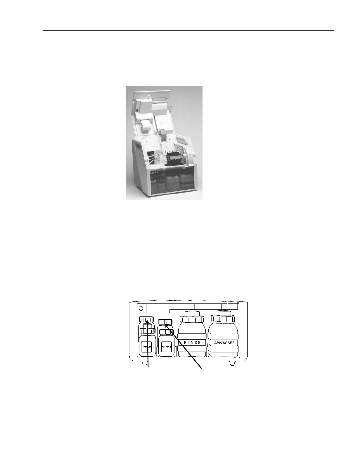
2 Description of the Analyzer
Cover
It is essential to ensure the cover of the analyzer is closed during
measurements and calibrations to prevent electrical interference and maintain
temperature stability of the measuring system.
The cover can be held in an open position using the door rod to secure the
door.
Fig. 2-3: View with open top cover
Bottle Compartment
In the bottle compartment the following reagents / containers are required
•
Waste
•
Rinse
•
B uffer T ype 1
•
Bu ffer Typ e 2
•
pH Reference So lution
•
Cleaning Solution
Cleaning Solution Buffer Type 2
Fig. 2-4: Reagents
NOTE: The ambient temperature for storing all reagents ranges from
5 °C to 30 °C (41 °F to 86 °F).
Operator’s Manual, AVL COMPACT 3, Rev. 2.0, June 1998 2-3
Page 58

2 Description of the Analyzer
Waste
Rinse
Buffer Type 1
(pH = 7.383)
Buffer Type 2
(pH = 6.841)
All liquids used by the analyzer are collected in the Waste container.
CAUTION: A trouble-free wash and dry cycle can be ensured only if the
system is completely sealed. The Waste container lid must be
tightly closed.
The Rinse is used:
•
to wash out the sample;
•
to wash out the calibratio n solution.
The Buffer Type 1 is used to determine the first point of a pH calibration.
The bottle is placed behind the Buffer Type 1 bottle inside the bottle
compartment.
The Buffer Type 2 solution is used to deter mine the second point of a pH
calibration.
pH Reference Solution
Cleaning Solution
This solution is pumped into the pH-reference electrode by means of a KCl
pressure circulation system and the sample.
The pH Reference Solution is transported only if the bottle cap is closed
tightly.
The bottle is placed behind the pH Reference Solution inside the bottle
compartment.
A cleaning cycle is automatically performed after 50 samples during the next
main calibration.
CAUTION: Do not mix or refill reagents.
Use only AVL reagents.
2-4 Operator’s Manual, AVL COMPACT 3, Rev. 2.0, June 1998
Page 59

2 Description of the Analyzer
Sample Fill Module
This module consists of the following parts:
•
Flap
•
Fill por t and tube
•
Sample drip tray
Flap
Fill port
Sample drip tray
Fig. 2-5: Sample fill module
Flap
Fill Port and Tube
Sample Drip Tray
The flap has to be opened for a sample input.
CAUTION: If the flap is opened by mistake, the running action will be
interrupted. The analyzer prompts the operator to close the flap
and a wash/dry cycle will be performed.
The fill port (see Fig. 2-5) allows samples to be injected or aspirated from
•
syringes,
•
AVL Microsampler and
•
capillaries without the need of adapters.
The sample drip tray is placed on the lower end of the fill module to avoid
sample spilling. The tray is replaced as part of the scheduled maintenance
procedures or when it becomes very soiled.
Operator’s Manual, AVL COMPACT 3, Rev. 2.0, June 1998 2-5
Page 60

2 Description of the Analyzer
Description of the Sample Path
Fill Port
Sample Inlet Path
Measuring Capillary
The sample is injected or aspirated into the fill port of the
AVL COMPACT 3 using a syringe, capillary or AVL Microsampler.
The fill port is made of soft PVC and serves as an interface between the
sample container and the sample path. The fill port is designed so those
samples can be injected or aspirated via syringe, capillary or Microsampler
without the need of an adapter.
The sample flows through the pre heating tube.
The metal sample inlet path heats the sample up to 37° C.
The sample inlet path is also the first contact for sample detection and the first
contact path (K
The analyzer aspirates the sample from the sample inlet path into the
measuring capillary.
In the measuring capillary, the sample contacts the electrodes. Before the
sample reaches the measuring chamber valve it passes the second electrical
contact for sample detection. In the measuring capillary, an electrical contact
for sample detection is positioned between the
The AVL COMPACT 3 detects the sample and controls the filling of the
measuring capillary by means of contact paths.
After the pH blood gas measurement is completed, the sample is moved into
the waste bottle.
- Mini Sample).
0
P
O2 and PCO2 Electrode.
Measuring Chamber
Valve
2-6 Operator’s Manual, AVL COMPACT 3, Rev. 2.0, June 1998
The electromagnetic measuring chamber valve closes the measuring chamber
and avoids the direct filling of a syringe sample into the measuring chamber.
The sample is pushed into a bypass tube. This construction ensure s a
continuous and bubble-free filling of the measuring chamber. It also prevents
electrode damage from excessive pressure.
Page 61

Measuring Chamber
Module
2 Description of the Analyzer
The measuring chamber module consists of the following parts:
DC
A
B
Fig. 2-6: Measuring chamber m odule
Measuring Capillary
A
measuring capillary
B
measuring chamber block
C
measuring chamber valve
D
electrodes
Fig. 2-7: Measuring capillary
In the measuring capillary the Blood Gas Electrodes and the pH Electrode are
in direct contact with the sample to measure the Blood Gas parameters and the
pH-value.
The measuring capillary is permanently illuminated so that the entire
aspiration cycle can be observed.
Operator’s Manual, AVL COMPACT 3, Rev. 2.0, June 1998 2-7
Page 62

2 Description of the Analyzer
Measuring Chamber
Block
Measuring Chamber
Valve
The entire module is thermostated at 37 °C.
The measuring chamber solenoid valve is located at the right end of the
measuring chamber block.
This valve prevents direct access from the pre-induction tube (i.e. syringe
injection) to the measuring chamber module to avoid damage of the electrodes.
Electrodes
The electrodes are inserted into the measuring chamber block from the rear.
The electrode tips proj ect into the measuring capillary thus
come into contact with the sample material.
The electrodes are color-coded for easy identification.
Listed from left to right:
white gray green blue
pH Reference pH
Fig. 2-8: Electrodes
P
CO
P
O
2
2
Peristaltic Pump
The peristaltic pump is used to transport all samples and liquid s inside the
analyzer.
Fig. 2-9: Peristaltic pump
2-8 Operator’s Manual, AVL COMPACT 3, Rev. 2.0, June 1998
Page 63

2 Description of the Analyzer
Rear Panel
Warning and identification plates with model and serial numbers are located
on the rear panel of the unit.
NOTE: Only a trained service engineer is authorized to open the rear panel.
Fig. 2-10: Rear panel
Fig. 2-11: Warning and ident ification plat es
Operator’s Manual, AVL COMPACT 3, Rev. 2.0, June 1998 2-9
Page 64

2 Description of the Analyzer
Interfaces
COM 3: 25-pin (female)
COM 2: 9-pin (female)
COM 1: 9-pin (female)
Gas Connections
Fig. 2-12: Interface
The standard bi-directional interface (RS232 C, Submin. D-connector) enables
the user to connect the analyzer with a Host Computer, an external printer or
ticket printer.
In addition, the unit is provided with an interface option for a Bar code
scanner and for data link with an AVL Oximeter or an AVL Electrolyte
Analyzer and / or with an external service modem.
Gas 2 (10 % CO2, balanced N2)
Gas 1 (5.5 % CO2, 20 % O2, balanced N2)
Fig. 2-13: Gas connections
Connections for gas tubing are located in the lower right corner of the rear
panel.
2-10 Operator’s Manual, AVL COMPACT 3, Rev. 2.0, June 1998
Page 65
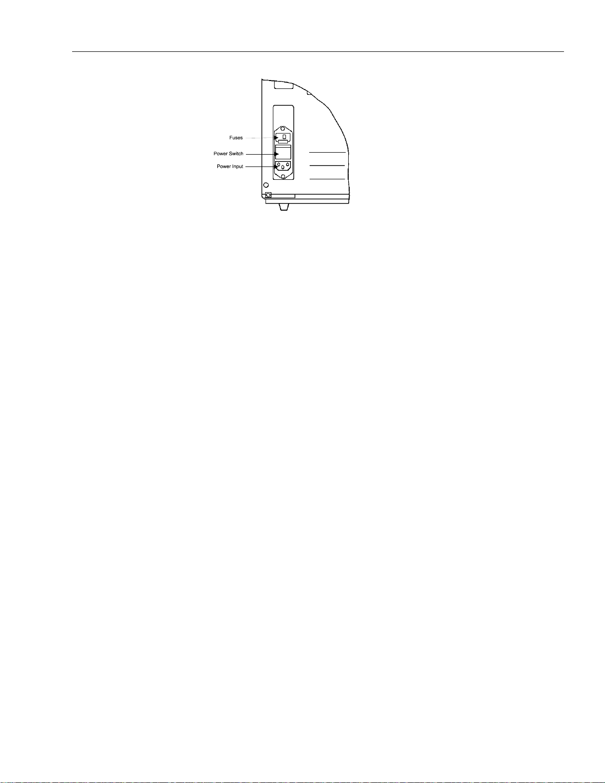
Power Switch Module
2 Description of the Analyzer
Fig. 2-14: Power switch module
This module consists of a power switch, power input, fuses, and a power line
filter.
Operator’s Manual, AVL COMPACT 3, Rev. 2.0, June 1998 2-11
Page 66

2 Description of the Analyzer
Operator Interface
Display
Keypad
The display helps you to operate the analyzer.
When the unit is ready for measurement, the display reads as follows:
4'#&;
(QTOGCUWTGOGPV
QRGPVJGHNCR
7UGTRTQITCOU!
First line: current status of the analyzer, actual time.
Second and third line: display instructions, alarms and measuring values.
Fourth line: indicates user programs and questions; selection,
activation and data input.
The keypad in conjunction with the display provides control of all analyzer
functions
Keys Function Data input
o
n
m
l
k
•
activates user programs
•
answers indicated questions
•
confirms indicated values
•
negates indicated questions
•
selects next function
•
negates indicated questions
•
selects previous function
•
interrupts the program sequence
•
interrupts all actions
•
exits user programs
•
jumps to previous menu
EXCEPT: calibrations and measurements: an interruption by
pressing k must be confirmed by pressing o .
•
confirms / completes data
input
•
input of time/date
•
input time/date
•
aborts data input
•
input of all numerical values
Except: time / date
• input of signs
• at each key touch the cursor
will be placed back for one
digit, without deleting other
digits
EXCEPT: patient number
2-12 Operator’s Manual, AVL COMPACT 3, Rev. 2.0, June 1998
Page 67

2 Description of the Analyzer
Timeout
If no key was pressed, the analyzer automatically returns within 30 sec from
each user program to 4'#&;.
Exception: the user program "System Test".
Operator’s Manual, AVL COMPACT 3, Rev. 2.0, June 1998 2-13
Page 68

2 Description of the Analyzer
2-14 Operator’s Manual, AVL COMPACT 3, Rev. 2.0, June 1998
Page 69

3 Installation, Shutdown
3 INSTALLATION / SHUTDOWN
Installation................................................................................................................... .............. 3-1
Location................................................................................................................................... 3-2
Solenoid Valve Relief Clamps ................................................................................................... 3-2
Peristaltic Pump Tube............................................................................................................... 3-3
Filling and Connecting the Bottles ............................................................................................3-4
Waste Bottle......................................................................................................................... 3-4
Rinse, pH Reference Solution, Buffer Type 1, Buffer Type 2, Cleaning Solution..................... 3-4
Calibration Gas Connection ......................................................................................................3-5
Electrodes ..................................................................................................................... ........... 3-6
pH Reference Electrode (white)............................................................................................. 3-6
Inserting Printer Paper............................................................................................................3-10
Shutdown ....................................................................................................................... ..........3-11
Longer than 3 Days.................................................................................................................3-11
Rinse and Dry the Tubes...................................................................................................... 3-11
Electrode Care....................................................................................................................3-12
Releasing the Peristaltic Pump Tube ....................................................................................3-13
Releasing the Tubes ............................................................................................................3-13
Storage, Transportation.......................................................................................................3-14
Operator’s Manual, AVL COMPACT 3, Rev. 2.0, June 1998 3-I
Page 70

Page 71

3 Installation / Shutdown
This chapter describes the installatio n and shutdown procedures.
Installation
After the AVL COMPACT 3 has been unpacked and placed in a location
according to the requirements described in chapter 1, the following steps
should be performed:
Check whether analyzer and accessories are complete and undamaged. Check
contents against the supplied packing list.
If parts are missing inform your AVL representative. In case of damage inform
your carrier immediately. Keep analyzer and packing material until any queries
have been addressed.
NOTE: Packing may vary by country and slight variation from the accessories
list.
Contact your AVL representative for your specific list.
3 Installation, Shutdown
Description
1 set dummy electrodes (four pieces)
1 pcs. lamp 28 V
1 pcs. 80 mAT / 250 V (F1/F2)
1 pcs. 1.6 AT / 250 V (F3 / mains fuse)
2 pcs. 3.2 AT / 250 V (F4)
1 pcs. nozzle cleaning needle
1 pcs. tub ing set for peristaltic pump
1 pcs. fill po rt
1 pcs. quad r ing seal for pH Reference Solution bo ttle
(28.17 x 3.53 mm)
1 pcs. quad ring seal for measuring chamber
(1.06 x 1.25 mm)
1 pcs. quad ring seal for waste (50.4 x 3.53 mm)
1 pcs. leak proof adapter (measuring chamber valve)
2
1 pcs. power cable (∅ = 1.5 mm
1 pcs. sample drip tray
1 pcs. operator’s manual
; length = approx. 2 m)
Operator’s Manual, AVL COMPACT 3, Rev. 2.0, June 1998 3-1
Page 72

3 Installation, Shutdown
Location
Solenoid Valve
Relief Clamps
For correct, trouble-free operation, the following environmental specifications
must be observed:
• Ambient temperature: +15 °C to + 32 °C (50 °F to 90 °F).
• Avoid direct sunlight.
• Avoid hazardous gases and vapors.
• Relative humidity: 20 - 90 %.
• Avoid locations beside strong electromagnetic fields (electric motors,
transformers, X-ray apparatus etc.). Avoid the use of cellular telephones
near the device.
• Avoid vibrations, use a solid surface.
• Allow sufficient space (at least 20 cm / 8 Inch minimum) around the
analyzer for air circulation and electrical supply.
In the AVL COMPACT 3 analyzer, relief clamps are inserted under the
solenoid valves to prevent tube damage.
Before installing the analyzer remove the relief clamps and reinsert it during
shutdown procedur e.
NOTE: Do not forget to remove the relief clamps, otherwise no proper start
up operation will occur.
The clamps designed for this pu rpose can easily be removed b y lifting
the solenoid fixtures.
Slightly pull the armature of the va lves when removing the relief
clamps. Take care for the solenoid valve relief cla mps, you will need it
for a possible later shutdown.
Open the cover of the analyzer to gain access to the solenoid valves relief
clamps.
Six of them (V3, V4, V5, V7, V11, V12) are located to the right of the
measuring chamber (see Fig. 3-1), one to the right of the peristaltic pump (see
Fig. 3-2).
Open the bottle compartment cover (transparent gray plastic) and r emove the
three solenoid valve red relief clamps from the solenoid valves (V6, V8 , V10)
in the bottle compartment (see Fig. 3-3).
Fig. 3-1: Solenoid valve relief clamps - fill module
3-2 Operator’s Manual, AVL COMPACT 3, Rev. 2.0, June 1998
Page 73
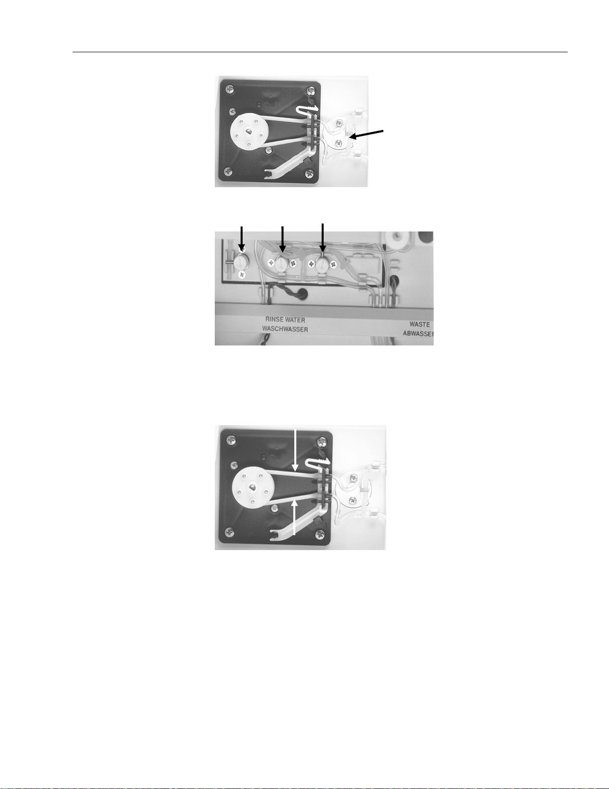
Fig. 3-2: Solenoid valve relief cl amps - peristal tic pump
3 Installation, Shutdown
Peristaltic Pump
Tube
Fig. 3-3: Solenoid valve relief cl amps - bottle c ompartment
Fig. 3-4: Peristaltic pump tubes
Procedure
• Push end of tension lever to the r ight and slightly against the pump plate
until it locks with a click.
Operator’s Manual, AVL COMPACT 3, Rev. 2.0, June 1998 3-3
Page 74

3 Installation, Shutdown
Filling and
Connecting the
Bottles
Located under the measuring chamber and the fill module, the reagent
compartment houses the fluid containers.
The screw-on caps with tubing for the containers are connected to the liquid
circulation system which projects from the rear wall of the reagent
compartment.
NOTE: Ensure to place the caps to the corresponding reagent bottles and pay
attention, that no tube is folded.
Waste Bottle
Rinse, pH Reference
Solution, Buffer Type 1,
Buffer Type 2,
Cleaning Solution
Before screwing the cap on the Waste bottle, ensure that the ring seal is
properly in place.
If the seal is in place, screw the cap onto the empty Waste container and insert
the bottle into its socket in the bottle compartment.
NOTE: Ensure that the Waste bottle is completely airtight to a llow a
trouble-free operation.
The necks of the bottles are sealed with aluminum foil.
Remove the foil by cutting along the edge of the bottleneck.
NOTE: When removing the foil, make sure that the fluid s are not
contaminated.
NOTE: If you do not use the Rinse reagen t, fill the bottle with distilled water
and add one ampoule of Rinse Additive.
Screw the caps on the bottles and place them in their sockets in the bottle
compartment.
NOTE: Before screwing on the cap of the pH Reference Solu tion bottle,
ensure that the ring seal is properly in place.
Ensure that the cap is screwed on finger tight otherwise the
pH Reference Electrode will not function p roperly.
After installing the pH Reference Solution, do not switch on the
analyzer before a pH Reference Electrode has been installed!
3-4 Operator’s Manual, AVL COMPACT 3, Rev. 2.0, June 1998
Page 75

Calibration Gas
Connection
3 Installation, Shutdown
The AVL COMPACT 3 needs two different calibration gases.
Gas 2 (10 % CO2, balanced N2)
Gas 1 (5.5 % CO2, 20 % O2, balanced N
Fig. 3-5: Gas connection
2
Fig. 3-6: Position of c alibration gas cylinder
Procedure
•
Install the pressure regulators on the new gas cylinders.
•
Insert the new cylinders in the holder and secure them.
•
Connect the tube s to the outlet of the gas reduction valve.
•
Connect the tubes to the connector nipples on the rear panel of the
AVL COMPAC T 3.
•
Open the valves of the gas cylinders again.
NOTE: Do not mix up bottles and tubes.
NOTE: The length of the gas tube is limited at 1m (3 ft). Avoid large distances
between analyzer and gas cylinder.
Please contact your AVL customer support if larger distances are
necessary.
Operator’s Manual, AVL COMPACT 3, Rev. 2.0, June 1998 3-5
Page 76

3 Installation, Shutdown
Electrodes
NOTE: Zero maintenance pH / Blood Gas Electrodes do not require any
preparation.
Fig. 3-7: Removal of transport housing
Before installing the remembranable electrodes r emove transport housing
(1) and pull (2)) and fit them with a new electrode housing (see
(twist
chapter 12, "Care and Maintenance of Remembranable pH / Blood Gas
Electrodes ").
NOTE: Save transport housing for possible storage or transport.
The electrodes do not require cleaning with electrode paste at this stage.
Install the electrodes from right to left in the following sequence:
•
P
O2 Electrode (blue)
•
P
CO2 Electrode (green)
pH-Reference Electrode
(white)
•
pH Electrode (gray)
Pull out the electrode clips and insert the electrodes into the measuring
chamber block.
Secure the electrodes with the clips and connect the electrode cables.
1. Carefully remove the protective caps from the pH Reference Electrode
nipples. Connect the unmarked tube to the lower nipple and the yellowcoded tube to the yellow-coded upper nipple.
Yellow marking
Fig. 3-8: pH Reference Electrode - yel low marking
3-6 Operator’s Manual, AVL COMPACT 3, Rev. 2.0, June 1998
Page 77

3 Installation, Shutdown
Replace the pH Reference Electrode housing with a new one.
Fill the pH Reference Electrode with pH Reference Solution, before
inserting into the measuring chamber block.
2. P lug the power cord into an electrical outlet and switch on the analyzer.
3. The following display appears:
%1/2#%6
2NGCUGYCKV
When the correct temperature is reached, the following display with the
correct temperature appears.
9#4/72
/%VGOR%
52VGOR%
During the warm up there is a conditioning of the PO2- and PCO2electrode.
9#4/72
2NGCUGYCKV
4. Check the automatic filling function of the pH Reference Electro de housing
(see chapter 9).
If the pH Reference Electrode is filled, continue with item 5.
Operator’s Manual, AVL COMPACT 3, Rev. 2.0, June 1998 3-7
Page 78

3 Installation, Shutdown
If the pH Reference Electrode was not filled:
Take pH Reference Electrode out of the measuring chamber.
NOTE: Do NOT disconnect cable and tubes!
Activate:
/CKPVGPCPEG! oZm
4GHg'NGEVTQFG! o
75'4241)4#/5
4GHgGNGEVTQFG
(KNNGNGEVTQFG!
Press o .
This function activates the automatic filling of the pH Reference Electrode
housing.
On completion of the filling procedure, the following display appears:
75'4241)4#/5
4GHgGNGEVTQFG
(KNNGNGEVTQFG!
5. P ress n when the electrode is filled.
The permeability of the pH Reference Electrode diaphragm should be
tested.
Carefully touch the electrode tip with a clean dry tissue.
75'4241)4#/5
4GHgGNGEVTQFG
%JGEMRGTOGCDKNKV[!
Press o to confirm.
Observe the electrode tip for the formation of a small droplet of pH
Reference Solution.
75'4241)4#/5
4GHgGNGEVTQFG
%JGEMRGTOGCDKNKV[!
3-8 Operator’s Manual, AVL COMPACT 3, Rev. 2.0, June 1998
Page 79

3 Installation, Shutdown
If no droplet has formed on the tip, press o to confirm and repeat this
procedure, otherwise exit this program by pressing k .
If again no droplet has formed replace the pH Reference Electrode housing
in accordance with the instructions given in chapter 9, "Maintenance".
Fig. 3-9: pH Reference Electrode - dropl et
If the droplet has formed, wipe it off carefully, insert the electrode into the
measuring chamber and secure with the clip.
Press k to exit the program.
Operator’s Manual, AVL COMPACT 3, Rev. 2.0, June 1998 3-9
Page 80

3 Installation, Shutdown
Inserting Printer
Paper
1. Push the paper roll holder slightly to the side
2. Put a new roll of paper into the mounting support.
3. Insert the paper in the feeder.
4. Press the paper feed (black) button until the paper ap pears at the outside of
the cover.
4
3
1 / 2
Fig. 3-10: Paper insertion
NOTE: The paper is heat-sensitive on one side only. Make sure that it is
inserted correctly.
3-10 Operator’s Manual, AVL COMPACT 3, Rev. 2.0, June 1998
Page 81

Shutdown
3 Installation, Shutdown
If the AVL COMPACT 3 is to be put out of use for a longer period of time, it
is possible to activate the economy standby mode. During this time, the
analyzer does not need Buffer Type 1 or Buffer Type 2, but the electrodes
have the optimal conditioning.
If necessary, a "Manual Standby" or "Automatic Standby" can be activated.
For details, see chapter 8 "Settings" section " Manual Standby" or "Automatic
Standby".
This economy standby mode can be canceled at any time. After performing the
necessary calibration the analyzer is 4'#&;.
Longer than 3 Days
Rinse and Dry the
Tubes
If your AVL COMPACT 3 is to be shut down completely for more than 3 days,
you have to empty the tubes, remove the electrodes from the measuring
chamber and secure some of the tube valves with the relief clamps.
Procedure
4'#&;
(QTOGCUWTGOGPV
QRGPVJGHNCR
7UGTRTQITCOU!
1. Take both tubes off the pH Reference Electrode and connect them with
each other by means of a nipple. Close the two nipples of the pH Reference
Electrode with the two supplied red stoppers.
NOTE: A capillary tube may also be used instead of a n ipple.
Do not insert the ends of the capilla ry into the tubes deeper th an
10 mm.
2. Empty Buffer Type 1, Buffer Type 2, pH Reference Solution and Cleaning
Solution, rinse them, fill them with distilled water and put them back into
the analyzer.
3. Activate:
7UGTRTQITCOU! oZm
/CKPVGPCPEG! oZm
5JWVFQYP! o
75'4241)4#/5
5JWVFQYP
4KPUG!
Operator’s Manual, AVL COMPACT 3, Rev. 2.0, June 1998 3-11
Page 82

3 Installation, Shutdown
Press o.
A rinsing cycle is now activated during which the entire reagent inlet and
outlet tubing system is rinsed.
Empty the bottles of Buffer Type 1, Buffer Type 2, pH Reference Solution,
Cleaning Solution and Rinse.
75'4241)4#/5
5JWVFQYP
&T[!
Press o.
75'4241)4#/5
5JWVFQYP
&T[CEVKXCVGF
Electrode Care
The liquids are aspirated and the tubing system is dried.
75'4241)4#/5
5JWVFQYP
5YKVEJQHHCPCN[\GT
4. Switch off the power supply.
5. Close the valve of the calibration gas cylinders.
6. I nsert the solenoid valve relief clamps.
7. Empty, decontaminate and dry the waste bottle and put it back into the
analyzer.
Disconnect the electrode cables and lift the electrode clips.
The electrodes may now be removed.
NOTE: Reinsert the electrode clips to avoid losing them.
Storage for only one day
To prevent the electrodes from drying out fill the protective caps with:
• pH Electrode: Buffer Type 1
P
CO2 Electrode:
•
•
P
O2 Electrode: do not fill
P
CO2/TCO2 Filling Solution
• pH Reference Electrode: pH Reference Solution
and seal them with Parafilm
®
.
3-12 Operator’s Manual, AVL COMPACT 3, Rev. 2.0, June 1998
Page 83
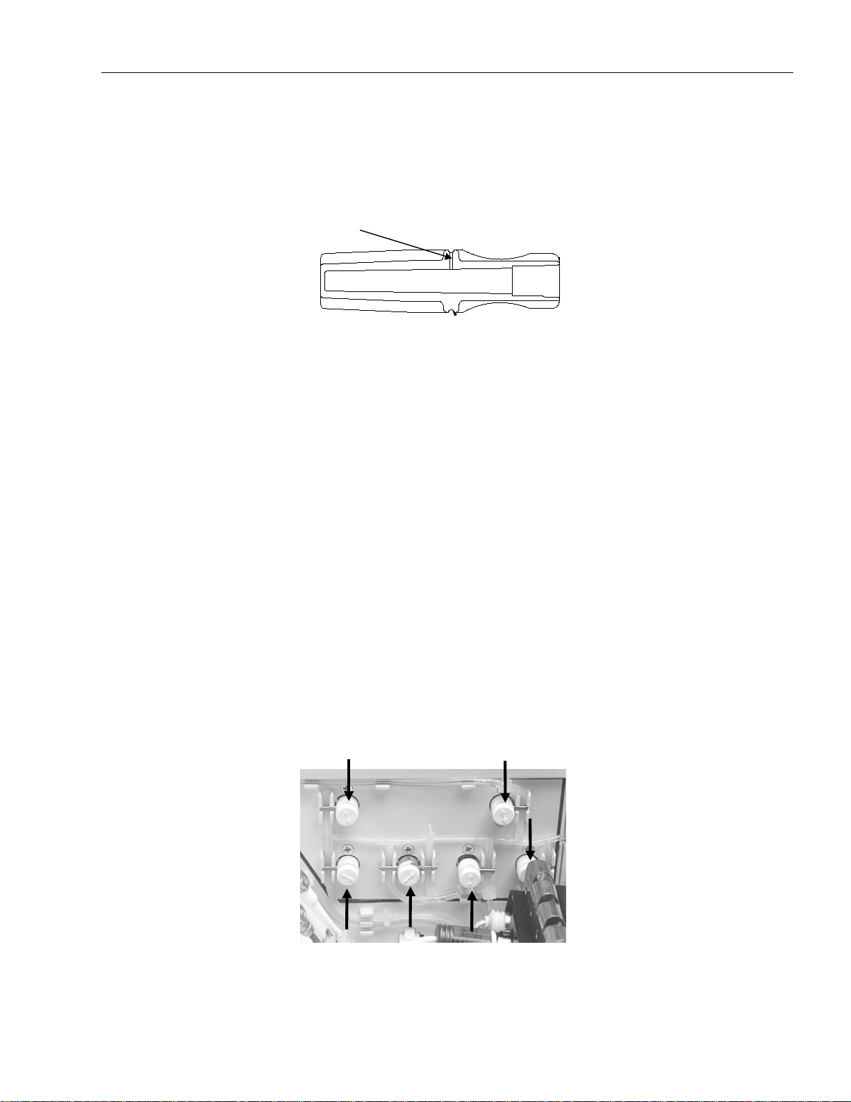
Releasing the Peristaltic
Pump Tube
3 Installation, Shutdown
Transport (only for Remembranable Electrodes)
•
Remove the electrode housing from the corresponding electrode.
•
Fill the transpo rt housing with the corresponding electr olyte (Exception:
P
O2 Electrode):
•
Remove the o utside O-ring fro m the transport housing fo r opening the
discharge pore
Fig. 3-11: Transport housing
•
Fit the electrodes with the filled transport ho using
Unlock tension lever. Push on hook-shaped until tensio n lever moves left and
pump tube tension is released.
Releasing the Tubes
To prevent tube damage in the AVL COMPACT 3 analyzer during transport,
relief clamps are inserted under the solenoid valves to.
NOTE: The clamps designed for this p urpose can easily be removed by lifting
the solenoid fixtures.
Six of them (V3, V4, V5, V7, V11, V12) are inserted to the right of the
measuring chamber (see Fig. 3-12), one to the right of the peristaltic pump
(see Fig. 3-13).
The remaining three red solenoid valve relief clamps have to be inserted (V6,
V8, V10) in the bottle compartment (see Fig. 3-14).
Fig. 3-12: Solenoid valve relief clamps - fill module
Operator’s Manual, AVL COMPACT 3, Rev. 2.0, June 1998 3-13
Page 84
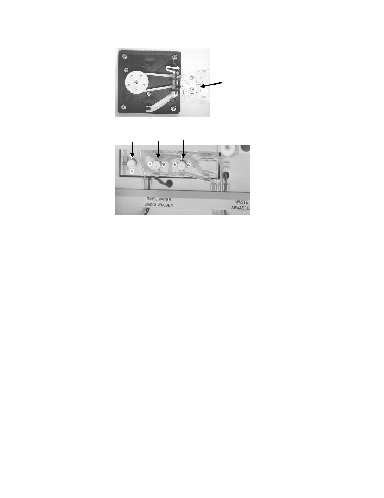
3 Installation, Shutdown
Fig. 3-13: Solenoid valve relief cl amps - peristal tic pump
Storage, Transportation
Fig. 3-14: Solenoid valve relief cl amps - bottle c ompartment
Protect the AVL COMPACT 3 with a dust cover during storage.
For transportation purposes use the original shaped parts packing material.
3-14 Operator’s Manual, AVL COMPACT 3, Rev. 2.0, June 1998
Page 85

4 Patient Testing
4 PATIENT TESTING
Sample Preparation....................................................................................................................4-1
Important when Storing Blood .................................................................................................. 4 -1
Sample Measurement................................................................................................................. 4-2
Syringe Measurement ...............................................................................................................4-2
Capillary or Microsampler Measurement ................................................................................... 4-4
Micro sample ................................................................................................................... ........ 4-6
Printout of Results.................................................................................................................... 4-9
Password Option................................................................................................................ ......4-10
Password - OFF......................................................................................................................4-10
Password - ON (Measurement - ON)........................................................................................4-10
Password - ON (Measurement - OFF) ......................................................................................4-11
Parameter and Data Input .......................................................................................................4-12
Parameter Input ......................................................................................................................4-12
Modification of Patient’s Temperature.................................................................................. 4-13
Modification of tHb Value...................................................................................................4-14
Modification of tHb Type for Fetal and Adult Blood.............................................................4-14
F
Modification of Fraction of Inspired Oxygen (
Modification of Respiratory Quotient (RQ) .......................................................................... 4-15
Modification of Half- Saturation Pressure ............................................................................4-15
Modification of Sample Type............................................................................................... 4-16
Input of Patient- Related Data................................................................................................. 4-17
Entering Patient’s Number (Manual).....................................................................................4-18
Entering Patient’s Number (Barcode) ...................................................................................4-18
Entering Patient’s Sex ..........................................................................................................4-18
Entering Patient’s Age .........................................................................................................4-18
IO2).............................................................4-14
Printout....................................................................................................................................4-19
Measurement Reports .............................................................................................................4-20
Data Input...........................................................................................................................4-20
Reports ...............................................................................................................................4-20
Calibration Reports ................................................................................................................ 4-21
Error Report................................................................................................................... ........4-21
System Status.................................................................................................................. .......4-22
Operator’s Manual, AVL COMPACT 3, Rev. 2.0, June 1998 4-I
Page 86

Page 87
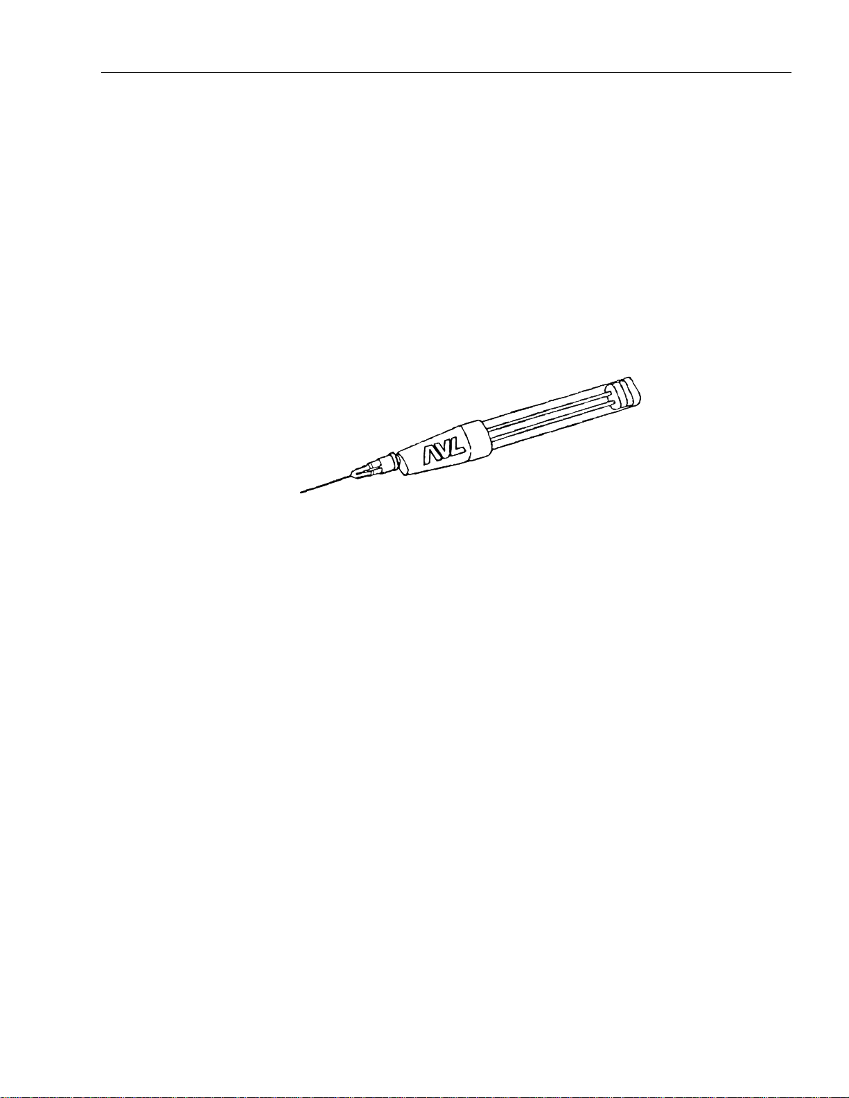
4 Patient Testing
This chapter describes routines used to o perate of AVL COMPACT 3.
Sample Preparation
NOTE: Always observe the laboratory regulations, when collecting blood.
For capillary blood samples, it is advisable to use AVL capillary tubes, which
contain a special Heparin coating.
The most advanced and user-friendly device for collecting arterial blood is the
AVL Microsampler.
4 Patient Testing
Important when
Storing Blood
Fig. 4-1: AVL Microsampler
The use of very thin needles prevents common complications such as
hematoma, thrombosis etc. which may occur after an arterial puncture.
NOTE: When the Microsampler needle punctures an artery, a pulsating blood
flow filling of the capillary tube ca n be observed.
Continuous flow indicates that a vein has been punctured.
CAUTION: The higher the temperature of a sample, the faster and more
intensive its metabolism (means change of Blood Gas and pH
values).
The ideal temperature for long-term storing of blood is approx. 4° C
(39 °F).
At this temperature the metabolism of a sample and, as a consequence, its
oxygen consumption are lowest.
At a temperature of 4° C, a sample may be kept for up to two hours without
significant changes of its Blood Gas and pH values.
When using an AVL Microsampler, the sample does not require icing for up to
30 min.
For details, please refer to chapter 13!
Operator’s Manual, AVL COMPACT 3, Rev. 2.0, June 1998 4-1
Page 88
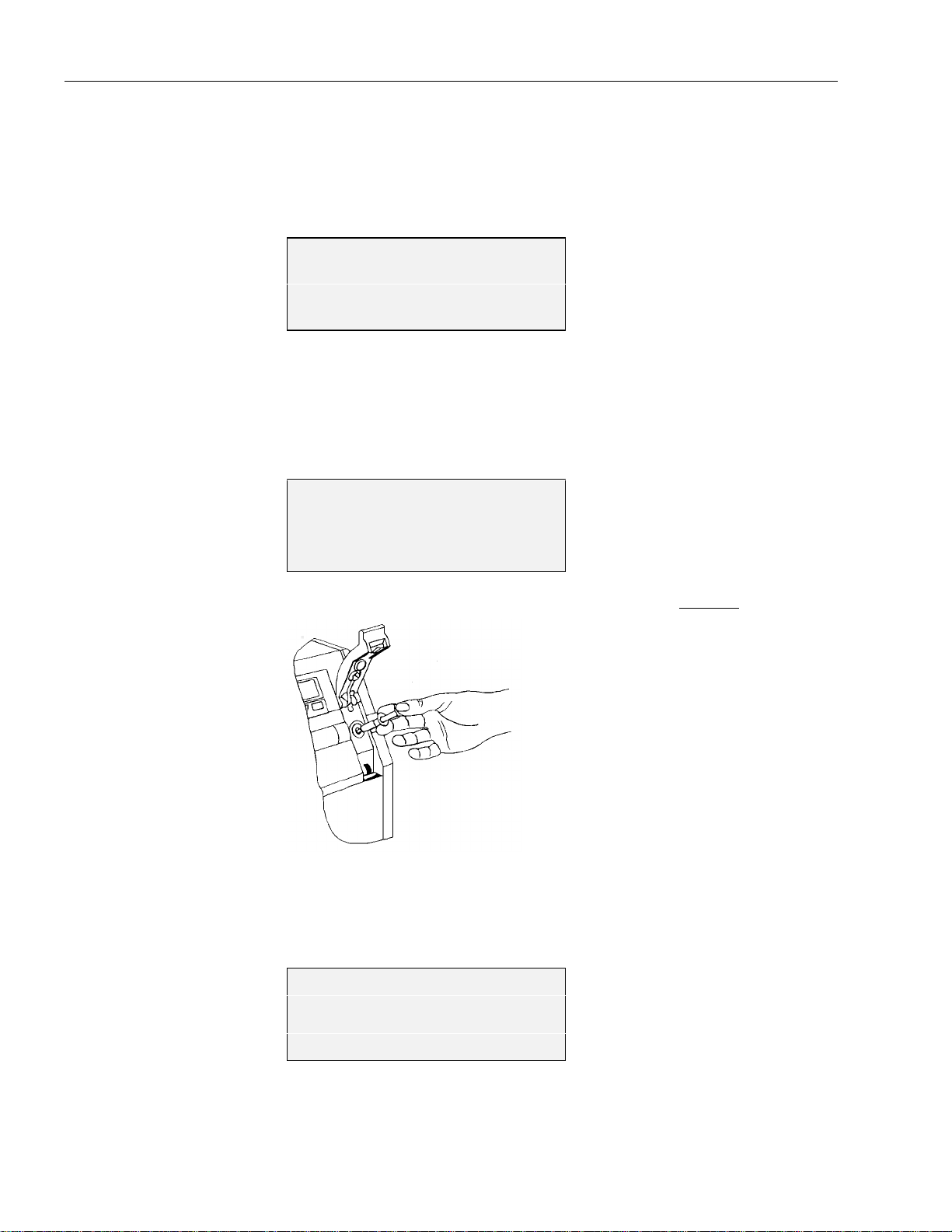
4 Patient Testing
Sample Measurement
Syringe
Measurement
Before a measurement can be performed, the analyzer must be in 4'#&;
mode.
NOTE: Before measurement, turn the syringe in your hand for about 10
Open the flap.
4'#&;
(QTOGCUWTGOGPV
QRGPVJGHNCR
7UGTRTQITCOU!
seconds to mix the sample and remove any air by injecting it onto a
cotton swab.
/'#574'/'06
+PLGEVUCORNGQT
UGNGEVCURKTCVKQP
#URKTCVKQP!
Insert the syringe into the fill port and inject the sample slowly.
Fig. 4-2: Syringe measurem ent
As soon as the requisite sample volume is injected, an acoustic signal will
sound and the following display appears:
/'#574'/'06
4GOQXGU[TKPIG
ENQUGVJGHNCR
Remove the syringe from the fill port and close the flap.
4-2 Operator’s Manual, AVL COMPACT 3, Rev. 2.0, June 1998
Page 89

4 Patient Testing
NOTE: If the flap is opened again while the sample is being aspirated and not
closed before the countdown reaches 000, a continuous beep will
sound until the flap is closed.
If the flap is opened during the measurement, the measurement will be
aborted.
NOTE: Do not open the cover during measurements!
/'#574'/'06
'FKVRCVKGPVFCVC!
The analyzer performs a fully automatic measurement.
The transparent, illuminated measuring channel enables the user to observe the
movement of a sample and to identify blockages or air bubbles. During
measurement, data input (input patient or sample related data) is possible.
If a barcode scanner is installed, it is possib le to scan in the patient number
during measurement (from sample stop up to reaching 4'#&;) as well as
during the function "Da ta input" - " Patient number" .
Please refer to chapter 8 "Settings", section "Interfaces" for further
information.
The countdown running in the upp er right co rner of the disp lay during the
P
measurement ends with the display of measured pH,
CO2 and PO2 and one of
the calculated values (for details, please refer to chapter 8, section " Settings" "Display") and printout of the results.
%10&+6+10+0)
R*g2%1g
21g$'g
'FKVRCVKGPVFCVC!
On completion of the measurement, the results are displayed and printed out,
and a gas conditioning is started. As soon as the countdown reaches 20
seconds, an asterisk (*020) appears to indicate that the flap can now be opened
for further measurement (max. 4 times) before the end of the conditioning
cycle is reached.
If the flap is not opened before completion of the countdown, the analyzer
returns to 4GCF[ and the display will read as follows:
4'#&;
(QTOGCUWTGOGPV
QRGPVJGHNCR
7UGTRTQITCOU!
Operator’s Manual, AVL COMPACT 3, Rev. 2.0, June 1998 4-3
Page 90

4 Patient Testing
Capillary or
Microsampler
Measurement
Before a measurement can be performed, the analyzer must be in the 4'#&;
mode.
Fig. 4-3: Capillary measurement
4'#&;
(QTOGCUWTGOGPV
QRGPVJGHNCR
7UGTRTQITCOU!
Open the flap.
/'#574'/'06
+PLGEVUCORNGQT
UGNGEVCURKTCVKQP
#URKTCVKQP!
Press owhe n " #URKTCVKQP!" is indicated.
Carefully insert the capillary into the fill port.
NOTE: At least 55µ l sample volu me is required!
If under "Settings" the function "Mini sample" was activated, the following
display appears:
/'#574'/'06
5CORNG
KUCURKTCVGF
/KPKUCORNG!
4-4 Operator’s Manual, AVL COMPACT 3, Rev. 2.0, June 1998
Page 91

4 Patient Testing
Press o and only 60 µ l sample will be aspirated. As soon as an acoustic
signal will sound, remove the capillary and close the flap. The remaining
sample volume can be used for measurements in another analyzer (oximeter or
ISE).
If the displayed "Mini sample" was not confirmed by o, the sample will be
aspirated as long as the measuring chamber is completely filled.
After the acoustic signal will sound, remove the capillary and close the flap.
NOTE: If the flap is opened again, while the sample is being aspirated and
not closed before the countdown reaches 000, a continuous beep will
sound until the flap is closed.
If the flap is opened during the measurement, the measurement will be
aborted.
NOTE: Do not open the cover during measurements!
/'#574'/'06
'FKVRCVKGPVFCVC!
The analyzer performs a fully automatic measurement.
The transparent, illuminated measuring channel enables the user to observe the
movement of the sample and to identify blockages or air bubbles.
During measurement, data input is possible.
If a barcode scanner is installed, it is possib le to scan in the patient number
during measurement (from sample stop up to reaching 4'#&;) as well as
during the function "Da ta input" - " Patient number" .
Please refer to chapter 8 "Settings", section "Interfaces" for further
information.
The countdown running in the upp er right co rner of the disp lay during the
P
measurement ends with the display of measured pH,
CO2 and PO2 and one of
the calculated values (for details, please refer to chapter 8, " Settings", section
"Display") and printout of the results.
%10&+6+10+0)
R*g2%1g
21 g$'g
'FKVRCVKGPVFCVC!
Operator’s Manual, AVL COMPACT 3, Rev. 2.0, June 1998 4-5
Page 92

4 Patient Testing
On completion of the measurement, the results are displayed and printed out,
and a gas conditioning is activated. As soon as the countdown reaches 20
seconds, an asterisk (*020) appears to indicate that the flap can now be opened
for further measurement (max. 4 times) before the end of the conditioning
cycle is reached.
If the flap is not opened before completion of the countdown, the analyzer
returns to 4GCF[ and the display will read as follows:
4'#&;
(QTOGCUWTGOGPV
QRGPVJGHNCR
7UGTRTQITCOU!
Micro sample
The micro sample is only offered as a measurement variation for capillary
samples, smaller than 55µl and with a minimal volume of 25 µl. The micro
sample will automatically be identified during aspiration of the capillary
sample. If the sample volume is greater than 25 µl, the operator can choose
micro sample measurement. If the question /+%415#/2.'! is answered
with n or the time out has expired, the sample will be rejected with the
error signal 0Q5CORNG Thereafter, the analyzer carries out a wash-/dry
cycle and conditioning process and returns to 4'#&;.
P
O2, PCO2 and pH parameters can be
The
chosen and measured individually, according to the order of the electrodes in
the measuring chamber.
P
NOTE:The
If a parameter (
the sample by pressing l over the desired sample. The sensor must be
completely covered by the sample. Press o to confirm the actual
measurement.
If the parameter is in alarm, this particular parameter cannot be selected and is
automatically passed without appearing on the display. The micro sample
measurement is shown as /+%41 on the display.
O2-measurement begins immediately after a micro sample has
been detected (in this case, the sample is properly positioned as a
result of the defined minimum volume) and the sample is then either
disregarded or measured, depending on the chosen variation.
P
CO2 or PO2) is chosen with o , the operator must position
Procedure
4'#&;
(QTOGCUWTGOGPV
QRGPVJGHNCR
7UGTRTQITCOU!
Open the flap.
4-6 Operator’s Manual, AVL COMPACT 3, Rev. 2.0, June 1998
Page 93

4 Patient Testing
/'#574'/'06
+PLGEVUCORNGQT
UGNGEVCURKTCVKQP
#URKTCVKQP!
Press o when #52+4#6+10! is shown on the display.
The sample will be aspirated.
A micro sample measurement is automatically performed when the sample
volume is less than 55 µl. If the sample is greater than 25 µl, the following
appears on the display:
/'#574'/'06
4GOQXGECRKNNCT[
ENQUGVJGHNCR
/KETQUCORNG!
Close the flap and the following is shown:
/'#574'/'06
/KETQUCORNG!
Confirm with o .
If n is pressed or after conclusion of time out, the sample will be washed
out and the analyzer returns to the 4'#&; mode.
/'#574'/'06
21OGCUWTGOGPV!
Press o to perform the PO2 measurement. If the PO2 measurement is not
selected, the already scanned in values will also be canceled.
P
After the
O2 measurement, or when this is not selected by pressing n, the
following appears on the display:
/'#574'/'06
2%1OGCUWTGOGPV!
Press o to perform the PCO2 measurement.
Operator’s Manual, AVL COMPACT 3, Rev. 2.0, June 1998 4-7
Page 94

4 Patient Testing
/'#574'/'06
2QUgYKVJ72
5CORNGRQUKVKQPGF!
By pressing l you can position the sample. The sample should be
positioned uninterrupted. The sample should reach at least to the middle of the
P
connecting capillary between the pH- and
Confirm the correct position and start the measurement by pressing o .
P
After completion of the
offered. At the pH-measurement the pH-reference electrode as well as the pHelectrode have to be completely covered by the sample.
CO2 measurement, the pH-measurement will be
CO2-electrodes.
4-8 Operator’s Manual, AVL COMPACT 3, Rev. 2.0, June 1998
Page 95

4 Patient Testing
Printout of Results
Immediately after the results are displayed, the results are printed on the
thermal printer.
For a detailed description of reports, see chapter 12, "Appendix", section
"Description of Various Reports".
AVL COMPACT 3
BLOOD GAS
header
ACID BASE REPORT
Pat.Name:
Age: 36 F
Pat.no.: 18
Sample: CAPILLARY
cap.
Mo,17-Nov-97 15:54
No.: 30
Baro 724.8 mmHg
#tHb A 15.2 g/dL
#Temp 37.0 38.2 ÀC
...........actual date / time
...........sample number
...........air pressure
patient data
input values
pH 7.200 7.184
PCO2 17.0 17.9 mmHg
BE - 19.3 mmol/l
BEecf - 19.8 mmol/l
BB 28.7 mmol/l
HCO3 6.4 mmol/l
PO2 126.3 133.4 mmHg
O2sat 97.4 %
Op.ID.:
#Input values
...........measured value
...........calculated value
...........operator identity
measured values
calculated values
NOTE: For details, please refer to chapter 8, “Settings“.
To set the layout of this report, activate the program “Settings“ "Report" - "Report Editor“.
Operator's Manual, AVL COMPACT 3, Rev. 2.0, June 1998 4-9
Page 96

4 Patient Testing
Password Option
Password - OFF
If the function "Password" is activated in the progra m function "Settings" (for
details see chapter 8, section "Barcode Scanner", or "Password"), the
following condition for measurement is given:
4'#&;
(QTOGCUWTGOGPV
QRGPVJGHNCR
7UGTRTQITCOU!
The measurement can be performed as usual.
If a barcode scanner is installed, it is possib le to scan in the patient number
during measurement (within the sample stop time and before the measurement
and calculated values appear on the display), as well as during the "Data
input" function.
Please refer to chapter 8 "Settings", section "Interfaces" for further
information.
Password - ON
(Measurement - ON)
/'#574'/'06
(QTOGCUWTGOGPV
QRGPVJGHNCR
2CUUYQTF!
The measurement can be performed without scanning in the password. In order
to activate the program functions, either password-code 1 or password-code 2
must be scanned in.
The operator identification (OP . ID) can only be scanned in during the
4'#&; mode, with the use of the barcode scanner.
Details pertaining to the use of password-codecards can be found in
chapter 8, "Settings", section " Password" .
4-10 Operator’s Manual, AVL COMPACT 3, Rev. 2.0, June 1998
Page 97

Password - ON
(Measurement -OFF)
4 Patient Testing
4'#&;
+PRWVRCUUYQTF
2CUUYQTF!
A measurement can only be started, if a password-codecard is scanned in.
Scanning in the passw ord-codecard 3
4'#&;
(QTOGCUWTGOGPV
QRGPVJGHNCR
2CUUYQTF!
The operator is only able to perform a measurement, but has no access to the
program functions.
Scanning in the passw ord-codecard 1 and 2
4'#&;
(QTOGCUWTGOGPV
QRGPVJGHNCR
7UGTRTQITCOU!
The operator is able to perform measurements and can also activate program
functions.
CAUTION: If a barcode scanner is installed, it is possible to scan in the
patient number during measurement (from sample stop up to
reaching 4'#&;) as well as during the function "Data input"
- "Patient number".
The operator identification (OP. ID) can o nly be read in with
the barcode scanner during the 4'#&; mode.
Details pertaining to the use of password code cards can be found in
chapter 8, "Settings", section " Password“.
Operator’s Manual, AVL COMPACT 3, Rev. 2.0, June 1998 4-11
Page 98

4 Patient Testing
Parameter and Data Input
During and after a measurement, the user may enter or reset various
parameters and patient-related data (e.g. the patient temperature). This can be
done only for the current measurement.
If a barcode scanner is installed, it is possib le to scan in the patient number
during measurement (from sample stop up to reaching 4'#&;) as well as
during the function "Data input" - "P atient number". Further it is po ssible to
scan in the OP ID before a measurement (before the flap will be opened).
Standard values (e.g. the patient’s temperature,
which may be modified if necessary.
F
IO2 etc.) are default settings,
Parameter Input
The input of patient-related and sample-specific data overwrites the preset
default values for the current measurement.
The data input is possible during measurement or immediately thereafter, as
long as the results are displayed.
During the measurement
/'#574'/'06
'FKVRCVKGPVFCVC!
Press o .
75'4241)4#/5
'FKVRCVKGPVFCVC
2CTCOGVGTUKPRWV!
Press o.
Select the desired parameter with m or l and confirm by pressing o.
After the measurement
%10&+6+10+0)
R*g2%1g
21g$'g
'FKVRCVKGPVFCVC!
Press o .
4-12 Operator’s Manual, AVL COMPACT 3, Rev. 2.0, June 1998
Page 99

4 Patient Testing
NOTE: If none of the following parameters is selected before the measurement
is finished, the analyzer automatically returns to the highest menu
level %10&+6+10+0) or 4'#&;).
75'4241)4#/5
'FKVRCVKGPVFCVC
2CTCOGVGTUKPRWV!
Press o and select the desired parameter with m or l and confirm
the selected parameter by pressing o.
The following parameters can be modified:
• Pa tient’s temperature
• tHb value
• Hb-type for fetal and adult blood
• Fractio n of inspired oxygen (
F
IO2)
• Respiratory quotient (RQ)
• Half-saturation pressur e (
P
50)
• Sample Type (cap. / art. / venous)
Modification of
Patient’s Temperature
Activate:
2CTCOGVGTUKPRWV! o
2CVg6GORGTCVWTG! o
The displayed temperature may now be varied with the numeric keypad.
Available input range: 14 °C ... 44 °C (57.2 °F ... 111.2 °F).
Preset value: 37 °C
When you confirm the selected temperature with o , the display will fade
out.
At this point, you may select another parameter with mor l exit from
the program by pressing k.
Operator’s Manual, AVL COMPACT 3, Rev. 2.0, June 1998 4-13
Page 100

4 Patient Testing
2
Modification of tHb
Value
Modification of tHb
Type for Fetal and
Adult Blood
Activate:
2CTCOGVGTUKPRWV! oZm
V*D! o
The displayed tHb value may now be varied with the numeric keypad.
Available input range: 1.0 ... 26.0 g/dL
Preset value: 15 g/dL
When you confirm the selected tHb value with o , the display will fade out.
At this point, you may select another parameter with m or l or exit the
program by pressing k.
Activate:
2CTCOGVGTUKPRWV! oZm
Modification of
Fraction of Inspired
Oxygen (FIO
)
#FWNVHGVCN*D! o
The analyzer calculates the oxygen saturation values on the basis of a standard
ODC (Oxygen Dissociation Cur ve).
This ODC is, however, different for normal adult blood and for children’s
blood.
On the display appears "adult" and "fetal"; the selected parameter is blinking.
Select either "adult" or "fetal" by pressing mor l.
When you activate the blinking parameter with o , the display will fade out.
At this point, you may select another parameter with mor lor exit the
program by pressing k.
Activate:
2CTCOGVGTUKPRWV! oZm
(+1! o
This parameter is used to calculate the alveolar-arterial oxygen partial
pressure difference (AaDO
F
The displayed
IO2 value may now be varied with the numeric keypad.
).
2
Available input range: 0.11 ... 0.99
Preset value: 0.21
F
When you confirm the selected
IO2 value with o , the display will fade
out.
At this point, you may select another parameter with mor l or exit the
program by pressing k.
4-14 Operator’s Manual, AVL COMPACT 3, Rev. 2.0, June 1998
 Loading...