

Page 1
Accu-Chek® Inform II
BLOOD GLUCOSE MONITORING SYSTEM
Operator’s Manual
Page 2

Revision History
Manual version Revision date Changes
Version 1.0 2008-01 New document
Version 2.0 2009-08 Update, new SW version 02.00
Version 3.0 2010-09 Update, new SW version 03.00
Version 4.0 2012-11 Update, new SW version 03.04 (OTS, OTE), revision
Cleaning/Disinfection section; misc. editorial revisions
Version 5.0 2013-09 Transition to new meter hardware: 2D barcode scan-
ner, modifications to wireless LAN option (separate
insertable RF card replaced by integrated WLAN component); new battery pack. Update to SW 04.00; misc.
editorial revisions.
2
Page 3

A
A
CCU-C
HEK
CCU-
HEK
Operator’s Manual
®
Inform II System
Version 5.0
0 4807839001 (05) 2013-09 EN
Page 4

© 2008-2013, Roche Diagnostics. All rights reserved.
The contents of this document, including all graphics, are the property of Roche Diagnostics. No part of this
document may be reproduced or transmitted in any form or by any means, electronic or mechanical, for any
purpose, without the express written permission of Roche Diagnostics. Roche Diagnostics has made every
reasonable effort to ensure that all the information contained in this manual is correct at the time of printing.
However, Roche Diagnostics reserves the right to make any changes necessary without notice as part of
ongoing product development.
Please send questions or comments about this manual to your local Roche representative.
ACCU-CHEK, ACCU-CHEK INFORM, ACCU-CHEK PERFORMA and COBAS are trademarks of Roche.
All other trademarks are the property of their respective owners.
The Wi-Fi CERTIFIED Logo is a certification mark of the Wi-Fi Alliance.
4
Page 5
On the packaging, on the identification plate of the meter, the battery pack, the base unit, or the code key
reader you may encounter the following symbols, shown here with their meaning:
Caution, consult accompanying documents. Refer to safety-related notes in the instructions
for use accompanying this product.
Temperature limitation (Store at)
Manufacturer
Catalog number
IVD
7.5V 1.7A
On meters with WLAN capability:
For other WLAN certifications, see label on bottom of battery compartment and list included in meter kit.
In vitro diagnostic medical device
This product fulfills the requirements of the European Directives 98/79/EC on in vitro
diagnostic medical devices and 1999/5/EC on radio and telecommunications terminal
equipment (R&TTE).
The system fulfills the Canadian and U.S. safety requirements (UL LISTED, in accordance
with UL 61010-1 and CAN/CSA-C22.2 No. 61010-1).
Power supply connection
This device complies with Part 15 of the FCC Rules and with RSS-210 of Industry Canada.
The compliance mark indicates that the product complies with the applicable standard and
establishes a traceable link between the equipment and the manufacturer, importer or their
agent responsible for compliance and for placing it on the Australian and New Zealand
market.
5
Page 6

This page intentionally left blank.
6
Page 7

1 Introduction 13
1.1 Before you start......................................................................................................................................... 13
Intended use ...................................................................................................................................... 13
Important information regarding use ....................................................................................... 13
If you need help................................................................................................................................ 14
Note on the use of “base unit” in this manual...................................................................... 14
Note on illustrations in this manual .......................................................................................... 14
What can the system do for you? .............................................................................................. 15
1.2 Important safety instructions and additional information......................................................... 16
Important information regarding safety................................................................................... 17
Disposal of the system ................................................................................................................... 18
Product safety.................................................................................................................................... 19
General care....................................................................................................................................... 19
Accessory box ................................................................................................................................... 19
Meter .................................................................................................................................................... 19
Automatic power-off....................................................................................................................... 19
Battery Pack ....................................................................................................................................... 20
Touchscreen....................................................................................................................................... 21
Electrostatic discharge (ESD)...................................................................................................... 21
Local Area Network: protection from unauthorized access ............................................ 22
Wired network connection ........................................................................................................... 22
Wireless connectivity ...................................................................................................................... 23
Radiofrequency radiation exposure information.................................................................. 24
1.3 System components................................................................................................................................ 27
1.4 Overview of the meter ............................................................................................................................ 28
1.5 Overview of the code key reader ....................................................................................................... 30
1.6 Overview of the base unit ..................................................................................................................... 31
1.7 Overview of the Accu-Chek Inform II Base Unit Hub................................................................. 32
1.8 Overview of the accessory box ........................................................................................................... 33
1.9 Reagents and consumables................................................................................................................. 33
1.10 Instructions for initial setup.................................................................................................................. 34
2 Powering Up and Entering an Operator ID 35
2.1 Powering up the meter .......................................................................................................................... 35
Adjusting the display ...................................................................................................................... 36
Enabling/disabling wireless connectivity ................................................................................ 36
Closing startup.................................................................................................................................. 37
2.2 Entering the operator ID........................................................................................................................ 38
Entering an operator ID with barcode scanner .................................................................... 39
Entering the operator ID manually ............................................................................................ 40
Entering a password ....................................................................................................................... 40
7
Page 8

3 Patient Glucose Testing 41
3.1 Information regarding blood glucose testing ................................................................................ 41
Preparing to test ............................................................................................................................... 41
3.2 Performing a patient glucose test...................................................................................................... 42
Overview of test procedure .......................................................................................................... 42
Entering or selecting the patient ID .......................................................................................... 43
Entering the patient ID manually................................................................................................ 45
Selecting the patient ID from a list............................................................................................ 45
Entering a patient ID with barcode scanner .......................................................................... 46
Confirming or selecting the test strip lot................................................................................. 47
Inserting test strips .......................................................................................................................... 48
Obtaining a blood sample............................................................................................................. 49
Applying a blood sample............................................................................................................... 50
Results screen ................................................................................................................................... 51
Adding comments............................................................................................................................ 54
4 Glucose Control Testing 57
4.1 Information regarding glucose control tests.................................................................................. 57
Glucose control testing intervals................................................................................................ 58
Information stored during glucose control testing.............................................................. 59
Control solutions............................................................................................................................... 60
Preparing to run a glucose control test ................................................................................... 60
4.2 Performing glucose control tests ....................................................................................................... 61
Overview of test procedure .......................................................................................................... 61
Starting a glucose control test .................................................................................................... 62
Confirming or selecting the lot number for control solutions ......................................... 63
Confirming or selecting the test strip lot................................................................................. 64
Inserting test strips .......................................................................................................................... 65
Applying the control solution....................................................................................................... 66
Results screen ................................................................................................................................... 67
Performing a STAT test .................................................................................................................. 68
5 Review Results 69
5.1 Displaying test results from the memory ........................................................................................ 69
Information stored in data records for test results.............................................................. 69
List of results stored in the memory.......................................................................................... 70
6 Storing Test Strip, Control Solution, and Linearity Solution
Information in the Meter 73
6.1 Storing information about test strips ................................................................................................ 73
Transferring code key information to the meter................................................................... 74
Editing test strip data...................................................................................................................... 77
6.2 Storing control solution information ................................................................................................. 80
Entering the lot number of the control solution ................................................................... 80
Selecting a stored lot number as the current lot number................................................. 83
6.3 Storing linearity test information ........................................................................................................ 85
Entering the lot number of the linearity test .......................................................................... 85
Selecting a stored lot number as the current lot number................................................. 87
8
Page 9

7 Linearity Testing 89
7.1 Information regarding linearity tests................................................................................................. 89
Linearity testing intervals .............................................................................................................. 90
Information stored during linearity testing............................................................................. 90
Linearity test kit ................................................................................................................................ 91
Preparing to run a linearity test .................................................................................................. 91
7.2 Performing a linearity test..................................................................................................................... 92
Overview of test procedure .......................................................................................................... 92
Starting a linearity test ................................................................................................................... 92
Confirming or selecting the lot number for linearity test kits.......................................... 93
Confirming or selecting the test strip lot................................................................................. 93
Inserting test strips.......................................................................................................................... 94
Applying a linearity test sample ................................................................................................. 95
Results screen ................................................................................................................................... 96
8 Proficiency Testing 97
8.1 Information regarding proficiency tests .......................................................................................... 97
Information stored during proficiency testing....................................................................... 98
Preparing a proficiency test ......................................................................................................... 98
8.2 Performing a proficiency test............................................................................................................... 99
Overview of test procedure .......................................................................................................... 99
Starting a proficiency test............................................................................................................. 99
Entering the proficiency sample ID........................................................................................ 100
Confirming or selecting the test strip lot.............................................................................. 100
Inserting test strips....................................................................................................................... 101
Applying a proficiency sample................................................................................................. 102
Results screen ................................................................................................................................ 103
9 Initial Startup 105
9.1 Connecting the base unit ................................................................................................................. 105
9.2 Installing or replacing the battery pack ...................................................................................... 106
Removing the battery pack ....................................................................................................... 107
Installing the battery pack ......................................................................................................... 108
9.3 Docking the meter................................................................................................................................ 110
9.4 Initial setup on the meter................................................................................................................... 112
Menu overview............................................................................................................................... 113
9.5 Opening the Setup Menu .................................................................................................................. 116
9.6 Date and time format........................................................................................................................... 117
9.7 Display options and optional tests ................................................................................................. 118
9.8 Options for test strips .......................................................................................................................... 119
9.9 Options for glucose control tests.................................................................................................... 121
9.10 Value ranges (normal, critical, reportable).................................................................................. 123
9.11 Options for Operator ID Entry........................................................................................................... 124
9.12 Patient ID options.................................................................................................................................. 125
9.13 Creating a setup password................................................................................................................ 126
9.14 Setting the date and time................................................................................................................... 127
9.15 Beeper options....................................................................................................................................... 128
9
Page 10

10 Maintenance and Care 129
10.1 Conditions for storage and shipping ............................................................................................. 129
General operating conditions ................................................................................................... 129
Storage .............................................................................................................................................. 130
10.2 Cleaning/disinfecting the Accu-Chek Inform II system.......................................................... 130
Acceptable cleaning/disinfecting agents............................................................................. 131
Cleaning/disinfecting the meter .............................................................................................. 132
How to clean/disinfect ................................................................................................................ 134
Cleaning the barcode scanner window................................................................................ 136
Cleaning/disinfecting the base unit ....................................................................................... 136
Cleaning/disinfecting the accessory box ............................................................................. 137
Cleaning the code key reader .................................................................................................. 138
Cleaning the Accu-Chek Inform II Base Unit Hub............................................................ 138
10.3 Logging maintenance activities....................................................................................................... 139
10.4 Diagnostics view.................................................................................................................................... 140
10.5 Unlocking a Download Lockout ...................................................................................................... 142
10.6 Deleting patient data ........................................................................................................................... 144
11 Troubleshooting 145
Errors and unusual behavior without error messages .................................................... 145
Pop-up messages.......................................................................................................................... 149
Meter reset ...................................................................................................................................... 151
12 General Product Information 153
12.1 Technical data ....................................................................................................................................... 153
12.2 Further Information............................................................................................................................... 156
Ordering ........................................................................................................................................... 156
Accu-Chek Inform II Operator’s Manual and Quick Reference Guide..................... 157
Reagents and Solutions.............................................................................................................. 157
Information about software licenses...................................................................................... 158
Contact Roche................................................................................................................................ 159
A Appendix 161
A.1 Table of configuration options ......................................................................................................... 161
A.2 Example of barcode symbologies ................................................................................................... 173
B Appendix 175
B.1 Option: Wireless network (WLAN).................................................................................................. 175
Preliminary note............................................................................................................................. 175
Background ..................................................................................................................................... 175
Technical implementation.......................................................................................................... 176
RF specific functionalities and effective performance claims...................................... 178
10
Page 11

C Supplement for Other Test Entry 181
C.1 Before you start...................................................................................................................................... 181
Description ...................................................................................................................................... 181
C.2 Overview of Other Test Entry (OTE) ............................................................................................... 182
Introduction..................................................................................................................................... 182
C.3 Recording Other Patient Tests ......................................................................................................... 185
C.4 Recording Other Control Tests ........................................................................................................ 192
Introduction..................................................................................................................................... 192
Other Control Testing Intervals................................................................................................ 192
Stored Control Information........................................................................................................ 192
Warning messages ....................................................................................................................... 198
C.5 Reviewing Other Test Results........................................................................................................... 199
C.6 Other Test Entry Configuration Options ....................................................................................... 202
D Supplement for Observed Test Sequence 203
Observed Test Sequence (OTS)............................................................................................... 203
Using the OTS function............................................................................................................... 204
Index 207
11
Page 12

This page intentionally left blank.
12
Page 13
Introduction • 1
1 Introduction
1.1 Before you start
Intended use The Accu-Chek® Inform II system is intended for in vitro
diagnostic use in the quantitative determination of blood
glucose levels in venous, capillary, arterial, and neonatal
whole blood samples for monitoring blood glucose. The
system is indicated for use by healthcare professionals.
For healthcare professionals, the system is a bedside unit
that can help you provide quality patient care by measuring blood glucose and by automating the record keeping
associated with blood glucose and glucose control tests.
Important information regarding use
Read this operator's manual, as well as the package
inserts for all relevant consumables, before using the
system for the first test.
You must configure the Accu-Chek Inform II system
according to your needs before initial use. You can configure the system either directly on the meter or by using
a suitable data management system. Refer to Chapter 9
“Initial setup on the meter” for on-meter configuration.
Refer to Appendix A for configuration via a data management system.
Be sure to read the “Important safety instructions and
additional information” section in this chapter before
operating the system.
13
Page 14

1 • Introduction
If you need help Information about using the system, the screen menus and
performing a test can be found in this operator's manual.
Error messages that appear on screen include information or instructions on how to correct the error.
For all questions about the Accu-Chek Inform II system
that are not answered in this manual, contact your Roche
representative (see Chapter 12). In order to expedite
troubleshooting, please have ready your Accu-Chek
Inform II meter, its serial number, this manual, and all
related consumables when you call. If you suspect a communication error beyond the meter, also have your
Accu-Chek Inform II Base Unit serial number ready to
help assist our customer care group in troubleshooting.
Note on the use of “base unit” in this manual
Unless otherwise specified, the term “base unit” refers
to both the Accu-Chek Inform II Base Unit and the
Accu-Chek Inform II Base Unit Light.
Note on illustrations in this manual
14
Illustrations in this manual show two different kinds of
hands:
Hand without glove Hand with glove
A dashed arrow between screen illustrations indicates
that some screens have been skipped in these
illustrations.
Page 15

Introduction • 1
What can the system do for you? The Accu-Chek Inform II system has the following
features and properties:
■ Perform patient blood glucose tests and glucose
control tests with control solution.
■ Automatically record all relevant data for the appli-
cation, which includes:
– Time and date of test
– IDs for operator, patient, and samples
– Information about control solutions, test strips, and
linearity
– Test results and comments
■ Record patient test results, quality control test
results and reagent information for certain offmeter manual tests.
■ For purposes of quality assurance, information on
the following areas can be collected, stored, and
transferred:
– Meters
– Test strips
– Glucose control solutions
– Linearity solutions
– Test results
15
Page 16
1 • Introduction
1.2 Important safety instructions and additional information
This section explains how safety-related messages and
information related to the proper handling of the system
are presented in the Accu-Chek Inform II manual. Please
read these passages carefully.
The safety alert symbol alone (without a signal word) promotes awareness to hazards which are generic or directs
the reader to related safety information.
WARNING
WARNING
CAUTION
Indicates a hazardous situation which, if not avoided,
could result in death or serious injury.
CAUTION
Indicates a hazardous situation which, if not avoided,
could result in minor or moderate injury.
16
NOTICE
NOTICE
Indicates a hazardous situation which, if not avoided,
may result in damage to the system.
Important information that is not safety relevant is
presented against a colored background (without a
symbol). Here you will find additional information on
correct use of the meter or useful tips.
Page 17

Important information regarding safety
WARNING
Introduction • 1
Operator qualification
Only trained healthcare professionals may operate the
Accu-Chek Inform II system. Operators must also have
received comprehensive instruction in the operation,
quality control, and care of the Accu-Chek Inform II
system.
Protection against infection and blood-borne
pathogens
Healthcare professionals using the Accu-Chek Inform II
system to perform tests on more than one patient must
be aware that any object coming into contact with
human blood is a potential source of infection. Operators
need to adhere to Standard Precautions when handling
or using the Accu-Chek Inform II system. All parts of this
system should be considered potentially infectious and
are capable of transmitting blood-borne pathogens
between patients and healthcare professionals.
■ Use gloves. Wear a new pair of clean gloves for
testing each patient.
■ Wash hands thoroughly with soap and water
before putting on a new pair of gloves and performing the next patient test.
■ Use an auto-disabling single-use lancing device
for each patient.
■ Dispose of used lancets in a sturdy sharps con-
tainer with lid.
■ Dispose of used test strips from patient and
proficiency tests according to your institution’s
infection control policy.
■ Follow all health and safety regulations in force
locally.
17
Page 18
1 • Introduction
CAUTION
Disposal of the system
WARNING
Allergy or injury caused by reagents and other
working solutions
Direct contact with reagents, detergents, cleaning/disinfection solutions, or other working solutions may cause
skin irritation or inflammation.
■ Always use protective gloves.
■ Observe the cautions given in the package inserts of
the reagents and cleaning/disinfection solutions.
■ If a reagent, control, linearity, or cleaning/disinfection
solution comes into contact with your skin, wash it off
immediately with water.
■ Follow all health and safety regulations in force
locally.
Infection by a potentially biohazardous instrument
The Accu-Chek Inform II system or its components must
be treated as potentially biohazardous waste. Decontamination (i.e., a combination of processes including cleaning, disinfection and/or sterilization) is required before
reuse, recycling, or disposal.
18
Dispose of the system or its components according to
the appropriate local regulations or you may return it to
Roche. For more information, contact your Roche
representative.
Page 19

Introduction • 1
Product safety Observe the following information to ensure product
safety:
■ The system is suitable for continuous operation.
NOTICE
General care
NOTICE
Accessory box
NOTICE
Meter
Automatic power-off
The system is not protected against the harmful ingress
of fluids (IP X0 rating according to IEC 60529).
Clean the system only with the solutions recommended.
Using other solutions may result in incorrect operation
and possible failure of the system. Make sure that the
meter and base unit are thoroughly dried after cleaning
and disinfecting.
Carry the accessory box carefully by the handle for easy
transport. Dropping or hitting the box may damage it.
■ Dispose of the meter in accordance with applicable
laws and regulations. See “Disposal of the system”
on page 18.
■ Unless otherwise configured, the system automati-
cally powers off after 5 minutes of inactivity (e.g., no
screen touches, strip insertions).
■ In measurement mode only: If you are performing a
test (patient, control, proficiency, or linearity), the
meter will power off after 10 minutes of inactivity
(no screen touches), independently of configured
automatic power-off time. If a result is already
present, the meter will emit three warning beeps
every minute after 5 minutes of inactivity and will
save the result before powering off after 10 minutes
of inactivity.
19
Page 20

1 • Introduction
Battery Pack The meter contains a rechargeable battery pack that
begins charging as soon as it is placed in an active base
unit (i.e., one connected to a power supply).
NOTICE
Use only the specially designed battery pack provided by
Roche Diagnostics. Using any other type of battery may
damage the system.
Observe the following general safety instructions for
handling batteries:
Disposal of used batteries
Do not dispose of the batteries with normal domestic
waste. Dispose of used batteries in accordance with
applicable local regulations and directives and your
facility’s guidelines on the disposal of electronic waste
equipment.
■ When storing or disposing of the battery pack, use
the manufacturer's original packaging.
Save or download data from the meter prior to replacing the battery pack to prevent loss of data (see
Chapter 9).
■ Always power off the meter before removing the
battery pack.
■ When the Battery Low warning is displayed, the
meter must be returned as soon as possible to
the base unit for recharging.
20
■ The Battery Critically Low warning indicates that
the meter must be returned immediately to the
base unit for recharging.
Page 21

Touchscreen
Introduction • 1
NOTICE
Use only your finger to touch the screen elements.
■
Using a sharp-edged object (e.g., tip of a pen) can
damage the touchscreen.
■ Do not use the system in direct sunlight. Direct
sunlight may reduce the life expectancy and functionality of the display, as well as the integrity of
test strips.
Electrostatic discharge (ESD) The Accu-Chek Inform II system complies with both the
electromagnetic immunity requirements and radio interference immunity requirements at the frequency and test
levels according to EN ISO 15197 Annex A. The system also
complies with the electrostatic discharge (ESD) immunity
requirements as specified in IEC 61000-4-2 and complies
with applicable electromagnetic emissions requirements
according to EN 61326-1 and EN 61326-2-6. The system’s
emissions of the energy used are low and not likely to
cause interference in nearby electronically driven
equipment.
21
Page 22

1 • Introduction
Electrostatic discharge (ESD) is an electrical charge at
rest, most commonly known as static electricity. If the
Accu-Chek Inform II meter experiences a form of ESD
before or after running a blood glucose test, the test
result will be stored in the meter memory and transmitted
when the meter is docked in a connected base unit or
when a wireless connection is established. If the meter
experiences ESD during a blood glucose test, an error
message is displayed and no blood glucose result is displayed by the meter or stored in the meter’s memory. The
blood glucose test will need to be repeated.
To avoid ESD, do not use the meter in a very dry environment, particularly one in which synthetic materials (e.g.,
carpets) are present that might cause damaging static
discharges, or near electronic equipment that is a source
of electromagnetic radiation.
Local Area Network: protection from unauthorized access
Wired network connection If connected to a local area network, the Accu-Chek
If this product is connected to a local area network, this
network must be protected against unauthorized access.
In particular, it must not be linked directly to any other
network or the Internet. Customers are responsible for
the security of their local area network, especially in protecting it against malicious software and attacks. This
protection might include measures, such as a firewall, to
separate the device from uncontrolled networks as well
as measures that ensure that the connected network is
free of malicious code.
Inform II Base Unit or Accu-Chek Inform II Base Unit Hub
must be protected against unauthorized access by means
of a strong password management. Observe your own
facility guidelines on password management where available, or apply the following rules:
22
Page 23

Introduction • 1
Characteristics of strong passwords
■ Passwords must not contain the user’s account
name or parts of the user’s full name that exceed
two consecutive characters.
■ Passwords must be at least eight characters in
length.
■ Passwords must contain characters from at least
three of the following four categories:
– English uppercase alphabetic characters
(A through Z)
– English lowercase alphabetic characters
(a through z)
– Numeric characters (0 through 9)
– Non-alphabetic characters (for example, !, $, #, %)
Examples of weak passwords
■ uhxwze11 contains no upper case letter.
■ UHXW13SF contains no lower case letter.
■ uxxxxx7F contains the same character more than
four times.
■ x12useridF contains a substring of the user ID
longer than four characters.
Wireless connectivity If the meter is equipped with WLAN functionality:
Wireless connectivity allows the meter to send data (test
results, patient IDs, operator IDs, etc.) to the data management system without the need to return the meter to
the base unit. This feature must be configured by the
system administrator. Observe the guidelines of your
facility for using wireless local area network connections.
For information about how to temporarily enable or disable this function, see page 36. For a description of the
Accu-Chek Inform II meter’s ability to connect to Wireless
Local Area Networks (WLAN, Wi-Fi), see appendix B.
23
Page 24

1 • Introduction
Radiofrequency radiation exposure information
Glossary:
■ “FCC” stands for “Federal Communications
Commission” (USA).
■ “RF” stands for “radio frequency”
■ “RSS” stands for “Radio Standards Specification”
(Canada).
■ “WLAN” stands for “Wireless Local Area
Network”
The Industrial, Scientific and Medical (ISM) radio
frequencies may contain emissions from microwave
ovens, heaters, and other noncommunication devices.
While these types of devices usually pose no threat of
interference as they are low-powered devices, the possibility exists that some industrial high power systems may
wipe out any attempted communication use of a WLAN.
Therefore, perform a site survey and interference analysis
with a spectrum analyzer to view the entire spectrum,
looking for signals that might not only be within the frequency range of the intended WLAN but also could be
near or at the same frequency and cause interference.
24
Page 25

Introduction • 1
Roche supports industry wireless standards and recommends using products that have Wi-Fi certification. This
certification tests products to the 802.11 industry standards for basic connectivity, security, authentication, Quality of Service (QoS), interoperability and reliability. The
Wi-Fi CERTIFIED logo is an assurance that the Wi-Fi Alliance has tested a product in numerous configurations
and with a diverse sampling of other devices to ensure
compatibility with other Wi-Fi CERTIFIED equipment that
operates in the same frequency band. The Wi-Fi Alliance
network of independent test labs conducts interoperability testing programs to ensure that wireless devices work
together and support secure connections.
The Accu-Chek Inform II system complies with FCC radiation exposure limits set forth for an uncontrolled environment. This equipment should be installed and
operated with minimum distance of 20 cm (8 inches)
between the radiator and your body.
This transmitter must not be co-located or operated in
conjunction with any other antenna or transmitter.
Changes or modifications made to this equipment not
expressly approved by Roche Diagnostics may void the
FCC authorization to operate this equipment.
This device complies with Part 15 of the FCC Rules and
with RSS-210 of Industry Canada. Operation is subject to
the following two conditions:
(1) this device may not cause harmful interference,
and
(2) this device must accept any interference received,
including interference that may cause undesired operation.
25
Page 26

1 • Introduction
The Accu-Chek Inform II system complies with the
emission and immunity requirements described in
EN 61326-2-6. It has been designed and tested to
CISPR 11 Class B.
This equipment has been tested and found to comply
with the limits for a Class B digital device, pursuant to
Part 15 of the FCC Rules. These limits are designed to
provide reasonable protection against harmful interference in a residential installation. This equipment generates, uses and can radiate radio frequency energy and, if
not installed and used in accordance with the instructions, may cause harmful interference to radio communications. However, there is no guarantee that interference
will not occur in a particular installation. If this equipment
does cause harmful interference to radio or television
reception, which can be determined by powering the
equipment off and on, the user is encouraged to try to
correct the interference by one or more of the following
measures:
■ Reorient or relocate the receiving antenna.
■ Increase the separation between the equipment
and receiver.
26
■ Connect the equipment into an outlet on a circuit
different from that to which the receiver is connected.
■ Consult the dealer or an experienced radio/TV
technician for help.
This Class B digital apparatus complies with Canadian
ICES-003.
Page 27
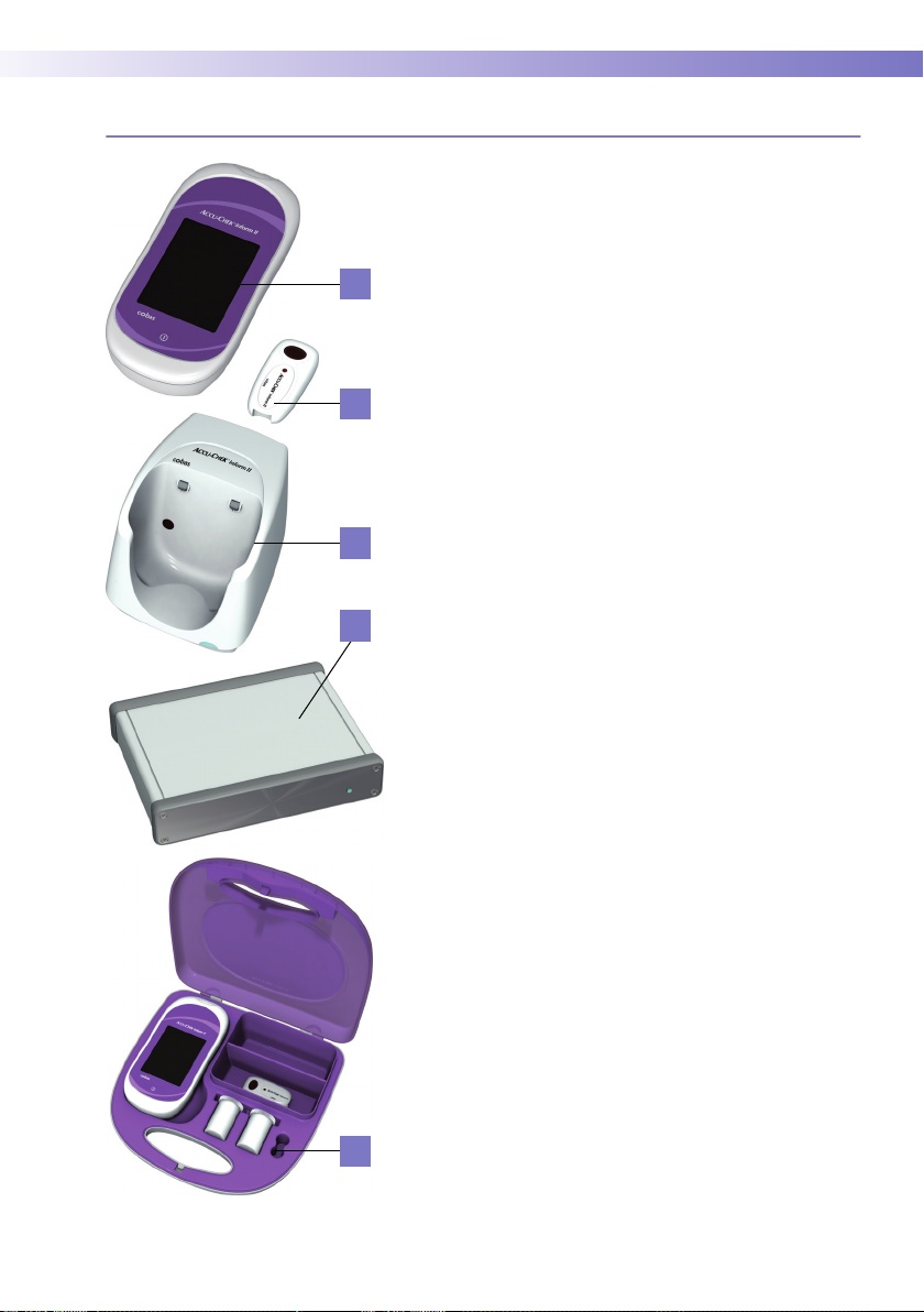
1.3 System components
A
B
C
D
Introduction • 1
The Accu-Chek Inform II system includes the following
components and accessories:
A Meter
B Code key reader
C Base unit (power supply not shown)
D Accu-Chek Inform II Base Unit Hub (power supply
not shown)
E Accessory box (shown with consumables, not
included)
The meter can be configured by two different methods:
1 Configuration via the Setup function on the meter
(see Chapter 9)
2 Configuration via data management system
Note: Not all options can be configured using the Setup
function on the meter.
The meter performs the following tasks within the system:
■ Serves as the primary operator interface through
the touchscreen and on/off button
■ Performs glucose tests
■ Scans barcodes
1
(test strip lots, controls, patient
and operator IDs) in a variety of supported formats
■ Displays test results from patient tests and control
tests
■ Transfers stored data to the data management
system via wireless communication (WLAN,
optional) or the base unit (LAN)
E
1. Barcodes on control solutions may not be available in all
countries. A list of supported barcode symbologies can be
found in Appendix A.2.
27
Page 28
1 • Introduction
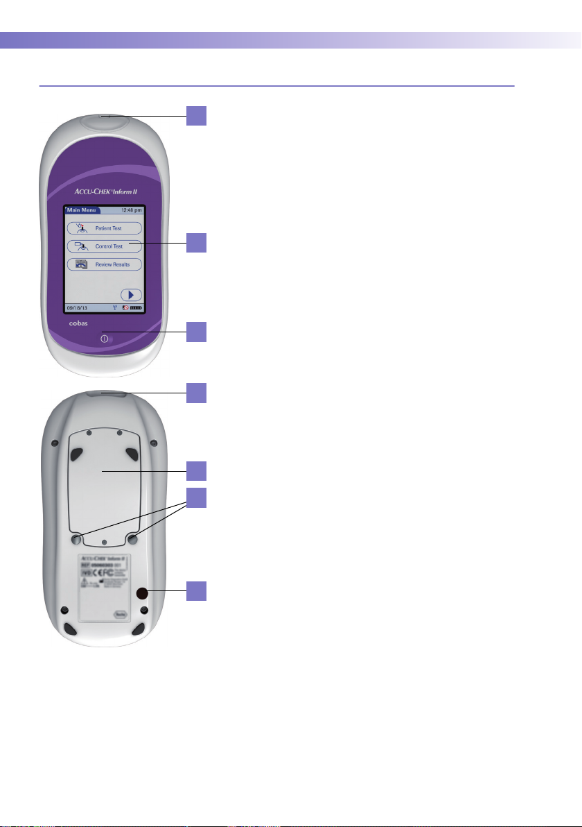
1.4 Overview of the meter
1
2
3
4
The meter has the following elements:
1 Test strip port
Insert the test strip here.
2 Touchscreen
(touch-sensitive display)
This screen allows you to perform patient tests, perform controls tests, and review results. To select
any of these functions, simply touch the button on
the screen.
3 On/Off button
Press this button to power the meter on or off.
4 Barcode scanner
The integrated barcode scanner can be used to
read operator and patient IDs.
5 Battery compartment cover
Remove to insert the battery pack.
6 Charging contacts
These contacts are used to charge the battery pack
when the meter is in the base unit.
28
7 Infrared window
5
6
7
Facilitates data communication with code key
reader and base unit.
Page 29
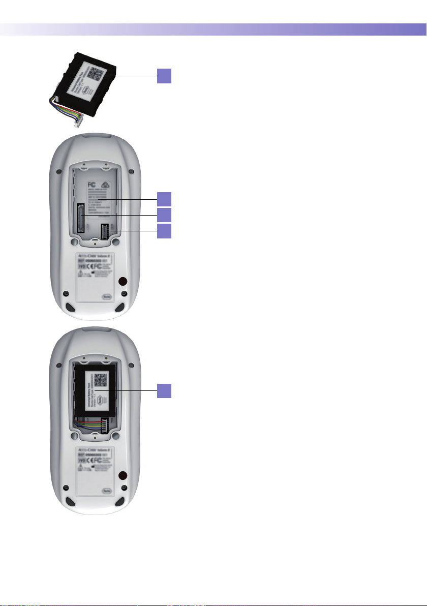
8
9
10
11
Introduction • 1
8 Battery pack
Powers the device.
9 Wireless LAN label
If the meter supports wireless connectivity: This
label displays registration numbers that are specific
to the meter RF hardware.
10 Interface
(For manufacturer’s use only.)
11 Battery pack connector socket
Connect battery pack here.
8
29
Page 30

1 • Introduction
1.5 Overview of the code key reader
Test strip vials include a code key.1 This code key is read
by the code key reader and the data is sent to the meter.
14
For additional information about the code key reader, see
Chapter 6.
13
12
The code key reader has the following elements:
12 Code key slot
13 LED (green) for displaying status
14 Infrared window for transmitting the code file to the
meter
Do not replace code keys while the code key reader is
still flashing. If the green LED status light is still flashing, the code key reader will continue to transmit the
previously loaded code file and ignore the code file on
the newly inserted code key. You may get an error
message on the meter.
30
1. The code key is also frequently referred to as a code chip.
The terms are synonymous.
Page 31

1.6 Overview of the base unit
Introduction • 1
To provide flexibility in line with customer requirements,
two versions of the base unit are available.
20 21 18
15
16
17
19
■ The Accu-Chek Inform II Base Unit
■ The Accu-Chek Inform II Base Unit Light
Both versions of the base unit can:
■ charge the meter battery pack.
In addition, the Accu-Chek Inform II Base Unit also
supports:
■ communication with a data management system.
■ communication with a computer.
1
Both versions of the base unit have the following elements:
15 Charging contacts
16 Infrared window for communication with the meter
17 Status LED (lights up when power is connected):
– Lights up red: Power supply is connected, applica-
tion is starting up (Accu-Chek Inform II Base Unit
only)
– Lights up green: Ready
– Flashes red: Error
– Lights up blue: Configuration mode (Accu-Chek
Inform II Base Unit only)
17
18 Jack for the power supply unit provided
19 Removable mount for wall installation
The Accu-Chek Inform II Base Unit has the following
additional elements:
20 Network connection — LAN, Ethernet (RJ45)
21 USB connection
1. The Accu-Chek Inform II Base Unit Light can support
communication with a data management system only
when used together with the Accu-Chek Inform II Base
Unit Hub.
31
Page 32

1 • Introduction
Electrical connections are located on the back of the base
unit (for a better view the removable wall mount is shown
as transparent).
For instructions on connecting the base unit, see
Chapter 9.
1.7 Overview of the Accu-Chek Inform II Base Unit Hub
The Accu-Chek Inform II Base Unit Hub is able to connect up to 4 Accu-Chek Inform II Base Units Light (RJ25)
and supports communication to a data management
system via Ethernet (RJ45).
The hub also provides power for the Accu-Chek Inform II
Base Unit Light. When connected to a hub an Accu-Chek
Inform II Base Unit Light does not require a separate
power supply. The LED colors of the hub are the same as
17
for the Accu-Chek Inform II Base Unit Light.
17 Status LED (lights up when power is connected)
18 Jack for the power supply unit provided
20 Network connection — LAN, Ethernet (RJ45)
32
20 18
2221
21 USB connection
22 Connections for up to 4 Accu-Chek Inform II Base
Units Light (RJ25, data transfer, and power)
Page 33

1.8 Overview of the accessory box
The accessory box provides an area for storing and transporting consumables needed for performing point-ofcare blood glucose tests.
1.9 Reagents and consumables
You need the following reagents to perform patient tests
and glucose control tests:
Introduction • 1
■ Accu-Chek Inform II Test Strips
■ Accu-Chek Performa Control Solutions
■ Accu-Chek Linearity Kit (if required by your facility
guidelines)
Your facility provides additional consumables such as
blood collection supplies. Observe the current rules and
safety guidelines for collecting and handling blood
samples.
33
Page 34

1 • Introduction
1.10 Instructions for initial setup
The meter must be configured prior to initial use. During
this setup, the following parameters are configured:
■ Date and time format
■ Input mode for Patient ID
■ Input mode for Operator ID
■ Glucose controls: Type and schedule
■ Results screen for glucose control
■ Comments for entry after a test
■ Settings for data transfer
You can perform these settings on a limited basis directly
in the Setup Menu of the meter. For more information
about configuration using the Setup Menu, see
Chapter 9, as well as Appendix A. In addition to this
option, the meter can be configured using a data management system. Suitable data management systems
provide a range of functions for configuring the meter
that go beyond what is possible with the meter-based
configuration feature.
34
For questions about using data management systems,
contact your Roche representative (see Chapter 12).
To ensure standardized configuration within a facility,
the meter-based Setup Menu may be disabled.
Page 35

Powering Up and Entering an Operator ID • 2
2 Powering Up and Entering an Operator ID
2.1 Powering up the meter
1 Press and release the On/Off button . The meter
is now on.
2 The Power Up screen appears.
3 Check in the Power Up screen whether the date
(lower left) and time (upper right) are displayed
correctly. If necessary, refer to the instructions for
updating these settings in Chapter 9.
Power Up 12:48 pm
Performing self-checks...
Contrast
09/18/13
■ If during self-check an error is detected, the appro-
priate error message appears on screen.
■ If the QC Lockout feature is enabled and glucose
control is required, a corresponding message is
displayed.
■ The battery icon shows the current battery level.
A completely filled icon indicates a fully
charged battery, and a partial charge is displayed
as a partially filled battery icon . If the battery
is nearly empty, the battery icon turns red .
35
Page 36

2 • Powering Up and Entering an Operator ID
Adjusting the display Using the Display options, you can adjust the display con-
trast to the ambient light conditions.
Display
Lighter Darker
09/18/13
12:48 pm
Enabling/disabling wireless connectivity
WARNING
1 In the Power Up screen, touch Contrast. The Display
screen appears.
2 Touch or to make the display lighter or
darker.
3 Touch to confirm the setting.
After 30 seconds without any activity (e.g., without a
screen touch) the meter automatically dims the display backlight to conserve energy (“Low Power
Mode”).
If the meter supports wireless connectivity, you can temporarily enable or disable this functionality as required.
Wireless connectivity is automatically reactivated the next
time you power on the meter. You can then disable it
again temporarily, if required.
If you suspect that the RF emissions of wireless communication are harming the patient or affecting other
devices, you should carefully reassess the appropriateness of continued use of the WLAN functionality of the
Accu-Chek Inform II system using the guidelines of your
facility.
36
Page 37

Powering Up and Entering an Operator ID • 2
Power Up 12:48 pm
Contrast
09/18/13
Power Up 12:48 pm
Contrast
09/18/13
If wireless connectivity is activated, the (RF OFF)
icon is displayed as a button in the Power Up screen.
■ To temporarily disable the wireless network con-
nection, touch (RF OFF) in the Power Up
screen. The icon then changes to (RF ON).
■ To temporarily enable the wireless network con-
nection, touch (RF ON) in the Power Up
screen. The icon then changes to (RF OFF).
The RF ON/RF OFF button always displays the option you
currently have. The current communication status is displayed in the status bar (bottom line) of the display in all
menus and screens.
■ The icon is displayed, if wireless connectivity is
enabled.
■ The icon is displayed if the last attempt to com-
municate with the data management system was
successful and was terminated according to the
communication protocol.
■ The icon is displayed if the last attempt to
communicate with the data management system
was not successful or was unintentionally terminated. If this icon persists, contact your system
administrator. Ignoring this information may lead to
a Download Lockout (if configured, see page 41).
Closing startup Once you have completed all the necessary changes,
■ touch to proceed to the screen used to enter
the operator ID, or
■ wait 5 seconds and the meter automatically pro-
ceeds to the screen used to enter the operator ID.
37
Page 38

2 • Powering Up and Entering an Operator ID
2.2 Entering the operator ID
How and when an operator ID is entered and if a password is required, depends on the configuration of the
system. It is also, for example, possible to require the
operator ID only when starting control tests. In general,
the system can manage and check operator IDs as well
as make additional functions ID-dependent.
Main Menu
Maria S.
09/18/13
12:48 pm
Patient Test
Control Test
Review Results
If an operator name matching the entered operator ID is
available on the meter, this name will be displayed in the
Main Menu (shown here as “Maria S.”).
There are a number of options for entering operator IDs
and these depend on the configuration of the system:
■ Via barcode scanner
■ Manually or optionally via barcode scanner
1
only
Operator IDs can consist of up to 20 alphanumeric
characters.
Alphanumeric characters are any combination of
A - Z and 0 - 9, additionally “.” (period), or “-”
(hyphen) may be used. See also page 40.
Barcode masking can be used to eliminate any characters not belonging to the Operator ID. See information on “Operator and patient ID barcode masks” on
page 172.
38
1. A list of supported barcode symbologies can be found in
Appendix A.2.
Page 39

Powering Up and Entering an Operator ID • 2
Entering an operator ID with barcode scanner
Operator ID
123
456
789
09/18/13
12:48 pm
A-O0
When the screen for entering the operator ID is
displayed:
1 Press and release . The button now appears
with a black background (during the scan).
2 Hold the meter so that the window of the barcode
scanner is approx. 10-20 cm (4-8 in) above the barcode you wish to read.
The meter beeps once the barcode has been read successfully. The barcode information appears in the operator ID field. The barcode scanner turns off after 10
seconds, if a barcode is not scanned.
39
Page 40

2 • Powering Up and Entering an Operator ID
Entering the operator ID manually
Operator ID
123
456
789
09/18/13
12:48 pm
A-O0
When the screen for entering the operator ID is
displayed:
Operator ID
MARIA
ABCDE
FGHI J
KLMNO
09/18/13
12:48 pm
P-Z123
Operator ID
MARIA S.
PQRST
UVWXY
Z.
123 A-O
09/18/13
12:48 pm
-
1 Touch the letters or numbers to enter the ID.
2 Use the following buttons to toggle between ranges
of characters:
A-O
– for letters A-O
P-Z
– for letters P-Z
123
– for numbers 0-9
3 Touch to backspace and delete a character
entered incorrectly. Touch to delete the whole
entry. Touch to enter a space.
4 Touch to confirm.
If the operator ID you have entered is not valid (or the
operator is not stored in the meter), an error message is
displayed. Confirming the message allows you to enter
the ID again.
Entering a password Once the operator ID has been entered correctly, a
screen for entering a password may appear (if configured). Enter the password in the same manner as
described above for the operator ID.
Once all entries are complete, the Main Menu appears.
40
Page 41

Patient Glucose Testing • 3
3 Patient Glucose Testing
3.1 Information regarding blood glucose testing
Preparing to test The following requirements must be met before you can
perform a test:
Power Up
QC Due: Immediately
Contrast
09/18/13
12:48 pm
■ The Accu-Chek Inform II test strips are available.
■ The code file for the test strip lot in use must be
stored in the meter (see Chapter 6).
■ An operator ID must be entered (with password, if
required), if the meter is configured for login.
■ Glucose control tests specified in the system con-
figuration must be run and completed successfully
before running patient tests. Information whether
glucose control tests are necessary is displayed in
the Power Up screen.
■ If configured, the meter may require downloading
stored data to the data management system within
defined time intervals. If such a download (either
via WLAN or by docking the meter in a base unit)
does not happen within the specified time, the
meter is locked (Download Lockout) and cannot be
used for testing.
41
Page 42

3 • Patient Glucose Testing
If a glucose control test is shown as required, patient glucose testing cannot be performed until the controls are
run successfully.
Depending on how your meter is configured (see
page 121), QC Lockout occurs when
■ patient testing is attempted and controls have not
been run in the time interval or frequency established by your facility.
■ controls have been run but the control values
were not in range.
■ a test strip lot other than the “current” lot is
selected.
■ new software has been installed.
For emergencies, STAT (Short TurnAround Time) tests
can be configured in the meter. This option allows the
meter to perform a limited number of patient glucose
tests, if circumstances require, despite the meter being in
QC Lockout or Download Lockout (see page 68).
■ Observe the applicable regulations and directives
for hygiene and safety when collecting blood
samples.
■ Observe the applicable regulations and directives
for disposing of potentially infectious samples and
materials.
3.2 Performing a patient glucose test
Overview of test procedure A patient glucose test comprises the following steps:
■ Enter the patient ID. This can be done either man-
ually or by using the barcode scanner.
■ Confirm that the test strip lot matches the test strips
in use (if configured).
■ Perform the test.
■ Optionally a test may be categorized as an
Observed Test Sequence (see page 203).
42
Page 43

Patient Glucose Testing • 3
As mentioned previously, the following steps must be
completed already:
1 The meter is switched on.
2 You have entered your operator ID.
3 You have completed login by selecting and
the Main Menu screen is displayed.
Entering or selecting the patient IDAfter preparing the meter as described, you can proceed
to the steps directly related to testing:
Main Menu
09/18/13
12:48 pm
Patient Test
Control Test
Review Results
Patient ID
123
456
789
09/18/13
12:48 pm
A-O0
Patient ID
123456789
Patient Confi rmation
ABCDE
D-503: Patient ID:
123456789
F GHI J
Name:
Mary-Jane Miller
DOB: 12/03/56
KLMNO
Is this correct?
P-Z 123
09/18/13
1 From the Main Menu screen touch Patient Test.
2 Enter or select the Patient ID as described on the
following pages.
3 If the function Patient Confirmation is enabled,
verify and confirm the displayed patient information, after you entered or selected the ID.
12:48 pm
43
Page 44

3 • Patient Glucose Testing
You now have three different options, depending on
setup, for assigning the subsequent test to a patient.
The patient ID function can be configured by your
system administrator to:
■ Enter any combination of up to 20 alphanumeric
characters, with specified minimum and maxi-
mum lengths.
Alphanumeric characters are any combination of
A - Z and 0 - 9, additionally “.” (period), or “-”
(hyphen) may be used.
■ Enter patient ID via barcode scanner.
■ Select a patient from a list.
2
1
The following options are available for validating
patient IDs:
■ Manual entries can be validated based on an
downloaded list.
■ Confirmation of patient name, date of birth, and ID
can be required.
■ Barcode masking can be used to eliminate any
2
characters not belonging to the Patient ID. See
information on “Operator and patient ID barcode
masks” on page 172.
44
1. A list of supported barcode symbologies can be found in
Appendix A.2.
2. Depending on the meter configuration, this feature may
be disabled.
Page 45

Patient Glucose Testing • 3
Entering the patient ID manually Use the displayed keypad to enter the patient ID. You can
select characters in the same manner as when entering
an operator ID.
Patient ID
ABCDE
FGHI J
KLMNO
09/18/13
12:48 pm
P-Z123
Selecting the patient ID from a list
Patient ID
Keyboard
Name: James Doe
ID: 2222222222
Name: Jane Doe
ID: 3333333333
Name: Jenny Doe
ID: 4444444444
Name: John Doe
ID: 5555555555
12:48 pm
1 Touch the letters or numbers to enter the ID.
2 Use the following buttons to toggle between ranges
of characters:
A-O
– for letters A-O
P-Z
– for letters P-Z
123
– for numbers 0-9
3 Touch to backspace and delete a character
entered incorrectly. Touch to delete the whole
entry. Touch to enter a space.
4 Touch to confirm, or touch to cancel this
procedure and return to the Main Menu.
If the patient ID you have entered is not valid (or the
patient is not found in the downloaded list), an error message is displayed. Confirming the message allows you to
enter the ID again.
Choose the patient ID from a list
1
, if a list has been down-
loaded to the meter (from the data management system).
1 Touch or to scroll up or down in the list.
If one of the buttons is hidden, you have reached the top
or bottom of the list.
2 Touch the desired entry to select a patient, or touch
to cancel this procedure and return to the
Main Menu.
09/18/13
1. Depending on the meter configuration, this feature may
be disabled.
45
Page 46

3 • Patient Glucose Testing
Entering a patient ID with barcode scanner
Patient ID
ABCDE
FGHI J
KLMNO
09/18/13
12:48 pm
Patient ID
Keyboard
Name: James Doe
ID: 2222222222
P-Z123
Name: Jane Doe
ID: 3333333333
Name: Jenny Doe
ID: 4444444444
Name: John Doe
ID: 5555555555
09/18/13
When the screen for entering the patient ID is displayed:
12:48 pm
1 Press and release . The button now appears
with a black background (during the scan).
2 Hold the meter so that the window of the barcode
scanner is approx. 10-20 cm (4-8 in) above the barcode you wish to read.
The meter beeps once the barcode has been read successfully. The barcode information appears in the patient
ID field. The barcode scanner turns off after 10 seconds, if
a barcode is not scanned.
46
Page 47

Patient Glucose Testing • 3
Confirming or selecting the test strip lot
Patient Test
Patient 123456789
Use Strip Lot
123456?
09/18/13
Strip Lots
09/18/13
12:48 pm
12:48 pm
545794
344789
545777
344654
Once you have entered and confirmed the patient ID, you
are asked to choose the lot number for the test strips.
Compare the number displayed by the meter to the
number on the label of the test strip vial.
1 Select the lot number as follows:
■ If you want to use the preselected lot number dis-
played by the meter, touch to confirm.
■ To use a different lot number than the one dis-
played, touch to display a list of stored lot
numbers. Select the desired lot number from the
list.
■ To read the lot number from the test strip vial via
barcode scanner, press and release . Follow
the instructions for scanning IDs (see note below).
2 Touch to confirm the selected or scanned lot
number.
The meter can be configured so that manual
confirmation is not necessary. In this setup, only the
lot number is displayed. Additional options are not
available.
The meter can be configured so that lot numbers are
entered via barcode scanner only (see note below).
For additional information about storing lot numbers for
test strips, see page 73.
Note: Barcodes on control solutions may not be available in all countries. In this case either
■ manually enter the lot number each time
(recommended),
■ pick a previously entered lot number from the list,
or
■ configure the meter to only display the lot number
(without confirmation by the operator).
47
Page 48

3 • Patient Glucose Testing
Inserting test strips After confirming the test strip lot, a flashing green arrow
appears on screen and prompts you to insert the test
strip.
Patient Test
Patient 123456789
ot 545794
Strip L
09/18/13
Patient Test
Patient 123456789
ot 545794
Strip L
09/18/13
12:48 pm
12:48 pm
1 Remove the test strip from the test strip vial and
close the vial with the cap.
2 Hold the test strip so the lettering “ACCU-CHEK” is
facing upward.
3 Slide the test strip into the test strip port as far as it
goes in the direction indicated by the arrows on the
test strip.
The meter beeps. The hourglass icon appears and indicates that the meter is checking the test strip. Do not
apply blood while it is displayed.
48
Page 49

Patient Glucose Testing • 3
Obtaining a blood sample Prepare the selected blood collection site and obtain
blood from the patient per facility policy.
Recommendations for the collection of capillary
blood
If no facility policy exists for obtaining capillary blood, the
patient's hands (or heel in the case of small children)
should be washed with warm water and soap, and then
dried thoroughly. If you are using alcohol wipes or other
disinfectants when obtaining capillary blood, the patient's
skin must be completely dry before you lance the site to
obtain blood.
We recommend obtaining the capillary blood sample
from the side of the fingertip as this part is the least
sensitive to pain.
Potential risk of incorrect results due to residues on
skin
WARNING
■ Traces of food on the fingers or fatty residues from
hand cremes or soap products may contaminate
the sample and lead to incorrect results. Wash the
puncture site thoroughly and rinse with plenty of
water.
■ Residues of water or disinfectant on the skin can
dilute the drop of blood and lead to incorrect
results. After you have washed and disinfected the
site, ensure that the patient's skin is completely dry
before lancing the site to obtain a capillary blood
sample.
Use an auto-disabling single-use lancing device for each
patient. The lancing device must be intended for use by
healthcare professionals in a multiple patient setting.
Follow the manufacturer's instructions for use.
49
Page 50

3 • Patient Glucose Testing
Applying a blood sample Once the meter has checked the test strip, the hourglass
icon disappears and you are prompted to apply a blood
sample.
Patient Test
Patient 123456789
ot 545794
Strip L
09/18/13
12:48 pm
When applying the sample, position the meter so that
the test strip port is always higher or on the same level
as the blood drop. This prevents any excess blood
from flowing down the strip and entering the meter.
50
1 Wait until the flashing drop appears in the display
before applying the blood. The meter beeps.
2 Apply the drop of blood to the front edge (yellow
dosing area) of the test strip. Blood is pulled into
the test strip by capillary action.
Do not apply the blood to the top of the strip. Blood
on top of the test strip is not available for testing
because it will not be pulled into the strip.
Once a sufficient blood sample has been detected, the
meter beeps and the measurement begins.
Page 51

Patient Glucose Testing • 3
Results screen The hourglass icon indicates the test is running. When
the test is completed and the result is ready, the meter
beeps again.
Patient Test
Patient 123456789
ot 545794
Strip L
09/18/13
12:48 pm
Patient Test
Patient 123456789
Date 09/18/13 12:48 pm
mmol/L
8.3
Range
09/18/13
12:48 pm
Patient Test
Patient 123456789
te 09/18/13 12:48 pm
Da
150
I-502:
3.9-11.1 mmol/L
Critical Range:
2.2-16.7 mmol/L
Repor
table Range:
0.6-33.3 mmol/L
09/18/13
12:48 pm
Range
Normal Range:
L22
When the result is displayed, a message or warning may
also appear (depending on system configuration) notifying you if the result exceeds the specified limit values.
Additionally, a red flashing arrow next to the test result
indicates that a result is out of range.
: the value is above the normal/critical upper range.
: the value is below the normal/critical lower range.
These limit values define ranges that can either be configured individually by the system administrator in line
with facility guidelines, or are the (technical) limits of the
system. The characteristics of these ranges are explained
on the following page.
The results screen contains a button that changes its
name based on the result (Range or Out of ... Range).
Touch this button to display the configured limit values.
51
Page 52

3 • Patient Glucose Testing
Patient Test
Patient 123456789
Date 09/18/13 12:48 pm
12.2
Out of Normal Range
09/18/13
mmol/L
12:48 pm
Patient Test
Patient 123456789
Date 09/18/13 12:48 pm
mmol/L
1.9
Out of Critical Range
Patient Test
Patient 123456789
Date 09/18/13 12:48 pm
09/18/13
CR LO
Out of Critical Range
09/18/13
■ The System Measurement Range refers to the
12:48 pm
12:48 pm
Patient Test
Patient 123456789
Date 09/18/13 12:48 pm
RR HI
Out of Reportable Range
09/18/13
12:48 pm
Patient Test
Patient 123456789
Date 09/18/13 12:48 pm
16.9
Out of Critical Range
09/18/13
mmol/L
measurement range of the system itself (strips and
meter) and is the only range which cannot be configured. With Accu-Chek Inform II test strips this
fixed range is 10 to 600 mg/dL (0.6 to 33.3 mmol/L).
If a result falls outside this range, the message HI or
LO appears, i.e., the result cannot be quantified
properly.
12:48 pm
52
■ Glucose results above or below the Reportable
Range, as defined by the institution or local regulatory body, are above the highest or below the
lowest numerical results to be reported. Results
outside this range must not be used for intervention
decisions.
■ Glucose results above or below the Critical Range,
as defined by the institution, require immediate
action as defined by hospital policy.
■ Glucose results within the Normal Range, as
defined by the institution, are considered normal
and require no therapeutic action.
Page 53

Patient Glucose Testing • 3
1
The following messages
may appear in instead of a
numeric test result:
■ CR LO (below the Critical Range threshold, but
within the Reportable Range)
■ CR HI (above the Critical Range threshold, but
within the Reportable Range)
■ RR LO (below the Reportable Range threshold, but
within the System Measurement Range)
■ RR HI (above the Reportable Range threshold, but
within the System Measurement Range)
■ LO (below the System Measurement Range)
■ HI (above the System Measurement Range)
For test results that lie outside the critical or reportable range, a message (up to 100 characters in length)
can be configured during setup. This message is then
displayed with the corresponding test results.
Instructions on how to add comments are provided in the
following section.
1. Results that are below or above the Critical Range threshold, but within the Reportable Range can be configured to
display as either numeric results or as CR LO or CR HI. All
other results exceeding specified limit values will always
be displayed as RR LO, RR HI, LO, or HI.
53
Page 54

3 • Patient Glucose Testing
If comments are not set as required and you do not wish
to add a comment to the test result, touch to return
to the Main Menu.
Test results are also saved when the meter is powered
off in the results screen or when it powers off automatically.
Remove the test strip and dispose of it in accordance with
applicable regulations and directives for disposal of
potentially infectious samples and materials.
Adding comments You can add up to three comments to a test result.
Comments can provide, for example, additional
information about the test conditions or the patient.
Of these three comments only one can be a custom
comment; the others can be selected from the predefined comments list.
The meter can be configured so that comments are
always required, required depending on the result range,
optional, or disabled. You can call up the function for
adding comments directly in the results screen. If comments are set as required, the meter will not accept an
empty comment field.
54
Page 55

Patient Glucose Testing • 3
Patient Test
Patient 123456789
Date 09/18/13 12:48 pm
12.2
Out of Normal Range
09/18/13
mmol/L
12:48 pm
Add Comments
New Strip Lot
Doctor Notifi ed
Will Repea
RN Notifi ed
09/18/13
12:48 pm
t Test
Patient Test
Patient 123456789
Date 09/18/13 12:48 pm
12.2
Out of Normal Range
New Strip Lot
Doctor Notifi ed
Will Repeat Test
09/18/13
mmol/L
12:48 pm
To add comments:
1 In the Patient Test screen, touch .
2 Select up to three desired predefined comment(s)
from the display list (if configured) or touch to
enter up to one custom comment (if custom commenting is enabled). Use the keypad (as with login)
to enter your comment(s).
3 Once you have selected the desired comment(s),
touch to return to the results screen.
4 Touch to return to the Main Menu.
55
Page 56

3 • Patient Glucose Testing
Test results are also saved when the meter is powered
off in the results screen or automatically powers off
after 10 minutes of inactivity (no screen touches). See
“Automatic power-off” on page 19.
Remove the test strip and dispose of it in accordance with
applicable regulations and directives for disposal of
potentially infectious samples and materials.
56
Page 57

4 Glucose Control Testing
4.1 Information regarding glucose control tests
Observe the applicable regulations and directives of the
responsible regulatory agencies when performing glucose control tests. See also safety message “Allergy or
injury caused by reagents and other working solutions”
on page 18.
Accurately testing known levels of glucose ensures that
the system and your technique used in testing give accurate results on patient tests. Glucose control solutions
have defined (known) values. The results for these solutions must first fall within a certain acceptable range in
order to allow valid patient testing.
The system may be configured to require in-range glucose control testing before patient testing is allowed. This
is called QC Lockout, and the system actually prevents
patient and proficiency testing when the control results
are not within the accepted range.
Glucose Control Testing • 4
57
Page 58

4 • Glucose Control Testing
Glucose control testing intervals Intervals between running glucose control tests are
determined by your facility. These intervals are entered
when the system is configured. At the end of the specified interval (or after a specific event such as starting to
test with a new test strip lot), a warning is displayed when
the meter is switched on and when the Glucose Test
function is selected.
Power Up
QC Due: Immediately
Contrast
09/18/13
12:48 pm
Glucose control tests should be run in the following circumstances:
■ Before using the meter for patient testing the first
time
■ At the glucose control intervals established by your
facility
■ When using a new test strip vial for the first time
■ When using a new test strip lot for the first time
(and as a result a new test strip code)
■ If a test strip vial was left open
■ If questionable test results are displayed repeatedly
■ If you wish to test the performance of the system
In addition, the following events can be specified during
setup as a reason for a glucose control test:
■ If a previous control test is out of range
■ If glucose control tests were not run at the proper
intervals
58
Page 59

Glucose Control Testing • 4
If a glucose control test is required (as shown in the illustration on the left), you will not be able to test blood glucose until the controls have been run successfully. For
emergencies, STAT tests can be configured in the meter.
This option allows the meter to perform a limited number
of blood glucose tests, if circumstances require, despite
the meter being in QC Lockout (see page 68).
Information stored during glucose control testing
The following information is stored for every glucose control test using control solution:
■ Glucose control test result
■ Lot number of the control solution
■ Operator ID (if configured)
■ Level of control solution (L1 or L2)
■ Lot number of the test strips
■ Time and date of test
■ Comments (if applicable)
■ Out of range measurements
59
Page 60

4 • Glucose Control Testing
Control solutions For blood glucose test strips, control solutions have two
levels:
■ Level 1 (L1): Lo (low values in test results)
■ Level 2 (L2): Hi (high values in test results)
Preparing to run a glucose control test
Aside from special preparations (see the following section), a glucose control test is run in the same manner as
a patient test:
■ At least one code file for test strips must be stored
in the meter and match the lot number of the test
strips used (see Chapter 6).
■ The proper test strips must be available.
■ An operator ID must be entered (with password, if
applicable), if the meter is configured for login.
60
Page 61

Glucose Control Testing • 4
4.2 Performing glucose control tests
Overview of test procedure A glucose control test using control solution comprises
the following steps:
■ Select the desired level of control solution for the
test.
■ Check the lot number of the control solution.
■ Check the lot number of the test strips.
■ Perform the test with the control solution.
The result must fall within the specified range (as shown
on the label of the test strip vial or defined per configuration) for the control test to be completed successfully.
Patient tests can now be performed (again).
61
Page 62

4 • Glucose Control Testing
Starting a glucose control test After preparing the meter as described, you can proceed
to the steps directly related to control testing:
Main Menu
09/18/13
12:48 pm
Patient Test
Control Test
Review Results
Control Test
Level 1 (Lo)
Level 2 (Hi)
09/18/13
12:48 pm
Required
1 From the Main Menu screen touch Control Test.
In the Control Test screen, the levels available for the
control solution are displayed. To the right of the buttons,
the word Required identifies the level at which a glucose
control test must be run to remove QC Lockout.
2 Touch Level 1 (Lo) or Level 2 (Hi) to select the level
for the following test. In the example above, Level 2
(Hi) is marked.
62
Page 63

Glucose Control Testing • 4
Confirming or selecting the lot number for control solutions
Control Test
Control L2 (Hi)
Use Control L
123456?
09/18/13
Control Lot
123
456
789
12:48 pm
ot
12:48 pm
0
Once you have selected the level, you are asked to confirm or enter the lot number of the control solution. Compare the number displayed by the meter to the number on
the label of the control solution.
1 Select the lot number as follows:
■ If you want to use the preselected number dis-
played by the meter, touch to confirm.
■ If you want to use a different number than the lot
number displayed, touch to open the keypad
and enter the number manually, or
■ To read the lot number from the control solution
bottle via barcode scanner, press and release
. Follow the instructions for scanning IDs (see
page 39). *
2 Touch to confirm the selected test strip lot
number.
The meter can be configured so that manual confirmation is not necessary. In this setup, only the lot
number is displayed. Additional options are not available.
09/18/13
The meter can be configured so that lot numbers are
entered via barcode scanner only. *
For additional information about storing lot numbers for
control solutions, see page 80.
* Barcodes on control solutions may not be available in all
countries (see page 47).
63
Page 64

4 • Glucose Control Testing
Confirming or selecting the test strip lot
Control Test
Control L2 (Hi) 123456
Use Strip L
123456?
09/18/13
Strip Lots
12:48 pm
ot
12:48 pm
545794
344789
545777
344654
Once you have entered and confirmed the lot number of
the control solution, you are asked to choose the lot
number for the test strips. Compare the number displayed by the meter to the number on the label of the test
strip vial.
1 Select the lot number as follows:
■ To read the lot number from the test strip vial via
barcode scanner, press and release . Follow
the instructions for scanning IDs. *
■ If you want to use the preselected lot number dis-
played by the meter, touch to confirm.
■ To use a different lot number than the one dis-
played, touch to display a list of stored lot
numbers. Select the desired lot number from the
list.
2 Touch to confirm the selected test strip lot
number.
The meter can be configured so that manual
confirmation is not necessary. In this setup, only the
lot number is displayed. Additional options are not
available.
09/18/13
64
The meter can be configured so that lot numbers are
entered via barcode scanner only. *
The meter can be configured so that lot numbers can
only be selected from a list.
For additional information about storing lot numbers for
test strips, see page 73.
* Barcodes on control solutions may not be available in all
countries (see page 47).
Page 65

Glucose Control Testing • 4
Inserting test strips After confirming the test strip lot, a flashing green arrow
appears on screen and prompts you to insert the test
strip.
Control Test
Control L2 (Hi) 123456
ot 545794
Strip L
09/18/13
Control Test
Control L2 (Hi) 123456
ot 545794
Strip L
09/18/13
12:48 pm
12:48 pm
1 Remove the test strip from the test strip vial and
close the vial with the cap.
2 Hold the test strip so the lettering “ACCU-CHEK” is
facing upward.
3 Slide the test strip into the test strip port as far as it
goes in the direction indicated by the arrows on the
test strip.
The meter beeps. The hourglass icon appears and indicates that the meter is checking the test strip. Do not
apply control solution while it is displayed.
65
Page 66

4 • Glucose Control Testing
Applying the control solution Once the meter has checked the test strip, the hourglass
icon disappears and you are prompted to apply control
solution.
Control Test
Control L2 (Hi) 123456
ot 545794
Strip L
09/18/13
12:48 pm
When applying the control solution, position the meter
so that the test strip port is always higher or on the
same level as the control solution. This prevents any
excess solution from flowing down the strip and
entering the meter.
66
1 Wait until the flashing drop appears in the display
before applying the control solution. The meter
beeps.
2 Apply a drop of glucose control solution to the
front edge of the test strip. Do not apply the control solution to the top of the strip.
The control solution is pulled into the test strip by
capillary action.
Once sufficient control solution has been detected, the
meter beeps and the measurement begins.
Page 67

Glucose Control Testing • 4
Results screen The hourglass icon indicates the test is running. When
the test is completed and the result is ready, the meter
beeps again.
Control Test
Control L2 (Hi) 123456
Da
te 09/18/13 12:48 pm
17.1
09/18/13
mmol/L
Range
12:48 pm
Control Test
Control L2 (Hi) 123456
Date 09/18/13 12:48 pm
PASS
09/18/13
12:48 pm
Control Test
Control L2 (Hi) 123456
te 09/18/13 12:48 pm
Da
FAIL
09/18/13
12:48 pm
Depending on configuration, the result is displayed either
as a value or only as a qualitative result Pass or Fail. Your
system may be configured to disallow further testing until
all the required glucose control levels are successfully
run (QC Lockout).
When the results are displayed as a value, the results
screen contains a button that changes its name based on
the result (Range or Out of … Range). Touch this button
to display the minimum and maximum target values for
the control levels.
You can add comments to a test result (as with blood
glucose tests) (see page 54).
If you do not wish to add a comment to the test result,
touch to continue to the next level of the control
test, if necessary, or to return to the Main Menu.
Test results are also saved when the meter is powered
off in the results screen or when it automatically
powers off.
Remove the test strip and dispose of it in accordance with
applicable regulations and directives.
67
Page 68

4 • Glucose Control Testing
Performing a STAT test The meter can be configured to allow a STAT patient glu-
cose test to be run even if the meter is in QC Lockout or
Download Lockout. This option is to be used in situations
with critical patients. The system administrator can allow
control tests to be delayed one to nine times.
Patient Test Menu
Glucose Test
QC Lockout
D-513: Warning! Glucose
control is due. Required
Controls must be run in
order to proceed. 9 ST
test(s) available.
Run QC Run STAT
09/18/13
12:48 pm
AT
Run STAT appears in the QC Lockout warning box under
the following conditions:
■ You are successfully logged in and have selected
Patient Test from the Main Menu.
■ A glucose control test is required (due to specified
control intervals or other conditions).
■ The administrator has enabled the STAT test option
during setup.
■ The number of STAT tests available has not been
exceeded.
If these conditions are fulfilled, two buttons appear in the
warning message that allow you to choose the next step:
■ Touch Run QC to run the required control test
instead of a patient test.
■ Touch Run STAT to perform a patient test even if a
glucose control test is required. The status as STAT
test is stored with the data record for the test.
If the meter is in a Download Lockout status, and no
STAT test is available, the meter can be unlocked by a
system administrator (see page 142).
68
Page 69

5 Review Results
5.1 Displaying test results from the memory
Review Results • 5
Information stored in data records for test results
When you retrieve the data record for stored test results,
the following information is displayed.
■ Patient ID, glucose control, or sample ID
■ The test result
■ The lot numbers of the reagents used for glucose
control and linearity tests
■ Date and time of the test
■ Comments entered at the time the test was per-
formed
Maintenance results (for documentation of maintenance
activities) are stored and displayed with date and time
only if comments were added.
69
Page 70

5 • Review Results
List of results stored in the memory
Main Menu
Patient Test
Control Test
Review Results
09/18/13
12:48 pm
To display the results from the memory as a list:
Glucose Results
All -- 04/19/13 -- mmol/L
Time Rslt
7:15 pm 4.1 123456789ABC
5:32 pm 12.7 123456789ABC
2:25 pm 16.1 QC L2
12:15 pm 4.4 56789ABC1234
11:46 am 3.6 QC L1
10:01 am 4.1 Linearity L3
Patient QC
09/18/13
12:48 pm
ID
Glucose Results
All -- 04/19/13 -- mmol/L
Time Rslt
7:15 pm 4.1 123456789ABC
5:32 pm 12.7 123456789ABC
2:25 pm FAIL QC L2
12:15 pm 4.4 56789ABC1234
11:46 am PASS QC L1
10:01 am 4.1 Linearity L3
Patient QC
09/18/13
12:48 pm
ID
1 From the Main Menu screen touch Review Results.
All stored test results are displayed in a sequential list.
2 Touch or to scroll up or down in the list.
The results are grouped by date.
70
Page 71

Review Results • 5
Glucose Results
All -- 04/19/13 -- mmol/L
Time Rslt
7:15 pm 4.1 123456789ABC
5:32 pm 12.7 123456789ABC
2:25 pm FAIL QC L2
12:15 pm 4.4 56789ABC1234
11:46 am PASS QC L1
10:01 am 4.1 Linearity L3
Patient QC
09/18/13
12:48 pm
ID
Patient Result
ID: 123456789ABCDEFG
Name: Joe M. Doe
Strip Lot: 400433
12.7 mmol/L
04/19/13 05:32 pm
Comment 1
Comment 2
Comment 3
Patient QC
09/18/13
12:48 pm
Glucose Results
ID: 123456789ABCDEFG
Patient -- 04/18/13 -- mmol/L
Time Rslt
7:15 pm 8.5
5:12 pm 6.2
1:01 pm 5.5
11:20 am 12.8
9:25 am 7.9
All QC
09/18/13
3 Touch an entry in the list to display the related
details.
4 Touch Patient, if you wish to display results for a
specific patient only.
– If you touch Patient from the full list view, you will
be asked to enter the patient ID manually or via barcode scanner. The list now contains only the results
for the selected patient.
– If you touch Patient in the Patient Result view
(middle screen above), the list of test results for this
patient will be displayed.
12:48 pm
71
Page 72

5 • Review Results
Glucose Results
All -- 04/19/13 -- mmol/L
Time Rslt
7:15 pm 4.1 123456789ABC
5:32 pm 12.7 123456789ABC
2:25 pm FAIL QC L2
12:15 pm 4.4 56789ABC1234
11:46 am PASS QC L1
10:01 am 4.1 Linearity L3
Patient QC
09/18/13
12:48 pm
ID
5 Touch QC, if you wish to display a list of glucose
control tests.
If the meter is configured to show PASS/FAIL instead
of a numerical QC result, you can use the list to check
whether a meter lockout is due to a failed or overdue
control test.
6 Touch All in the Glucose Results screen to remove
the Patient or QC selection and display all results.
7 Touch to return to the previous menu screen,
or touch to return to the Main Menu.
72
Page 73

Storing Test Strip, Control Solution, and Linearity Solution Information in the Meter • 6
6 Storing Test Strip, Control Solution, and Linearity
Solution Information in the Meter
6.1 Storing information about test strips
Each box of test strips contains a code key.1 Each code
key belongs to a single lot number and provides important information about the lot-specific properties of the
test strip. The properties of the test strips are downloaded
(as a code file) from the code key using the code key
reader and sent to the meter. The code file is stored in the
meter.
This procedure also allows the code key information to be
stored centrally in the data management system, from
where it can be sent to all the meters used in your facility.
Make sure with each test that the code stored (and
selected by you) matches the lot number of the test strips
in use.
Aside from the unchangeable data directly linked to the
lot-specific properties, some of the information from the
code key can be modified (depending on your meter
setup). This information includes:
■ Expiration date (can be set to a date before the
date stored in the key)
■ Parameters for control solutions (minimum and
maximum values for levels L1/Lo and L2/Hi)
When using a data management system for configuration, it is possible to partially or fully disable the
functions described in this chapter. In this case, the
respective buttons in Main Menu 2 do not appear. See
also Appendix A.
1. The code key is also frequently referred to as a code chip.
The terms are synonymous.
73
Page 74

6 • Storing Test Strip, Control Solution, and Linearity Solution Information in the Meter
Transferring code key information to the meter
Main Menu
Patient Test
Control Test
Review Results
09/18/13
12:48 pm
The following description assumes that the meter is powered on and the Main Menu is displayed.
Main Menu 2
Maintenance
Profi ciency
Strip Lots
Control Lots
09/18/13
12:48 pm
Beeper
Diagnostics
Linearity
Linearity Lots
Admin.
Strip Lots
Type Exp. Date Lot Num.
Strip
* 11/21/14 845678
12/31/14 855732
Strip
Strip 11/21/14 845723
Add
09/18/13
12:48 pm
1 Touch to open the Main Menu 2 screen.
2 Touch Strip Lots to open the related menu.
3 Touch Add if you want to add the information for a
new test strip lot from a new code key. The Add
Strip Lot screen opens.
4 Insert the new code key into the opening of the
code key reader. The LED starts flashing green and
signals that the reader is ready to transfer data.
74
The code key reader remains ready to send for a few
seconds after it has transmitted data. As a result, you
can perform the following procedure on multiple
meters without having to reinsert the code key.
Page 75

Storing Test Strip, Control Solution, and Linearity Solution Information in the Meter • 6
5 Place the code key reader on a level surface such
as a bench. Hold the meter 10-15 cm (4-6 in) above
the code key reader so that a connection can be
made between the two infrared windows.
6 Touch to begin downloading data.
■ The code file is ready for transmission as long as
the LED on the code key reader is flashing, even if
the code key is removed.
– After the LED stops flashing, remove the code key
and insert a new code key for download, if
required.
– If you get an error message that the download was
not successful, re-insert the same code key and try
again.
■ Do not replace code keys while the code key
reader is still flashing. If the code key reader is still
flashing, it will continue to transmit the previously
loaded code file and ignore the code file on the
newly inserted code key. You may get an error
message on the meter.
Add Strip Lot 12:48 pm
Place Meter above the Code
Key Reader and then press
the Right Arrow button to
start.
09/18/13
Once the connection is made, the meter provides you
with status information on the download.
Add Strip Lot
Please Wait
I-302: Connecting to code
key reader...
09/18/13
12:48 pm
Add Strip Lot
Please Wait
I-303: Receiving code key
contents...
09/18/13
12:48 pm
75
Page 76

6 • Storing Test Strip, Control Solution, and Linearity Solution Information in the Meter
Add Strip Lot
Strip Lot Confi rmation
D-530: Do you want to
use the suggested
alues for strip 545603?
v
Use by: 02/10/14
L1(Lo): 2.4-4.1 mmol/L
L2(Hi): 16-21.6 mmol/L
09/18/13
Add Strip Lot 12:48 pm
Place Meter above the Code
Key Reader and then press
the Right Arrow button to
t.
star
D-314: Do you want to
make Strip lot: 545603 the
'current' lot?
09/18/13
12:48 pm
Make 'Current'
Information about the expiration date and parameters for
control solutions is subsequently displayed.
1 Touch to store the data for this lot number in
the meter without changes, or touch to modify
the data for this lot number before storing it in the
meter.
If you accept the suggested values the following screen
appears. You can use this screen to select the lot number
you have just transmitted as the current lot number.
The current lot number is provided automatically for
use with subsequent tests.
2 Touch to confirm that you want this lot
number to be the lot number currently in use, or
touch to store the entries without making the
lot number the current lot number.
3 Continue entering additional lot numbers, or touch
to return to the Main Menu.
76
Page 77

Storing Test Strip, Control Solution, and Linearity Solution Information in the Meter • 6
Editing test strip data As mentioned at the beginning of this chapter, you can
edit several parameters for test strips, the expiration date
and the value ranges for control solutions.
Add Strip Lot
Strip Lot Confi rmation
D-530: Do you want to
use the suggested
alues for strip 545603?
v
Use by: 02/10/14
L1(Lo): 2.4-4.1 mmol/L
L2(Hi): 16-21.6 mmol/L
09/18/13
Strip Expiration
11/30/13
09/18/13
12:48 pm
12:48 pm
123
456
789
0
1 Use the keypad to enter the desired expiration date
(use two digits and leading zero, if necessary). It is
not possible to enter a date beyond the expiration
date stored in the key.
2 Touch to accept the modified date and con-
tinue to the value ranges.
77
Page 78

6 • Storing Test Strip, Control Solution, and Linearity Solution Information in the Meter
The parameters for control solutions consist of four separate values.
Strip Expiration
11/30/13
123
456
789
0
09/18/13
12:48 pm
Control L2 Min
14.5 mmol/L
123
456
789
09/18/13
12:48 pm
0
.
Control L2 Max
19.6 mmol/L
123
456
789
0
09/18/13
3 Use the keypad to enter the desired values one
after another:
– Minimum limit value for Level 1
– Maximum limit value for Level 1
– Minimum limit value for Level 2
– Maximum limit value for Level 2
4 Touch to confirm each separate entry and
continue to the next entry.
12:48 pm
.
78
Page 79

Storing Test Strip, Control Solution, and Linearity Solution Information in the Meter • 6
Control L2 Max
19.6 mmol/L
123
456
Make 'Current'
D-314: Do you want to
make Strip lot: 545603 the
'current' lot?
09/18/13
12:48 pm
Once you have finished updating the test strip information, you can use the next screen to select the lot number
you are currently editing as the current lot number.
The current lot number is provided automatically for
use with subsequent tests.
5 Touch to confirm that you want this lot
number to be the lot number currently in use, or
touch to store the entries without making the
lot number the current lot number.
6 Continue entering additional lot numbers, or touch
to return to the Main Menu.
79
Page 80

6 • Storing Test Strip, Control Solution, and Linearity Solution Information in the Meter
6.2 Storing control solution information
Glucose control solution lot information can be entered
before testing, if lot editing has been allowed at the meter
level in the setup, and appears in a list for operators to
refer to. Use the following procedure to add glucose
control lot numbers to the Control Lot list.
Entering the lot number of the control solution
Main Menu
Patient Test
Control Test
Review Results
09/18/13
12:48 pm
The following description assumes that the meter is
powered on and the Main Menu is displayed.
Main Menu 2
Maintenance
Profi ciency
Strip Lots
Control Lots
09/18/13
12:48 pm
Beeper
Diagnostics
Linearity
Linearity Lots
Admin.
Control Lots
Type Exp. Date Lot Num.
* QC L2 11/21/13 777678
12/31/13 777732
QC L1
11/21/13 777723
QC L2
Add
09/18/13
1 Touch to open the Main Menu 2 screen.
2 Touch Control Lots to open the related menu.
3 Touch Add to enter a new lot number.
12:48 pm
80
Page 81

Storing Test Strip, Control Solution, and Linearity Solution Information in the Meter • 6
Add Control Lot
Level 1 (Lo)
Level 2 (Hi)
09/18/13
12:48 pm
Control Lot
123
456
789
0
09/18/13
12:48 pm
Control Expiration
11/30/13
123
456
789
0
09/18/13
12:48 pm
4 Select the level (L1/Lo or L2/Hi).
5 Use the keypad to enter the lot number. Touch
to confirm the entered lot number, or press and
release to read the lot number from the control solution bottle via barcode scanner. Follow the
instructions for scanning IDs (see page 39). *
6 Use the keypad to enter the expiration date as
stated on the control solution bottle.
7 Touch to confirm the entered expiration date.
* Barcodes on control solutions may not be available in all
countries (see page 47).
81
Page 82

6 • Storing Test Strip, Control Solution, and Linearity Solution Information in the Meter
Control Expiration
11/30/13
123
456
Make 'Current'
D-312: Do you want to
make Control lot 134526
the 'current' lot for Level 1
(Lo)?
09/18/13
12:48 pm
Once you have finished updating the control solution
information, you can use the next screen to select the lot
number you are currently editing as the current lot
number.
The current lot number is provided automatically for
use with subsequent tests.
8 Touch to confirm that you want this lot
number to be the lot number currently in use, or
touch to store the entries without making the
lot number the current lot number.
9 Continue entering additional lot numbers, or touch
to return to the Main Menu.
82
Page 83

Storing Test Strip, Control Solution, and Linearity Solution Information in the Meter • 6
Selecting a stored lot number as the current lot number
Main Menu
Patient Test
Control Test
Review Results
09/18/13
12:48 pm
You can select any stored lot number as the current lot
number.
Main Menu 2
Maintenance
Profi ciency
Strip Lots
Control Lots
09/18/13
12:48 pm
Beeper
Diagnostics
Linearity
Linearity Lots
Admin.
Control Lots
Type Exp. Date Lot Num.
* QC L2 11/21/13 777678
12/31/13 777732
QC L1
11/21/13 777723
QC L2
Add
09/18/13
12:48 pm
1 Touch in the Main Menu to open the Main
Menu 2 screen.
2 Touch Control Lots to open the related menu. The
current lot number is indicated by an asterisk (*).
83
Page 84

6 • Storing Test Strip, Control Solution, and Linearity Solution Information in the Meter
Control Lots
Type Exp. Date Lot Num.
* QC L2 11/21/13 777678
12/31/13 777732
QC L1
11/21/13 777723
QC L2
Add
09/18/13
12:48 pm
Control Lot Details
Control Lot: 777732
Control Level: 1
Use by 12/31/13
Make Current
Edit Delete
09/18/13
12:48 pm
Control Lot Details
Control Lot: 777732
Control Level: 1
Use by 12/31/13
Current
Edit Delete
09/18/13
12:48 pm
3 Touch the lot number you wish to select as the cur-
rent lot number. This opens the related detail view.
4 Touch Make Current to make the lot number the
current lot number. The information Current is then
also displayed in the detail view.
5 Touch to return to the list of lot numbers, or
touch to return to the Main Menu.
84
Page 85

Storing Test Strip, Control Solution, and Linearity Solution Information in the Meter • 6
6.3 Storing linearity test information
Observe the applicable regulations and directives of the
responsible regulatory agencies when performing linearity
tests.
Entering the lot number of the linearity test
Main Menu
Patient Test
Control Test
Review Results
09/18/13
12:48 pm
The following description assumes that the meter is
powered on and the Main Menu is displayed.
Main Menu 2
Maintenance
Profi ciency
Strip Lots
Control Lots
09/18/13
12:48 pm
Beeper
Diagnostics
Linearity
Linearity Lots
Admin.
Linearity Lots
Type Exp. Date Lot Num.
* Lin. 12/31/13 777732
Lin.
03/15/14 777723
Add
09/18/13
1 Touch to open the Main Menu 2 screen.
2 Touch Linearity Lots to open the related menu.
3 Touch Add to enter a new lot number.
12:48 pm
85
Page 86

6 • Storing Test Strip, Control Solution, and Linearity Solution Information in the Meter
Linearity Lot
123
456
789
09/18/13
Linearity Lots
Type
Exp. Date Lot Num.
Lin.
*
12/31/13
03/15/14 777723
Lin.
Make 'Current'
D-311: Do you want to
make Linearity lot 777678
the 'current' lot?
777732
12:48 pm
A-O0
12:48 pm
Linearity Expiration
09/30/13
123
456
789
09/18/13
12:48 pm
0
4 Use the keypad to enter the lot number.
5 Touch to confirm the entered lot number.
6 Enter the expiration date (use two digits and lead-
ing zero, if necessary) and touch to confirm
the expiration date you have entered.
Once you have finished updating the linearity test information, you can use the next screen to select the lot
number you are currently editing as the current lot
number.
The current lot number is provided automatically for
use with subsequent tests.
09/18/13
86
7 Touch to confirm that you want this lot
number to be the lot number currently in use, or
touch to store the entries without making the
lot number the current lot number.
8 Continue entering additional lot numbers, or touch
to return to the Main Menu.
Page 87

Storing Test Strip, Control Solution, and Linearity Solution Information in the Meter • 6
Selecting a stored lot number as the current lot number
Main Menu
Patient Test
Control Test
Review Results
09/18/13
12:48 pm
You can select any stored lot number as the current lot
number.
Main Menu 2
Maintenance
Profi ciency
Strip Lots
Control Lots
09/18/13
12:48 pm
Beeper
Diagnostics
Linearity
Linearity Lots
Admin.
Linearity Lots
Type Exp. Date Lot Num.
* Lin. 11/21/13 777678
Lin.
12/31/13 777732
11/21/13 777723
Lin.
Add
09/18/13
12:48 pm
1 Touch in the Main Menu to open the Main
Menu 2 screen.
2 Touch Linearity Lots to open the related menu. The
current lot number is indicated by an asterisk (*).
87
Page 88

6 • Storing Test Strip, Control Solution, and Linearity Solution Information in the Meter
Linearity Lots
Type Exp. Date Lot Num.
* Lin. 11/21/13 777678
Lin.
12/31/13 777732
11/21/13 777723
Lin.
Add
09/18/13
12:48 pm
Linear. Lot Details
Linearity Lot: 777732
Use by 12/31/13
Make Current
Edit Delete
09/18/13
12:48 pm
Linear. Lot Details
Linearity Lot: 777732
Use by 12/31/13
Current
Edit Delete
09/18/13
12:48 pm
3 Touch the lot number you wish to select as the cur-
rent lot number. This opens the related detail view.
4 Touch Make Current to make this lot number the
current lot number. The Current information is then
also displayed in the detail view.
5 Touch to return to the list of lot numbers, or
touch to return to the Main Menu.
88
Page 89

7 Linearity Testing
7.1 Information regarding linearity tests
Observe the applicable regulations and directives of the
responsible regulatory agencies when performing glucose control tests. See also safety message “Allergy or
injury caused by reagents and other working solutions”
on page 18. For information about sources for products
required during linearity testing, contact your local Roche
representative.
Linearity tests can help you to check the function and
accuracy of the entire system over the full range of specified values. Linearity samples should be treated in
exactly the same manner as previously described for control solutions used in glucose control testing.
The term “Linearity” describes the ability of the system to
maintain a constant accuracy over the full range of specified values. If test results were plotted against reference
values as a curve over the full range of these values, the
ideal (high linearity) would be a straight line. Linearity is
the range of values from the lowest to the highest for
which an instrument is proven capable of giving accurate
results.
Linearity Testing • 7
When using a data management system for configuration, it is possible to partially or fully disable the
functions described in this chapter. In this case, the
respective buttons in Main Menu 2 do not appear. See
also Appendix A.
89
Page 90

7 • Linearity Testing
Linearity testing intervals The linearity of the system should be checked before it is
used the first time for patient testing. The intervals for
subsequent linearity tests are determined by the facility
that operates the system. Linearity testing can also be run
when you want to check the overall performance of the
system.
Information stored during linearity testing
The following information is stored for every linearity test:
■ Test result
■ Lot number of the linearity solution
■ Level of linearity solution (L1 to L6)
■ Operator ID (if configured)
■ Lot number of the test strips
■ Time and date of test
■ Comments (if applicable)
90
Page 91

Linearity Testing • 7
Linearity test kit The linearity test kit contains glucose solutions in six
levels (6 vials, 2.5 mL each). For additional information
about the contents and handling of the kit, refer to the
package insert.
Preparing to run a linearity test Aside from special preparations (see the following sec-
tion), a linearity test is run the same as a patient test.
Please check the following:
■ At least one code file for test strips must be stored
in the meter and match the lot number of the test
strips used (see Chapter 6).
■ The proper test strips must be available.
■ An operator ID must be entered (with password, if
applicable), if the meter is configured for login.
91
Page 92

7 • Linearity Testing
7.2 Performing a linearity test
Overview of test procedure A linearity test comprises the following steps:
■ Check the lot number of the linearity solutions.
■ Check the lot number of the test strips.
■ Perform the test with a minimum of three linearity
solutions.
Starting a linearity test The following description assumes that the meter is
powered on and the Main Menu is displayed.
Main Menu
09/18/13
12:48 pm
Patient Test
Control Test
Review Results
Main Menu 2
Maintenance
Profi ciency
Strip Lots
Control Lots
09/18/13
12:48 pm
Beeper
Diagnostics
Linearity
Linearity Lots
Admin.
Linearity Test
Use Linearity L
12345678?
09/18/13
1 Touch in the Main Menu to open the Main
Menu 2 screen.
2 Touch Linearity to start the linearity test. The Line-
arity Test screen opens.
12:48 pm
ot
92
Page 93

Linearity Testing • 7
Confirming or selecting the lot number for linearity test kits
Linearity Test
Use Linearity L
12345678?
09/18/13
12:48 pm
ot
Confirming or selecting the test strip lot
Linearity Test
Linearity 12345678
Use Strip L
123456?
12:48 pm
ot
You are now prompted to confirm or enter the lot number
of the linearity test kit. Compare the number displayed by
the meter to the number on the label of the linearity test
kit.
3 If you want to use the preselected number dis-
played by the meter, touch to confirm.
To use a different number than the lot number displayed, touch to open the keypad and enter
the number manually (see page 85).
Once you have entered and confirmed the lot number of
the linearity test kit, you are asked to choose the lot
number of the test strips. Compare the number displayed
by the meter to the number on the label of the test strip
vial.
4 If you want to use the preselected number dis-
played by the meter, touch to confirm.
To use a different number than the lot number displayed, touch to select the number from a list,
enter the number manually via keypad, or use the
barcode scanner to enter the lot number (see
page 73).
09/18/13
93
Page 94

7 • Linearity Testing
Linearity Test
Linearity 12345678
ot 545794
Strip L
12:48 pm
In the Linearity Test menu, the levels available for the
linearity test are displayed.
5 Touch L1 to start the subsequent test with this
L1
L3
L5
09/18/13
L2
L4
L6
(first) level.
Inserting test strips After selecting the level, a flashing green arrow appears
on screen and prompts you to insert the test strip.
Linearity Test
Linearity 12345678 L1
Strip Lot 545794
12:48 pm
09/18/13
Linearity Test
Linearity 12345678 L1
ot 545794
Strip L
09/18/13
94
12:48 pm
1 Remove the test strip from the test strip vial and
close the vial again with the cap.
2 Hold the test strip so the lettering “ACCU-CHEK” is
facing upward.
3 Slide the test strip into the test strip port as far as it
will go in the direction indicated by the arrows on
the test strip.
The meter beeps. The hourglass icon appears and indicates that the meter is checking the test strip. Do not
apply linearity solution while it is displayed.
Page 95

Linearity Testing • 7
Applying a linearity test sample Once the meter has checked the test strip, the hourglass
icon disappears and you are prompted to apply linearity
solution.
Linearity Test
Linearity 12345678 L1
ot 545794
Strip L
09/18/13
12:48 pm
When applying the linearity solution, position the
meter so that the test strip port is always higher or on
the same level as the linearity solution. This prevents
any excess solution from flowing down the strip and
entering the meter.
1 Wait until the flashing drop appears in the display
before applying the solution. The meter beeps.
2 Apply a drop of the linearity solution to the front
edge of the test strip. Do not apply the solution to
the top of the strip.
The linearity solution is pulled into the test strip
area by capillary action.
Once sufficient linearity solution has been detected, the
meter beeps and the measurement begins.
95
Page 96

7 • Linearity Testing
Results screen The hourglass icon indicates the test is running. When
the test is completed and the result is ready, the meter
beeps again.
Linearity Test
Linearity 12345678 L1
ot 545794
Strip L
09/18/13
12:48 pm
Linearity Test
Linearity 12345678 L1
Date 09/18/13 12:48 pm
mmol/L
2.5
09/18/13
12:48 pm
Linearity Test
Linearity 12345678
ot 545794
Strip L
L1
L3
L5
09/18/13
12:48 pm
L2
L4
L6
You can add comments to a test result (as with blood
glucose tests, see page 54).
If you do not wish to add a comment to the test result,
touch to continue to the next level of the linearity
test.
Remove the test strip and dispose of it in accordance with
applicable regulations and directives. Repeat the above
steps for all levels of the linearity test.
Test results are also saved when the meter is powered
off in the results screen or when it automatically
powers off.
96
Page 97

8 Proficiency Testing
8.1 Information regarding proficiency tests
Observe the applicable regulations and directives of the
responsible regulatory agencies when performing
proficiency tests.
Blood glucose proficiency tests are run on samples
whose values are unknown to the operator performing
the test. These samples are provided by an outside
source, and the results should be forwarded to the appropriate source after completing the test. The supplied
samples are treated in the same manner as regular
patient samples.
Blood glucose proficiency testing provides another
means to verify that your technique, reagents, system,
and testing performance are as they should be. Some
regulatory agencies require that these proficiency samples be tested as part of an institution's quality assurance
program before certification of the institution is allowed.
Proficiency Testing • 8
When using a data management system for configuration, it is possible to partially or fully disable the
functions described in this chapter. In this case, the
respective buttons in Main Menu 2 do not appear. See
also Appendix A.
97
Page 98

8 • Proficiency Testing
Information stored during proficiency testing
The following information is stored for every proficiency
test:
■ Test result
■ Sample ID
■ Lot number of the test strips
■ Time and date of test
■ Comments (if applicable)
■ Operator ID (if configured)
For blood glucose proficiency tests, the sample ID
(instead of patient ID) must be stored as identification.
Sample IDs with up to 20 characters can be entered.
Preparing a proficiency test To perform a proficiency test you need the following:
■ At least one code file for test strips must be stored
in the meter and match the lot number of the test
strips used (see Chapter 6).
■ The proper test strips must be available.
■ An operator ID must be entered (with password, if
applicable), if the meter is configured for login.
98
Page 99

Proficiency Testing • 8
8.2 Performing a proficiency test
Overview of test procedure A proficiency test comprises the following steps:
■ Enter a sample ID for the proficiency sample.
■ Check the lot number of the test strips.
■ Perform the actual test with the proficiency sample.
Starting a proficiency test The following description assumes that the meter is
powered on and the Main Menu is displayed.
Main Menu
09/18/13
12:48 pm
Patient Test
Control Test
Review Results
Main Menu 2
Maintenance
Profi ciency
Strip Lots
Control Lots
09/18/13
12:48 pm
Beeper
Diagnostics
Linearity
Linearity Lots
Admin.
1 Touch in the Main Menu to open the Main
Menu 2 screen.
2 Touch Proficiency to start the proficiency test.
99
Page 100

8 • Proficiency Testing
Entering the proficiency sample IDYou will now be asked to enter the sample ID.
Sample ID
123
456
789
09/18/13
12:48 pm
A-O0
Confirming or selecting the test strip lot
Profi ciency Test
Sample 123456789
Use Strip L
123456?
12:48 pm
ot
1 Use the keypad to manually enter the sample ID, or
press and release to read the sample ID from
the sample vial via barcode scanner (see page 39).
Make sure in this case that the proficiency sample
has a compatible barcode (see Appendix A).
2 Touch to confirm the selected or scanned
sample ID.
Once you have entered and confirmed the sample ID, you
will be asked to choose the test strip lot number.
Compare the number displayed by the meter to the
number on the label of the test strip vial.
3 If you want to use the preselected number dis-
played by the meter, touch to confirm.
To use a different number than the lot number displayed, touch to select the number from a list,
enter the number manually via keypad, or use the
barcode scanner to enter the lot number (see
page 73).
09/18/13
100
 Loading...