

Page 1
0 4641043001 (01) 03/05
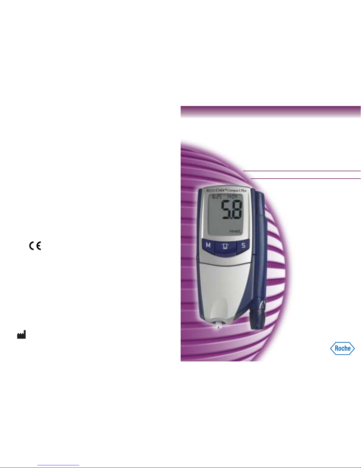
BLOOD GLUCOSE MONITORING SYSTEM
User’s Manual
for
Acoustic Mode
AA
CCU-
CCU-
CHEK
HEK
®
Compact Plus
008
8
ACCU-CHEK and SOFTCLIX
are trademarks of Roche.
Made in Ireland for export to:
Roche Diagnostics
201 Boul. Armand-Frappier
Laval, Québec
CANADA, H7V 4A2
Accu-Chek Customer Care:
Montreal area: (450) 686-7100
Outside Montreal (toll free): 1-800-363-7949
www.accu-chek.ca
Roche Diagnostics GmbH
D-68298 Mannheim, Germany
www.accu-chek.com
Page 2
1
IVD
008
8
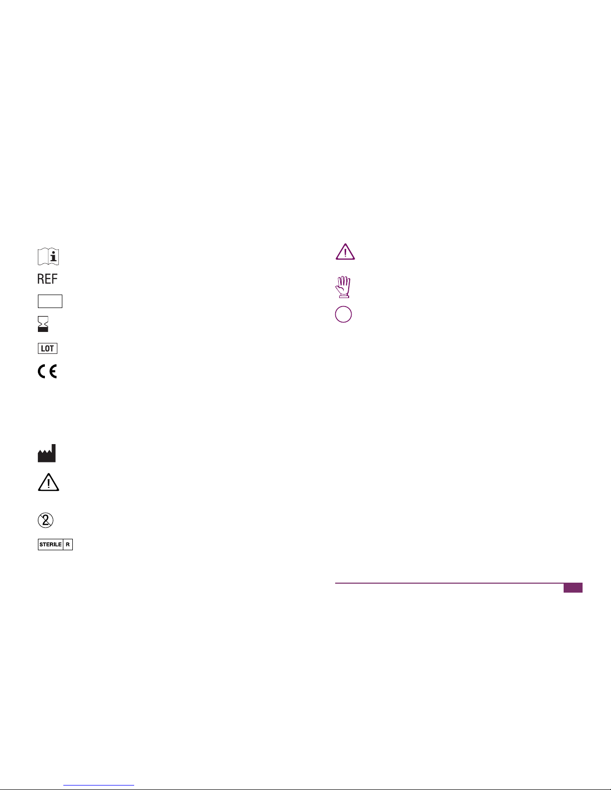
On the packaging, on the type plate of the meter and on the lancing
device you may encounter the following symbols shown here with
their meaning:
Please consult User’s Manual
Catalogue number
For in vitro diagnostic use
Use by/ Expiry date
Lot number
Blood glucose meter and test strips: These products
fulfil the requirements of Directive 98/79/EC on in vitro
diagnostic medical devices.
Lancing device and lancets: These products fulfil
the requirements of Directive 93/42/EEC on medical
devices.
Manufacturer
Caution (refer to accompanying documents). Please
refer to safety-related notes in the User’s Manual
accompanying this instrument.
For single use only
Sterilized using irradiation
Last update: March 2005
This user’s manual for the acoustic mode features three symbols that
draw your attention to important information.
This symbol indicates a possible risk of injury or of damage to
your health.
This symbol draws attention to actions that could result in
damage to meter or lancing device.
i
This symbol draws your attention to other important information.
Page 3
2
3
The acoustic mode is intended for people who are visually impaired.
When the acoustic mode is turned on, the meter will guide the user
through the testing process using beep tones; it will also announce the
results as a series of beeps.
Visually impaired people need a sighted person to instruct them
in the use of the meter and to assist them with all aspects of its
operation. Visually impaired persons must not test their blood
glucose without the assistance of a sighted person.
A person without visual impairment must set up the meter. All the
necessary information for this is contained in the User’s Manual for the
meter.
This user’s manual for the acoustic mode is intended for sighted persons instructing visually impaired people on how to use the Accu-Chek
Compact Plus meter and supporting them in its use.
The user’s manual for the acoustic mode contains separate descriptions
of how to use the meter and the lancing device. These are provided to
support a sighted person, who is instructing a visually impaired person
on how to use the meter and supporting them in its use. Only those
activities, which are to be performed by a visually impaired person
with simultaneous support from a sighted person, are described in this
manual. These activities are:
Inserting and replacing the batteries
Inserting and replacing the test strip drum
Obtaining a blood
Testing blood glucose
Retrieving the results of the best
Descriptions are also given of different acoustic signals which indicate
warnings and error messages.
The user’s manual for the meter covers all the steps involved in
operating the meter as well as warnings and other information.
The user‘s manual for the acoustic mode in spoken form is also available in a CD format. You can receive this CD by calling the Accu-Chek
customer care line. Details are given at the end of this user’s manual.
The user’s manual for the acoustic mode was created in collaboration
with the Centre for Blind and Visually Impaired Students at Fachhochschule Gießen-Friedberg, Germany.
Page 4

4
5
Contents
The user’s manual for the acoustic mode does not replace the
user’s manual for the Accu-Chek Compact Plus meter. Please
study the user‘s manual carefully and completely before using
the meter in acoustic mode. It will provide you with all the information you need to operate and care for the meter and to deal
with any errors that might arise.
If you have any questions, please contact the Accu-Chek customer care
line. Contact details are given at the end of this user’s manual.
Contents
1 Description of the meter ............................................................ 6
1.1 The front ............................................................................. 6
1.2 The back ............................................................................. 7
1.3 The lancing device .............................................................. 8
2 Turning on the acoustic mode ................................................. 10
3 Inserting or replacing batteries ............................................... 11
4 Inserting or replacing the test strip drum ............................... 14
5 Preparing the lancing device ................................................... 16
6 Testing your blood glucose ...................................................... 19
7 Announcement of the results as beeps .................................. 22
8 Ejecting the test strip ............................................................... 24
9 Ejecting the lancet ................................................................... 25
10 Retrieving the results from memory ....................................... 26
11 Warnings and error messages ................................................ 28
12 Local customer support and service ....................................... 30
12.1 Information and repair ....................................................... 30
12.2 Contact us ........................................................................ 31
Page 5

6
Description of the meter
7
Description of the meter
1
1 Description of the meter
The meter is supplied with a lancing device docked onto it.
1.1 The front
Display and buttons
Hold the meter so that the lancing device is located to the right. The two
short ends of the meter have different contours. The smooth end (without projections or depressions) should be pointing away from you. The
other end has a depression and a corner which is rounded off. This end
should be pointing towards you, so the rounded end and lancing device
are on the right. The display and buttons are on the top half of the meter.
In the centre of the meter is the Test button. This can be identified
through its curved ridge. To the left of the Test button is the M button
and to the right of the Test button is the S button. Above the buttons is
the display.
Drum compartment cover
Below the buttons is the drum compartment cover and, underneath it,
the drum compartment. The hinge attaching the drum compartment
cover to the meter is located below the buttons. At the lower end of the
drum compartment cover is a flat depression which continues around
onto the end of the meter nearest to you.
Test strip guide
Below the depression in the drum compartment cover, i.e. at the short
end of the meter nearest to you, is the test strip guide. This is where the
test strip will emerge.
Drum compartment
To the right of the test strip guide is a small projection that is part of the
drum compartment cover. By pulling this projection upwards, you can
open the drum compartment. When the drum compartment is open, a
button (the red drum release button) is situated at its lower right-hand
corner.
1.2 The back
Turn the meter over and lay it down face downwards so the lancing
device is now situated on the left.
Sliding button for undocking the lancing device
At the top left is an oval, ribbed button that slides towards you. This is
the sliding button that releases the lancing device.
Battery compartment
To the right of the sliding button is the battery compartment that
occupies approximately the upper half of the meter. Roughly at the
centre of the meter (i.e. at the lower end of the battery compartment
cover) is a ribbed surface. You push this forward to open the battery
compartment.
Page 6

8
Description of the meter
9
Description of the meter
1
1.3 The lancing device
When the buttons are facing upwards, the lancing device is located on
the right side of the meter. It is docked in a recess in the meter. The
shape of the lancing device is that of a fat ballpoint pen. At its lower
end, adjacent to the end of the meter with the test strip guide, is the
cap. Underneathe the cap is the lancet holder. The cap rotates and is
used to set the penetration depth. Just above the cap, inset into the
lancing device, is a semi-circular arch that has a light-coloured border.
This indicates the chosen penetration depth. The cap is removed to allow a new lancet to be inserted or to eject a used one. At the upper end
of the lancing device is the plunger, which is used to prime, trigger and
eject the lancet.
Undocking and docking the lancing device
씰 Hold the meter so the back is facing upwards, with the lancing
device on the left.
씰 Search for the ribbed sliding button at the top left corner of the
meter.
씰 Slide this button downwards and hold it there.
This releases the lancing device.
씰 Withdraw the lancing device by pulling it forward towards you.
The lancing device is not round like a ballpoint pen, but has four sides
that are different, and have rounded edges. On the two narrow sides of
the lancing device are two narrow grooves that start below the plunger
and run along the lancing device. Along the edges of the recess in the
meter into which the lancing device is docked are the corresponding
guides. These guides must engage with the grooves when the lancing
device is docked onto the meter.
Of the two broad sides one is flat and the other curved. When the
lancing device is docked onto the meter, the curved side faces
outwards.
씰 Slide the lancing device from below, plunger first, into the recess.
The flat, broad side of the lancing device must be facing the meter
and be in contact with the walls of the recess. The guides then glide
into the grooves. The lancing device docks into place with an audible CLICK.
Page 7

10
Turning on Acoustic Mode
2
11
Inserting or replacing batteries
3
2 Turning on Acoustic Mode
씰 With the meter turned off, press the right-hand S button
(S button).
The meter turns on without advancing a test strip.
씰 Press the left-hand M button (M button) repeatedly until it beeps
and On2 flashes in the display. The acoustic mode is now turned on.
씰 Press the middle button
(Test button) to turn the meter off.
i
You cannot set a hypo warning if you have the acoustic mode
turned on (On2). This is to prevent it from being confused with
other beep tones. If you have already set a threshold, the hypo
warning is automatically turned off when you subsequently turn
acoustic mode on.
3 Inserting or replacing batteries
When the batteries are low, the meter emits three double beeps (2 short
beeps three times in quick succession) when you turn it on.
You can now perform about 50 more tests. Continue testing until all the
test strips in your current test strip drum have been used up. Then replace the batteries and the test strip drum.
씰 If the meter is on, press the middle button
(Test button) to turn
it off.
씰 Hold the meter so the back is facing upwards, with the lancing
device on the left.
The battery compartment is located at the top right and extends to
approximately the middle of the meter. At the lower end of the battery
compartment cover is a ribbed area.
씰 Push the ribbed area forward as far as it will go (about 3 mm).
씰 This unlocks the battery compartment and you can remove the
cover.
You may turn the meter over if you wish, so the battery compartment cover drops off. Turn the meter over again so the battery
compartment is again at the top right.
씰 Remove the used batteries.
Page 8

12
Inserting or replacing batteries
13
Inserting or replacing batteries
3
씰 Insert new batteries.
Ensure that the flat, smooth end of the right-hand battery (minus
end) is pointing downwards and the end with the rounded projection
(plus end) is pointing upwards. The left-hand battery must be inserted the other way round, with the smooth, flat end pointing upwards
and the end with the rounded projection pointing downwards.
씰 Place the battery compartment cover loosely back on the battery
compartment.
The battery compartment cover has slots along three edges of the
battery compartment. The three prongs projecting from the cover
must engage in the slots. The battery compartment cover is properly
located over the battery compartment when the cover is loosely
attached and is lying flush with the back of the meter.
씰 Slide the battery compartment cover downwards towards you. It
locks with an audible CLICK.
i
When you replace the batteries, the year, time and date settings
only remain saved as long as
you do not take longer than two minutes to change the
batteries,
you do not press any button while there are no batteries in
the meter and
you do not open the drum compartment while there are no
batteries inserted.
After replacing the batteries, therefore, ask a sighted person to check
and, if necessary, adjust the settings.
If the year, time and date are not correctly entered, your future results
will be displayed and saved without the time and date, in which case
they will be sequentially numbered instead. Statistical calculations (e.g.
of average values) and downloading of results to a computer can only
be performed for results that have been saved together with the year,
time and date.
Page 9

14
Inserting or replacing the test strip drum
15
Inserting or replacing the test strip drum
4
4 Inserting or replacing the test strip drum
The test strip drum is a short cylinder that resembles a full spool of
thread. One end of the test strip drum has a hole in the middle, the other
end has a central, ring-shaped ridge. With the exception of the hole and
the ridge, both ends of the drum are sealed with aluminium foil. On a
new test strip drum this foil must be smooth, a sign that it is undamaged.
씰 Hold the meter so the buttons and the display screen are facing up-
wards with the test strip guide pointing towards you.
To the right of the test strip guide is a small projection that is part of the
drum compartment cover.
씰 Lift the projection upwards to open the drum compartment cover.
씰 Fold the drum compartment cover up as far as it will go.
The drum compartment is a rectangular chamber. At the lower, righthand corner of this chamber is a red button, the drum release button.
씰 Press the red button.
If there is a test strip drum in the meter:
씰 Keeping hold of the drum compartment cover turn over the meter so
the drum compartment is pointing downwards.
The test strip drum drops out.
씰 Turn the meter back over so that the buttons are facing up.
씰 Take a new test strip drum from its container.
씰 Place the test strip drum in the drum compartment.
Ensure that the end with the ring-shaped ridge is pointing in the direction of the test strip guide. The lower edge of the test drum compartment has a rectangular groove at its centre into which the ridge
of the drum fits. When inserting the test strip drum, hold it so the
two aluminium ends are vertical and the cylindrical body is parallel
to the sides of the drum compartment.
The test strip drum will only fit into the drum compartment when it
is correctly aligned.
씰 Fold the drum compartment cover down and press it closed.
It locks with an audible CLICK.
The meter will rotate the test strip drum in order to read the barcode.
You will hear the motor running. The meter then turns itself off.
Page 10

16
Preparing the lancing device
17
Preparing the lancing device
5
5 Preparing the lancing device
When the lancing device is docked onto the meter, the cap is at the end
of the meter where the test strip guide is also located. At the upper end
of the lancing device is the plunger which is used to prime, trigger and
eject the lancet.
씰 Pull the cap off downwards and remove it from the lancing device.
Beneath the cap is a narrow cylinder, the lancet holder.
If there is a lancet in the lancing device, only the lancet needle
protrudes from the lancet holder. To avoid injuring yourself, do not
grasp the lancet holder from the front.
If there is a lancet in the lancing device:
씰 Hold the lancing device upright above a waste bin.
씰 Press the plunger in as far as it will go.
The lancet drops out.
If the lancet does not drop out, a sighted person must remove it. For details refer to the User’s Manual for the meter (chapter entitled “Ejecting
the used lancet”).
Make sure the lancet has dropped out. Inadvertently leaving the
lancet in the lancing device may result in personal injury.
The lancet is a small rectangle with a flat and a rounded end. The
rounded end is the protective cap that is attached to the lancet needle.
씰 Slide a new lancet, flat end first, into the lancing device as far as it
will go. When you hold the meter horizontally, a narrow side of the
lancet (no matter which) must be facing upwards.
The lancet will snap into place with an audible CLICK.
씰 Twist off the rounded end to expose the lancet needle.
씰 Press the cap back onto the lancing device.
There is only one position in which the cap can be properly attached
to the lancing device. To find it, lightly hold the cap against the lancing device and rotate it until you notice the cap slide over the lancet
holder. Press the cap on tight. The cap is properly fitted when it
locks into place with an audible CLICK.
Page 11

18
Preparing the lancing device
19
Testing blood glucose
6
The cap rotates and is used to adjust the lancet penetration depth. Between the cap and the lancing device there is a gap. The wider the gap,
the smaller the depth setting.
씰 Rotate the cap until you reach your chosen setting.
The cap clicks at each penetration depth setting.
6 Testing blood glucose
When you turn on the meter to test blood glucose, shield it from
very strong light sources (e.g. direct sunlight, studio lighting, spot
lights, etc.) until the test has finished and the result has been
announced. Very strong light sources may stop the meter from
functioning correctly and cause error messages to be displayed.
씰 Press the middle button
(Test button) to turn the meter on.
The meter beeps when it is turned on. Shortly after that, you will
hear the motor as the meter advances a test strip.
씰 Wait until you hear the next beep tone.
This is the signal for you to apply blood. You have 5 minutes in
which to do so.
i
If you have not applied blood within 5 minutes, the meter turns
itself off. It does not beep to signal this. If this happens hold the
meter so that the test strip is pointing downwards. Press the
middle button
(Test button) to eject the test strip.
씰 Wash your hands with warm water and soap and dry well. This
helps ensure proper hygiene and stimulates blood flow.
Page 12

20
Testing blood glucose
21
Testing blood glucose
6
씰 Press the plunger all the way down.
The plunger returns about a third of the way. The lancing device is
now primed.
씰 Gently press the front end of the lancing device against a fingertip.
You will feel the slightly raised ring at the centre of which is the
pin-hole through which the lancet needle emerges.
씰 Press the plunger in as far is it will go.
This triggers the lancet, which penetrates the skin.
씰 Gently massage the finger towards the fingertip to encourage a drop
of blood to form.
씰 Hold the meter so the test strip is pointing downwards.
씰 Touch the drop of blood, as soon as it has formed, against the front
edge of the test strip where the black notch is located. The strip
draws up blood.
The meter beeps when the test strip has drawn up sufficient blood.
Measurement starts automatically and 000 will appear in the display.
씰 Move your finger away from the test strip.
Measurement takes approximately 5 seconds. As measurement
progresses, the three 0’s disappear in turn from the display.
If the meter does not beep, you have applied too little blood. You may
apply more blood.
씰 After you have applied blood to the test strip, wipe the puncture site
with a clean, dry tissue. We recommend protecting the site to keep it
clean.
When measurement is complete, the meter emits a double beep (two
short beeps in quick succession). The result is then displayed and also
announced as a series of beeps. The meter automatically saves the
result to memory.
Page 13

22
Announcement of results as beeps
23
Announcement of results as beeps
7
7 Announcement of results as beeps
Numbers are announced through a corresponding number of short
beeps, e.g. four short beeps signify the numeral 4.
Zero is represented by a long beep.
Results larger than 33.3 mmol/L are represented as 999, i.e. three
groups of nine short beeps with pauses between the groups.
Results smaller than 0.6 mmol/L are represented as 000, i.e. three long
beeps.
Following two short beeps signifying the end of measurement the meter
announces the result – tens first, then units, then the decimal point as a
very short beep, and finally the tenths. There is a short pause between
each group.
The result 13.8 mmol/L is announced as follows:
one short beep – pause – three short beeps – pause – one very short
beep – pause – eight short beeps.
The result 4.0 mmol/L is announced as follows:
one long beep (for 0 tens) – pause – four short beeps – pause – one
very short beep – pause – one long beep.
The results are repeated twice. A double beep precedes each repetition.
Page 14

24
Ejecting the test strip
8
25
Ejecting the lancet
9
8 Ejecting the test strip
씰 Hold the meter over a waste bin with the test strip pointing
downwards.
씰 Press the middle button
(Test button) to turn the meter off.
The used test strip drops out.
9 Ejecting the lancet
씰 Pull the cap off downwards and remove it from the lancing device.
씰 Hold the lancing device upright above a waste bin.
씰 Press the plunger in as far as it will go.
The lancet drops out.
If the lancet does not drop out, a sighted person must remove it.
For details refer to the User’s Manual for the meter (chapter entitled
“Ejecting the used lancet”).
Make sure the lancet has dropped out.
Inadvertently leaving the lancet in the lancing device may result
in personal injury.
Page 15

26
Retrieving results from memory
27
Retrieving results from memory
10
10 Retrieving results from memory
In addition to the results and the time and the date, your meter also
saves all additional information that is pertinent to the measurement
(see chapter entitled “Using Accu-Chek Compact Plus as an electronic
notebook” in the User’s Manual for the meter). However, only the most
recently saved result and the average of the last 7 days are announced
acoustically. These two values are represented in the same way as
when the result is announced directly following a test.
씰 With the meter turned off, press the left-hand
M
button (M button).
The most recently saved result is announced. Its announcement is
preceded by a double beep. The announcement is repeated twice,
each time preceded by a double beep.
씰 Press the right-hand
S
button (S button) and the left-hand M
button (M button) at the same time.
The average of the last 7 days is announced. Its announcement is
preceded by a double beep. The announcement is repeated twice,
each time preceded by a double beep.
씰 Press the middle button
(Test button) to turn the meter off.
i
Three long beeps sound if there is no result in memory.
No beep sounds if the average of the last 7 days cannot be
calculated.
i
If the most recently saved result is a quality control result, this is
announced in the same way as any blood glucose result. There
is no acoustic signal to identify quality control results.
Page 16

28
Warnings and error messages
29
Warnings and error messages
11
11 Warnings and error messages
In the case of warnings, flashing symbols appear in the display. In the
acoustic mode, the meter emits three double beeps to indicate a warning. For the complete list please refer to the chapters entitled “Symbols”
and “Messages and troubleshooting” in the User’s Manual for the meter.
Warnings may be issued at various times:
After you turned the meter on:
The batteries are running low: You can now perform about 50 more
tests.
While you are turning the meter off:
You used the last test strip. The test strip drum is empty.
Following a measurement, i.e. following the double beep that
signifies that measurement is complete, and before the result is
announced:
The temperature during measurement was outside the permitted
range of +10 °C to +40 °C.
The 90-day use-by period for the test strip drum has been
exceeded. Insert a new test strip drum.
You inserted a partly used test strip drum. The meter requests
you to perform a quality control check.
While you are retrieving the most recent result from memory,
following the double beep preceding announcement of the result
and before the result is announced:
The temperature during measurement was outside the permitted
range of +10 °C to +40 °C.
The 90-day use-by period for the test strip drum was exceeded.
You had inserted a partly used test strip drum.
After you closed the drum compartment cover:
You inserted a partly used test strip drum or you have opened the
drum compartment and there is a partly used test strip drum in the
meter. The meter requests you to perform a quality control check.
After you closed the battery compartment cover:
You took longer than two minutes to replace the batteries (the year,
date and time settings are lost) and left a partly used drum in the
meter. The meter requests you to perform a quality control check.
The meter displays error messages in the form of an E plus a number.
In the acoustic mode the meter will also emit four double beeps when it
displays an error message. There is no further acoustic differentiation.
For the complete list please refer to the chapter entitled “Messages and
troubleshooting” in the User’s Manual for the meter.
Page 17

30
Local customer support and service
31
Local customer support and service
12
12 Local customer support and service
12.1 Information and repair
Information service
If you have any questions on how to use your Accu-Chek Compact Plus
meter or Accu-Chek Softclix Plus lancing device, if any of the results you
obtain seem implausible, or if you suspect that the meter or lancing device may have a fault, please contact the Accu-Chek customer care line.
See the next chapter for details.
Repair service
Please note that any repair, adjustment or other change to the meter
or lancing device must be performed by a qualified person who has
been authorized by Roche Diagnostics. If you suspect that the meter
or lancing device may have a fault, please start by contacting the
Accu-Chek customer care line. Our staff will attempt to identify and
solve the problem with you over the phone.
12.2 Contact us
If you have any questions or concerns, call the Accu-Chek customer
care line:
Montreal area: (450) 686-7100
Outside Montreal (toll free): 1-800-363-7949
Made in Ireland for export to:
Roche Diagnostics
201 Boul. Armand-Frappier
Laval, Québec
CANADA, H7V 4A2
www.accu-chek.ca
Page 18

32
 Loading...