


p e r a t i n g
M
a n u a l
Operating Manual for
Model 34788-H
Recovery, Recycling, Recharging Unit

Model 34788-H
Recovery, Recycling, & Recharging Unit
SAFETY DEFINITIONS: Follow all WARNING, CAUTION, and NOTE messages in this manual. These messages are defined as follows: WARNING means you may risk serious personal injury or death; CAUTION means you may risk personal injury, property damage, or unit damage; and NOTEs and OPERATING TIPS provide clarity and helpful information. These safety messages cover situations ROBINAIR is aware of. ROBINAIR cannot know, evaluate, and advise you as to all possible hazards. You must verify that conditions and procedures do not jeopardize your personal safety.
DISCLAIMER: Information, illustrations, and specifications contained in this manual are based on the latest information available at the time of publication. The right is reserved to make changes at any time without obligation to notify any person or organization of such revisions or changes. Further, ROBINAIR shall not be liable for errors contained herein or for incidental or consequential damages (including lost profits) in connection with the furnishing, performance, or use of this material. If necessary, obtain additional health and safety information from the appropriate government agencies and the vehicle, refrigerant, and lubricant manufacturers.
 WARNINGS
ALLOW ONLY QUALIFIED PERSONNEL TO OPERATE THE UNIT. Before operating the unit, read and follow
the instructions and warnings in this manual. The operator must be familiar with air conditioning and refrigeration
systems, refrigerants, and the dangers of pressurized components. If the operator cannot read this manual, operating instructions and safety precautions must be read and discussed in the operator’s native language.
PRESSURIZED TANK CONTAINS LIQUID REFRIGERANT. Do not overfill the internal storage vessel, because overfilling may cause explosion and personal injury or death. Do not recover refrigerants into nonrefillable containers; use only federally authorized refillable containers (DOT spec. 4BW or 4BA).
HOSES MAY CONTAIN LIQUID REFRIGERANT UNDER PRESSURE. Contact with refrigerant may cause personal injury. Wear protective equipment, including safety goggles. Disconnect hoses using extreme caution.
AVOID BREATHING A/C REFRIGERANT AND LUBRICANT VAPOR OR MIST. Exposure may irritate eyes, nose, and throat. To remove refrigerant from the A/C system, use only equipment certified for the type of refrigerant being removed.
DO NOT USE AN EXTENSION CORD. An extension cord may overheat and cause fire. If you must use an extension cord, use the shortest possible cord with a minimum size of 14 AWG.
TO REDUCE THE RISK OF FIRE, do not use the unit in the vicinity of spilled or open containers of gasoline
or other flammable substances.
CAUTION—DO NOT PRESSURE TEST OR LEAK TEST EQUIPMENT AND / OR VEHICLE AIR CONDI-
TIONING SYSTEMS WITH COMPRESSED AIR. Some mixtures of air and refrigerant have been shown to be


 combustible at elevated pressures. These mixtures, if ignited, may cause injury or property damage.
TO PREVENT CROSS-CONTAMINATION, USE THIS UNIT WITH R-134A REFRIGERANT ONLY. The unit is designed to recover, recycle, and recharge only R-134a refrigerant. Do not attempt to adapt the unit for another refrigerant. Do not mix refrigerant types through a system or in the same container; mixing of refrigerants will cause severe damage to the unit and the vehicle air conditioning system.
HIGH VOLTAGE ELECTRICITY INSIDE THE UNIT HAS A RISK OF ELECTRICAL SHOCK. Exposure may cause personal injury. Disconnect the power before servicing the unit.
Additional health and safety information may be obtained from the refrigerant and lubricant manufacturers.
OPERATING NOTE: At temperatures exceeding 120° F / 49° C, wait 10 minutes between recovery jobs.

Table of Contents
Introduction . . . . . . . . . . . . . . . . . . . . . . . . . . . . . . . . . |
. . . . . . . . . . . . |
. |
. . |
. |
2 |
Technical Specifications . . . . . . . . . . . . . . . . . . . . . . |
. . . . . . . . . . . . |
. |
. . |
. |
2 |
Keypad Functions . . . . . . . . . . . . . . . . . . . . |
. . . . . . . . . . |
. |
. |
. |
3. . . . . . . . . |
Glossary . . . . . . . . . . . . . . . . . . . . . . . . . . . . . . . . . . |
. . . . . . . . . . . . |
. |
. . |
. |
3 |
Menu Functions . . . . . . . . . . . . . . . . . . . . . . . . . . . . |
. . . . . . . . . . . . |
. . |
. |
. |
4 |
Setup . . . . . . . . . . . . . . . . . . . . . . . . . . . . . . . . . . . . . . |
. . . . . . . . . . . . |
. . |
. |
. |
5 |
Unpack the Accessory Kit . . . . . . . . . . . . . . . |
. . . . . . . . . . |
. |
. |
. |
5. . . . . . . . |
Power Up the Unit . . . . . . . . . . . . . . . . . . . . . . . . |
. . . . . . . . . . . |
. . . |
. |
5. . . |
|
Select a Language . . . . . . . . . . . . . . . . . . . . . . . . . . |
. . . . . . . . . . . . |
. . |
. |
. |
5 |
Select Operating Units . . . . . . . . . . . . . . . . . . . . . . . |
. . . . . . . . . . . . |
. . |
. |
. |
5 |
Set Tank Fill Level . . . . . . . . . . . . . . . . . . . . . . . |
. . . . . . . . . . . |
. |
. . |
. |
6. . . . |
Add Oil to the Vacuum Pump . . . . . . . . . . . . . . . . . . |
. . . . . . . . . . . . |
. . |
. |
. |
6 |
Fill the Internal Storage Vessel . . . . . . . . . . . . |
. . . . . . . . . . |
. |
. |
. |
7. . . . . . . |
Operating Instructions . . . . . . . . . . . . . . . . . . . . |
. . . . . . . . . . |
. |
. |
. .8. . . . . . |
|
Recover Refrigerant from a Vehicle . . . . . . . . . . . . . |
. . . . . . . . . . . . |
. . |
. |
. |
8 |
Evacuate the A/C System . . . . . . . . . . . . . . . |
. . . . . . . . . . |
. |
. |
. |
9. . . . . . . . |
Replenish A/C System Oil . . . . . . . . . . . . . . . . . . |
. . . . . . . . . . . . . |
. .10. . |
|||
Recharge the A/C System . . . . . . . . . . . . . . . . . . . . |
. . . . . . . . . . . . |
. . |
. |
11 |
|
Operating Instructions — Automatic . . . . . . . . . . . . . |
. . . . . . . . . . . . |
. . |
. |
13 |
|
System Flush . . . . . . . . . . . . . . . . . . . . . . . . . . . . . . . . |
. . . . . . . . . . . . |
. . |
. |
15 |
|
Maintenance . . . . . . . . . . . . . . . . . . . . . . . . . . . . . . . . . |
. . . . . . . . . . . . |
. . |
. |
18 |
|
General . . . . . . . . . . . . . . . . . . . . . . . . . . |
. . . . . . . . . . |
. . |
17. . . . . . . . . . . |
||
Electrical Protection . . . . . . . . . . . . . . . . . . . . . . . . . |
. . . . . . . . . . . . |
. . |
. |
17 |
|
Manually Fill the Internal Storage Vessel (ISV) . . . . |
. . . . . . . . . . . . |
. . |
. |
17 |
|
Tank Fill Hose Filter Service . . . . . . . . . . . . . |
. . . . . . . . . . . 18. . . . . . . . . |
||||
Replace the Filter-Drier . . . . . . . . . . . . . . . . . . . . . . . . . . . . . . . . . . .19. . |
|||||
Adjust Tank Fill Level . . . . . . . . . . . . . . . . . . . . . . . . |
. . . . . . . . . . . . |
. . |
. |
20 |
|
Change Vacuum Pump Oil. . . . . . . . . . . . . . . . . . . . |
. . . . . . . . . . . . |
. . |
. |
21 |
|
Scale Calibration Check . . . . . . . . . . . . . . |
. . . . . . . . |
. |
. |
.22. . . . . . . . . . . |
|
Check for Leaks . . . . . . . . . . . . . . . . . . . . . . . . . . . . |
. . . . . . . . . . . . |
. . |
. |
22 |
|
Replacement Parts . . . . . . . . . . . . . . . . . . |
. . . . . . . . . |
. |
. 23. . . . . . . . . . . |
||
Spanish Manual . . . . . . . . . . . . . . . . . . . . . . . . . . . . . . |
. . . . . . . . . . . . |
. . |
. |
25 |
|
French Manual . . . . . . . . . . . . . . . . . . . . . . . . . . . . . . . |
. . . . . . . . . . . . |
. . |
. |
49 |
|
Safety Precautions . . . . . . . . . . . . . . . . . . . . . |
. Inside. . . . Front. . |
Cover |
|||
Warranty . . . . . . . . . . . . . . . . . . . . . . . . . . . . . . . . . . . . |
. .Inside Back Cover |
||||
IMPORTANT: To comply with federal law governing A/C system service, you must complete and mail the MVAC Certification Form included in the accessory kit. Technicians using this equipment must be certified under EPA Section 609 (Environmental Protection Agency). For more information, read the MACS information included in the accessory kit, or visit the MACS website at www..macsw..org..
To validate the warranty provided by Robinair, complete the warranty card included in the accessory kit, and mail it within ten days from the purchase date of the unit..
560826 Rev. D, August 23, 2013 |
1 |

Introduction
Robinair No. 34788-H is used on R-134a vehicles and is designed to be compatible with existing service equipment and standard service procedures. This unit is a UL-listed, singlepass system that meets SAE specifications for recycled refrigerant. Follow the SAE-J2211 recommended service procedure for the containment of R-134a.
The unit includes a 1.5 cfm (42 l/m) Robinair high vacuum pump for fast, thorough evacuation. The compressor pulls the A/C system to 0 psig, then works in series with the vacuum pump to achieve highly efficient recovery and immediate recharge. If the system is not opened for service, there is no need to pull additional vacuum. If the system is opened for service, use the unit’s vacuum cycle to remove air and moisture from the A/C system. (We recommend
a minimum 15-minute vacuum, or follow the vehicle manufacturer’s specs.) Note: R-134a systems require special oils. Refer to the A/C system manufacturer’s service manual for oil specifications.
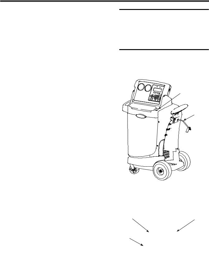
Control Panel: folds flat for storage.
Manifold Gauges: connect to vehicle A/C system; show system’s low-side and high-side pressure.
Tool Storage Areas
(additional storage on back side for extra filter-driers and oil bottles).
Flow Indicators: red  light indicates high-side
flow from vehicle A/C system through unit; blue light indicates lowside flow from vehicle A/C system through unit.
Digital Display: visual interface between operator and machine.
Main Power Switch: supplies electrical power to unit.
Technical Specifications
Voltage . . . . . . . . . . . . . . . . . . . . 115V,. . . 60 Hz
Operating Range . . 50° to 120° F (11° to 49° C) Filter-Drier . . . . . . . . . 43. . cu. . in. spin-on type
Pump Free-Air Displacement . 1. .5 cfm (42 l/m)
Dimensions . . . . . . . . 49". . .H x 34" W x 23" D
. . . . . . . . . . .(124.5 cm x 86.4 cm x 58.4 cm)
2

Introduction
Keypad Functions
START
YES
STOP
NO
MENU
AUTOMATIC
START / YES begins or resumes a function, or answers a query.
STOP / NO terminates or pauses a function, or answers a query.
MENU displays the selection menu.
ARROWS are used for scrolling through menu items.
AUTOMATIC activates a menu that helps the user set up an automatic recover / vacuum / leak test / charge sequence.
RECOVER
VACUUM
INJECT OIL
CHARGE
REFRIGERANT
DATABASE
RECOVER activates the recovery sequence.
VACUUM activates the vacuum sequence, followed by an option to activate a leak test.
INJECT OIL – not applicable to this unit.
CHARGE charges the vehicle A/C system with a programmed amount of refrigerant.
REFRIGERANT DATABASE (optional) offers access to system oil and refrigerant specifications by vehicle model and year. Purchase Robinair No. 34411.
When the unit is not performing a function, pressing the UP or DOWN arrow key adjusts contrast on the digital display.
Keypad
Glossary
A/C System : The vehicle air conditioning system being serviced.
Internal Storage Vessel : The refillable refrigerant storage vessel designed specifically for this unit; 30 lb. (14 kg).
Source Tank : A disposable tank of new refrigerant used to refill the internal storage vessel; not included.
Unit : Model No. 34788-H.
560826 Rev. D, August 23, 2013 |
3 |

Introduction
Menu Functions
1.Press the MENU button on the keypad.
2.Press the UP or DOWN arrow key to scroll through the menu choices shown on the second line of the display :
SELECT LANGUAGE VERSION X.XX SELECT UNITS MAINTAIN VACUUM OIL MAINTAIN FILTER REFRIG MANAGEMENT MANUAL REFILL ADJUST TANK FILL LVL CALIBRATION CHECK SELECT BEEPER TONE SERVICE MENU
HOSE FLUSH DISPLAY TANK INFO SYSTEM FLUSH
3.Press START / YES to make a choice from the menu. Press STOP / NO to pause during any process, and STOP / NO a second time to exit a process.
Start / Yes |
Stop / No |
Button |
Button |
Arrow
Keys
Menu
Button
Select Language
Operatormaychoosetohavepromptsdisplayedinoneofthree languages: English, Spanish, or French.
Version X..XX
Displays the revision level of the software in the unit.
Select Units
The operator may choose to have test results displayed in
Imperial (lb.), Imperial (lb. and oz.), or Metric (kg).
Maintain Vacuum Oil
For maximum vacuum pump performance, change vacuum pump oil after every 10 hours of operation. This menu item
displays how long the vacuum pump has operated since the last oil change, and allows the user to reset the value once an oil change is complete. Refer to the instructions outlined in the Maintenance section under Change Vacuum Pump Oil..
Maintain Filter
The filter-drier removes acid, particulates, and moisture from the refrigerant. To meet SAE J-2788 requirements, it is mandatory to replace the filter-drier after 150 lbs. (68 kg) of refrigerant has been filtered. This menu item shows how much refrigerant has been filtered since the last filter change, and allows the user to reset the value once a filter change is complete. A code, which appears on the filter, must beenteredintotheunittoensurecompliancewithSAEJ-2788. Refer to instructions outlined in the Maintenance section under
Replace the Filter-Drier..
Refrig Management
Displays the amount of refrigerant recovered, charged, and replenished (for the life of the unit), and filtered (since the last filter change).
Manual Refill
Use to transfer refrigerant from the source tank to the internal storage vessel (ISV). Refer to instructions outlined in the Maintenance section under Manually Fill the ISV..
Adjust Tank Fill LVL
When connected to a refrigerant source, the unit maintains a pre-set amount of refrigerant in the internal storage vessel (default is 15 lbs.). This value may be adjusted up or down to suit the user’s needs. Refer to instructions outlined in the Maintenance section under Adjust Tank Fill Level..
Calibration Check
Use to verify internal scale calibration. Refer to instructions in Maintenance section under Scale Calibration Check..
Select Beeper Tone
Select one of two tones for an alert signal, or mute the signal completely.
Service Menu
For Robinair service center use only.
Hose Flush
Flushes residual PAG oil from the unit for service of electric POE oil-based hybrid systems.
Display Tank Info
Displaysinternalstoragevessel(ISV)pressureandtemperature. Use to check the ISV for excessive pressure.
System Flush
When used with the appropriate flush adapter kit, this menu item allows the A/C system or component to be flushed with
R-134a refrigerant.
4
Setup
Unpack the Accessory Kit
Unpack the accessory kit from the bag, and remove the plastic packaging. The kit consists of
•A calibration weight.
•Vacuum pump oil, oil filler cap, and tube.
•Plastic pouch containing a warranty card (to be completed and mailed), applicable MSDS
sheets, a service center listing, and an envelope of Mobile Air Conditioning Society (MACS) information.
Important: You must complete and mail the MVAC Certification Form and your technicians must be certified with the Environmental Protection Agency (EPA)to operate this equipment.
Power Up the Unit
1.Unwind the power cord from the handle, and plug it into a correct voltage outlet. See Figure
1..
2.Turn on the main power switch. The first time the unit is powered up, it displays the initial setup mode.
Select a Language – English Seleccionar Idioma – Espanol Selection Langue – Francais
The operator may choose to have prompts displayed in one of three languages: English, Spanish, or French.
1.Use the UP or DOWN arrow key to toggle through the choices of English, Spanish, or French. Refer to Figure 2.
2.Press START / YES to select the displayed language.
Select Operating Units
The operator may choose to have test results displayed in Imperial (lb., or lb. and oz.) or Metric (kg) units.
1.Use the UP or DOWN arrow key to toggle through the choices of IMPERIAL UNITS or METRIC UNITS.
2.Press START / YES to select the displayed operating unit choice.
CAUTION: R-134a systems have special fittings (per SAE specifications) to avoid cross-contamination with R-12 systems.. DO NOT adapt your unit for a different refrigerant — system failure will result..
Main
Power Switch
Power
Cord
Figure 1
Start / Yes |
Stop / No |
Button |
Button |
Arrow
Keys
Figure 2
560826 Rev. D, August 23, 2013 |
5 |
Setup
Set Tank Fill Level
The operator may either accept the unit’s pre-set default weight of 15 lbs. (6.8 kg) of refrigerant stored in the internal storage vessel (ISV),
or change the amount to accommodate the application.
The unit displays
LEVEL: 15.00 LBS.
ENTER TANK FILL LVL
LIMIT: 4 TO 17 LBS.
PRESS START / YES TO SAVE
1.Press START / YES to accept the default amount, or use the keypad to enter a desired amount and press START / YES.
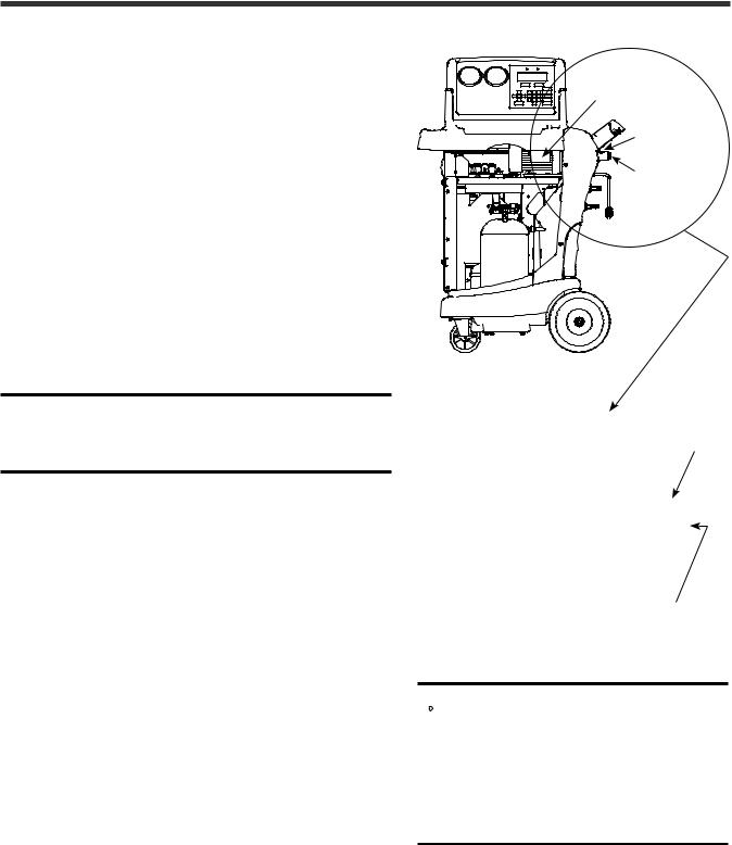
Add Oil to the Vacuum Pump
CAUTION: The vacuum pump is shipped without oil in the reservoir.. Failure to add oil to the vacuum pump will damage the pump..
The unit displays
ADD 5 OZ OF NEW OIL
TO VACUUM PUMP
START TO CONTINUE
1.Remove the brass plug from the vacuum pump oil fill port. See Figure 3.
2.Attach the flexible tube/cap to the oil bottle; pour only five (5) ounces of vacuum pump oil into the fill port. Note: You will top off the oil in the next step as the vacuum pump is running.
3.Press and release the START / YES key. While the vacuum pump is running, slowly add oil until the level rises to the center of the reservoir’s sight glass.
4.Press the STOP / NO key to stop the vacuum pump, and install the brass plug in the fill port.
5.Press START / YES to continue.
Vacuum Pump
Fill Port
Sight
Glass
Fill Port
Figure 3
Sight Glass
 CAUTION: The unit is programmed to run the setup procedure as outlined here.. To prevent personal injury, do NOT operate the unit at any other
time without the brass plug installed, because the vacuum pump is pressurized during normal operation..
6

Setup
Fill the Internal Storage Vessel (ISV)
1. Press START / YES, and the unit automatically runs a 5-minute vacuum to clear all internal air.
Note: The “burping” noise heard during this process indicates air is being purged from the system—this is normal.
2.After the vacuum pump shuts off, connect the fill hose to the liquid connector on a full source tank.
3. Open the source tank valve.
4.Install the source tank, and secure it to the unit (using the tank strap) in such a way that liquid refrigerant is supplied to the connection.
5.Press START / YES to begin filling the internal storage vessel. Add at least 8 lbs. (3.6 kg) of refrigerant to ensure enough refrigerant is available for charging.
This process takes 15–20 minutes. The unit stops when a sufficient amount of refrigerant has been transferred to the internal tank, or when the source tank is empty.
Press STOP / NO to pause. Press STOP |
|
/ NO again to exit, or START / YES to |
Figure 4 |
resume. |
Side View |
6. When the fill process is complete, press |
|
STOP / NO to exit. The unit is ready for |
|
operation. |
|
Note: There is no need to calibrate the scale; it is calibrated at the factory.
Lowand
High-Side
Hoses
Power
Cord
Fill Hose
(connect to liquid line)
Source
Tank
Strap
560826 Rev. D, August 23, 2013 |
7 |
 Loading...