


O |
|
p |
|
e |
|
r |
|
a |
Operating Manual |
t |
Manual de funcionamiento |
i |
Manuel d’utilisation |
n g
M
a n u a l
Not for use in automotive
R-134a applications.
Model 25200B
Refrigerant Recovery Unit
Model 25200B
Refrigerant Recovery Unit
Design Pressure: 336 psig — 435 psig
SAFETY DEFINITIONS: Follow all WARNING, CAUTION, IMPORTANT, and NOTE messages in this manual. These messages are defined as follows: WARNING means you may risk serious personal injury or death; CAUTION means you may risk personal injury, property damage, or unit damage; IMPORTANT means you may risk unit damage; and NOTEs and operating Tips provide clarity and helpful information. These safety messages cover situations ROBINAIR is aware of. ROBINAIR cannot know, evaluate, and advise you as to all possible hazards. You must verify that conditions and procedures do not jeopardize your personal safety.
DISCLAIMER: Information, illustrations, and specifications contained in this manual are based on the latest information available at the time of publication. The right is reserved to make changes at any time without obligation to notify any person or organization of such revisions or changes. Further, ROBINAIR shall not be liable for errors contained herein or for incidental or consequential damages (including lost profits) in connection with the furnishing, performance, or use of this material. If necessary, obtain additional health and safety information from the appropriate government agencies and the vehicle, refrigerant, and lubricant manufacturers.
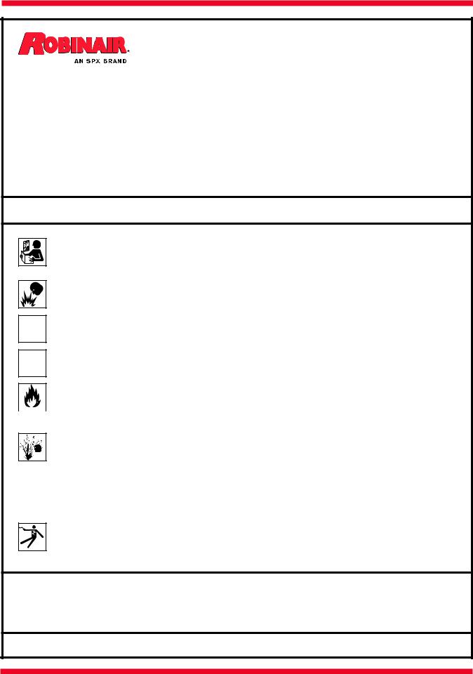
 WARNINGS
ALLOW ONLY QUALIFIED PERSONNEL TO OPERATE THE UNIT. Before operating the unit, read and follow
the instructions and warnings in this manual. The operator must be familiar with air conditioning and refrigeration
systems, refrigerants, and the dangers of pressurized components. If the operator cannot read this manual, operating instructions and safety precautions must be read and discussed in the operator’s native language.
PRESSURIZED TANK CONTAINS LIQUID REFRIGERANT. Donotoverfilltheinternalstoragevessel,because overfilling may cause explosion and personal injury or death. Do not recover refrigerants into nonrefillable containers; use only federally authorized refillable containers (DOT spec. 4BW or 4BA).
HOSES MAY CONTAIN LIQUID REFRIGERANT UNDER PRESSURE. Contact with refrigerant may cause personal injury. Wear protective equipment, including safety goggles. Disconnect hoses using extreme caution.
DO NOT BREATHE REFRIGERANT AND LUBRICANT VAPOR OR MIST. Exposure may cause personal injury, especially to the eyes, nose, throat, and lungs. Use the unit in locations with mechanical ventilation that provides at least four air changes per hour, or position the unit 18 inches above the floor. If accidental system discharge occurs, ventilate the work area before resuming service.
DO NOT USE AN EXTENSION CORD. An extension cord may overheat and cause fire. If you must use an  extension cord, use the shortest possible cord with a minimum size of 14 AWG.
 TO REDUCE THE RISK OF FIRE, do not use the unit in the vicinity of spilled or open containers of gasoline or other flammable substances.
DO NOT USE COMPRESSED AIR TO PRESSURE TEST OR LEAK TEST THE UNIT OR HVAC/R SYSTEM.
Some mixtures of air and refrigerant are combustible at elevated pressures. These mixtures are potentially


 dangerous and may result in fire or explosion causing personal injury or property damage.
USE THIS UNIT WITH only the following REFRIGERANTs: R-12, R-22, R-134a, R-401a, R-401B, R-402A, R-402B, R-404A, R-407A, R-407B, R-407C, R-408A, R-409A, R-410A, R-500, R-502, R-507. The unit is designed to only recover refrigerant. Do not attempt to adapt the unit for refrigerant that is not in this list. Do not mix refrigerant types through a system or in the same container; mixing of refrigerants will cause severe damage to the unit and the air conditioning system.
HIGH VOLTAGE ELECTRICITY INSIDE THE UNIT HAS A RISK OF ELECTRICAL SHOCK. Exposure may
cause personal injury. Disconnect the power before servicing the unit.
additional health and safety information may be obtained from the refrigerant and lubricant manufacturers.
This equipment has been certified by ARI to meet the EPA minimum requirements for recovery equipment intended for use with all HCFC applicances and other high pressure applicances.
Operating Note: At temperatures exceeding 120° F / 49° C, wait 10 minutes between recovery jobs.

Introduction
Table of Contents
Glossary of Terms . . . . . . . . . . . . . . . . . . . . . . . . . . . 1
Operating Guidelines . . . . |
. . . |
. . |
. |
. |
. |
|
2 |
|
Setup Instructions . . . . . |
. . . |
. . |
. |
. |
. |
2 |
||
Operating Instructions . . . |
. . . |
. . |
. |
. |
. |
. |
|
4 |
Recovery Procedure . . . |
. . . |
. . |
. |
. |
. |
. |
|
4 |
Tank-to-Tank Transfer . |
. . . |
. . |
. |
. |
. |
. . . |
|
5 |
High Pressure . . . . . . |
. . . |
. . |
. . |
. |
5 |
|||
Self-Clearing Procedure . . . . . . . . . . . . . . . . . . . . . . 6 |
||||||||
Maintenance . . . . . . . . . . . . . . . . . . . . . . . . . . . . . . 7 |
||||||||
Replacement Parts . . . |
. . . |
. . |
. |
. |
. |
. |
|
7 |
Troubleshooting Tips . . . . |
. . . |
. . |
. |
. |
. |
|
8 |
|
Flow Diagram . . . . . . . . |
. . . |
. . . . |
. |
9 |
||||
Wiring Diagram . . . . . . |
. . . |
. . |
. . . . . . . . . . . . . . . . |
10 |
||||
Conversion Chart . . . . . . |
. . . |
. . |
. . |
11 |
||||
Warranty Statement . . . . |
. . . |
. . |
. |
. |
. |
12 |
||
Safety Precautions . . . . . |
. . . |
. . |
. |
. inside front cover |
||||
Glossary of Terms
A/C-R |
Air conditioning or refrigeration.. |
A/C-R System |
The air conditioning or refrigeration system being serviced.. |
Unit |
The refrigerant recovery unit.. |
Tank |
The refillable refrigerant tank. |
1
552701 Rev. A April 7, 2009

Setup Instructions
Operating Guidelines
•The voltage at the unit must be ±10% of the unit’s rated voltage.
•Extension cords must be a minimum of 14 AWG and kept as short as possible.
•To minimize mixing of refrigerants, the self-clearing procedure must be performed after each recovery operation.
•The low-side gauge on the unit allows you to monitor system pressure and stop recovery when a deep enough vacuum has been reached. The high-side gauge allows you to monitor the refillable tank pressure.
•When changing from liquid to vapor, the unit may switch back and forth several times before staying on vapor. You may notice the liquid light switching and hear the solenoids opening and closing. This is normal and does not affect the unit or its operation.
SET-UP INSTRUCTIONS
The unit comes with four 60-inch Enviro-Guard hoses with ball valves. Either blue hose may be used where blue hose connections are called for, and either red hose may be used for red hose connections.
CAUTION: To prevent personal injury, all valves on hoses must be in the closed position before making connections.
1. |
Connect the hoses as follows: |
|
|
|
|
|
|
|
Hose |
Connect Standard End To: |
Connect Ball Valve End To: |
|
Blue Hose |
TANK LIQUID fitting on unit |
LIQUID port on tank |
|
Red Hose |
TANK VAPOR fitting on unit |
VAPOR port on tank |
|
Blue Hose |
SYSTEM VAPOR fitting on unit |
SYSTEM VAPOR port |
|
Red Hose |
SYSTEM LIQUID fitting on unit |
SYSTEM LIQUID port |
2. |
Plug the unit into a correct voltage electrical outlet. The fan starts running |
||
|
immediately and the unit is ready for operation. |
|
|
2

Setup Instructions
Liquid Indicator
System Pressure |
Tank Pressure |
Circuit Breaker
High Pressure Indicator 
Recover / Power / Clear
Switch
Front View of Unit
Liquid Vapor |
|
Valve Valve |
TyPICAL |
|
|
|
A/C-R SySTEM |
|
Vapor |
|
TANk VAPOR |
|
Liquid |
|
SySTEM VAPOR |
TANk LIQUID |
SySTEM LIQUID |
|
Hose Connections
3
552701 Rev. A April 7, 2009
 Loading...