

Page 1
OPERA TING
○○○○○○○○○○○○○○○○○○○○○○○○○○○○○○○○○○○○○○○○○○○○○○○○○○○○○○○○○○○○○○○○○○○○○○○○○○○○
M
ANUAL
Model 34134Z
Refrigerant Unit
Recover, Recycle, and Recharge
Page 2
Recover, Recycle, and Recharge Unit
Model: 34134Z
LISTED
80S2
Recycling Equipment Design
Certified by Underwriters
Laboratories Inc.® for
Compliance with SAE-J2210
(1991) for HFC-134a
Refrigerant: R-134a
Voltage: 115, 60 Hz
SAFETY DEFINITIONS: Follow all WARNING, CAUTION, IMPORTANT, and NOTE messages in this manual.
These messages are defined as follows: WARNING means you may risk serious personal injury or death;
CAUTION means you may risk personal injury, property damage, or serious unit damage; IMPORTANT means
you may risk unit damage; and NOTEs provide clarity and helpful tips. These safety messages cover situations
ROBINAIR is aware of. ROBINAIR cannot know, evaluate, and advise you as to all possible hazards. You must
make sure all conditions and procedures do not jeopardize your personal safety.
COPYRIGHT: No part of this manual may be reproduced, stored in a retrieval system, or transmitted in any form
or by any means (electronic, mechanical, photocopy, recorded, or otherwise) without the prior written permission of
ROBINAIR.
DISCLAIMER: All information, illustrations, and specifications contained in this manual are based on the latest
information available at the time of publication. The right is reserved to make changes at any time without
obligation to notify any person or organization of such revisions or changes. Further, ROBINAIR shall not be liable
for errors contained herein or for incidental or consequential damages (including lost profits) in connection with the
furnishing, performance, or use of this material. If necessary, obtain additional health and safety information from
the appropriate government agencies and the vehicle, refrigerant, and lubricant manufacturers.
WARNINGS
ALLOW ONLY QUALIFIED PERSONNEL TO OPERATE THE UNIT. Before operating the unit,
read and follow the instructions and warnings in this manual. The operator must be familiar with air
conditioning and refrigeration systems, refrigerants, and the dangers of pressurized components. If
the operator cannot read these instructions, operating instructions and safety precautions must be
read and discussed in the operator’s native language.
– Si el operador no puede leer las instrucciones, las instrucciones de operación y las
precauciones de seguridad deberán leerse y comentarse en el idioma nativo del operador.
– Si l’utilisateur ne peut lire les instructions, les instructions et les consignes de sécurité doivent
lui être expliquées dans sa langue maternelle.
PRESSURIZED TANK CONTAINS LIQUID REFRIGERANT. Do not recover or charge refrigerants
into non-refillable containers; use only authorized refillable containers.
ALL HOSES MAY CONTAIN LIQUID REFRIGERANT UNDER PRESSURE. Contact with
refrigerant may cause personal injury. Wear protective equipment, including safety goggles.
Disconnect hoses with extreme caution.
DO NOT BREATHE REFRIGERANT AND LUBRICANT VAPOR OR MIST. Exposure may cause
personal injury, especially to the eyes, nose, throat, and lungs. Use the unit in locations with
mechanical ventilation that provides at least four air changes per hour. If accidental system
discharge occurs, ventilate the work area before resuming service.
AVOID USING AN EXTENSION CORD. An extension cord may overheat and cause fire. If you
must use an extension cord, use the shortest possible cord with a minimum size of 14 AWG.
TO REDUCE THE RISK OF FIRE, do not use the unit in the vicinity of spilled or open containers
of gasoline or other flammable substances.
DO NOT USE COMPRESSED AIR TO PRESSURE TEST OR LEAK TEST THE UNIT OR
VEHICLE AIR CONDITIONING SYSTEM. Some mixtures of air and refrigerant are combustible at
elevated pressures. These mixtures are potentially dangerous and may result in fire or explosion
causing personal injury or property damage.
USE THIS UNIT WITH ONLY R-134a REFRIGERANT. The unit is for recovering, recycling, and
recharging only R-134a refrigerant! Do not attempt to adapt the unit for another refrigerant. Do not
mix refrigerant types through a system or in the same container; mixing of refrigerants will cause
severe damage to the unit and the vehicle air conditioning system.
HIGH VOLTAGE ELECTRICITY INSIDE THE UNIT HAS A RISK OF ELECTRICAL SHOCK.
Exposure may cause personal injury. Disconnect the power before opening the back door or
servicing the unit.
Page 3

Table of Contents
Safety Precautions....................................................... inside front cover
Introduction ......................................................................................... 2
General Description .........................................................................................2
Glossary of Terms............................................................................................2
Component Identification and Location............................................................3
Unit Front View .........................................................................................3
Unit Side View...........................................................................................3
Unit Back View..........................................................................................4
Vacuum Pump ..........................................................................................4
Control Panel ............................................................................................5
Initial Setup.......................................................................................... 6
Unpacking the Accessory Kit ...........................................................................6
Registering the Unit..........................................................................................6
Adding Vacuum Pump Oil ................................................................................7
Adding Refrigerant to the Internal Storage Vessel...........................................9
Drain Oil ..................................................................................................11
Changing the Temperature Scale ..................................................................12
Operation ............................................................................................13
Operating Guidelines .....................................................................................13
Recovering the A/C System Refrigerant ........................................................15
Draining the A/C System Oil ..........................................................................17
Evacuating the A/C System ...........................................................................18
Replenishing the A/C System Oil ...................................................................19
Purging Air from the Internal Storage Vessel.................................................20
Recharging the A/C System Refrigerant ........................................................21
Maintenance .......................................................................................23
Adding Additional Refrigerant to the Internal Storage Vessel ........................23
Drain Oil ..................................................................................................24
Changing the Vacuum Pump Oil....................................................................25
Resetting Oil Time ..................................................................................26
Replacing the Filter-drier................................................................................27
Resetting the Filter-drier Capacity ..........................................................29
Checking for Leaks ........................................................................................30
Calibrating the Weight Scale..........................................................................31
Cleaning the Unit............................................................................................31
Replacement Parts.............................................................................31
R-134a Temperature / Pressure Table..............................................32
Limited Warranty..........................................................inside back cover
Manufactured under one or more of the following US patents: US 4,938,031; 5,005,369;
5,248,125; 4,261,178; 4,768,347. Other US and foreign patents pending.
Recover/Recycle/Recharge Unit
1
Page 4
Introduction
General Description
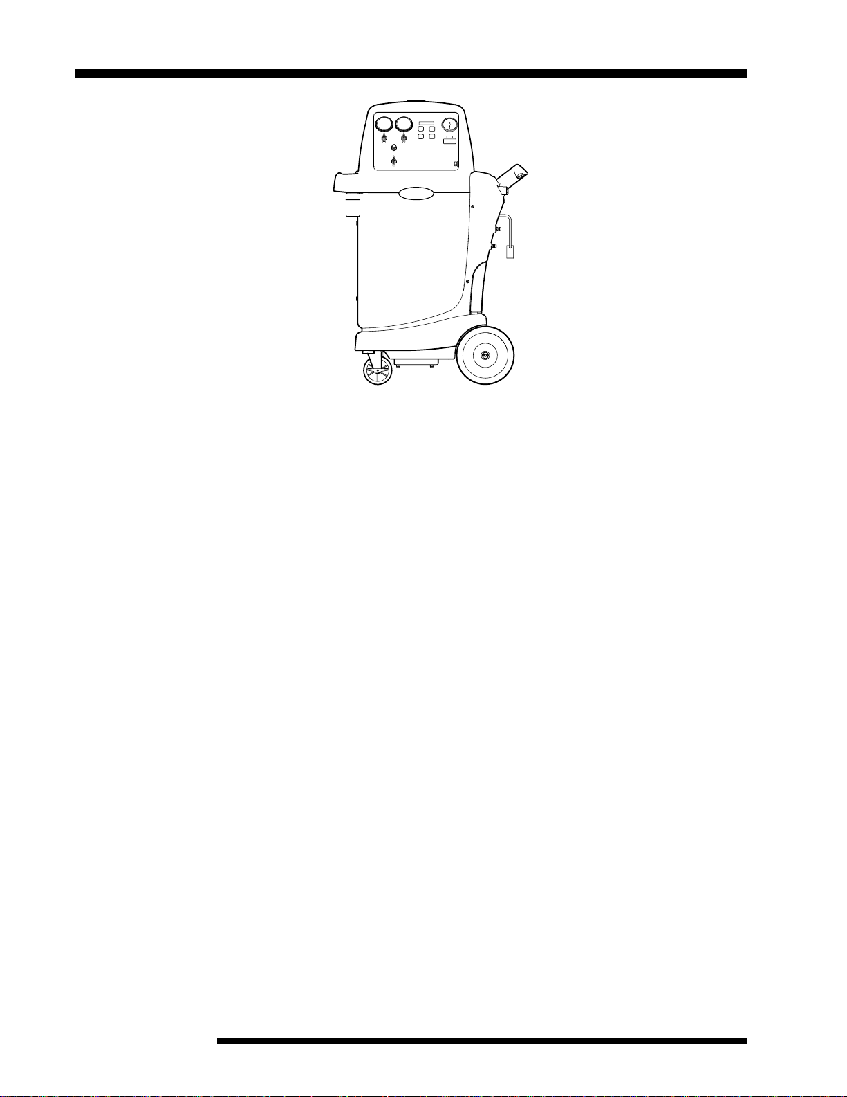
The 34134Z recovers, recycles, and recharges vehicle refrigerant in one
hookup. It is compatible with existing service equipment and standard service
procedures.
INST0999
Throughout this manual U.S. measurements are used with metric equivalents
in parenthesis.
Glossary of Terms
A/C System — The vehicle air conditioning system being serviced.
Hose Storage Fittings — When not in use, the R-134a service hose fittings
can be connected to these fittings for storage purposes.
Internal Storage Vessel (ISV) — The refillable refrigerant storage vessel
inside the unit.
Panel Valves — The high-side and low-side valves on the control panel, when
described together.
Service Couplers — The couplers on the service hoses used to connect the
hoses to the A/C system or to a source tank.
2
© 2003 SPX Corporation
Page 5
Component Identification and Location
Introduction
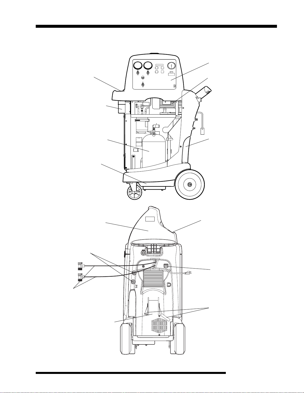
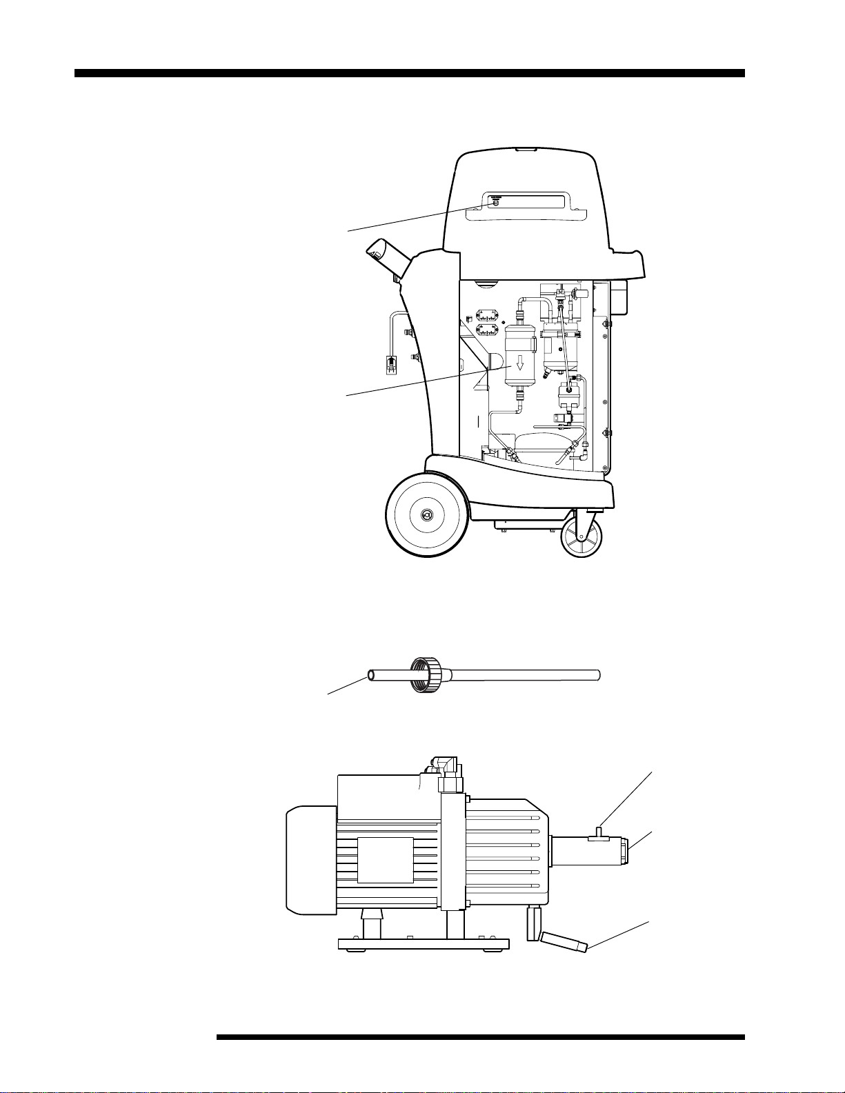
Unit Front View
Tool Tray
Oil Inject Bottle
Internal Storage
Vessel
Weight Scale
Unit Side View
Control Panel
Vacuum Pump
Oil Drain Bottle
INST1000
Hose Storage Fittings
Service Hoses
Source Tank Compartment
Hood
Operating Manual Compartment
Power Cord
Source Tank Strap
INST1006
Recover/Recycle/Recharge Unit
3
Page 6
Introduction
Component Identification and Location
Unit Back View
Circuit Breaker
Filter-Drier
contd.
Vacuum Pump
(Location shown on previous page)
Oil Filler Cap and Tube
(Included in accessory kit)
INST1001
Oil Fill Port
Oil Sight Glass
INST1003
Oil Drain Port
4
© 2003 SPX Corporation
Page 7
Introduction
Component Identification and Location
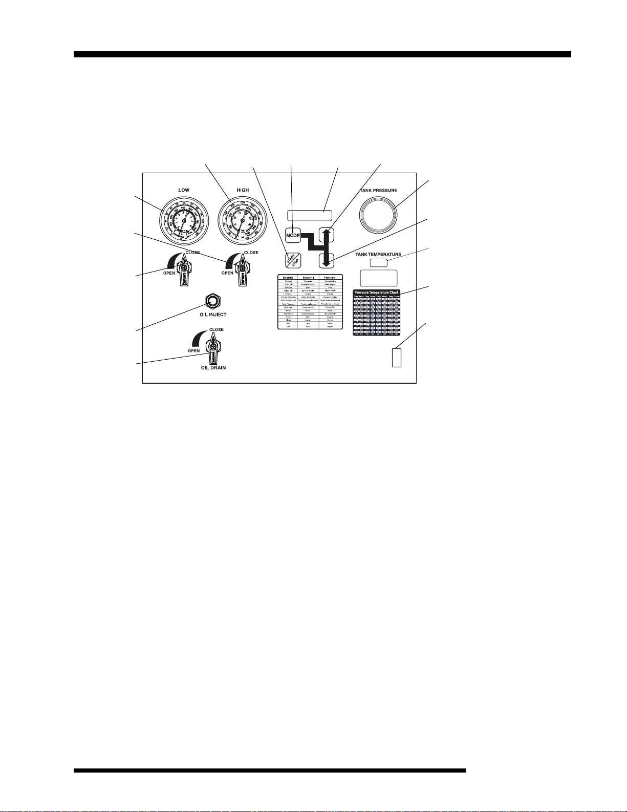
Control Panel
Low-Side
Gauge
High-Side
Panel Valve
(Valves shown
closed)
Low-Side Panel
Valve
Oil Inject
Button
Oil Drain
Valve
High-Side
Gauge
Start/Stop
Key
Mode
Key
contd.
Display
Screen
Up
Arrow
ISV Pressure
Gauge
Down
Arrow
ISV
Temperature
Display
Temp/Pressure
Chart
ON/OFF
Power Switch
I
O
Low-Side Valve — controls the flow between the A/C system’s low side and the unit.
High-Side Valve — controls the flow between the A/C system’s high side and the unit.
Low-Side Gauge — shows the A/C system’s low-side pressure.
High-Side Gauge — shows the A/C system’s high-side pressure.
Oil Inject Button — injects new oil into A/C system.
Display Screen — displays operational information.
Keypad — contains the following keys for performing specific functions:
MODE — chooses function options.
START/STOP — starts, stops, or exits a function.
UP/DOWN Arrows — adjusts operating parameters.
ISV Pressure Gauge — shows the pressure inside the internal storage vessel.
Oil Drain Valve — drains the A/C system’s oil into the oil drain bottle.
ISV Temperature Display — displays the temperature inside the internal storage vessel.
Temp/Pressure Chart — displays the pressure of a refrigerant at a given temperature.
Recover/Recycle/Recharge Unit
5
Page 8
Initial Setup
WARNING
This manual contains important procedures concerning the setup, operation, and
maintenance of the unit. Read and follow all warnings at the beginning of this
manual. Do not operate the unit until you have read and entirely understand the
contents of this manual. If you do not understand any of the contents of this manual,
notify your supervisor.
If the operator cannot read these instructions, all instructions and safety precautions mu st
be read and discussed in the operator’s native language.
Unpacking the Accessory Kit
Unpack the accessory kit from the bag and remove the plastic packaging. The
accessory kit consists of the following:
l Vacuum pump oil, oil filler cap, and tube
l Plastic pouch containing a warranty card, applicable MSDS sheets, a
service center listing, and an envelope of MACS information.
l Low side tank adapter
Registering the Unit
To comply with federal law governing A/C system service, you must complete
and mail the MVAC Certification Form included in the accessory kit. You must
also make sure your technicians are certified with the Mobile Air Conditioning
Society (MACS). For more information, read the MACS information included in
the accessory kit, or visit the MACS web site at www.macsw.org.
To validate the warranty provided by SPX ROBINAIR, complete the warranty
card included in the accessory kit, and mail it within ten days from the
purchase date.
6
© 2003 SPX Corporation
Page 9
Initial Setup
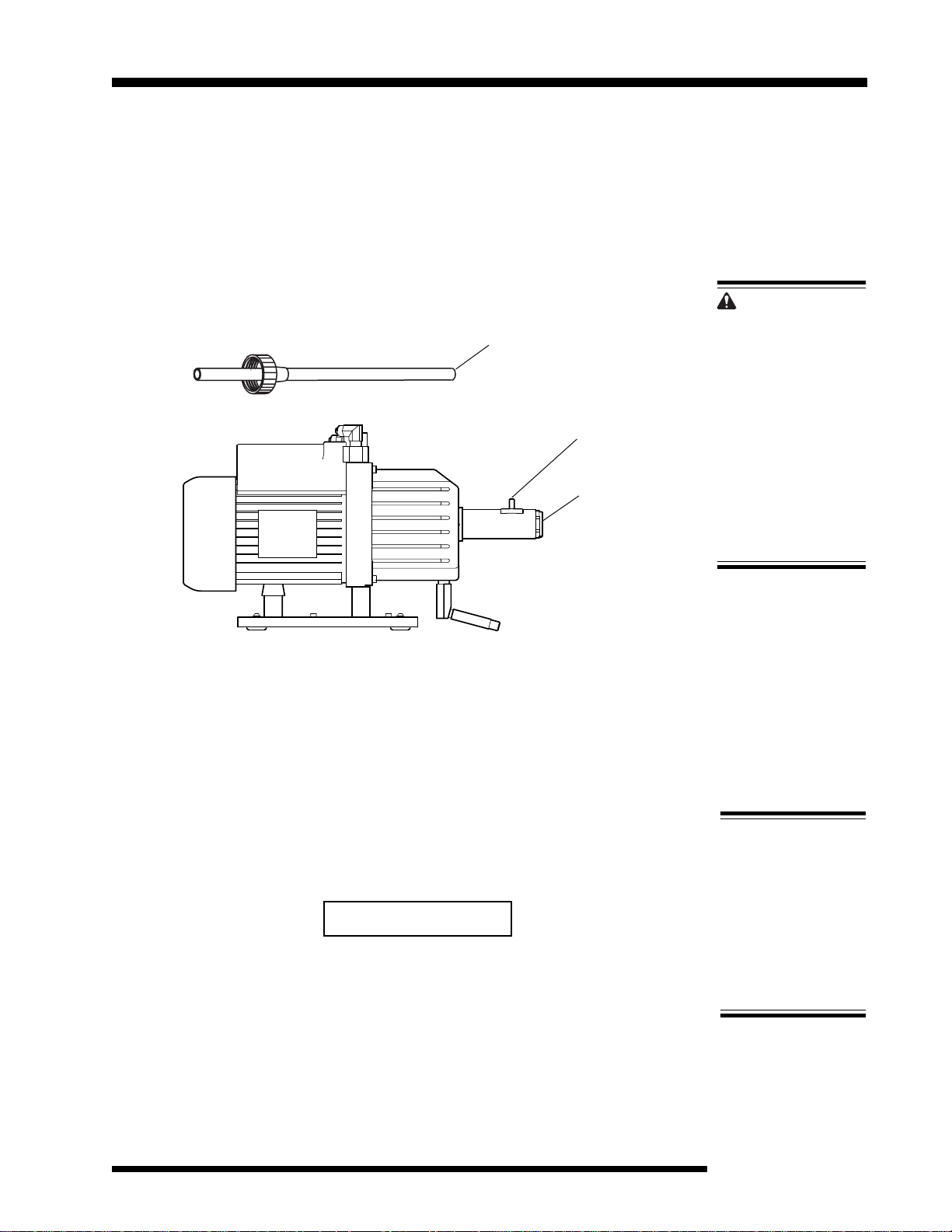
Adding Vacuum Pump Oil
After registering the unit, use the following steps to add oil to the vacuum
pump.
IMPORTANT: For maximum unit performance, change the vacuum pump
oil after every 10 hours of operation. (The unit will prompt a vacuum
pump oil change after every 10 hours of operation.
1. Plug the unit’s power cord into a correct voltage outlet.
Oil Filler Cap and Tube
(included in accessory kit)
Vacuum Pump
2. Remove the plastic plug from the oil fill port.
Oil Fill Port
Oil Sight Glass
INST1003
CAUTION!
Avoid using an
extension cord.
An extension
cord may
overheat and
cause fire. If you
must use an
extension cord,
use the shortest
possible cord
with a minimum
size of 14 AWG.
3. Attach the oil filler cap and tube to a vacuum pump oil bottle, and pour about
6 ounces (175 mL) of oil into the oil fill port.
4. Turn the unit’s power switch on.
5. On the control panel, verify both panel valves are open, and verify the
service couplers are disconnected from the vehicle. Screen will display:
CLEAR 02.00
6. Press Start/Stop key to start the vacuum pump.
Recover/Recycle/Recharge Unit
IMPORTANT!
The vacuum
pump is shipped
without oil in the
reservoir. To
avoid pump
damage, add oil
before starting
the pump.
7
Page 10

Initial Setup
Adding Vacuum Pump Oil
Note: The unit’s
weight default is in
pounds. To change
to kilograms:
1. Press the Up and
Down
arrow keys
at the same time.
UNITS LBS
will be displayed.
2. Press the Up or
Down
arrow key
to toggle to KG.
3. Press
Mode
key
until display reads
EXIT.
NOTE: At this time, the unit is also automatically evacuating all air from the unit.
7. With the vacuum pump running, slowly add oil until the level rises to the
center of the oil sight glass.
8. When the vacuum pump countdown reaches zero, the vacuum pump will
stop and the unit display will change to the recover function.
9. Replace the plastic plug in the oil fill port.
After adding oil to the vacuum pump, add refrigerant to the internal storage
vessel. Refer to the instructions on the next page.
contd.
8
© 2003 SPX Corporation
Page 11
Initial Setup
Adding Refrigerant to the Internal Storage Vessel
Add refrigerant to the internal storage vessel (ISV) after adding oil to the
vacuum pump. After the initial refrigerant fill, refill the ISV as necessary. (Refer
to
Adding Additional Refrigerant to the ISV
WARNING
Wear safety goggles when working with refrigerant. All hoses
may contain liquid refrigerant under pressure. Disconnect
hoses using extreme caution. Read and follow all warnings at
the beginning of this manual before operating the unit.
in this manual.)
Service Hoses
R-134a High-side
Hose
Storage Fitting
R-134a Low-side Hose
Storage Fitting
Source
Tank Strap
Source Tank
Compartment
INST1006
Unit Components - Side View
Recover/Recycle/Recharge Unit
9
Page 12

Initial Setup
Adding Refrigerant to the Internal Storage Vessel
1. Connect the low-side tank adapter (from the accessory kit) to the liquid
valve on the refrigerant source tank.
connect the tank adapter to the vapor valve.
R-134a Tank Adapter
2. Connect the service coupler of the low-side hose (blue) to the refrigerant
source tank.
3. Open the valve on the source tank, and place the tank upside down in the
source tank compartment. Secure the source tank in place by wrapping the
strap around the tank, and then fastening the strap.
4. The screen should display RECOVER XX.XXLBS. If it does not, scroll
through the functions by pressing the Mode key until RECOVER XX.XXLBS
is displayed.
NOTE: If using a refillable source tank,
contd.
5. Press the Arrow keys to adjust the recover weight to 15 lbs. (7 kg).
6. On the control panel, open the low-side valve; verify the high-side valve is
closed.
Low-Side
Gauge
High-Side
Panel Valve
(Valves shown
closed)
Low-Side Panel
Valve
Oil Inject
Button
Oil Drain
Valve
High-Side
Gauge
Start/Stop
Key
Control Panel
Mode
Key
Display
Screen
Up
Arrow
I
O
ISV Pressure
Gauge
Down
Arrow
ISV
Temperature
Display
Temp/Pressure
Chart
ON/OFF
Power Switch
10
© 2003 SPX Corporation
Page 13

Initial Setup
Adding Refrigerant to the Internal Storage Vessel
7. Press the Start/Stop key. The internal storage vessel begins filling, and the
screen displays the amount of refrigerant being transferred to the internal
storage vessel.
8. The unit will automatically stop when 15 lbs. (7 kg) has been transferred to
the internal storage vessel. The display will flash between:
RECOVER XX.XXKG
and
DRAIN OIL
contd.
NOTE: Do not drain oil until the following steps are complete. Drain oil
instructions are at the bottom of this page.
9. Unstrap the source tank, remove it from its compartment, then close the
source tank valve.
10.
Disconnect the hose from the tank.
11.
Cap the source tank with its original tank cap. For storage, place the source
tank upright in the source tank compartment. Secure the source tank in
place by wrapping the strap around the tank, and then fastening the strap.
12.
Do the following to clear the service hoses:
a. Press Mode key to:
RECOVER XX.XXLBS
b. Press Start/Stop key to start hose clearing.
c. Watch the low-side gauge. When the gauge pressure reaches 10 in. Hg
(34 kPa) vacuum, press Start/Stop key to stop the clearing process.
13.
Close the low-side panel valve.
Drain Oil
1. On the control panel, open the oil-drain valve. Watch the oil drain into the
oil-drain bottle. It may take 30 seconds or more for the oil to start draining.
2. When oil stops draining, close the oil-drain valve.
Recover/Recycle/Recharge Unit
11
Page 14

Initial Setup
Changing the Temperature Scale (Fahrenheit or Celsius)
The temperature scale is set to Fahrenheit at the factory. Use the following
steps to toggle the temperature scale to Celsius.
1. Disconnect the unit’s power cord from the outlet.
WARNING
High voltage electricity inside the unit has a risk of electrical
shock. Disconnect the power before servicing the unit.
2. Remove the four screws that secure the top section of the unit’s protective
covering and remove the covering.
3. Locate the selector switch on the back of the tank temperature display.
Selector
Switch
INST1005
Control Panel — Inside, Back View
4. Change the position of the switch to change the temperature scale.
5. Replace the top section of the unit’s protective covering, and replace the
four screws that secure the covering.
12
© 2003 SPX Corporation
Page 15

Operation
WARNING
This manual contains important procedures concerning the setup, operation, and
maintenance of the unit. Read and follow all warnings at the beginning of this
manual. Do not operate the unit until you have read and entirely understand the
contents of this manual. If you do not understand any of the contents of this manual,
notify your supervisor.
If the operator cannot these instructions, all instructions and safety precautions must be
read and discussed in the operator’s native language.
Operating Guidelines
For best results when operating the unit, use the following guidelines along
with the operation instructions contained in this manual.
The recovery compressor is
•
A/C system to a partial vacuum only. Use the Vacuum function for a
minimum of 15 minutes to remove moisture from the A/C system. Refer to
Evacuating the A/C System
The unit includes a 3 cfm high vacuum pump for fast, thorough evacuation.
•
Change the vacuum pump oil after every 10 hours of vacuum pump use.
The unit displays a CHANGE OIL message as a reminder. Refer to
Changing the Vacuum Pump Oil
manual.
The unit is equipped with a circuit breaker button, located on the back of the
•
unit. If the circuit breaker trips, the unit will not function correctly and will
lose all power. If necessary, press the circuit breaker button to reset the
unit.
This unit should be operated between the ambient temperatures of
•
50–120° F (11–49° C). At temperatures exceeding 104° F (40° C), wait 10
minutes between recovery jobs.
Follow the SAE-J2211 recommended service procedure for the containment
•
of R-134a refrigerant.
During normal use, periodically inspect the unit for leaks. At a minimum,
•
inspect the unit every three months. Refer to
“Maintenance” section of this manual.
not
a vacuum pump. The compressor pulls the
in the “Operation” section of this manual.
in the “Maintenance” section of this
Checking for Leaks
in the
Recover/Recycle/Recharge Unit
13
Page 16

Operation
Operating Guidelines
During operation, any of the following messages may appear on the display
•
screen. If a message appears, immediately take the appropriate action.
CHANGE FILTER — This message appears after every 150 lbs. (68.0 kg) of
refrigerant has been recovered, indicating that the filter-drier needs to be
replaced. Refer to
of this manual.
NOTE: To avoid service delays, keep extra filter-driers on hand.
CHANGE OIL — This message appears after every 10 hours of vacuum
pump use. Refer to
nance” section of this manual.
DRAIN OIL — This message appears after recovering refrigerant from an
A/C system. For more information, refer to
the “Operation” section of this manual.
HIGH PRESSURE — This message appears if the internal storage vessel’s
pressure rises to 435 psig (30 bar) or higher. Let the unit cool down for 30
minutes. Then press the Mode key and the Up arrow key to clear the
message from the display screen. If the message does not clear, contact a
manufacturer-authorized service technician.
contd.
Replacing the Filter-Drier
Changing the Vacuum Pump Oil
in the “Maintenance” section
Draining the A/C System Oil
in the “Mainte-
in
OVERLOAD — This message appears if the weight of the internal storage
vessel reaches 43 lbs. (19.5 kg), or if the unit’s weight scale is damaged,
disconnected, or out of calibration. Immediately remove refrigerant from the
internal storage vessel. Then press the Mode key and the Up arrow key to
clear the message from the display screen. If the message does not clear,
contact a manufacturer-authorized service technician.
14
© 2003 SPX Corporation
Page 17

Recovering the A/C System Refrigerant
WARNING
Wear safety goggles when working with refrigerant. All hoses may contain liquid
refrigerant under pressure. Disconnect hoses using extreme caution. Read and
follow all warnings at the beginning of this manual before operating the unit.
Do not overfill the internal storage vessel. Overfilling may cause explosion and
serious personal injury or death. If the message OVERLOAD appears in the display
screen, the internal storage vessel is too full — remove refrigerant. If the message
HIGH PRESSURE appears in the display screen, let the unit cool down. If the
message does not clear, call an authorized service technician.
Do not recover or charge refrigerants into nonrefillable containers; use only
authorized refillable refrigerant containers. Do not overfill refrigerant containers.
Overfilling may cause explosion and serious personal injury or death.
Use the unit only with R-134a refrigerant. The unit is for recovering, recycling, and
recharging only R-134a refrigerant! Do not attempt to adapt the unit for another
refrigerant. Do not mix refrigerant types through a system or in the same container;
mixing of refrigerants will cause severe damage to the unit and the vehicle air
conditioning system.
Operation
Use the following steps to recover refrigerant from the vehicle’s A/C system.
1. Plug the power cord into a correct voltage outlet.
2. Turn the unit on.
3. Connect the service hoses to the A/C system. IMPORTANT: Connect the
red service hose to the A/C system’s high side and the blue service
hose to the low side.
Low-side
Gauge
High-side
Panel Valve
(Valves shown
closed)
Low-side
Panel Valve
High-side
Gauge
Start/Stop
Key
Mode
Key
Display
Screen
Up
Arrow
ISV Pressure
Gauge
Down
Arrow
ISV
Temperature
Display
Oil Inject
Button
Oil Drain
Valve
Recover/Recycle/Recharge Unit
ON/OFF
Power Switch
I
O
Control Panel
15
Page 18

Operation
Recovering the A/C System Refrigerant
4. Verify the oil drain valve is closed.
5. On the control panel, open both panel valves.
6. Press the Mode key until RECOVER X.XX LBS is displayed. (X.XX is the
amount of refrigerant capacity remaining in the internal storage vessel
[ISV].) Press the Start/Stop key to begin the recovery operation. Once
recovery begins, the RECOVER X.XXLBS changes from the amount in the
ISV to the amount being recovered.
Note: Verify there is enough capacity in the ISV by comparing the amount
of refrigerant in the A/C system to the amount on the display screen. The
amount in the A/C system should not be greater than the amount initially
displayed. If the amount is greater, charge some of the refrigerant from the
ISV into another refillable refrigerant tank.
IMPORTANT: The recovery compressor is
compressor pulls the A/C system to a partial vacuum only. You must use
the unit’s vacuum (evacuate) cycle to remove moisture from the A/C
system.
7. Watch the low-side gauge. When the pressure gauge reaches 10 in. Hg (34
kPa) vacuum, press the Start/Stop key. The display screen will indicate
how much refrigerant has been recovered, and then toggle between:
RECOVER XX.XXLBS
contd.
and
not
a vacuum pump. The
DRAIN OIL
NOTE: Drain oil after the recovery is complete; refer to the next page for
instructions regarding draining the oil.
8. Close both panel valves.
9. Wait 5 minutes, and then check the low-side gauge for a rise in pressure to
above zero. If there is a rise in pressure, repeat steps 5 through 9 as
needed until the pressure holds below zero for 2 minutes.
NOTE: If the pressure does not drop to 10 in. Hg (34 kPa) vacuum or
does not hold at 10 in. Hg (34 kPa) vacuum for at least 2 minutes, there
was freezing in the A/C system during recovery or the A/C system requires
repair. Repeat recovery or repair the A/C system as necessary.
After recovering all refrigerant from the A/C system, drain the A/C system oil.
Refer to the instructions on the next page.
Note: The displayed recovered weight can vary, depending on ambient
conditions, and should not be used as an indicator of scale accuracy.
16
© 2003 SPX Corporation
Page 19

Draining the A/C System Oil
After recovering the refrigerant from the A/C system, use the following steps to
drain the A/C system oil into the unit’s oil drain bottle.
Oil Drain Valve
Oil Drain Bottle
Operation
INST0984
Oil Drain Bottle Location
1. Make sure the oil drain bottle is empty. Remove, empty, and replace the oil
drain bottle if necessary.
NOTE: Dispose of oil according to current local regulations.
2. On the control panel, open the Oil Drain valve. Watch the oil drain into the
oil-drain bottle. It may take 30 seconds or more for the oil to start draining.
3. When the oil stops draining, close the Oil Drain valve.
4. Check the oil-drain bottle, and record the amount of oil removed. This is the
amount of oil that must be added to the A/C system after evacuating the A/C
system. Refer to step 2 in
manual.
5. Remove, empty, and replace the oil-drain bottle.
After draining the oil, evacuate the A/C system. Refer to the instructions on the
next page.
Replenishing the A/C System Oil
in this
Recover/Recycle/Recharge Unit
17
Page 20

Operation
Evacuating the A/C System
After recovering all refrigerant from the A/C system, draining the oil from the
system, and making repairs to the A/C system, use the following steps to
evacuate (VACUUM) the A/C system.
Wear safety goggles when working with refrigerant. All hoses may contain liquid
refrigerant under pressure. Disconnect hoses using extreme caution. Read and
follow all warnings at the beginning of this manual before operating the unit.
1. Verify the power cord is plugged into a correct voltage outlet, and the service
hoses are correctly connected to the A/C system. Important: Connect the red
service hose to the A/C system’s high side, and the blue service hose to
the low side.
2. On the control panel, open both panel valves.
3. Press the Mode key until the VACUUM screen displays. Press the Arrow
keys to set the amount of time desired for the vacuum. Fifteen minutes is
recommended, but the time may vary depending on environmental
conditions.
WARNING
VACUUM 15:00
NOTE: The display screen shows the time as mm:ss; where “mm”
represents minutes and “ss” represents seconds. Setting vacuum time to 0
(zero) will result in continuous vacuum pump operation.
IMPORTANT: Check gauges to verify they are equal to or less than zero
to prevent damage to the vacuum pump.
4. Press the Start/Stop key to begin the vacuum operation. Watch the vacuum
time on the display. The display will count down the amount of time it will
take to evacuate the A/C system.
VACUUM 00.00
5. When the evacuation is complete, the unit will automatically shut off, and
INJECT OIL will display on the screen.
6. Close both panel valves on the control panel.
7. Note the pressure on the low-side gauge and then wait 5 minutes.
8. After waiting 5 minutes, check the low-side gauge for a rise in pressure. If
the pressure remains stable, the evacuation is complete. If there is a rise in
pressure, the A/C system may need further repairs or the evacuation may
need to be repeated. Repeat the evacuation if necessary.
18
© 2003 SPX Corporation
Page 21

Replenishing the A/C System Oil
Before recharging the A/C system, replenish the A/C system oil. Add only the
amount of oil that was removed during recovery. If no oil was removed, do not
add any oil.
NOTES:
•
Refer to the A/C system manufacturer for correct oil replacement
procedures and oil specifications.
•
Replacing A/C system components may require
adding more oil. Refer to component manufacturer
for recommendations.
1. Refer to amount of oil that was removed during
recovery (see step 4 in
Oil
).
Draining the A/C System
Oil Inject
Bottle
Operation
2. Fill oil inject bottle with new oil:
O-ring
• Add 1–2 ounces (30–60 mL) more oil than was
recovered.
• Add any additional oil required by an A/C
component change.
3. Note the level of new oil in the bottle.
4. Place an o-ring around the oil inject bottle at the level
the oil will be at after replenishing the system.
For example, if the bottle’s oil level is at 4 ounces, and you need 1/2 ounce
of oil to replenish the A/C system, place the o-ring at the 3-1/2 ounce level.
5. Open the appropriate panel valve per the A/C system manufacturer’s
recommendations.
6. Push and hold the Oil Inject button until the system is replenished with the
desired amount of oil.
NOTE: To avoid getting air into the A/C system, do not remove all the oil from
the oil inject bottle.
Oil Drain
Bottle
To ensure the replenishment of oil into the A/C system, recharge the A/C
system, leaving the panel valves in the same position as the A/C system
manufacturer’s recommendations. Refer to instructions on the next page to
purge the air from the internal storage vessel prior to recharging.
Recover/Recycle/Recharge Unit
19
Page 22

Operation
Purging Air from the Internal Storage Vessel
Use the following steps to purge unwanted air from the internal storage
vessel.
Start/Stop
Key
Mode
Key
Display
Screen
Up
Arrow
ISV Pressure
Gauge
Down
Arrow
ISV
Temperature
Display
Temp/Pressure
Chart
I
O
1. On the control panel, note the internal storage vessel temperature in the
ISV temperature display.
NOTE: The ISV temperature display can show Fahrenheit or Celsius
degrees. Refer to
2. Use this temperature to find the correct refrigerant pressure on the
Temperature/Pressure Chart located in this manual or on the control panel.
3. Compare the pressure from the chart to the pressure shown on the unit’s
tank pressure gauge. If the pressure from the chart is lower than the gauge
pressure, the internal storage vessel contains air.
4. To purge the air from the internal storage vessel, press Mode until PURGE
AIR appears.
5.
Press and hold the START/STOP button until the gauge pressure drops to the
correct pressure from the chart. Then release the START/STOP button.
Changing the Temperature Scale
in this manual.
20
6. Wait 5 minutes to allow the temperature and pressure to stabilize. Check
the temperature and pressure again.
7.
If necessary, repeat the steps until the pressure is correct for the temperature.
After purging the air, recharge the system.
© 2003 SPX Corporation
Page 23

Recharging the A/C System Refrigerant
WARNING
Wear safety goggles when working with refrigerant. Hoses may contain liquid
refrigerant under pressure; disconnect hoses using extreme caution. Read and
follow all warnings at the beginning of this manual before operating the unit.
After replenishing the A/C system oil as necessary and purging the A/C
system, use the following steps to recharge the A/C system’s refrigerant.
NOTE: For maximum unit performance during recharging, make sure the
refrigerant level in the source tank is at least 3 lbs. (1.4 kg) more than the
amount required for recharging the vehicle being serviced.
1. Refer to the A/C system manufacturer’s service manual to determine the
required amount of refrigerant to recharge.
2. Verify the unit’s power cord is plugged into a correct voltage outlet, and the
service hoses are correctly connected to the A/C system. IMPORTANT:
Connect the red service hose to the A/C system’s high side and the
blue service hose to the low side.
3. Verify the unit is turned on.
Operation
IMPORTANT!
This unit is
designed for
R-134a systems.
Do not attempt to
adapt the unit for
another refrigerant
— system failure
will result!
4. On the control panel, press the Mode key until the CHARGE XX.XX
(XX.XX refers to the charge weight) screen displays. Use the Arrow keys to
program how much to charge. Refer to the vehicle manufacturer’s
specifications on the amount to charge.
5. Open the appropriate panel valve(s) per the A/C system manufacturer’s
specifications.
6. Press the Start/Stop key to begin charging. The screen displays the
amount of refrigerant being charged.
7. Watch the display screen. When the required amount appears, the screen
will toggle between CHARGE COMPLETE and the amount that has been
charged.
CHARGE COMPLETE
8. Close the panel valves.
and
CHARGE XX.XX
Recover/Recycle/Recharge Unit
21
Page 24

Operation
Recharging the A/C System Refrigerant
WARNING
Before starting the vehicle’s engine, verify the vehicle is in PARK or
NEUTRAL, with the emergency brake ON.
To prevent personal injury or death, never run a vehicle without adequate
ventilation in the work area.
9. Start the vehicle’s engine, turn the A/C system on for maximum cooling, and
do the following:
a. Watch the high-side and low-side gauges on the unit’s control panel.
Refer to the A/C system manufacturer’s service manual to determine
the correct pressures.
b. Check the evaporator outlet temperature to be sure the A/C system is
operating correctly. Refer to the A/C system manufacturer’s service
manual to determine the correct temperature.
contd.
NOTE: If the pressures and temperature are not correct, the A/C system
may still require repair. Complete the remaining steps, and then investigate
and make any repairs as necessary.
10.
Stop the vehicle’s engine.
11.
Open both panel valves until gauges equalize.
12.
Close the coupler valves, and disconnect the service hoses from the A/C
system.
13.
Do the following to clear the service hoses:
a. Press the Mode key and scroll to RECOVER XX.XX. Press the
Start/Stop key.
b. When the low-side gauge pressure reaches 10 in. Hg (34 kPa) vacuum,
press the Start/Stop key. All refrigerant should be removed from the
hoses.
c. Close the panel valves.
22
© 2003 SPX Corporation
Page 25

Maintenance
Adding Additional Refrigerant to the Internal Storage Vessel
Periodically, the internal storage vessel (ISV) will require additional refrigerant.
Use the following steps to add refrigerant to the ISV.
1. Connect the R-134a tank adapter to the liquid valve on the refrigerant
source tank.
2. Connect the service coupler of the low-side hose (blue) to the adapter.
NOTE: If using a refillable source tank, connect to the vapor valve.
3. Open the valve on the source tank, place the tank upside down in the
source tank compartment, and secure the source tank strap around the
tank.
4. Press the Mode key until RECOVER XX.XXLBS (KG) is displayed. (XX.XX
is the amount of refrigerant capacity remaining in the ISV.)
5. Press the Arrow keys to adjust to the desired recover weight.
Note: Although the display shows the refrigerant capacity remaining in the
ISV,
the ISV should not be filled to this level
. At least 9 lbs. (4 kg) of
refrigerant capacity should be available in the ISV after filling to allow
space for the next A/C recovery. Therefore, adjust the unit to fill the ISV to
a level at least 9 lbs. (4 kg)
less
than what the display shows as the
remaining refrigerant capacity.
6. On the control panel, open the low-side valve; verify the high-side valve is
closed.
7. Press the Start/Stop key. The ISV begins filling, and the screen displays
the amount of refrigerant being transferred to the ISV.
R-134a Tank
Adapter
8. The unit will automatically stop when the desired amount has been
transferred to the ISV. The display will flash between:
RECOVER XX.XXLBS
and
DRAIN OIL
NOTE: Drain oil after the internal storage vessel is filled.
9. Unstrap the source tank, remove it from its compartment, then close the
source tank valve.
10.
Disconnect the hose from the tank.
11.
Cap the source tank with its original tank cap. For storage, place the source
tank upright in the source tank compartment, and secure the source tank
strap around the tank.
Recover/Recycle/Recharge Unit
23
Page 26

Operation
Adding Additional Refrigerant to the Internal Vessel
12.
Do the following to clear the service hoses:
a. Press Mode key to:
RECOVER XX.XXLBS
b. Press Start/Stop key to start hose clearing.
c. Watch the low-side gauge. When the gauge pressure reaches 10 in. Hg
(34 kPa) vacuum, press Start/Stop key to stop the clearing process.
13.
Close the low-side panel valve.
Drain Oil
1. On the control panel, open the oil-drain valve. Watch the oil drain into the
oil-drain bottle. It may take 30 seconds or more for the oil to start draining.
2. When oil stops draining, close the oil-drain valve.
contd.
24
© 2003 SPX Corporation
Page 27

Maintenance
Changing the Vacuum Pump Oil
For maximum unit performance, change the vacuum pump oil after every 10
hours of operation. The unit keeps track of vacuum pump running time and
will notify the user on the display screen when it is time to change oil. For
optimum performance, use only Robinair Premium High Vacuum Oil. Use the
following steps to change the vacuum pump oil.
Oil Fill Port
Sight Glass
INST0983
Vacuum Pump
1. Remove the cap from the oil-drain port, and drain the oil into a suitable
container (16 ounces [474 mL)] or larger) for disposal according to current
federal, state, and local regulations.
Oil Drain Port
NOTE: Review current local, state, and federal statutes, cases, laws, and
regulations to determine the correct disposal procedure for pump oil. It is the
responsibility of the user to determine if a material is a hazardous waste at the
time of disposal. Ensure you are in compliance with all applicable laws and
regulations.
2. Replace the cap on the oil-drain port.
3. Remove oil fill cap.
4. Add 6 ounces of oil.
5. Verify panel gauges read less than 0.
6. Press Mode key until screen displays VACUUM XX.XX. Press Start/Stop
key.
7. With the vacuum pump running, slowly add oil until the level rises to the
center of the oil sight glass.
8. Press Start/Stop key.
9. Replace cap.
After changing the vacuum pump oil, reset the vacuum pump oil timer.
Recover/Recycle/Recharge Unit
25
Page 28

Maintenance
Resetting Oil Time
Every time the vacuum pump oil is changed, the vacuum pump oil timer
should be reset. Use the following steps to reset the oil timer.
1. Simultaneously press and hold the Up and Down arrow keys until the
display shows UNITS LBS (KG).
2. Press the Mode key until the screen displays OIL XXX (XXX is minutes).
3. Simultaneously press and hold the Up and Down arrow keys until the
screen displays OIL 600 (minutes).
4. Press Mode key until EXIT displays.
26
© 2003 SPX Corporation
Page 29

Maintenance
Replacing the Filter-drier
The filter-drier inside the unit removes acid, particulates, and moisture from
refrigerant during the recovery function. To provide adequate contaminant
and moisture removal, the filter-drier must be replaced after every 150 lbs.
(68 kg) of refrigerant recovered. The following will appear in the display:
CHANGE FILTER
Use the following steps to replace the filter-drier.
NOTE: For maximum unit performance, use only No. 34430 SPX/ROBINAIR
filter-drier. To avoid service delays, keep extra filter-driers on hand. Refer to
the Replacement Parts section of this manual.
1. Plug the power cord into a correct voltage outlet, and turn the unit on.
2. Verify the service hoses are NOT connected to a vehicle.
High-Side
Gauge
Low-Side
Gauge
High-Side
Panel Valve
Valves shown closed
Low-Side Panel
Valve
Oil Inject
Button
Oil Drain
Valve
Start/Stop
Key
Mode
Key
Display
Screen
Up
Arrow
I
O
Control Panel
3. On the control panel, open both panel valves.
4. Press the Mode key until RECOVER XX.XX displays on the screen.
ISV Pressure
Gauge
Down
Arrow
ISV
Temperature
Display
Temp/Pressure
Chart
ON/OFF
Power Switch
5. Press the Start/Stop key.
6. Watch the low-side gauge. When the gauge pressure reaches 10 in. Hg
(34 kPa) vacuum, close both panel valves.
7. Turn the unit’s power switch off.
8. Remove the unit’s power cord from the outlet.
Recover/Recycle/Recharge Unit
27
Page 30

Maintenance
Replacing the Filter-drier
High voltage electricity inside the unit has a risk of electrical shock. Disconnect the
power before opening the back door or servicing the unit.
9. Open the back door of the unit’s protective covering. To unlock the door,
turn the two screws 1/4 turn counterclockwise.
contd.
WARNING
FLOW
#
Filter-Drier
INST1001
Filter-drier Location
(Back View of Unit)
10.
Remove the strap, disconnect the fittings from the filter-drier, and remove
the filter-drier.
NOTE: Dispose of the filter-drier according to current federal, state, and
local regulations.
11.
Install the new filter-drier with the FLOW direction arrow pointing down,
tighten the fittings, and secure with the strap.
12.
Close and lock the back door of the unit’s plastic covering. To lock the
door, turn the two screws 1/4 turn clockwise.
After replacing the filter-drier, reset the filter-drier capacity. Refer to the
instructions on the next page.
28
© 2003 SPX Corporation
Page 31

Maintenance
Resetting the Filter-drier Capacity
The unit keeps track of the filter-drier’s remaining capacity. As the unit filters
refrigerant, the remaining capacity decreases from 150 lbs. (68 kg) to zero.
When the capacity reaches zero, the unit will display:
CHANGE FILTER
Use the following steps to reset the filter-drier’s capacity.
1. Plug the power cord into a correct voltage outlet, and turn the unit on.
2. Simultaneously press and hold the Up and Down arrow keys until UNITS
LBS (KG) appears on the display.
3. Press the Mode key until FILTER XXX appears on the display.
4. Simultaneously press and hold the Up and Down arrow keys until FILTER
150 LBS (68 KG) appears on the display.
5. Press the Mode key until EXIT displays.
6. Press the Start/Stop key to exit the diagnostics function.
The unit is now ready to begin counting down the capacity of the new filter-drier.
Recover/Recycle/Recharge Unit
29
Page 32

Maintenance
Checking for Leaks
Over time, fittings can loosen as the unit is used and moved. During normal
use, inspect the unit for leaks at a minimum of every three months (or as
specified by current federal, state, and local regulations). Use the following
steps to check the unit for leaks.
NOTE: The manufacturer does not reimburse for lost refrigerant.
1. Remove the power cord from the outlet.
High voltage electricity inside the unit has a risk of electrical shock. Disconnect
the power before opening the back door or servicing the unit.
2. Remove the four screws that secure the hood.
3. Remove the hood.
4. Open the back door of the unit’s protective covering, and lift the door off
the unit. To unlock the door, turn the two screws 1/4 turn counterclockwise.
WARNING
5. Remove the five screws that secure the front section of the unit’s
protective covering, and remove the covering.
6. Use a leak detector to trace all lines, and check all connections for
refrigerant leaks. Tighten any fittings or connections if a leak is indicated.
WARNING
DO NOT use compressed air to pressure test or leak test the unit. Some mixtures of
air and refrigerant are combustible at elevated pressures. These mixtures are
potentially dangerous and may result in fire or explosion.
7. Replace the unit’s protective covering as follows:
a. Replace the front section, and replace the five screws that secure the
covering.
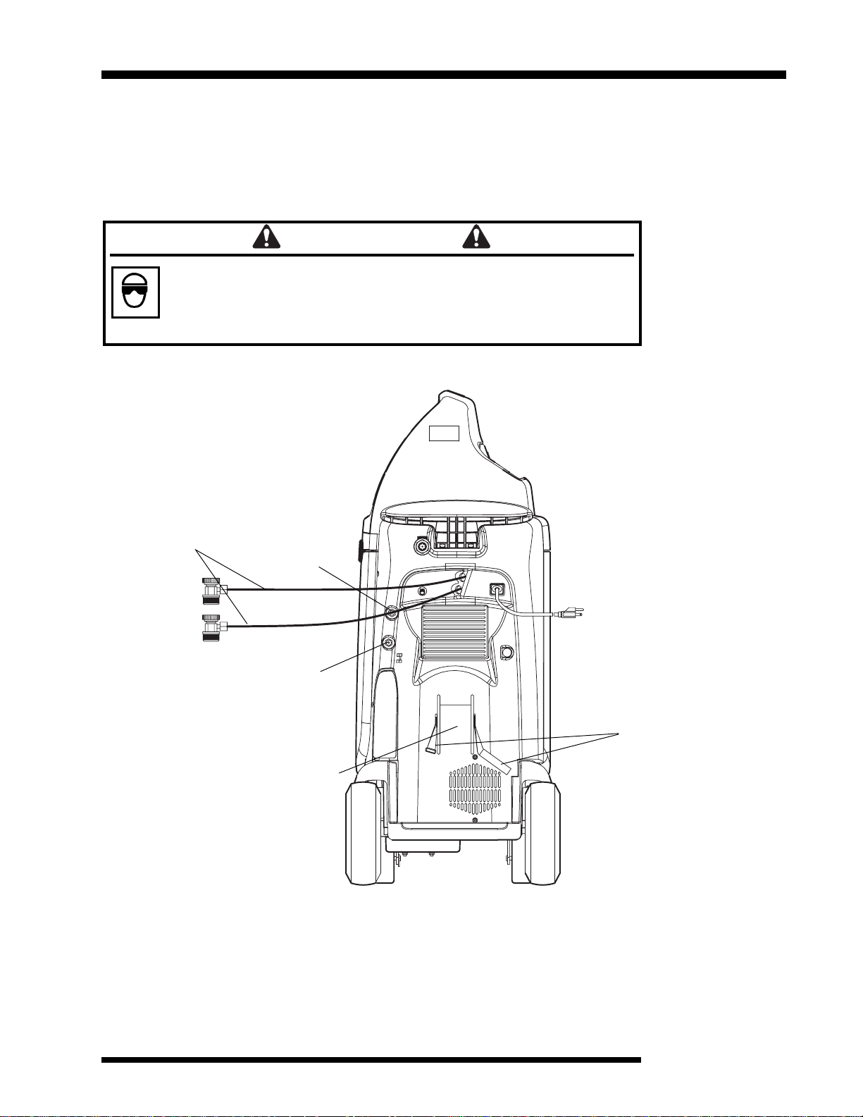
b. Replace, close, and lock the back door. To lock the door, turn the two
screws 1/4 turn clockwise.
c. Replace the hood and the four screws that secure the hood.
30
© 2003 SPX Corporation
Page 33

Maintenance
Calibrating the Weight Scale
The unit’s weight scale is calibrated at the factory and requires no further
calibration.
NOTE: If the message OVERLOAD appears on the display screen on the
control panel, the weight of the internal storage vessel is too high, or the unit’s
weight scale is damaged, disconnected, or out of calibration. Call a qualified
service technician.
Cleaning the Unit
On a regular basis, wipe off the unit with a clean cloth to remove grease, dust,
or other dirt.
Replacement Parts
The following is a list of replacement parts and accessories for the unit. For
ordering information, use the technical support telephone number listed on the
back cover of this manual.
Part No. Description
13204 Premium High Vacuum Pump Oil – Case of 4 Gallons
13203 Premium High Vacuum Pump Oil – Case of 12 Quarts
13201 Premium High Vacuum Pump Oil – Case of 12 Pints
17756 Oil Drain Bottle
18191A High-side Service Coupler
18190A Low-side Service Coupler
34430 Filter-Drier
522976 Blue Service Hose
522975 Red Service Hose
Recover/Recycle/Recharge Unit
31
Page 34

R-134a Temperature / Pressure Table
Conversion
Table
OZ. LBS.
0.5 0.03
1.0 0.06
1.5 0.09
2.0 0.13
2.5 0.16
3.0 0.19
3.5 0.22
4.0 0.25
4.5 0.28
5.0 0.31
5.5 0.34
6.0 0.38
6.5 0.41
7.0 0.44
7.5 0.47
8.0 0.50
8.5 0.53
9.0 0.56
9.5 0.59
10.0 0.63
10.5 0.66
11.0 0.69
11.5 0.72
12.0 0.75
12.5 0.78
13.0 0.81
13.5 0.84
14.0 0.88
14.5 0.91
15.0 0.94
15.5 0.97
16.0 1 lb.
Temperature Pressure
FC PSIG
45 7.2 40
47 8.3 42
49 9.4 44
51 10.6 47
53 11.7 49
55 12.8 51
57 13.9 54
59 15.0 56
61 16.1 59
63 17.2 61
65 18.3 64
67 19.4 67
69 20.6 70
71 21.7 73
73 22.8 76
75 23.9 79
77 25.0 82
79 26.1 85
81 27.2 88
83 28.3 92
85 29.4 95
87 30.6 99
89 31.7 102
91 32.8 106
93 33.9 110
95 35.0 114
97 36.1 118
99 37.2 122
101 38.3 126
103 39.4 131
105 40.6 135
107 41.7 139
109 42.8 144
111 43.9 149
113 45.0 154
115 46.1 158
117 47.2 163
119 48.3 169
121 49.4 174
123 50.6 179
Temperature Pressure
FC PSIG
125 51.7 185
127 52.8 190
129 53.9 196
131 55.0 202
133 56.1 207
135 57.2 214
137 58.3 220
139 59.4 226
141 60.6 232
143 61.7 239
145 62.8 246
147 63.9 252
149 65.0 259
151 66.1 266
153 67.2 274
155 68.3 281
157 69.4 288
159 70.6 296
161 71.7 304
163 72.8 312
165 73.9 320
167 75.0 328
169 76.1 336
171 77.2 345
173 78.3 354
175 79.4 363
177 80.6 372
179 81.7 381
181 82.8 390
183 83.9 400
185 85.0 410
187 86.1 419
189 87.2 430
191 88.3 440
193 89.4 450
195 90.6 461
197 91.7 472
199 92.8 483
201 93.9 495
202 94.4 500
32
© 2003 SPX Corporation
Page 35

Limited Warranty
Robinair Limited Warranty Statement
Rev. November 1, 2005
This product is warranted to be free from defects in workmanship, materials, and components for a
period of one year from date of purchase. All parts and labor required to repair defective products
covered under the warranty will be at no charge. The following restrictions apply:
1. The limited warranty applies to the original purchaser only.
2. The warranty applies to the product in normal usage situations only, as described in the Operating
Manual. The product must be serviced and maintained as specified.
3. If the product fails, it will be repaired or replaced at the option of the manufacturer.
4. Transportation charges for warranty service will be reimbursed by the factory upon verification of
the warranty claim and submission of a freight bill for normal ground service. Approval from the
manufacturer must be obtained prior to shipping to an authorized service center.
5. Warranty service claims are subject to authorized inspection for product defect(s).
6. The manufacturer shall not be responsible for any additional costs associated with a product
failure including, but not limited to, loss of work time, loss of refrigerant, cross-contamination of
refrigerant, and unauthorized shipping and/or labor charges.
7. All warranty service claims must be made within the specified warranty period. Proof-of-purchase
date must be supplied to the manufacturer.
8.
Use of recovery/recycling equipment with unauthorized refrigerants or sealants will void warranty.
Authorized refrigerants are listed on the equipment or are available through the Technical
•
Service Department.
The manufacturer prohibits the use of the recovery/recycling equipment on air conditioning (A/
•
C) systems containing leak sealants, either of a seal-swelling or aerobic nature.
This Limited Warranty does NOT apply if:
The product, or product part, is broken by accident.
•
The product is misused, tampered with, or modified.
•
The product is used for recovering or recycling any substance other than the specified refrigerant
•
type. This includes, but is not limited to, materials and chemicals used to seal leaks in A/C systems.
© 2003 SPX Corporation Recover/Recycle/Recharge Unit
Page 36

Visit our web site at
www.robinair.com
or
Call our Toll-Free
%
Technical Support Line at
800-822-5561
in the continental U.S. or Canada.
In all other locations, contact your local distributor. To help us serve
you, be prepared to provide the model number, serial number, and
date of purchase of your unit.
To validate your warranty, complete the warranty card attached to your
unit, and return it within ten days from date of purchase.
NATIONWIDE NETWORK OF AUTHORIZED SERVICE CENTERS
If your unit needs repair or replacement parts, contact the service
center in your area. For help in locating a service center, call the
toll-free technical support line or visit our website.
Due to ongoing product improvements,
we reserve the right to change design,
specifications, and materials without notice.
The 34134Z units are designed to meet all applicable agency certifications, including
Underwriter’s Laboratories, Inc., SAE Standards, and CUL.
Certain state and local jurisdictions dictate that using this equipment to sell refrigerant by
weight may not be permitted. We recommend charging for any A/C service by the job
performed.
This weight scale provides a means of metering the amount of refrigerant needed for optimum
A/C system performance as recommended by OEM manufacturers.
SPX Corporation
655 Eisenhower Drive
Owatonna, MN 55060-0995 USA
Technical Services: 1-800-822-5561
Fax: 1-412-690-2001
Customer Service: 1-800-533-6127
Fax: 1-800-322-2890
Web Site: www.robinair. com
523302 Rev. B (November 18, 2005) © 2003 SPX Corporation
 Loading...