

Page 1
○ ○○○○○○○○○○○○○○○○○○○○○○○○○○○○○○○○○○○○○○○○○○○○○○○○○○○○○○○○○○○○○○○○○○○○○○○○○○○○
Operating
M
anual
34134-2K—Refrigerant Recovery,
Recycling and Recharging Unit
for R-134a
34134-2K—Unidad de Recuperación,
Reciclado y Recarga para R-134a
(Page 21)
Page 2
LISTED
SAFETY DEFINITIONS: Follow all WARNING, CAUTION, IMPORTANT, and NOTE messages in this manual. These
messages are defined as follows: WARNING means you may risk serious personal injury or death; CAUTION means
you may risk personal injury, property damage, or serious unit damage; IMPORTANT means you may risk unit damage;
and NOTEs provide clarity and helpful tips. These safety messages cover situations ROBINAIR is aware of. ROBINAIR
cannot know, evaluate, and advise you as to all possible hazards. You must make sure all conditions and procedures do
not jeopardize your personal safety.
COPYRIGHT: No part of this manual may be reproduced, stored in a retrieval system, or transmitted in any form or by
any means (electronic, mechanical, photocopy, recorded, or otherwise) without the prior written permission of ROBINAIR.
DISCLAIMER: All information, illustrations, and specifications contained in this manual are based on the latest
information available at the time of publication. The right is reserved to make changes at any time without obligation to
notify any person or organization of such revisions or changes. Further, ROBINAIR shall not be liable for errors contained
herein or for incidental or consequential damages (including lost profits) in connection with the furnishing, performance, or
use of this material. If necessary, obtain additional health and safety information from the appropriate government
agencies and the vehicle, refrigerant, and lubricant manufacturers.
Recycling Equipment Design
Certified by Underwriters
Laboratories Inc.® for
Compliance with SAE-J2210
(1991) for HFC-134a
80S2
Refrigerant Recovery,
Recycling and Recharging Station
Series: 34134-2K
Refrigerants: R-134a
WARNINGS
ALLOW ONLY QUALIFIED PERSONNEL TO OPERATE THE UNIT. Before operating the unit, read and follow
the instructions and warnings in this manual. The operator must be a certified technician and must be familiar with
air conditioning and refrigeration systems, refrigerants, and the dangers of pressurized components. If the
operator cannot read English, operating instructions and safety precautions must be read and discussed in the
operator’s native language.
Si el operador no puede leer el inglés, las instrucciones de operación y las precauciones de seguridad deberán
leerse y comentarse en el idioma nativo del operador.
Si l’utilisateur ne peut lire l’anglais, les instructions et les consignes de sécurité doivent lui être expliquées dans sa
langue maternelle.
PRESSURIZED TANK CONTAINS LIQUID REFRIGERANT. Do not overfill the internal storage vessel because
overfilling may cause explosion and serious personal injury or death. Do not recover or charge refrigerants into
non-refillable containers; use only federally authorized refillable containers.
ALL HOSES MAY CONTAIN LIQUID REFRIGERANT UNDER PRESSURE. Contact with refrigerant may cause
personal injury. Wear correct protective equipment, including safety goggles. Disconnect hoses with extreme
caution.
HIGH VOLTAGE ELECTRICITY INSIDE THE UNIT HAS A RISK OF ELECTRICAL SHOCK. Exposure may
cause personal injury. Refer to the instruction manual for correct procedure when disconnecting the power.
TO REDUCE THE RISK OF FIRE, do not use the unit in the vicinity of spilled or open containers of gasoline or
other flammable substances. An extension cord may overheat and cause fire. If an extension cord is needed, use
the shortest possible cord with a minimum size of No. 14 AWG.
DO NOT BREATH REFRIGERANT. Exposure may cause personal injury, especially to the eyes, nose, throat, and
lungs. Use this equipment in locations with mechanical ventilation that provides at least four air changes per hour
or locate the equipment at least 18 inches above the floor. If accidental system discharge occurs, ventilate the
work area before resuming service.
USE THE UNIT WITH ONLY R-134a REFRIGERANT. The unit is for recovering, recycling, and recharging only
R-134a refrigerant! Do not attempt to adapt the unit for another refrigerant. Do not mix refrigerant types through a
system or in the same container; mixing of refrigerants will cause severe damage to the unit and the vehicle air
conditioning system.
DO NOT USE COMPRESSED AIR TO PRESSURE TEST OR LEAK TEST THE UNIT OR VEHICLE AIR
CONDITIONING SYSTEM. Some mixtures of air and R-134a refrigerant are combustible at elevated pressures.
These mixtures are potentially dangerous and may result in fire or explosion causing personal injury or property
damage.
Additional health and safety information may be obtained from refrigerant and lubricant manufacturers.
Page 3

Table of Contents
Introduction ...........................................................................................................2
Glossary of Terms ........................................................................................... 2
Operating Tips ................................................................................................. 3
Using The Control Panel .................................................................................4
Component Location and Identification ........................................................... 5
Set-Up Instructions................................................................................................ 6
Installing the Tank ...........................................................................................6
Setting up the Unit ........................................................................................... 7
Adding Refrigerant to the Unit Tank ................................................................ 8
Operating Instructions ...........................................................................................9
Recovering Refrigerant ................................................................................... 9
English
Evacuating the A/C System ............................................................................ 9
Air Purge ....................................................................................................... 10
Recharging the A/C System .......................................................................... 10
Maintenance Instructions .................................................................................... 11
Checking and Calibrating the Scale ..............................................................11
Replacing the Filter-Drier .............................................................................. 12
Checking and Resetting Filter Capacity ........................................................ 13
Checking for Leaks ....................................................................................... 13
Choosing the Temperature Scale ................................................................. 13
Troubleshooting Tips........................................................................................... 14
Vacuum Flow Diagram ........................................................................................ 15
Recover Flow Diagram........................................................................................ 16
Charge Flow Diagram ......................................................................................... 17
Español
Replacement Parts.............................................................................................. 18
Limited Warranty .................................................................................................19
Pressure/Temperature Chart ..................................................... Inside Back Cover
34134-2K Recovery, Recycling and Recharging Unit
1
Page 4

Introduction
This manual contains important safety procedures concerning the operation, use and maintenance of this product. Failure to follow the instructions
contained in this manual may result in serious injury. If you are unable to
understand any of the contents of this manual, please bring it to the
attention of your supervisor. Do not operate this equipment unless you have
read and understood the contents of this manual.
The 34134-2K Recovery, Recycling and Recharging unit is a one hook-up system
used for R-134a vehicles. This single-pass system is UL listed and meets the SAE
specifications for recycled refrigerant. It is also designed to be compatible with
existing service equipment and standard service procedures.
The 34134-2K is simple to operate and has many user-friendly features:
• Hose holder rack
• Large diameter wheels for easy relocation
• Plastic shroud that is resistant to abrasions and chemicals
• Handy manifold gauge set
GLOSSARY OF TERMS
A/C System The air conditioning system being serviced.
Unit The refrigerant recovery/recycling/recharging unit.
Unit Tank The refillable refrigerant tank included with this unit.
Source Tank A supply of refrigerant used to refill the unit tank.
2
© 2000 Robinair, SPX Corporation
Page 5

Introduction
Low Side Gauge
Low Side Valve
(Blue)
Low Side Port
INST0488
OPERATING TIPS
Center Port
High Side Gauge
High Side Valve
(Red)
High Side Port
Follow the SAE-J2210 recommended service procedures for the containment
of R-134a.
R-134a systems require special oils in place of the mineral oil used with R-12
systems. Refer to the A/C system manufacturer’s service manuals for oil
specifications.
Change the filter-drier when the display shows “CHANGE FILTER.” Follow the
instructions for changing the filter-drier.
Wait 10 minutes between recovery jobs when temperatures exceed 120°F / 49°C.
CAUTION!
to avoid cross-contamination with R-12 systems. Do not attempt to adapt your
unit for another refrigerant type—system failure will result!
R-134a systems have special fittings (per SAE specifications)
34134-2K Recovery, Recycling and Recharging Unit
3
Page 6
Introduction
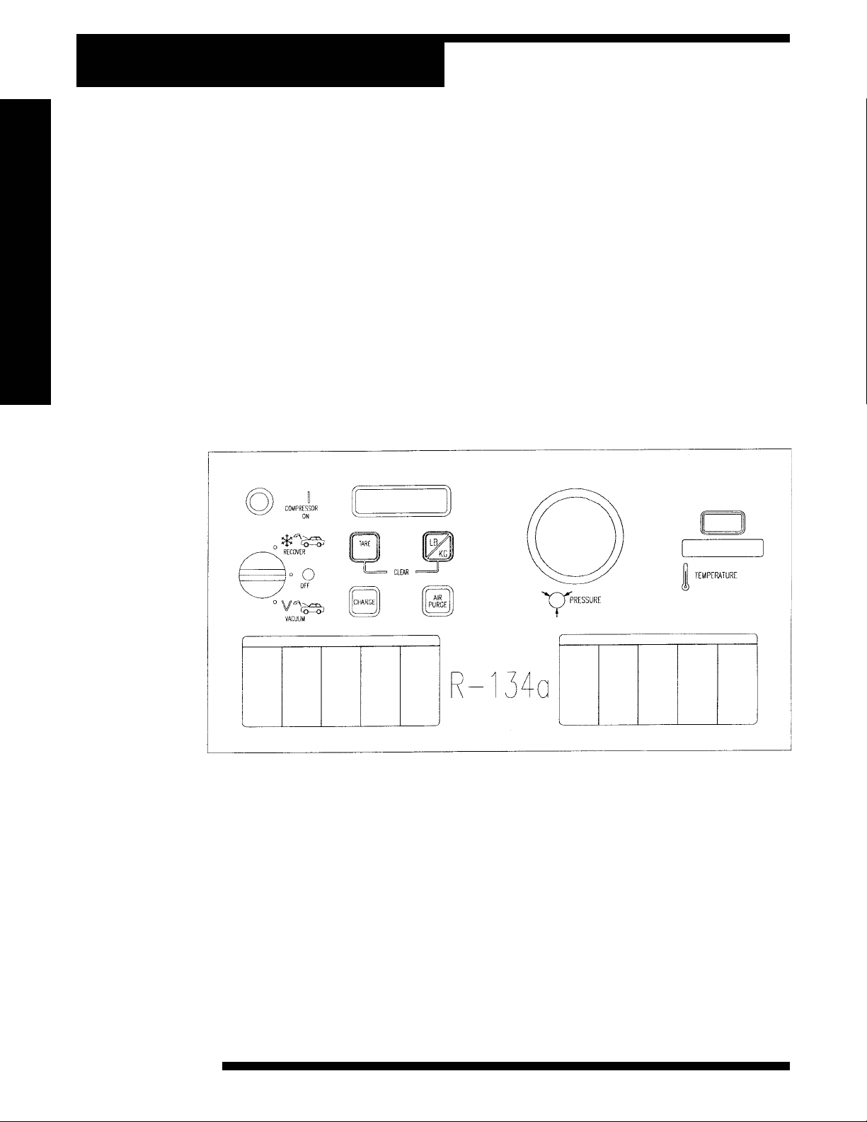
USING THE CONTROL PANEL
The control panel has the following specific operating functions:
1. RECOVER/VACUUM Switch — Starts the recovery or vacuum process.
2. TARE Button — Zeros the display weight prior to recovery or charging.
3. LB/KG Button — Toggles between the weight measurement units.
4. CHARGE Button — Controls the charging process.
5. AIR PURGE Button — Controls the air purge process.
6. TEMPERATURE Display — Indicates tank temperature.
7. COMPRESSOR ON Light — Indicates compressor has started.
8. PRESSURE Gauge — Indicates the tank pressure.
9. CONTROL BOARD Display — Indicates refrigerant weight and error messages.
4
INST 0754
© 2000 Robinair, SPX Corporation
Page 7

Introduction
COMPONENT LOCATION AND IDENTIFICATION
Rear ViewFront View
Power
Receptacle
Heater
Outlet
Heater
Circuit Breaker
Manifold valves
Access Port
Oil Drain Valve
Oil Drain Bottle
Scale Assembly
INST 0755
34134-2K Recovery, Recycling and Recharging Unit
INST 0756
5
Page 8

Set-Up Instructions
INSTALLING THE TANK
The new tank comes with a dry nitrogen charge of 10 to 15 psi (4.9 to 7.4 bar) to
keep it clean and dry during shipment. To install the new tank, you will need to:
1. Purge its nitrogen charge by opening either valve on the tank, vent the pressure
to the atmosphere, then close the valve.
2. Place the unit tank on the scale platform on the back of the unit (see illustration
on page 5 for location). Then attach the tank strap to the tank handle.
3. Attach the temperature probe at the approximate location shown below.
CAUTION! Some tanks have slightly different valve configurations. Be sure to
connect the VAPOR hose to the GAS (vapor) valve and connect the LIQUID hose to
the LIQUID valve.
Temperature
Probe
INST 0494
Valve ports
tt
t
tt
5cm (2 in.)
ss
s
ss
Valves:
Blue Liquid Valve
Red Vapor Valve
6
© 2000 Robinair, SPX Corporation
Page 9

Set-Up Instructions
SETTING UP THE UNIT
To set up the unit to an R-134a vehicle:
1. Attach the 60" blue hose to the low side port of the manifold.
2. Attach the 60" yellow hose to the center port of the manifold.
3. Attach the 60" red hose to the high side port of the manifold.
4. Place the assembled manifold onto the manifold support bracket on the back
of the unit.
5. Attach the yellow hose from the manifold to the access port on the back of the
unit.
6. Connect the tank adapter (included with the unit) to the LIQUID port (blue)
of the tank. Attach the blue low side hose from the manifold to the tank
adapter.
NOTE:
adapter could result in damage to the compressor, voiding the manufacturer's
warranty.
10. Open both valves on the tank.
11. Open the service coupler on the blue low side hose.
12. Verify that the RECOVER/VACUUM switch (see page 4 for switch location)
13. Attach the power cord to the back of the unit (see page 5) and connect to the
14. Turn the switch on the control panel to VACUUM.
15. Allow the unit to run for 5 minutes.
16. Turn the RECOVER/VACUUM switch to OFF.
17. Close the high side manifold valve (red).
Use ONLY the tank adapter included with this unit. Use of any other
7. Attach the red vapor hose from the back of the unit to the GAS (red vapor)
valve on the tank.
8. Attach the air purge hose to the air purge fitting on the unit tank.
9. Open both valves on the manifold.
is in the OFF position.
correct voltage outlet on the vehicle.
18. Close the service coupler valve on the blue low side hose.
19. Close the LIQUID valve (blue) on the tank.
20. Disconnect the service coupler from the tank adapter.
21. Remove the tank adapter from the tank.
22. Attach LIQUID hose from the back of the unit to LIQUID port on the tank.
Open the LIQUID valve on the tank.
23. Reconnect the tank adapter to the hose holder for storage.
34134-2K Recovery, Recycling and Recharging Unit
7
Page 10

Set-Up Instructions
ADDING REFRIGERANT TO THE UNIT TANK
With the tank in place on the unit, add refrigerant from a source tank to the unit
tank using the following steps:
1. Connect the tank adapter to the LIQUID valve on the source tank. Attach the
blue low side service coupler to the tank adapter.
NOTE:
result in damage to the compressor, voiding the manufacturer's warranty.
2. Open the service coupler valve. Open the LIQUID valve on the source tank.
NOTE:
transfer liquid.
3. Press the TARE button (see page 4 for button location) on the control panel to
4. Turn the control panel switch to RECOVER. Monitor the display until 15 lbs.
5. Close the blue LIQUID valve on the source tank. Allow the unit to run for 5
6. Turn the RECOVER/VACUUM switch to OFF.
7. Close both manifold valves (see page 5 for manifold location).
8. Disconnect the service coupler from the tank adapter.
Use ONLY the tank adapter included with this unit. Use of any other could
Disposable tanks have only one valve and must be turned upside down to
zero the tare weight.
(6.8 kg) have been transferred.
minutes to clear the hoses.
9. Remove the adapter from the tank.
10. Reconnect the tank adapter to the hose holder for storage.
8
© 2000 Robinair, SPX Corporation
Page 11

Operating Instructions
RECOVERING REFRIGERANT
Use the following steps to take refrigerant out of a vehicle:
1. Connect the unit’s 60" (1.5m) red high side hose with the service coupler to
the high side fitting of the A/C system, then open the service coupler valve.
2. Connect the unit’s 60" (1.5m) blue low side hose with the service coupler to
the low side fitting of the A/C system, then open the service coupler valve.
3. Check the manifold gauges — both should register above zero. If there is no
system pressure, there is no refrigerant in the system to recover.
4. Be sure the oil drain valve (see page 5 for oil drain valve location) is closed.
5. Open both manifold valves.
6. Verify both tank valves are open.
7. Plug the unit into the correct voltage outlet.
8. Turn the control panel switch to RECOVER. Recover refrigerant until the low
side manifold gauge reads 13 in. Hg (0.44 Bar).
9. Close both manifold valves.
10. Turn the RECOVER/VACUUM switch to OFF.
11. Wait 5 minutes. Monitor the manifold gauges for a pressure rise above zero. If
a rise occurs, repeat steps 5 – 10.
CAUTION!
depressurize the oil separator.
12. Be sure the oil catch bottle is empty, then slowly open the oil drain valve, and
drain the oil into the oil catch bottle. This oil was removed from the A/C
system during recovery. When all the recovered oil has completely drained,
close the valve and record the amount of oil in the bottle.
The A/C system is empty. Make any repairs at this time.
Drain the oil from the separator only after each recovery. Do not
EVACUATING THE A/C SYSTEM
To ensure complete evacuation of the A/C system, use the following steps:
1. With the high side and low side hoses connected to the A/C system, open both
manifold valves.
2. Verify both tank valves are open.
3. Turn the control panel switch to VACUUM. Follow the manufacturer's
recommendations for evacuation time.
4. Turn the RECOVER/VACUUM switch to OFF.
5. Wait 5 minutes. Monitor the manifold gauges. Any rise indicates a leak in the
A/C system. Locate and repair. Repeat steps 3 – 5 until there is no longer a
rise on the gauges.
34134-2K Recovery, Recycling and Recharging Unit
9
Page 12

Operating Instructions
AIR PURGE
!
The gauge on the control panel shows when to purge air from the tank. To purge
non-condensables:
1. Check the TEMPERATURE display (see page 4) to find the temperature of
the refrigerant in the unit tank.
2. Use this temperature to find the correct pressure for the refrigerant on the
appropriate pressure/temperature chart on the control panel.
3. Compare the pressure from the chart to the reading on the tank pressure
gauge.
4. If the pressure exceeds the target pressure by more than 10 psi (0.7 Bar), press
the air purge button for approximately 30 seconds.
5. Check tank pressure and repeat steps as necessary.
!
RECHARGING THE A/C SYSTEM
To recharge A/C system:
1. Connect the high side and low side hoses to the A/C system according to its
manufacturer's recommendations for charging. Open appropriate service
coupler and manifold valve(s).
2. Verify both tank valves are open.
3. Press TARE button until “00.00” weight is displayed.
4. Determine the amount of charge needed from the vehicle nameplate. Press
and hold the CHARGE button until the desired weight charge is indicated on
the display. Release the CHARGE button.
5. Close both manifold valves.
6. Start the vehicle's engine and turn on the A/C system for maximum cooling.
Let it run until the gauge pressure readings stabilize. Compare the gauge
readings with the system manufacturer's specifications.
7. Check the evaporator outlet temperature to be sure that the A/C system is
operating correctly. Refer to the system manufacturer's specifications for the
correct temperature.
8. Turn off the vehicle's engine.
9. Close the high side coupler valve, then disconnect the high side hose from the
A/C system.
10. Restart the vehicle, then open both valves on the manifold. Refrigerant from
both hoses will be drawn quickly into the A/C system through the low side
hose.
11. Close the low side coupler valve, then disconnect the low side hose from the
A/C system.
12. Turn off the vehicle engine.
13. Close both manifold valves.
NOTE:
from the temperature probe not to interfere with temperature probe accuracy.
If using the optional heating blanket, make sure the blanket is far enough away
10
© 2000 Robinair, SPX Corporation
Page 13

CHECKING AND CALIBRATING THE SCALE
To check and calibrate the unit’s scale:
1. Remove the tank from the platform.
Maintenance
2. Press the TARE button (see page 4) until the display reads “00.00.”
3. Press the TARE button once more. The display reads “TOTAL” and “0+ .10.”
4. Place a known weight on the scale. The display will show the known weight
“+ .04 LB/.02 KG.”
5. If the display does not, recalibrate the scale.
6. To recalibrate, press the TARE and LB/KG buttons simultaneously to access
“DIAGNOSTICS.”
7. Press the TARE button until the display shows “CALIBRATION.”
8. Press LB/KG. Press YES (TARE) to continue or NO (LB/KG) to return to
main menu.
9. With no weight on the platform, press LB/KG. The display shows “30 LB/15
KG.” Place the indicated weight on the platform.
NOTE:
10. Press LB/KG. “PLEASE WAIT” shows on the display for approximately 10
11. Reverify scale accuracy.
This weight must be EXACT for accurate scale calibration.
seconds.
IMPORTANT!
You must have a
known weight of
15KG
(30LB + .01)
+.005
34134-2K Recovery, Recycling and Recharging Unit
11
Page 14

Maintenance
REPLACING THE FILTER-DRIER
The filter-drier on this unit is designed to trap acid, and particulates and is formulated to remove moisture from the refrigerant. Typically, you can recover up to
300 pounds of refrigerant between filter changes.
CAUTION!
34430). All performance tests and claims are based on using this
specially-blended filter-drier. Use of any other may affect performance
results.
For best results, use a Robinair filter-drier (part no.
WARNING
Steps 1 – 5 are critical to avoid possible hazardous release of refrigerant!
Filter-Drier
12
INST 0757
1. Make sure both tank valves and manifold valves are open.
2. Make sure the service couplers are closed.
3. Turn control panel switch to RECOVER.
4. Monitor manifold gauges until pressure reads below zero.
5. Turn RECOVER/VACUUM switch to OFF.
6. Remove filter by unscrewing nuts located at each end of the filter. Dispose of
the old filter according to all local and state regulations.
7. Inspect the condition of the gaskets inside the copper tubes that are connected
to the filter. Install new filter and hand tighten.
8. Turn the control panel switch to VACUUM for 5 minutes.
9. Turn RECOVER/VACUUM switch to OFF.
NOTE:
Following filter-drier replacement, the filter capacity must be reset.
© 2000 Robinair, SPX Corporation
Page 15

Maintenance
CHECKING AND RESETTING FILTER CAPACITY
The filter-drier removes contaminants from the refrigerant. To check and reset the
filter capacity:
1. Turn the RECOVER/VACUUM switch on the control panel to OFF.
2. Press LB/KG and the TARE buttons (see page 4 for button locations) simultaneously to access “DIAGNOSTICS.”
3. Press the TARE button until the display reads “FILTER CAPACITY.”
4. Press the LB/KG button. The display will show the filter capacity remaining in
the selected weight measurement.
5. To reset the capacity, press the TARE and LB/KG buttons simultaneously.
The display will show “300 LB/136 KG” remaining.
6. Press any button to exit “DIAGNOSTICS.”
CHECKING FOR LEAKS
Every three months, or as specified by local or state laws, you should check your
unit for leaks. To check for leaks:
1. Disconnect the power cord from the outlet.
2. Remove the shroud by removing the threaded screws at the back of the unit.
IMPORTANT!
Inspect the unit
periodically for
leaks. The manufacturer does not
reimburse for
lost refrigerant.
3. Use a leak detector to probe all fitting connections for refrigerant leaks.
Tighten fittings if a leak is indicated.
4. Reassemble the shroud to the unit, replacing all screws.
CHOOSING THE TEMPERATURE SCALE
The temperature scale may be changed from Fahrenheit or Centigrade using the
following procedure.
1. Disconnect the power cord from the outlet.
2. Remove the shroud by removing the threaded screws at the back of the unit.
3. A small selector switch is located on the back of the thermometer. Change the
position of the switch to change the temperature scale from either Fahrenheit
or Centigrade.
4. Reassemble the shroud to the unit, replacing all screws.
34134-2K Recovery, Recycling and Recharging Unit
13
Page 16

Troubleshooting Tips
RECOVERY AND VACUUM OPERATION
Compressor does not start or stop prematurely
Problem: No power.
Solution: Check for power at plug or outlet.
Problem: **OVERLOAD** is displayed.
Solution: Move refrigerant from unit tank to approved refrigerant storage
tank. See RECHARGING A/C SYSTEM.
Problem: HIGH PRESSURE is displayed.
Solution: Be sure tank valves are open and hoses are correctly connected
to the unit tank.
Problem: **SCALE** is displayed.
Solution: The scale is damaged, disconnected, out of calibration or over-
loaded.
Runs but gauges won't indicate 13 in Hg (0.44 BAR)
Problem: Oil drain valve open.
Solution: Close the oil drain valve.
Problem: Leak in vehicle system.
Solution: Locate and repair all system leaks.
Problem: Manifold valves not open.
Solution: Open valves.
14
© 2000 Robinair, SPX Corporation
Page 17
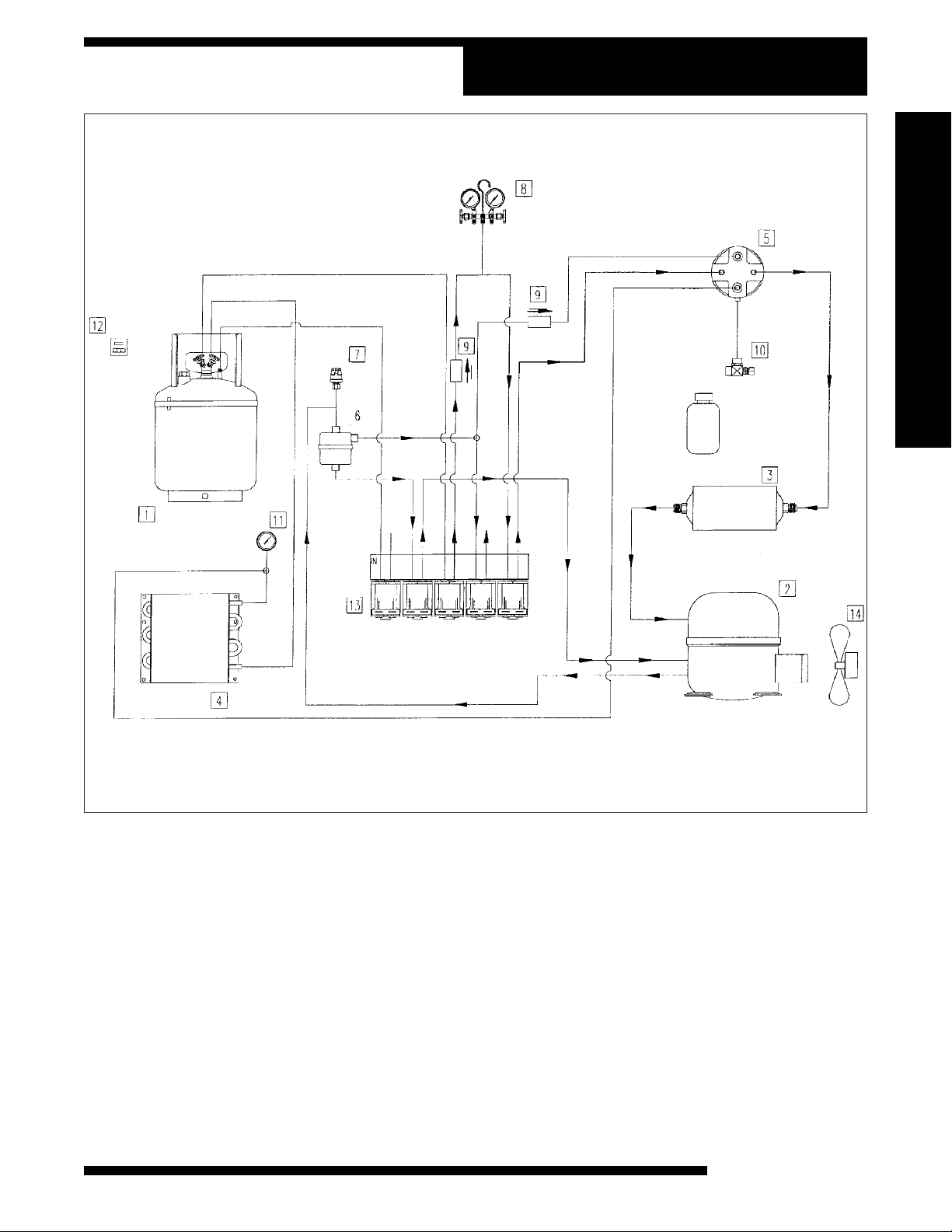
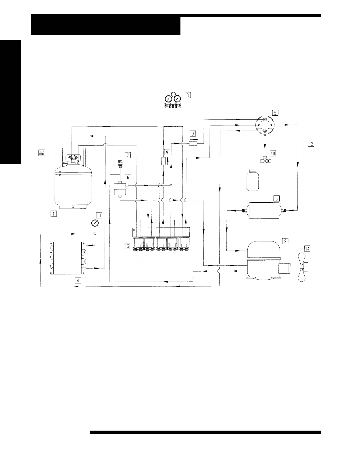
Vacuum Flow Diagram
TO LOW SIDE TO HIGH SIDE
INST 0748
1. Refrigerant Tank
2. Compressor
3. Filter
4. Condenser Coil
5. Accumulator
PURGE
OIL RETURN
CHARGE
VACUUM
RECOVER
6. Oil Separator
7. Pressure Switch
8. 2-Way Manifold
9. Check Valve
10. Oil Drain Ball Valve
11. Pressure Gauge (Air Purge)
12. Thermometer F°/C°
13. Solenoid Block
14. Fan
34134-2K Recovery, Recycling and Recharging Unit
15
Page 18
Recover Flow Diagram
TO LOW SIDE TO HIGH SIDE
16
1. Refrigerant Tank
2. Compressor
3. Filter
4. Condenser Coil
5. Accumulator
PURGE
OIL RETURN
CHARGE
VACUUM
RECOVER
6. Oil Separator
7. Pressure Switch
8. 2-Way Manifold
9. Check Valve
10. Oil Drain Ball Valve
INST 0749
11. Pressure Gauge (Air Purge)
12. Thermometer F°/C°
13. Solenoid Block
14. Fan
© 2000 Robinair, SPX Corporation
Page 19

Charge Flow Diagram
TO LOW SIDE TO HIGH SIDE
PURGE
INST 0750
1. Refrigerant Tank
2. Compressor
3. Filter
4. Condenser Coil
5. Accumulator
34134-2K Recovery, Recycling and Recharging Unit
6. Oil Separator
7. Pressure Switch
8. 2-Way Manifold
9. Check Valve
10. Oil Drain Ball Valve
OIL RETURN
CHARGE
VACUUM
RECOVER
11. Pressure Gauge (Air Purge)
12. Thermometer F°/C°
13. Solenoid Block
14. Fan
17
Page 20

Replacement Parts List
The following is a list of replacement parts and accessories you may need to service
or maintain your unit. We suggest you keep several filter-driers on hand so you will
always be able to change them and complete any recycling job that is in progress.
Component 110-Volt
Filter-Drier 34430
Low Side Service Coupler 18190A
High Side Service Coupler 18191A
60 in. (1.52m) Red Hose 63060
60 in. (1.52m) Blue Hose 62060
60 in. (1.52m) Yellow Hose 61060
18
© 2000 Robinair, SPX Corporation
Page 21

Limited Warranty
This product is warranted to be free from defects in workmanship, materials, and
components for a period of one year from date of purchase. All parts and labor
required to repair defective products covered under the warranty will be at no
charge. The following restrictions apply:
1. The limited warranty applies to the original purchaser only.
2. The warranty applies to the product in normal usage situations only, as
described in the Operating Manual. The product must also be serviced
and maintained as specified.
3. If the product fails, it will be repaired or replaced at the option of the
manufacturer.
4. Warranty service claims are subject to factory inspection for product
defect(s).
5. The manufacturer shall not be responsible for any additional costs associated with a product failure including, but not limited to, loss of work time,
loss of refrigerant, and un-authorized shipping and/or labor charges.
6. All warranty service claims must be made within the specified warranty
period. Proof-of-purchase date must be supplied to the manufacturer.
7. Use of this equipment with unauthorized refrigerants will void the
warranty. Authorized refrigerants are listed on the equipment or are
available through our service centers.
This Limited Warranty does not apply if:
• The product, or product part, is broken by accident.
• The product is misused, tampered with, or modified.
• The product is used for recovering or recycling any substance other
than the specified refrigerant type.
34134-2K Recovery, Recycling and Recharging Unit
19
Page 22

Notes
20
© 2000 Robinair, SPX Corporation
 Loading...