

Page 1
○○○○○○○○○○○○○○○○○○○○○○○○○○○○○○○○○○○○○○○○○○○○○○○○○○○○○○○○○○○○○○○○○○○○○○○○○○○○○
Operating
M
anual
Automatic A/C Charging Station
For Refrigerant R-134a Systems Only!
Page 2

Safety
Precautions
This equipment is intended for professional use only. The service technician should be familiar
with proper servicing of air conditioning systems as well as the dangers and use of refrigerants and
pressurized components before using the equipment.
!
▲ WARNING ▲
Always wear safety goggles when working with refrigerants. Contact with refrigerants can cause
injury.
Connecting hoses to the wrong ports may cause personal injury or may damage the equipment. Check the operating manual for your air conditioning system for the correct hookup.
Disconnect hoses with extreme caution! All hoses may contain liquid refrigerant under pressure.
Contact with refrigerant can cause injury. Wear proper, personal protective equipment, including safety
goggles. Point the disconnected end of a hose away from you and anyone who is nearby.
Use only with refrigerant type R-134a! Cross-contamination with other refrigerant types will cause
severe damage to the A/C system and to service tools and equipment. Do not mix refrigerant types
through a system or in the same container!
Avoid breathing A/C refrigerant and lubricant vapor or mist. Exposure may irritate eyes, nose
and throat. To remove R-134a from the A/C system, use service equipment certified to meet the
requirements of SAE J2210 (R-134a recycling equipment). If accidental system discharge occurs,
ventilate work area before resuming service.
HFC-134a service equipment or vehicle A/C systems should not be pressure tested or leak
tested with compressed air. Some mixtures of air/HFC-134a have been shown to be combustible at
elevated pressures. These mixtures are potentially dangerous and may result in fire or explosion
causing injury or property damage. Additional health and safety information may be obtained from
refrigerant and lubricant manufacturers.
Improper use or connections may cause electrical shock hazards. Read and follow these
instructions carefully and take all necessary precautions to avoid electrical shock hazards. Before
energizing circuits, be sure that all associated devices are properly grounded. Unplug the station from
the power source before removing the control box.
!
Limited
Warranty
This product is warranted to be free from
defects in workmanship, materials, and components for a period of one year from date of
purchase. All parts and service center labor
required to repair defective products covered
under the warranty will be at no charge. The
following restrictions apply:
1. The limited warranty applies to the original
purchaser only.
2. The warranty applies to the product in
normal usage situations only, as described
in the Operating Manual. The product
must also be serviced and maintained as
specified.
3. If the product fails, it will be repaired or
replaced at the option of the manufacturer.
4. Transportation charges for warranty service
will be reimbursed by the factory upon
verification of the warranty claim and
submission of a freight bill for normal
ground service. Approval from Robinair
must be obtained prior to shipping to either
an authorized service center or the factory.
5. Warranty service claims are subject to
factory inspection for product defect(s).
6. Robinair shall not be responsible for any
additional costs associated with a product
failure including, but not limited to, loss of
work time, loss of refrigerant, and nonauthorized shipping and/or labor charges.
7. All warranty service claims must be made
within the specified warranty period. Proofof-purchase date must be supplied to the
manufacturer.
8. Use of Robinair charging equipment with
non-authorized refrigerants will void our
warranty. Authorized refrigerants are listed
on the equipment or are available through
our Technical Service Department.
This Limited Warranty does not apply if:
• The product, or product part, is broken by
accident.
• The product is misused, tampered with, or
modified.
• The product is used for recharging any
substance other than the specified refrigerant type.
Page 3

Introduction ................................................................................................................... 2
Set Up Instructions ....................................................................................................... 2
Preparing the Vacuum Pump .................................................................................. 2
Diagram of Vacuum Pump Components ................................................................. 2
Installing a Refrigerant Tank .................................................................................. 3
Diagram of Disposable Tank Installation............................................................... 3
Diagram of Refillable Tank Installation ................................................................. 4
Removing an Empty Tank........................................................................................ 4
Using the Heater Blanket ........................................................................................ 4
Operating Procedures ................................................................................................... 5
Summary Chart of Operating Procedures ............................................................... 5
To Attach Hoses to the System ................................................................................ 5
To Diagnose System Problems ................................................................................. 5
To Add Refrigerant to Partially Charged Systems ................................................. 5
To Recover Refrigerant............................................................................................. 6
To Program Vacuum/Charging Cycle...................................................................... 6
To Use Automatic Vacuum/Charging Cycle............................................................ 6
To Check Final System Operation........................................................................... 7
To Disconnect the System ........................................................................................ 7
Maintenance Instructions ............................................................................................. 7
Storing the Station.................................................................................................... 7
Maintaining the Vacuum Pump ............................................................................... 7
Checking the Scale Accuracy ................................................................................... 7
Calibrating the Scale ................................................................................................ 8
Using Manual Diagnostics ....................................................................................... 8
Additional Operating Guidelines ................................................................................. 9
How to Use the Controls........................................................................................... 9
Diagram of Control Components ............................................................................. 9
Using the Keypad...................................................................................................... 10
Diagram of Keypad ................................................................................................... 10
Using the Display Panel ........................................................................................... 10
Quick Reference Chart .............................................................................................. 11
Diagram of Display Panel ........................................................................................ 11
Table of
Contents
Replacement Parts List................................................................................................. 12
Troubleshooting Tips ..................................................................................................... 13
Temperature/Pressure Relation Chart ........................................................................ 14
Conversion Chart .......................................................................................................... 14
A/C Air conditioning
System The A/C system being serviced
Tank The refrigerant supply tank
Station The automatic A/C charging station
U.S. Patent Nos.: 4,523,897; 5,005,375; 4,688,388 RE: 33,212
Other U.S. and Foreign Patents Pending
R-134a Smart Cart® Automatic A/C Charging Station
Glossary of
Terms
1
Page 4
Introduction
This automatic A/C charging station is
designed with you in mind. It is accurate,
easy to program, and simple to use.
Before using the station, read and
understand all instructions and warnings
in this operating manual.
The 220V 50Hz models have some
operating exceptions, which are noted in
this operating manual.
In addition, all measurements are metric
and the manifold is equipped with kPa/
bar gauges showing temperature in
degrees Celsius.
Before operating the 220V 50Hz model,
plug the short power cord from the upper
control box into the outlet on the lower
power box. Plug the main power cord
into a 220V 50Hz power source that is
free of transients and electrical noise.
Set Up
Instructions
To set up the station for operation, you
need to prepare the vacuum pump and
install the refrigerant tank.
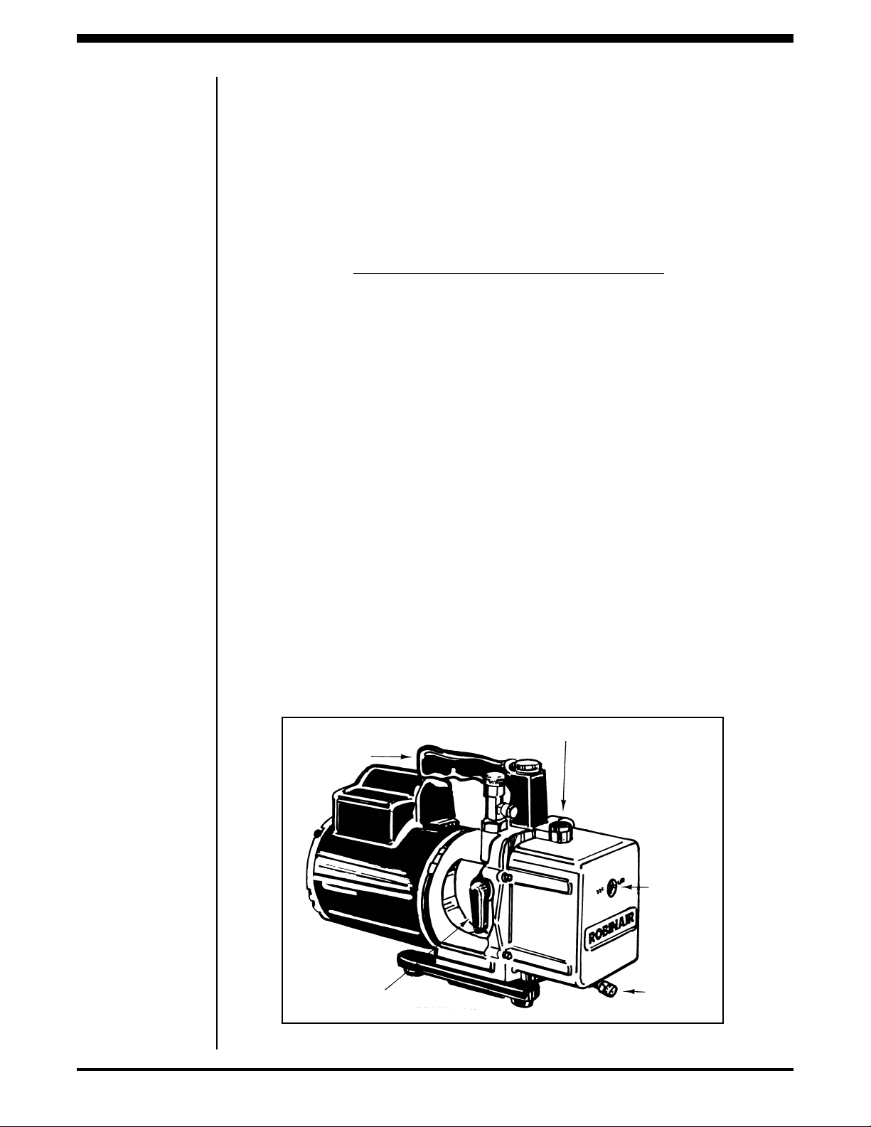
PREPARING THE VACUUM PUMP
The VacuMaster® vacuum pump is
shipped without oil in the reservoir.
Before starting the station, you must
fill the pump with oil and remove the
exhaust plug from the end of the
pump’s handle.
Note: The Iso-ValveTM isolation valve on
the side of the pump must remain open
(the position shown in the illustration)
for the station to operate.
CAUTION! Do not attempt to run the
vacuum pump when the manifold gauge
set shows pressure readings above 5 psi.
In the vacuum mode, positive pressure
will:
• High pressure — not allow the
vacuum solenoids to open.
• Low pressure — blow oil out of the
pump handle when the vacuum
solenoids do open.
Running the vacuum pump with positive
pressure locks high pressure between the
two solenoids and prevents operation of
the pump.
Follow these procedures to prepare the
vacuum pump for use with the charging
station.
1. Remove and discard the exhaust plug
from the end of the pump’s handle.
2. Remove and retain the black plug on
the oil fill port.
3. Pour vacuum pump oil into the oil fill
port until oil appears in the sight
glass on the reservoir. The approximate oil capacity of the pump is 13
ounces (384 milliliters).
4. Close both the high side and low side
valves on the station’s manifold.
2
EXHAUST PLUG
ISO-VALVEˇ
OIL FILL PORT
SIGHT
GLASS
OIL
DRAIN
VALVE
Diagram of Vacuum Pump Components
© 1991 Robinair Division, SPX Corporation
Page 5
5. Plug the station into the proper
voltage outlet, and turn on the MAIN
POWER switch.
6. Simultaneously press the ENTER
and zero keys on the keypad to access
the manual diagnostic mode.
7. Press “1” on the keypad to start the
pump.
8. While the pump is running, add
enough vacuum pump oil so that the
oil level is even with the line on the
reservoir’s sight glass.
9. Press “1” or the RESET CYCLE key
on the keypad to stop the pump.
10. Replace the black plug on the oil fill
port.
IMPORTANT! For maximum performance, change the vacuum pump oil
frequently (approximately after every
four hours of running time). We recommend using our Premium High Vacuum
Pump Oil; it is specifically blended to
maintain maximum viscosity at normal
running temperatures and to improve
cold weather starts (see the “Replacement Parts List”).
Read and follow the detailed instructions
in the Vacu-Master
®
Vacuum Pump
Operating Manual. You do not need to
return the warranty registration card
contained in the Vacu-Master® Vacuum
Pump Operating Manual — return only
the warranty registration card attached
to the station to validate your warranty.
INSTALLING A REFRIGERANT TANK
Follow these steps to install a refrigerant
tank on the charging station.
▲ WARNING ▲
! !
Always wear safety goggles when
working with refrigerants. Read and
follow all warnings at the beginning of
this manual before operating the unit.
Connecting hoses to the wrong ports
may cause personal injury or may
damage the equipment. Read and follow
all warnings at the beginning of this
manual before operating the unit.
Use only with refrigerant type R-134a!
Cross-contamination with other refrigerant types will cause severe damage to the
station and to tools and equipment.
Do not mix refrigerant types through a
system or in the same container!
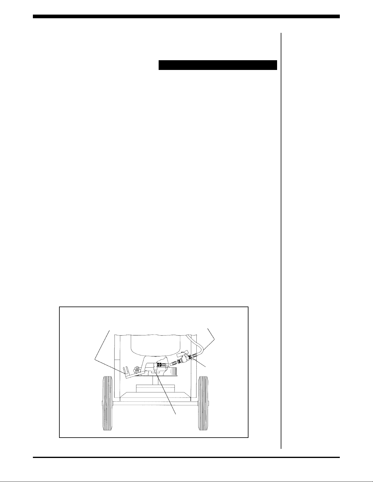
1. Attach the station’s yellow charging
hose to a full refrigerant tank, as
follows:
•Disposable tanks — Connect the
yellow hose, open the tank’s valve,
and place the inverted tank (with its
valve down) on the scale platform.
Be sure to center the tank over the
stud welding point. Use only tanks
designed for use with R-134a, including Acme threads on the fittings.
(Continued)
Set Up
Instructions
Dual Purpose
Hold-Down
Bracket
Bulk Refrigerant Tank
Diagram of Disposable Tank Installation
R-134a Smart Cart® Automatic A/C Charging Station
(Not Included)
Valve Handle
Yellow Hose To
Refrigerant
Solenoid
Valve
Tank
Ball
3
Page 6

Set Up
Instructions
•Refillable tanks — Leave the tank
upright, attach the yellow charging
hose to the blue LIQUID valve on the
tank, and open the blue valve.
2. Open the ball valve on the yellow
charging hose (the open position runs
parallel to the hose).
Note: Use a maximum tank size of 50
pounds (23 kilograms) with this charging
station.
3. Fasten the tank securely with the
tank hold-down bracket. Place the
heater blanket around the center of
the tank, and fasten it securely (see
“Using the Heater Blanket”).
4. Secure the retaining strap around
the tank.
Note: Adjust the strap so that it comes in
contact with the tank, but is not tight
around the tank .
5. If the tank was changed after pressing the HOLD key to interrupt the
cycle, press the CONT key or RESET
CYCLE key, depending on the
operation you require next.
REMOVING AN EMPTY TANK
Follow these steps to remove an empty
refrigerant tank from the charging
station.
1. If the station is operating, press the
HOLD key. You do not need to turn
off the MAIN POWER switch.
▲ WARNING ▲
! !
Disconnect hoses with extreme caution!
All hoses may contain liquid refrigerant
under pressure. Read and follow all
warnings at the beginning of this manual
before operating the unit.
2. Disconnect the hose from the tank.
3. Release the retaining strap buckle.
4. Loosen the wing nut on the holddown bracket and remove the empty
tank from the platform.
USING THE HEATER BLANKET
A heater blanket speeds the transfer of
refrigerant and assures a complete
charge by raising the pressure within the
refrigerant tank.
1. Wrap the heater blanket around the
refrigerant tank, secure it with the
®
Velcro
strap, and plug its power cord
into the heater outlet on the bottom
of the control box (right receptacle).
2. Turn on the MAIN POWER switch
on the front of the station.
The heater blanket is on whenever the
station’s MAIN POWER switch is on,
eliminating the need for manual control.
You can extend the life of the heater
blanket by unplugging the heater when
it’s not being used or turning off the
MAIN POWER switch.
4
Blue LIQUID Valve
Ball Valve
Yellow
Hose To
Refrigerant
Solenoid
Bulk
Refrigerant
Tank
(Not Included)
Platform
Mount
Diagram of Refillable Tank Installation
© 1991 Robinair Division, SPX Corporation
Ring
Page 7

Before operating the 220V 50Hz model,
plug the short power cord from the upper
control box into the outlet on the lower
power box. Plug the main power cord
into a 220V 50Hz power source that is
free from transients and electrical noise.
The chart below summarizes the steps in
each of the following sections.
TO ATTACH HOSES TO THE SYSTEM
1. Be sure all valves on the manifold are
closed.
▲ WARNING ▲
Connecting hoses to the wrong ports
may cause personal injury or may
damage the equipment. Check your A/C
system operating manual for the correct
hook-up.
Use only with refrigerant type R-134a!
Cross-contamination with other refrigerant types will cause severe damage to the
station and to tools and equipment.
Do not mix refrigerant types through a
system or in the same container!
! !
TO DIAGNOSE SYSTEM PROBLEMS
1. Start the A/C system and watch the
gauge pressures (refer to the
manufacturer’s specifications for
proper operating pressures).
2. Perform any other visual and diagnostic inspections recommended by
the manufacturer.
3. If the A/C system is operating properly, disconnect the hose couplers
from the A/C system. To recharge or
make necessary repairs, see the
appropriate sections that follow.
TO ADD REFRIGERANT TO PARTIALLY
CHARGED SYSTEMS
1. In the program mode, press ADD .2
lbs. REFRIG. The messages “AUTOMATIC” and “REFRIGERANT”
appear on the display.
2. Open the low side valve. The station
dispenses .2 pounds (.1 kilograms) of
refrigerant, then displays the message “CPL.” Close the low side valve.
Operating
Procedures
2. Attach the red high side hose’s
coupler to the high side of the A/C
system.
3. Attach the blue low side hose’s
coupler to the low side of the A/C
system.
Note: The manifold is ported so that the
gauges indicate pressure whether or not
the valves are open.
SUMMARY
1. Attach hoses to the A/C system.
2. Start the A/C system and compare operating pressures to
manufacturer’s specifications.
3. Add a partial charge, if necessary.
4. Discharge the A/C system, if required.
3. Monitor the A/C system operating
pressures. Correct any low charge
indications by pressing RESET
CYCLE; repeat Step 1 as necessary.
Note: There are other A/C system problems which cause symptoms similar to a
low refrigerant charge — refer to your
operator’s manual or a reliable A/C
troubleshooting chart. If adding one
pound of refrigerant does not correct the
low charge symptoms, you may need to
recover and/or recharge refrigerant, as
described next.
5. Program the vacuum/recharge cycles.
6. Start the A/C system and perform final operating check.
7. Disconnect the hoses from the A/C system.
Summary Chart of Operating Procedures
R-134a Smart Cart® Automatic A/C Charging Station
5
Page 8

Operating
Procedures
TO RECOVER REFRIGERANT
IMPORTANT! Use a recovery unit. Do
not vent refrigerant to the atmosphere.
1. Be sure the A/C system is turned off,
then connect the yellow hose from
the manifold’s center port to your
recovery unit’s inlet port.
2. Open the manifold’s red high side
valve, blue low side valve, and center
valve, and start the recovery unit.
Follow the recovery unit’s instructions to recover refrigerant.
TO PROGRAM VACUUM/
CHARGING CYCLE
Vacuum is programmed in minutes and
refrigerant is programmed by weight. If
no quantity for any particular category is
required, enter zeros.
1. If the message “PROGRAM” is not
displayed, press RESET CYCLE.
2. The message “VACUUM” should
appear on the display. If it does not,
press the REVIEW PROGRAM key
repeatedly until it does.
Note: Follow the A/C system manufacturer’s recommendations for the proper
vacuum and refrigerant requirements.
3. Press the appropriate number keys
until the desired vacuum time
appears on the display. Enter
vacuum time in whole minutes.
Note: Use the convenient conversion
chart on the back cover of this manual if
you need help converting ounces to
hundredths of a pound.
TO USE AUTOMATIC VACUUM/
CHARGING CYCLE
IMPORTANT! Before starting the
vacuum pump, be sure that all A/C
system pressure is discharged.
1. Close the SYSTEM DISCHARGE
valve, and open the appropriate high
side and/or low side valves on the
station.
2. Press the START key on the keypad.
The display shows the message
“AUTOMATIC” followed by the
message “VACUUM.”
3. After a slight delay the vacuum
pump starts. The display shows the
amount of time programmed and
begins a countdown to zero.
4. At the end of the automatic vacuum
cycle, the display shows the message
“HOLD.” Close the high and low side
valves and make sure the A/C system
holds a vacuum (if it doesn’t, perform
any necessary repairs). Then open
the high and low side valves, and
press CONT to continue charging.
Note: Consult your A/C system service
guide for the proper charging
procedure.
6
For example, to program 20 minutes,
press two and zero — the display
shows “20.00.” Press ENTER and the
display flashes once indicating the
programmed data is accepted.
4. Press the REVIEW PROGRAM key.
The message “REFRIGERANT”
appears on the display. Enter the
amount of refrigerant to be recharged
to hundredths of a pound.
For example, to program 2
press two, seven, five and ENTER.
The display shows “2.75” and flashes
once, indicating the programmed
data is accepted. To program 21/
pounds, press two, five, zero and
ENTER — be sure to add the last
zero.
3
/4 pounds,
2
5. During the charging cycle, the
message “REFRIGERANT” appears
on the display. The display shows the
programmed amount of refrigerant,
counts down to zero as the charging
process proceeds, and indicates the
end of the charging process by
showing the message “CPL.”
6. If the refrigerant transfer is too slow,
the station emits an audible signal,
the display countdown stops, and the
message “CHECK REFRIGERANT”
appears on the display. Press the
HOLD key and close the high side
valve, but leave the low side valve
open. Start the A/C system, and press
the CONT key to pull the remainder
of the charge into the low side of the
A/C system.
© 1991 Robinair Division, SPX Corporation
Page 9

If the signal continues and the
display does not count down, press
the HOLD key and replace the tank
as described in “Installing a Refrigerant Tank.” Press the CONT key to
complete the automatic cycle, or
press RESET to access the program
mode.
2. Compare the gauge pressure readings to the system manufacturer’s
specifications.
3. Check the cool air vent discharge
temperature to be sure that the
system cooling is acceptable.
TO DISCONNECT THE SYSTEM
Operating
Procedures
7. When the automatic cycle is completed, the station beeps once, and
the message “CPL” appears on the
display, followed by the “HOLD”
message. Press any key to access the
program mode.
TO CHECK FINAL SYSTEM OPERATION
Before disconnecting the A/C system
from the station, you should check that it
is operating properly.
CAUTION! Before starting the A/C
system, be sure both valves on the
station’s manifold are closed.
1. Run the A/C system until the gauge
readings stabilize.
Follow these instructions to properly
maintain your automatic A/C charging
station. Be sure to wipe up any spills
immediately and keep the station clean.
1. Turn off the A/C system.
▲ WARNING ▲
!
Disconnect hoses with extreme caution!
All hoses may contain liquid refrigerant
under pressure. Read and follow all
warnings at the beginning of this manual
before operating the unit.
2. Disconnect the blue and red hose
couplers from the A/C system.
3. Replace the caps on all fittings. Store
the hoses on the cart, and store the
couplers by connecting them to the
coupler rack.
2. For maximum efficiency and longer
pump life, change the vacuum pump
oil frequently (approximately after
every four hours of running time).
!
Maintenance
Instructions
STORING THE STATION
1. Turn off the MAIN POWER switch,
and unplug the station.
2. Store the hoses on the cart, and store
the couplers by connecting them to
the coupler rack.
3. Close all valves when the station is
not in use.
MAINTAINING THE VACUUM PUMP
1. Check the vacuum pump oil daily,
and add oil as necessary. The proper
level is at the midpoint of the sight
glass when the vacuum pump is
running and the A/C system is under
vacuum.
Note: Use only our Premium High
Vacuum Pump Oil (see “Replacement
Parts List”).
Read and follow the detailed instructions
in the vacuum pump operating manual
to change oil.
CHECKING THE SCALE ACCURACY
You should routinely check the accuracy
of the scale platform and calibrate the
scale, if necessary, to assure that the unit
charges accurately.
1. While in the PROGRAM mode,
simultaneously press the ENTER and
zero keys on the keypad to clear the
display.
2. Press the “6” key on the keypad to
display the approximate scale
platform weight.
3. Remove the tank from the scale
platform. The empty platform weight
displayed should range from + two
pounds. If it does not, contact the
factory.
R-134a Smart Cart® Automatic A/C Charging Station
7
Page 10

Maintenance
Instructions
CALIBRATING THE SCALE
You should also routinely calibrate the
scale, if necessary, to assure that the
compressor shuts off when the tank is
full. You can automatically calibrate the
scale through the keypad.
▲ WARNING ▲
Proper operation of the scale is essential to safety features built into the
station. If you have any questions about
scale accuracy, call the factory.
1. Press ENTER and the zero key on
the keypad to access the diagnostic
mode, then press 8-7-8-7. The display
will show “A1.”
! !
USING MANUAL DIAGNOSTICS
The station has internal and manual
diagnostic modes. The internal or selfdiagnostic mode checks for entries or
pressures outside of normal limits and
for certain electrical conditions. The
manual diagnostic mode allows you to
check major components for proper
operation.
The station’s safety features include a
check valve which prevents high side
pressure from entering the refrigerant
tank. Also, any operating problems
resulting in an error message on the
display prevent operation until the
problem is corrected.
Note: If you press any other key before
the 8-7-8-7 sequence, you cannot enter
the automatic calibration routine.
2. Be sure the scale is empty of all
weight (e.g. tank). Press “0” and then
press ENTER on the keypad. The
display shows “0.00” and then
changes to the message “A2.”
3. Place a known weight (between 10
and 80 pounds) in the center of the
scale platform. Enter that weight on
the display using the keypad, then
press ENTER. The display returns to
the VACUUM mode.
4. To re-enter the diagnostics mode and
verify the calibration, simultaneously
press ENTER and the zero key on the
keypad. Then press “6.” The display
shows the known weight on the scale
platform.
5. Remove the known weight, and the
display returns to “0.00.”
▲ WARNING ▲
Be sure to discharge any system pressure before performing any manual
diagnostics.
1. If the message “PROGRAM” is not
displayed, press the RESET CYCLE
key.
2. Simultaneously press the ENTER
and zero keys. The display should be
blank except for the decimal point.
3. Press the following keys to perform
these functions:
Press “1” — The VACUUM display
segment comes on, the vacuum
solenoid opens, and the pump starts.
Press “1” again to turn off.
Press “3” — The REFRIGERANT
display segment comes on and the
solenoid opens. This is a momentary
contact switch which turns off when
released. Close the high and low side
valves to perform this test.
! !
8
Press “5” — All display segments
light up. Press “5” again to turn off.
Press “6” — The display shows the
approximate weight on the scale. See
“Checking the Scale Accuracy” for
diagnostic procedures.
4. Press the RESET CYCLE key to
return to the program mode.
© 1991 Robinair Division, SPX Corporation
Page 11

HOW TO USE THE CONTROLS
The charging station has various components that control its operating functions.
CAUTION! Do not operate the station
until you have filled the vacuum pump
with oil and removed the exhaust plug
from the pump’s handle, as outlined in
“Preparing the Vacuum Pump.”
1. SYSTEM DISCHARGE Valve — Lets
you depressurize the A/C system.
Connect to a refrigerant recovery
unit — do not vent refrigerant to the
atmosphere.
2. LOW Side Valve — When closed,
isolates the low side of the A/C
system from the station controls.
Note: The manifold is ported so that the
gauges indicate pressure whether or not
the valves are open.
3. LOW Side Compound Gauge — When
connected to the low side of an A/C
system, indicates the system’s low
side pressure.
9. ACCESSORY Outlet — Provides an
electrical outlet for accessory equipment, such as a thermistor vacuum
gauge. This outlet is energized when
the station is plugged in, and it is
located on the side of the control box.
Note: There is no accessory outlet on the
220V 50Hz model.
10.HEATER Outlet — Provides an
electrical outlet for the refrigerant
tank’s heater blanket. This outlet is
controlled by the MAIN POWER
switch and is energized when the
power is on.
11.PUMP Outlet — Provides an electri-
cal outlet for the vacuum pump. This
outlet is controlled by the logic board.
Additional
Operating
Guidelines
4. HIGH Side Valve — When closed,
isolates the high side of the A/C
system from the station controls.
5. HIGH Side Pressure Gauge — When
connected to the high side of an A/C
system, indicates the system’s high
side pressure.
6. Display — Shows the time programmed for vacuum, the weight of
refrigerant programmed for charging, the control status, and the cycle
of operation. Detailed instructions for
programming the display follow the
next section.
7. Keypad — Accomplishes specific
operating functions, as described in
the next section.
8. MAIN POWER Switch — Supplies
electrical power to the control panel.
Diagram of Control Components
R-134a Smart Cart® Automatic A/C Charging Station
9
Page 12

Additional
Operating
Guidelines
USING THE KEYPAD
The charging station also has a unique
keypad for data entry. It uses only six
keys for sequence control, and the LCD
display indicates the operating mode.
CAUTION! Do not operate the station
until you have filled the vacuum pump
with oil and removed the exhaust plug
from the pump’s handle, as outlined in
“Preparing the Vacuum Pump.”
START — Press to begin the automatic
cycle after the charging station is programmed.
CONT — Press to resume (or continue)
operations after pressing the HOLD key
(described below).
HOLD — Press to interrupt the
automatic cycle.
REVIEW PROGRAM — Press to review
the existing programmed data.
ENTER — Press to enter program data
into the computer’s memory.
RESET CYCLE — Press to access
program mode.
USING THE DISPLAY PANEL
The charging station also displays
various messages on the display panel.
CAUTION! Do not operate the station
until you have filled the vacuum pump
with oil and removed the exhaust plug
from the pump’s handle, as outlined in
“Preparing the Vacuum Pump.”
Segment A — Indicates in which mode
the station is operating:
PROGRAM — The station is in the
programming mode, which allows
you to program vacuum time and
refrigerant weight or to review the
existing program.
HOLD — The evacuation process is
complete and the vacuum pump is
off, or no refrigerant is being
charged; also HOLD is used while
changing a refrigerant tank or to
interrupt the vacuum/charging
cycles.
AUTOMATIC — Either the vacuum
or refrigerant charging cycle is in
process.
ADD .2 LB. REFRIG. — Press to partially
charge the A/C system.
Diagram of Keypad
Segment B — Indicates the station is
either evacuating the A/C system or
charging refrigerant or the station is
ready to be programmed for one of these
two functions:
VACUUM
• With PROGRAM, indicates the
station is ready to be programmed for
evacuation.
• With AUTOMATIC, indicates the
vacuum pump is running; the number displayed counts down in seconds, showing the amount of time
remaining for evacuation.
• With HOLD, indicates the vacuum
cycle is complete (if the display shows
“0.00”), or if you pressed the HOLD
key to interrupt the vacuum cycle,
indicates the remaining time the
pump runs when you press the
CONT key.
10
© 1991 Robinair Division, SPX Corporation
Page 13

Segment B Messages
Additional
VACUUM + PROGRAM = Program station for vacuum
VACUUM + AUTOMATIC = Vacuum pump is running
VACUUM + HOLD = Evacuation complete or
interrupted vacuum cycle
REFRIGERANT + PROGRAM = Program station for charge
REFRIGERANT + AUTOMATIC = Station is charging A/C system
REFRIGERANT + HOLD = Interrupted charging cycle
Quick Reference Chart
REFRIGERANT (POUNDS)
• With PROGRAM, indicates the
station is ready to be programmed
for the amount of refrigerant to be
charged into the A/C system;
on the keypad enter the charge in
pounds (or kilograms, depending on
the model you have).
• With AUTOMATIC, indicates the
station is charging refrigerant into
the A/C system; the number shown
on the display counts down, showing
the remaining amount of refrigerant
to be dispensed.
• With HOLD, indicates the HOLD key
was pressed to interrupt the charging
cycle; the number shown on the
display is the amount of refrigerant
remaining to be charged into the
system. To continue charging, press
CONT.
Use the quick reference chart above to
interpret Segment B messages.
Segment C — Shows a number or a
coded error message on the display that
indicates the station’s operating status or
any specific problems.
NUMBER
Indicates the vacuum time in minutes or the refrigerant weight in
pounds (or kilograms, depending on
the model you have).
MESSAGE CODES
• CPL — Indicates the refrigerant
charging cycle is complete.
• ERR5 — Indicates an overloaded or
broken scale.
Segment D — Indicates the transfer of
refrigerant is slow or has stopped.
•If the disposable tank is empty or
the refillable tank is low , replace
the tank following the instructions in
“Installing a Refrigerant Tank.” A
small amount of refrigerant always
remains in a refillable tank.
•If there is adequate refrigerant in
the tank , you need to pull the
remainder of the programmed charge
into the low side of the A/C system,
as outlined in Step 7 of “To Use
Automatic Vacuum/Charging Cycles.”
Operating
Guidelines
Diagram of Display Panel
R-134a Smart Cart® Automatic A/C Charging Station
11
Page 14

Replacement
Parts List
The following is a list of replacement
parts you may need to service or maintain your automatic charging station.
Because of ongoing product improvements, we
reserve the right to change design, specifications,
or materials without notice.
Description 115V 60 Hz 220V 50 Hz
Handle (Red) 40448 40448
Handle (Blue) 40447 40447
Gauge, Blue Low Side Compound 11741 11726
Gauge, Red High Side Pressure 11742 11727
High Side Coupler 18191 18191
Low Side Coupler 18190 18190
Vacuum Pump RA15427 RA15428
120” Blue Hose 62120 62120
120” Red Hose 63120 63120
60” Yellow Hose 37160 37160
9” Blue Hose 37059 37059
Tank Hose 37024 37024
Black Vacuum Hose 40586 40586
Main Power Switch RA40994 RA40994
Scale Assembly RA19008 RA19008
Tank Platform RA14967 RA14967
Heater Blanket 10994 45605
Vacuum Solenoid Assembly RA19020 RA19020
Refrigerant Solenoid RA19006 RA19006
Main Board RA18761 RA19092
Keypad RA18751 RA18751
Check Valve RA17112 RA17112
Tank Strap RA19056 RA19056
Cover 17495 17495
Wheel & Nut RA10751 RA10751
Transformer N/A RA19091
High Vacuum Grease 13033 13033
Our Premium High Vacuum Pump Oil is
also available in handy quart containers
or in convenient gallon containers:
Quart (shipped 12 quarts per case) 13203
Gallon (shipped 4 gallons per case) 13204
This oil has been specifically blended to
maintain maximum viscosity and to
improve cold weather starts.
12
© 1991 Robinair Division, SPX Corporation
Page 15

Symptom Cause Cure
Trouble-
No power when
POWER switch is on —
no display showing
Vacuum pump does not
start
Audible tone sounds
and “CHECK REFRIGERANT” message
displays during
refrigerant transfer
Refrigerant doesn’t flow
or “REFRIGERANT”
message doesn’t
display
• Station unplugged • Plug station into power
source
• No power at wall outlet • Locate problem with outlet or
change outlets
• Vacuum pump unplugged • Plug pump into power source
• Vacuum time not entered • Program required vacuum
time
• Defective vacuum pump • Remove and replace pump
• Faulty components • Call factory
• Transfer stopped or • Start A/C system and pull
too slow rest of refrigerant into system
(Step 6 in “To Use Automatic
Vacuum/Charge Cycle”)
• Tank safety strap too tight • Loosen the safety strap
• Refrigerant supply empty • Replace the refrigerant tank
or call factory
• Refrigerant supply empty • Replace the refrigerant tank
Shooting
Tips
Vacuum pump runs, but
low side gauge does not
register an appropriate
vacuum
ERR5
• Discharge valve open • Close discharge valve
• Low side valve closed • Open low side valve
• Pump oil contaminated • Flush and change pump oil
• Hose gasket damaged • Replace gasket or hose
• Charging line loose • Check connections
• Manifold leaking • Check connections
• Pump’s Iso-valve closed • Open Iso-valve
• Overloaded or broken • Check tank weight, recali-
scale brate if necessary, or call
factory
R-134a Smart Cart® Automatic A/C Charging Station
13
Page 16

Temperature — Pressure Relation
R-134a Refrigerant
Conversion Chart
Ounces to Hundredths of a Pound
PSI
(oF) R-34a
-20 -1.8
-15 0
-10 2.0
-5 4.1
0 6.5
5 9.1
10 12.0
15 15.1
20 18.4
25 22.1
30 26.1
35 30.4
40 35.0
45 40.1
50 45.4
55 51.3
60 57.4
65 64.0
70 71.1
75 78.5
80 86.7
85 95.3
90 104.3
95 113.9
100 124.1
105 134.9
110 146.3
115 158.4
120 171.1
125 184.5
130 198.7
135 213.5
140 229.2
Note
: Gauge pressures are approximations
rounded to the nearest 1/20 PSI.
Ounce Pound
1 .06
2 .12
3 .19
4 .25
5 .31
6 .38
7 .44
8 .50
9 .56
10 .62
11 .69
12 .75
13 .81
14 .88
15 .94
16 1.00
☎
For assistance in servicing or using the
Automatic A/C Charging Station, call the
toll-free Service Line, 800-822-5561, inside
the continental U.S. In Canada, call 419485-5561, Ext. 300. In all other locations,
contact your local distributor. To help us
serve you better, please be prepared to
provide the model number, serial number,
and date of purchase.
To validate your warranty, you must complete the warranty card attached to your
station and return it within ten days from
date of purchase.
x
SP
ROBINAIR
Robinair Division
SPX Corporation
Robinair Way
Montpelier, OH 43543-0193 USA
Phone 419-485-5561
FAX 419-485-8300
© 1993 Robinair Division, SPX Corporation34100/10324 Smart Cart Charging Station
Printed In USA111615 (Rev. 1/94)
 Loading...