

Page 1
O
p
e
r
a
t
i
n
g
M
a
n
u
a
l
Operating Manual
Manual de funcionamiento
Manuel d’utilisation
Not for use in automotive
R-134a applications.
Model 25200B
Refrigerant Recovery Unit
Page 2
Model 25200B
Refrigerant Recovery Unit
Design Pressure: 336 psig — 435 psig
SAFETY DEFINITIONS: Follow all WARNING, CAUTION, IMPORTANT, and NOTE messages in this manual. These messages are
dened as follows: WARNING means you may risk serious personal injury or death; CAUTION means you may risk personal injury,
property damage, or unit damage; IMPORTANT means you may risk unit damage; and NOTEs and
ity and helpful information. These safety messages cover situations ROBINAIR is aware of. ROBINAIR cannot know, evaluate, and
advise you as to all possible hazards. You must verify that conditions and procedures do not jeopardize your personal safety.
DISCLAIMER: Information, illustrations, and specications contained in this manual are based on the latest information available
at the time of publication. The right is reserved to make changes at any time without obligation to notify any person or organization
of such revisions or changes. Further, ROBINAIR shall not be liable for errors contained herein or for incidental or consequential
damages (including lost prots) in connection with the furnishing, performance, or use of this material. If necessary, obtain additional
health and safety information from the appropriate government agencies and the vehicle, refrigerant, and lubricant manufacturers.
OPERATING TIPS provide clar-
WARNINGS
ALLOW ONLY QUALIFIED PERSONNEL TO OPERATE THE UNIT. Before operating the unit, read and follow
the instructions and warnings in this manual. The operator must be familiar with air conditioning and refrigeration
systems, refrigerants, and the dangers of pressurized components. If the operator cannot read this manual,
operating instructions and safety precautions must be read and discussed in the operator’s native language.
PRESSURIZED TANK CONTAINS LIQUID REFRIGERANT. Do not overll the internal storage vessel, because
overlling may cause explosion and personal injury or death. Do not recover refrigerants into nonrellable
containers; use only federally authorized rellable containers (DOT spec. 4BW or 4BA).
HOSES MAY CONTAIN LIQUID REFRIGERANT UNDER PRESSURE. Contact with refrigerant may cause per-
sonal injury. Wear protective equipment, including safety goggles. Disconnect hoses using extreme caution.
DO NOT BREATHE REFRIGERANT AND LUBRICANT VAPOR OR MIST. Exposure may cause personal
injury, especially to the eyes, nose, throat, and lungs. Use the unit in locations with mechanical ventilation that
provides at least four air changes per hour, or position the unit 18 inches above the oor. If accidental system
discharge occurs, ventilate the work area before resuming service.
DO NOT USE AN EXTENSION CORD. An extension cord may overheat and cause re. If you must use an
extension cord, use the shortest possible cord with a minimum size of 14 A
T
O REDUCE THE RISK OF FIRE, do not use the unit in the vicinity of spilled or open containers of gasoline
or other ammable substances.
DO NOT USE COMPRESSED AIR TO PRESSURE TEST OR LEAK TEST THE UNIT OR HVAC/R SYSTEM.
Some mixtures of air and refrigerant are combustible at elevated pressures. These mixtures are potentially
dangerous and may result in re or explosion causing personal injury or property damage.
USE THIS UNIT WITH ONLY THE FOLLOWING REFRIGERANTS: R-12, R-22, R-134a, R-401A, R-401B,
R-402A, R-402B, R-404A, R-407A, R-407B, R-407C, R-408A, R-409A, R-410A, R-500, R-502, R-507. The
unit is designed to only recover refrigerant. Do not attempt to adapt the unit for refrigerant that is not in this
list. Do not mix refrigerant types through a system or in the same container; mixing of refrigerants will cause
severe damage to the unit and the air conditioning system.
HIGH VOLTAGE ELECTRICITY INSIDE THE UNIT HAS A RISK OF ELECTRICAL SHOCK. Exposure may
cause personal injury. Disconnect the power before servicing the unit.
ADDITIONAL HEALTH AND SAFETY INFORMATION MAY BE OBTAINED FROM THE REFRIGERANT
AND LUBRICANT MANUFACTURERS.
WG.
This equipment has been certied by ARI to meet the EPA minimum requirements for recovery equipment
intended for use with all HCFC applicances and other high pressure applicances.
OPERATING NOTE: At temperatures exceeding 120° F / 49° C, wait 10 minutes between recovery jobs.
Page 3

TABLE OF CONTENTS
Glossary of Terms . . . . . . . . . . . . . . . . . . . . . . . . . . . 1
Operating Guidelines . . . . . . . . . . . . . . . . . . . . . . . . . 2
Setup Instructions . . . . . . . . . . . . . . . . . . . . . . . . . . 2
Operating Instructions . . . . . . . . . . . . . . . . . . . . . . . . 4
Recovery Procedure . . . . . . . . . . . . . . . . . . . . . . . . 4
Tank-to-Tank Transfer . . . . . . . . . . . . . . . . . . . . . . 5
High Pressure . . . . . . . . . . . . . . . . . . . . . . . . . . . 5
Self-Clearing Procedure . . . . . . . . . . . . . . . . . . . . . . 6
Maintenance. . . . . . . . . . . . . . . . . . . . . . . . . . . . . . 7
Replacement Parts . . . . . . . . . . . . . . . . . . . . . . . . 7
Introduction
Troubleshooting Tips . . . . . . . . . . . . . . . . . . . . . . . . . 8
Flow Diagram . . . . . . . . . . . . . . . . . . . . . . . . . . . . . 9
Wiring Diagram . . . . . . . . . . . . . . . . . . . . . . . . . . . 10
Conversion Chart . . . . . . . . . . . . . . . . . . . . . . . . . . 11
Warranty Statement . . . . . . . . . . . . . . . . . . . . . . . . 12
Safety Precautions . . . . . . . . . . . . . . . . . inside front cover
GLOSSARY OF TERMS
A/C-R Air conditioning or refrigeration.
A/C-R System The air conditioning or refrigeration system being serviced.
Unit The refrigerant recovery unit.
Tank Therellablerefrigeranttank.
552701 Rev. A April 7, 2009
1
Page 4
Setup Instructions
OPERATING GUIDELINES
• The voltage at the unit must be ±10% of the unit’s rated voltage.
• Extension cords must be a minimum of 14 AWG and kept as short as possible.
• To minimize mixing of refrigerants, the self-clearing procedure must be
performed after each recovery operation.
• The low-side gauge on the unit allows you to monitor system pressure and stop
recovery when a deep enough vacuum has been reached. The high-side gauge
allows you to monitor the rellable tank pressure.
• When changing from liquid to vapor, the unit may switch back and forth several
times before staying on vapor. You may notice the liquid light switching and
hear the solenoids opening and closing. This is normal and does not affect the
unit or its operation.
SET-UP INSTRUCTIONS
The unit comes with four 60-inch Enviro-Guard hoses with ball valves. Either
blue hose may be used where blue hose connections are called for, and either red
hose may be used for red hose connections.
CAUTION: To prevent personal injury, all valves on hoses must be in
the closed position before making connections.
1. Connect the hoses as follows:
Hose Connect Standard End To: Connect Ball Valve End To:
Blue Hose TANK LIQUID tting on unit LIQUID port on tank
Red Hose TANK VAPOR tting on unit VAPOR port on tank
Blue Hose SYSTEM VAPOR tting on unit SYSTEM VAPOR port
Red Hose SYSTEM LIQUID tting on unit SYSTEM LIQUID port
2. Plug the unit into a correct voltage electrical outlet. The fan starts running
immediately and the unit is ready for operation.
2
Page 5
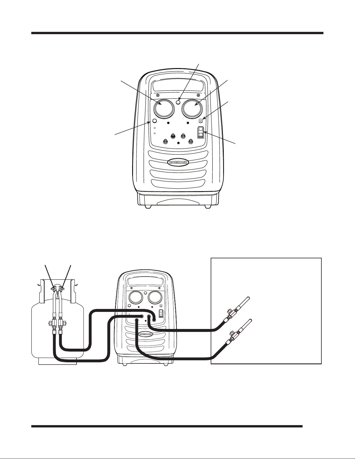
Setup Instructions
Liquid
Valve
Vapor
Valve
TYPICAL
A/C-R SYSTEM
Vapor
Liquid
TANK LIQUID
TANK VAPOR
SYSTEM VAPOR
SYSTEM LIQUID
Liquid Indicator
System Pressure
High Pressure Indicator
Tank Pressure
Circuit Breaker
Recover / Power / Clear
Switch
Front View of Unit
552701 Rev. A April 7, 2009
Hose Connections
3
Page 6

Operating Instructions
RECOVERY PROCEDURE
To prevent personal injury,
Read and follow all warnings at the beginning of this manual
before operating the unit. Wear safety goggles when working with
refrigerants. Use only authorized rellable refrigerant tanks.
Disconnect hoses using extreme caution. All hoses may contain
refrigerant under pressure.
1. Connect hoses as described in the Setup Instructions.
2. Open the LIQUID and VAPOR valves on the recovery tank. Open the ball
valves on all four hoses.
NOTE: To prevent overlling, monitor the tank capacity/weight during recovery.
During liquid recovery, refrigerant transfers rapidly. Monitor tank weight using the
appropriate weight scale.
WARNING
3. Look at the system pressure gauge on the unit to conrm there is refrigerant
pressure in the system. If there is no pressure, there is no refrigerant to be
recovered.
NOTE: By taking the ambient temperature and using a pressure/temperature chart,
you can use this pressure to determine the type of refrigerant in the system.
4. Turn the switch to RECOVER. The light on the switch illuminates and you
will hear the compressor start.
A oat chamber monitors the refrigerant being recovered and automatically adjusts
the unit to handle either liquid or vapor refrigerant. This provides for the most
efcient recovery. The amber light on the control panel indicates when liquid is
entering the unit.
5. The blue gauge labeled SYSTEM PRESSURE shows the current system
pressure throughout the recovery process. When the system pressure reaches
an adequate vacuum level, turn the RECOVERY switch OFF.
The recovery process is complete, but the unit must be cleared before disconnecting
all hoses. (Refer to the Self-Clearing Procedure.)
TANK CAPACITY CHART
Refrigerants 30 lb. Tank 50 lb. Tank
R-12 22 lbs. 40 lbs.
R-22 22 lbs. 40 lbs.
R-134a 22 lbs. 41 lbs.
R-407C 21 lbs. 39 lbs.
R-410A 19 lbs. 36 lbs.
4
Page 7

Operating Instructions
WARNING
The refrigerant level in the tank must not exceed 80% of the tank
volume. Failure to monitor the level could result in excessive
hydrostatic pressures, causing physical injury or death.
TANK-TO-TANK TRANSFER
When recovering refrigerant from one rellable tank into another, the color of the
hoses used for SYSTEM LIQUID and SYSTEM VAPOR may not match the color
of the liquid and vapor valves on the tank you are pulling the refrigerant from.
Conrm the hose for SYSTEM LIQUID is connected to the liquid valve of the tank,
and the hose for SYSTEM VAPOR is connected to the vapor valve of the tank.
1. Connect the hoses in the following manner.
Standard End connects to: Ball Valve End connects to:
TANK LIQUID tting on unit LIQUID port on tank refrigerant
is being transferred into
TANK VAPOR tting on unit VAPOR port on tank refrigerant
is being transferred into
SYSTEM VAPOR tting on unit VAPOR port on tank refrigerant
is being transferred from
SYSTEM LIQUID tting on unit LIQUID port on tank refrigerant
is being transferred from
2. Follow Steps 1 through 5 in the Recovery Procedure on the previous page.
NOTE: Remember to monitor tank weight.
HIGH PRESSURE
If, during the recovery or self-clearing process, the HIGH PRESSURE light comes
on, verify all appropriate valves are open. If the valves are open and the light is
still on, there is an excessive amount of air or the tank is full. Follow these steps:
1. Press the COMPRESSOR switch to OFF.
2. Close both valves on the rellable tank, and close both valves on the red and
blue hoses connected to the tank.
3. Disconnect the red hose and the blue hose from the rellable tank.
4. Replace this tank with an empty rellable tank.
5. Reconnect the hoses as described in the Setup Instructions. Then follow the
steps in either the Recovery Procedure or the Self-Clearing Procedure.
If, after completing the above steps, either light is still on, call the Technical
Support Line at (800) 822-5561.
552701 Rev. A April 7, 2009
5
Page 8

Operating Instructions
SELF-CLEARING PROCEDURE
CAUTION! Do not mix refrigerant types. Always perform the selfclearing procedure after each recovery. Beginning each job with a
“clean” unit will help eliminate mixing of different refrigerant types.
1. Close the ball valves on the red and blue hoses connected to the A/C-R
system. Disconnect these hoses from the system’s access ports.
2. Close the blue LIQUID valve on the tank and the ball valve on the blue
TANK LIQUID hose. Disconnect the TANK LIQUID hose from the tank.
3. Verify the red TANK VAPOR hose is still connected to the red VAPOR tting
on the tank. Both the tank’s red VAPOR valve and the ball valve on the red
TANK VAPOR hose should be open.
4. Press the switch to SELF-CLEAR. You will hear the compressor start and the
switch will illuminate.
5. Let the compressor run until the system pressure gauge reaches the
appropriate vacuum level. The system pressure gauge will return to
VACUUM. Press the COMPRESSOR switch to OFF. Unplug the unit from
the electrical source.
6. Close the red VAPOR valve on the tank and the ball valve on the red TANK
VAPOR hose. Disconnect the TANK VAPOR hose from the tank.
WARNING
To prevent personal injury, disconnect hoses using extreme
caution. All hoses may contain refrigerant under pressure.
7. While the hoses are still connected to the unit, slowly open the ball valve
on each hose to relieve any pressure in the hose. Close the ball valves, then
disconnect the hoses from the unit.
6
Page 9

Maintenance
This unit has been designed for minimal maintenance. The compressor should be
evaluated for wear after 2,500 hours of use. Call Robinair’s Technical Support
Line, (800) 822-5561, for the location of an authorized Robinair service center
near you.
REPLACEMENT PARTS
System Pressure Gauge 551196
Tank Pressure Gauge 551197
Switch—Compressor 19813
High Pressure Cut-Out 19720
Ball Valve Hose—60” Red 65360
Ball Valve Hose—60” Blue 65260
Compressor 19652
Indicator Light, Red 111029
Indicator Light, Amber 111030
Fan 109820
Float Chamber 19685
CAUTION!
Use only standard
soap and water
to clean the
shroud and/or
base. Industrial
solvents found in
most cleaners and
degreasers can
cause the plastic
to crystallize and
become brittle.
Relay Board 19699
Case Bottom 121840
Case Back 121839
Case Front 121838
552701 Rev. A April 7, 2009
7
Page 10

Troubleshooting Tips
Compressor does not start
Problem: Compressor circuit breaker has tripped.
Solution: Depress the circuit breaker switch.
Problem: HIGH PRESSURE light is ON.
Solution: The high side pressure switch has tripped; verify the tank and
hose ball valves are open. Check tank and verify it is not full.
Problem: COMPRESSOR switch is not ON.
Solution: Press the COMPRESSOR switch to ON.
Compressor runs but does not move refrigerant
Problem: The ball valves on the hoses are not open.
Solution: Open the ball valves.
Problem: The tank valves are not open.
Solution: Open the valves.
During recovery, unit shuts off on high pressure
Problem: The rellable tank valves are not open.
Solution: Open the tank valves.
Problem: Valves on hoses are shut.
Solution: Open valves.
Unit will not pull down to appropriate vacuum level
Problem: There is a leak in the A/C system.
Solution: Fix the leak.
8
Problem: Trapped pockets of refrigerant.
Solution: Allow system to stabilize then heat with a heat gun.
Page 11

Flow Diagram
552701 Rev. A April 7, 2009
9
Page 12

Wiring Diagram
10
Page 13

CONVERSION
TABLE
OZ. LBS.
0.5 0.03
1.0 0.06
1.5 0.09
2.0 0.13
2.5 0.16
3.0 0.19
3.5 0.22
4.0 0.25
4.5 0.28
5.0 0.31
5.5 0.34
6.0 0.38
6.5 0.41
7.0 0.44
7.5 0.47
8.0 0.50
8.5 0.53
9.0 0.56
9.5 0.59
10.0 0.63
10.5 0.66
11.0 0.69
11.5 0.72
12.0 0.75
12.5 0.78
13.0 0.81
13.5 0.84
14.0 0.88
14.5 0.91
15.0 0.94
15.5 0.97
16.0 1 lb.
Conversion Table
552701 Rev. A April 7, 2009
11
Page 14

Warranty
Robinair
Limited Warranty Statement
Rev. November 1, 2005
This product is warranted to be free from defects in workmanship, materials, and components for a period of one year from
date of purchase. All parts and labor required to repair defective products covered under the warranty will be at no charge. The
following restrictions apply:
1. The limited warranty applies to the original purchaser only.
2. The warranty applies to the product in normal usage situations only, as described in the Operating Manual. The product
must be serviced and maintained as specied.
3. If the product fails, it will be repaired or replaced at the option of the manufacturer.
4. Transportation charges for warranty service will be reimbursed by the factory upon verication of the warranty claim and
submission of a freight bill for normal ground service. Approval from the manufacturer must be obtained prior to shipping
to an authorized service center.
5. Warranty service claims are subject to authorized inspection for product defect(s).
6. The manufacturer shall not be responsible for any additional costs associated with a product failure including, but not
limited to, loss of work time, loss of refrigerant, cross-contamination of refrigerant, and unauthorized shipping and/or labor
charges.
7. All warranty service claims must be made within the specied warranty period. Proof-of-purchase date must be supplied to
the manufacturer.
8. Use of recovery/recycling equipment with unauthorized refrigerants or sealants will void warranty.
• Authorized refrigerants are listed on the equipment or are available through the Technical Service Department.
• The manufacturer prohibits the use of the recovery/recycling equipment on air conditioning (A/C) systems containing leak
sealants, either of a seal-swelling or aerobic nature.
This Limited Warranty does NOT apply if:
• The product, or product part, is broken by accident.
• The product is misused, tampered with, or modied.
• The product is used for recovering or recycling any substance other than the specied refrigerant type. This includes, but is
not limited to, materials and chemicals used to seal leaks in A/C systems.
12
Page 15

Visit our web site at www.robinair.com or call our toll-free
Technical Support Line at 800-822-5561
in the continental U.S. or Canada.
In all other locations, contact your local distributor. To help us serve you better, please be prepared to provide the model
number, serial number, and date of purchase of your unit. To validate your warranty, complete the warranty card attached
to the unit, and return it within ten days from date of purchase.
NATIONWIDE NETWORK OF AUTHORIZED SERVICE CENTERS
If your unit needs repair or replacement parts, contact the service center in your area. For help in locating a service center,
call the toll-free technical support line or visit www.robinair.com.
Visite nuestro sitio web en www.robinair.com o llame sin costo a
la línea de Asistencia técnica al 800-822-5561
en EE.UU. continental o Canadá.
En todas las demás ubicaciones, comuníquese con su distribuidor local. Para ayudarnos a servirle mejor, tenga a mano el número de
modelo, número de serie y fecha de compra de su unidad. Para validar la garantía, complete la tarjeta de garantía anexa a su unidad y
enviela dentro de los diez días siguientes a la fecha de compra.
RED NACIONAL DE CENTROS DE SERVICIO AUTORIZADOS
Si su unidad necesita reparaciones o partes de reemplazo, comuníquese con el centro de servicio de su área. Para obtener ayuda para
ubicar un centro de servicio, llame sin costo a la línea de asistencia técnica o visite www.robinair.com.
Visitez notre site Web à www.robinair.com ou appelez sans frais
le soutien technique au 800-822-5561
sur le territoire continental des États-Unis ou au Canada.
Pour tout autre endroit, contactez votre distributeur local. An de nous aider à mieux vous servir, soyez prêt à nous donner le numéro
de modèle, le numéro de série et la date d’achat de votre unité. An de valider votre garantie, remplissez la carte de garantie jointe à
votre système et renvoyez-la dans les dix jours suivant la date d’achat.
RÉSEAU NATIONAL DES CENTRES DE SERVICE AUTORISÉS
Si votre unité doit être réparée ou à besoin de pièces de remplacement, contactez le centre de service de votre région. Pour vous aider
à localiser un centre de service, appelez sans frais la ligne de soutien technique ou visitez www.robinair.com.
Due to ongoing product improvements, we reserve the right to change design, specications, and materials without notice.
En raison des améliorations constantes apportées à nos produits, nous nous réservons le droit de changer de concept, de spécications et de matériaux sans préavis.
Debido a las constantes mejoras del producto, nos reservamos el derecho de cambiar diseño, especicaciones y materiales sin aviso.
Page 16

owaton na, Mn 55060-0995 Usa
655 EisEnhowE r DrivE
TECH SE RVICES 800 822 5561
CUSTOMER SERVICE 800 533 6127
FAX 412 690 2001
FAX 800 322 2890
www.robinair.com
552701 (Rev. A, April 7, 2009) © 2009 SPX
 Loading...