

Page 1
○ ○○○○○○○○○○○○○○○○○○○○○○○○○○○○○○○○○○○○○○○○○○○○○○○○○○○○○○○○○○○○○○○○○○○○
Operating Manual
Model 176802K
Refrigerant Recovery Station
Page 2
Model: 176802K
Refrigerant Recovery
Station
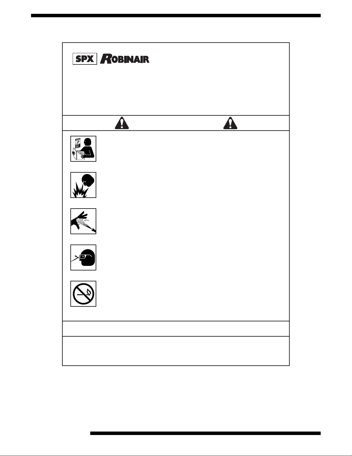
TO PREVENT PERSONAL INJURY AND/OR EQUIPMENT DAMAGE :
BEFORE OPERATING THE REFRIGERANT RECOVERY STATION, READ AND FOL-
LOW THE OPERATING INSTRUCTIONS AND SAFETY PRECAUTIONS IN THIS
MANUAL. This station should only be operated by qualified personnel. The operator must
be familiar with A/C-R systems, refrigerants, and the dangers of pressurized components.
If the operator cannot read these instructions, safety precautions and instructions must be
read and discussed in the operator's native language.
– Si el operador no puede leer inglés, las instrucciones de operación y las precauciones de
seguridad deberán leerse y comentarse en el idioma nativo del operador.
– Si l'utilisateur ne peut lire l'anglais, les instructions et les consignes de sécurité doivent lui
être expliquées dans sa langue maternelle.
THE PRESSURIZED TANK CONTAINS LIQUID REFRIGERANT. OVERFILLING THE
TANK MAY CAUSE VIOLENT EXPLOSION AND POSSIBLE INJURY OR DEA TH. Safety
devices require the use of only the following Robinair refrigerant tank: 17686 (50-lb. tank).
Do not recover refrigerants into a nonrefillable storage container! Federal regulations require refrigerant to be transported only in containers meeting DOT spec. 4BW or DOT
spec. 4BA.
ALL HOSES MA Y CONTAIN LIQUID REFRIGERANT UNDER PRESSURE. Contact with
refrigerant may cause injury. W ear protective equipment, including safety goggles. Disconnect hoses using extreme caution.
VERIFY ALL SAFETY DEVICES ARE FUNCTIONING CORRECTLY BEFORE OPERA TING THE STATION.
THIS UNIT CONTAINS MIXED REFRIGERANT WHICH CANNOT BE USED IN ANY
A/C SYSTEM. This tank may contain hydrocarbons. Do not use around open flame or
spark-generating equipment.
Refrigerant: Mixed
Serial No.:
Date Code:
WARNING
2
ATTENTION!
Ce réservoir sous pression contient du frigorigène liquids. S’il est surchargé, ce réservoir peut exploser
et causer des blessures ou la mort.
ATTENTION. Débrancher avant la maintenance.
© 2000 Robinair Division, SPX Corporation
Page 3

Introduction
TABLE OF CONTENTS
Glossary of Terms . . . . . . . . . . . . . . . . . . . . . . . . . . . . . . . . . . . . . . . . . . . 3
Introduction . . . . . . . . . . . . . . . . . . . . . . . . . . . . . . . . . . . . . . . . . . . . . . . . 3
Setup Instructions . . . . . . . . . . . . . . . . . . . . . . . . . . . . . . . . . . . . . . . . . . . 4
Diagram of Station’s Components
Diagram of Control Panel
Operating Instructions . . . . . . . . . . . . . . . . . . . . . . . . . . . . . . . . . . . . . . . . 6
Maintenance Instructions . . . . . . . . . . . . . . . . . . . . . . . . . . . . . . . . . . . . . 7
Replacement Parts List . . . . . . . . . . . . . . . . . . . . . . . . . . . . . . . . . . . . . . . 7
Troubleshooting Tips . . . . . . . . . . . . . . . . . . . . . . . . . . . . . . . . . . . . . . . . . 9
Limited Warranty . . . . . . . . . . . . . . . . . . . . . . . . . . . . . . . . . . . . . . . . . . . 11
. . . . . . . . . . . . . . . . . . . . . . . . . . . . . . . . . . 5
. . . . . . . . . . . . . . . . . . . . . . . . . . . . 5
GLOSSARY OF TERMS
A/C . . . . . . . . . Air conditioning
A/C System . . The air conditioning system being serviced
Station . . . . . . The 176802K Scavenger™ Refrigerant Recovery Station
Tank . . . . . . . . The refrigerant tank
INTRODUCTION
The Scavenger™ Refrigerant Recovery Station removes contaminated or unknown
refrigerant from automotive A/C systems to prevent the cross-contamination of a
service station’s R-12 and R-134a supply.
It is designed specifically for use with a refrigerant identifier capable of determining if the refrigerant is R-12, R-134A, or some other (unknown) refrigerant. In the
case of an unknown refrigerant, the service technician can use this station to
recover the refrigerant into a special 50-pound tank for transport to a disposal
facility.
Model 176802K Scavenger™ Recovery Unit
3
Page 4

Setup Instructions
To initially set up the station for operation:
1. Unpack all components and verify you have the following:
(1) 50-pound refrigerant tank
(1) 96" Blue Enviro-Guard® Hose for R-12
(1) 96" Blue Enviro-Guard® Hose for R-134a (with adapter)
Please read this operating manual, and fill out and return the warranty registration
card.
2. Connect the two 96" blue hoses to their respective 1/4" flare and 1/2" Acme inlet
NOTE:
The numbers in
parentheses
correspond to the
callouts shown in
the diagrams on
page 5.
ports (7) on the back of the station. (Connect the hose ends without the valves to
the station.)
The inlet ports on the back of the station are capped for shipment. Both hoses
must be connected to the station during recovery, or the unused port must be
capped. When not in use, the hoses can be wrapped around the station’s handle.
3. The station is equipped with its own regulator (6) that has an inlet with 1/4" female
pipe thread. A male air line connector (not included) that matches your air system
must be connected to the regulator.
4. The station is equipped with its own air line lubricator (4) to lubricate the air
motor that runs the compressor inside the unit. This lubricator must be filled with
3
/4 oz. (22 ml) of pneumatic air line oil or detergent SAE #10 motor oil.
Unscrew the plastic bowl on the lubricator and fill with oil to approximately 1/2"
below the top of the bowl. (Do not lose the o-ring on the top of the bowl.) Replace
the bowl on the lubricator. Snug down, but do not overtighten.
IMPORTANT: The bowls for both the lubricator and regulator are
made from polycarbonate. Oils used in the lubricator bowl must be
compatible with polycarbonate. Some “fire resistant” oil additives are
not compatible; do not expose bowls to acetone, trichloroethane,
gasoline, alcohols, ketones, esters, chlorinated hydrocarbons, or
toluene. Wash the bowls only with warm water or kerosene.
5. The tank supplied with the Scavenger™ is filled with 10 to 15 psi of dry nitrogen
which must be removed before it can be used. Open the tank valve to release the
nitrogen. Use a separate vacuum pump to pull a five-minute vacuum on the tank.
6. The tank is now ready to be connected to the recovery station. Place the tank on
the platform just over the axle on the rear of the station. Tighten the black strap
securely around the tank. Connect the black 3/8" hose (2) coming from the back of
the station to the 3/8" flare fitting on the tank’s blue (LIQUID) valve.
4
7. Connect the yellow float switch cable to the tank.
© 2000 Robinair Division, SPX Corporation
Page 5

Set Up Instructions
0
1
0
20
3
0
40
3
0
G
N
I
H
35
0
S
I
P
1
20
ROBINAIR
11
0
100
90
5
0
60
7
0
80
0
P
S
I
500
ROBINAIR
5
0
100
15
0
2
00
250
3
5
0
45
0
400
3
00
ROBINAIR
5
4
42
53
3
2
1
Diagram of Station’s Components
6
7
8
9
10
INST0195
1. Drain for Drip Pan
2. Black 3/8" Discharge Hose
3. Accumulator Oil Drain
4. Lubricator
5. Battery Clips
6. Regulator
7. Inlet Ports
Inlet Pressure Tank Pressure
11 12
0
5
40
0
3
ROBINAIR
20
1
0
0
3
0
I
M
A
D
60
7
0
80
90
10
0
110
20
1
0
35
I
S
N
P
H
G
A
S
U
E
N
I
Diagram of Control Panel
Start
Recover
ABCO
KANTLEAK
8. Blue Recovery Hoses
9. Float Cable
10. R-134a Service Coupler
11. Inlet Pressure Gauge
12. Tank Pressure Gauge
13. Control Panel Valve
14. Yellow/Green LED Lights
250
3
00
00
2
150
100
5
0
0
M
13
ROBINAIR
A
D
3
5
0
400
450
0
50
I
S
P
A
S
U
E
N
I
INST0116
Model 176802K Scavenger™ Recovery Unit
5
Page 6

Operating Instructions
Wear safety goggles when working with refrigerants. Read and
follow all warnings at the beginning of this manual before operating this machine.
Connecting hoses to the wrong ports may cause personal injury
and/or damage to the equipment. Check your vehicle’s A/C
system operating manual for the correct hookup.
Handle battery connection cables with extreme caution — batteries generate explosive gases during normal battery operation.
Working in the vicinity of a lead-acid or other automotive battery
is dangerous. Wear complete eye protection. NEVER smoke or
allow a spark or flame in the vicinity of a battery.
1. Run the vehicle’s A/C system for a few minutes before starting the recovery
process. Tests show more refrigerant is recovered if this action is taken. Turn the
NOTE:
Numbers in
parentheses
correspond to
callouts shown in
the diagrams on
page 5.
system off before proceeding.
2. Connect one of the station’s blue recovery hoses (8) to the low-side service port
on the vehicle’s air conditioning system. The other blue recovery hose should not
be connected to the vehicle’s system, but should remain connected to the back of
the recovery station.
3. Open the tank valve with the 3/8" hose connected to it. Open the 3/8" hose valve.
WARNING
4. Turn the control panel valve (13) to START. This equalizes the pressure on both
sides of the compressor, allowing easier starts.
5. Connect a compressed air line (120 psi minimum; 200 psi maximum) to the air
inlet on the regulator (6) on the back of the station.
6. Connect the red power lead to the “+” (positive) post of the vehicle’s battery, or to
another 12-volt power source. Then connect the black power lead to an engine
ground, not the battery “-” (negative) terminal.
The compressor should start idling, and the yellow power LED and the green tank
level LED will illuminate. If the green LED does not illuminate, the tank is full or
the float cable is disconnected.
7. Turn the control panel valve (13) to RECOVER. There should be a change in the
sound of the compressor. The inlet pressure gauge (11) should show a drop in
pressure, and the tank pressure gauge (12) should rise.
8. When the inlet pressure reaches a vacuum, disconnect the air line. Wait five (5)
minutes. If the inlet pressure rises above 0 (zero) psi, repeat Steps 4 through 8.
6
© 2000 Robinair Division, SPX Corporation
Page 7

Operating Instructions
Sometimes refrigerant will pool inside the system. When the compressor is turned
off, ambient heat will vaporize this pooled refrigerant, causing system pressure to
rise again. The recovery process should be repeated until the system remains at a
vacuum for at least two (2) minutes.
9. When the recovery process is complete, close the tank’s valve, close the hose
valve, and disconnect the recovery hose from the vehicle.
10. Disconnect the compressed air line from the back of the station.
11. Disconnect the black power lead; disconnect the red power lead from the
vehicle’s battery or the 12-volt power source.
12. After each recovery, carefully open the accumulator oil drain (3) and drain any
collected compressor oil into an appropriate container.
Small amounts of refrigerant can remain in the accumulator and build up a slight
pressure — it is best to drain the accumulator when the inlet pressure is in a
vacuum. There may not always be any oil to drain; it will vary from system to
system. Dispose of the old compressor oil in an appropriate manner.
13. The tank’s float switch will automatically shut off the station when the tank is full.
To change a full tank in the middle of a recovery job,
A. Turn off the tank valve, close the ball valve in the 3/8" tank hose, and unscrew
and remove the float cable from the tank.
B. Disconnect the hose from the tank valve, and remove the tank from the
station. Replace it with a new tank. (Prepare new tanks by releasing the dry
nitrogen charge and pulling a five-minute vacuum).
C. Reconnect the tank hose, open the tank valve with the 3/8" hose connected to it,
open the 3/8" hose valve, and reconnect the float cable. Recovery will proceed
as soon as both valves are open.
IMPORTANT! To prevent equipment damage, do not use recovered
refrigerant in any A/C system. Send the full tank to a disposal facility capable of handling mixed refrigerants.
Model 176802K Scavenger™ Recovery Unit
7
Page 8

Maintenance Instructions
This station is designed to operate with a minimal amount of maintenance.
NOTE:
Numbers in
parentheses
correspond to
callouts shown in
the diagrams on
page 5.
1. For correct lubrication of the air motor, the oil level in the air line lubricator (4) on
the back of the station must be maintained above the bottom of the dip tube inside
the lubricator’s bowl. Fill with 3/4 oz. (22 ml) of pneumatic air line oil or detergent
SAE #10 motor oil.
To add oil, unscrew the plastic bowl on the lubricator and fill to approximately
1
/2" below the top of the bowl. (Do not lose the o-ring on the top of the bowl.)
Replace the bowl on the lubricator. Snug down, but do not overtighten.
IMPORTANT: The bowls for both the lubricator and regulator are
made from polycarbonate. Oils used in the lubricator bowl must be
compatible with polycarbonate. Some “fire resistant” oil additives are
not compatible; do not expose bowls to acetone, trichloroethane,
gasoline, alcohols, ketones, esters, chlorinated hydrocarbons, or
toluene. Wash the bowls only with warm water or kerosene.
2. The drive air containing the lubrication oil is exhausted through a filter/ muffler
inside the station. The oil condenses and collects in a drip pan at the bottom of the
station. The drain (1) for the drip pan is located at the lower right front corner of
the station. After refilling the lubricator, drain the used air line oil into an appropriate container. Dispose of the used oil according to local, state, and federal regulations.
REPLACEMENT PARTS LIST
Part Number Description
17686 . . . . . . . . . 50-pound Refrigerant Tank
68296 . . . . . . . . . 96" Recovery Hose (1/4" Flare)
37296 . . . . . . . . . 96" Recovery Hose (1/2" Acme)
18190A . . . . . . . . R-134a Service Coupler (Low Side)
TOLL-FREE
TECHNICAL SUPPORT LINE
1-800-822-5561
(United States and Canada)
8
© 2000 Robinair Division, SPX Corporation
Page 9

Troubleshooting Tips
Unit runs for short time before building up high tank pressure, or
compressor stalls.
Problem: Tank valve closed.
Solution: Open the tank valve with 3/8" adapter, and open the 3/8" hose valve.
Compressor stalls during recovery.
Problem: Insufficient supply of air pressure.
Solution: Supply air pressure should be a minimum of 120 psi and a maxi-
mum of 200 psi.
Problem: Insufficient supply of air volume.
Solution: Minimum volume of supply air should be 10 CFM at 120 psi.
Problem: High tank pressure or full tank.
Solution: Replace the tank with a new Scavenger
TM
tank.
Problem: Mechanical failure.
Solution: Call the service center.
Compressor will not start.
Problem: Pressure is not equalized inside the compressor.
Solution: Turn control panel valve to START.
Problem: Insufficient supply of air pressure.
Solution: Supply air pressure should be a minimum of 120 psi and a maxi-
mum of 200 psi.
Problem: Insufficient supply of air volume.
Solution: Minimum volume of supply air should be 10 CFM at 120 psi.
Problem: High tank pressure or full tank.
Solution: Replace the tank with a new ScavengerTM tank.
Problem: Mechanical failure.
Solution: Call the service center.
Problem: There is no power to the recovery station.
Solution: Connect the red power lead to the “+” (positive) post of the
vehicle’s battery, or to another 12-volt power source. Connect the
black power lead to an engine ground, not the battery “-” (negative) terminal.
Model 176802K Scavenger™ Recovery Unit
9
Page 10

WARRANTY
This product is warranted to be free from defects in workmanship,
materials, and components for a period of one year from date of purchase. All parts and labor required to repair defective products covered
under the warranty will be at no charge. The following restrictions
apply:
1. The limited warranty applies to the original purchaser only.
2. The warranty applies to the product in normal usage situations only,
3. If the product fails, it will be repaired or replaced at the option of the
4. The manufacturer shall not be responsible for any additional costs
as described in the operating manual. The product must also be
serviced and maintained as specified.
manufacturer. Equipment must be shipped prepaid to a service
center. The manufacturer will pay return freight on in-warranty items
only. Warranty service claims are subject to service center inspection
for product defect(s).
associated with a product failure including, but not limited to, loss of
work time, loss of refrigerant, and unauthorized shipping and/or labor
charges.
5. All warranty service claims must be made within the specified warranty period. Proof-of-purchase date must be supplied to the manufacturer.
6. Use of this equipment with unauthorized refrigerants will void our
warranty. Authorized refrigerants are listed on the equipment or are
available through our Technical Service Department.
This Limited Warranty does not apply if:
• The product, or product part, is broken by accident.
• The product is misused, tampered with, or modified.
• The product is used with any substance other than the specified
refrigerant type.
10
© 2000 Robinair Division, SPX Corporation
Page 11

Notes
Model 176802K Scavenger™ Recovery Unit
11
Page 12

☎
For assistance in servicing or using the Scavenger™ Refrigerant
Recovery Station, call the toll-free Technical Support Line,
800-822-5561, in the U.S. and Canada, or visit our web site at
www.robinair.com. In all other locations, contact your local
distributor. To help us serve you better, be prepared to provide the
model number, serial number, and date of purchase.
To validate your warranty, complete the warranty card attached to
your unit and return it within ten days from date of purchase. In
addition, returning the warranty card automatically registers you for
Service•Link, our three-phase support program:
• Toll-Free Service Line — By calling our toll-free Service Line, you
can talk directly to service technicians who can walk you through
setup and operating procedures, as well as repair procedures
should something go wrong.
• Nationwide Network of Authorized Service Centers — If you
need assistance or service, call our toll-free Service Line for the
location of the Service Center nearest you.
• Info Source — We’ll help you keep up to date with information on
CFC/HCFC issues as they evolve.
SPX Corporation
655 Eisenhower Drive
Owatonna MN 55060
Customer Service: 1-800-533-6127
Fax : 1-800-322-2890
Technical Service : 1-800-822-5561
Fax : 1-800-822-7805
Website : www.robinair.com
122941 (Rev. B, 4-28-04) Model 176802K Refrigerant Recovery Station © 2000 SPX Corporation
 Loading...