

Page 1
High Performance Vacuum Pump
Model 15401/15601/15603/15605/15607
Operating Manual .........................................2
Bombas de Vacío de Alto Rendimiento
Modelo 15401/15601/15603
Manuel del Operador....................................8
Pompe à Vide à Haut Rendement
Modèle 15401/15601/15603
Manuel d’utilisation .....................................16
Hochleistungs-Vakuumpumpe
Modelle 15401/15601/15603
Bedienungsanleitung ..................................24
Page 2

T able of contents
○○○○○○○○○○○○○○
CoolTech® high performance
vacuum pumps ................................................... 2
Pump components .............................................. 3
Warnings............................................................. 3
Before using your vacuum pump ....................... 4
To use the gas ballast feature ............................ 5
To shut down your pump after use .................... 5
To maintain your high vacuum pump ................. 5
Vacuum pump oil ........................................... 5
Oil change procedure .................................... 5
Cleaning your pump....................................... 5
Motor Lubrication ........................................... 5
Troubleshooting guide ........................................ 6
Failure to start..................................................... 6
Oil leakage ..................................................... 6
Failure to pull a good vacuum ....................... 6
®
CoolTech
Replacement parts ............................................. 7
Warranty coverage ............................................. 7
Out of warranty .............................................. 7
pump specifications .......................... 6
For use on A/C-R systems
using CFCs, HCFCs and HFCs
in conjunction with mineral oil,
ester oil, alkylbenzene oil and
PAG oil as lubricants. Not for
use with ammonia or lithium
bromide systems. Not for use
with flammable refrigerants.
Operating Manual
CoolTech® high performance
vacuum pumps
○○○○○○○○○○○○○
Congratulations on purchasing one of Robinair’s
top quality CoolTech
has been engineered specifically for air conditioning and refrigeration service, and is built with
Robinair’s proven offset rotary vane for fast,
thorough evacuation.
You’ll appreciate these key features...
Iso-Valve
Allows the pump to be shut off while still connected to the A/C-R system, which is handy for
checking rate of rise. With the valve handle in the
“Open” position, the pump is open to the system
being evacuated. In the “Close” position, the
pump is isolated from the system. This minimizes
pump oil pulled into the pumping module, making
start-up easier and reducing wear and tear on the
pump components.
High vacuum rating
The two-stage, offset rotary vane design provides
powerful, quiet high vacuum capability and
assures moisture removal, while the high
pumping capacity reduces evacuation time.
Lifetime Filtration
The intake filter prevents foreign matter from
entering the pumping chamber, and an internal
exhaust filter separates oil vapor from the
exhaust flow.
Directed exhaust
The exhaust is expelled through the handle to
direct it away from the service technician.
Gas ballast
A precise amount of atmospheric air is introduced
into the pump, preventing condensation of
moisture vapor and helping maintain the purity of
the pump oil. By using the gas ballast, the pump
operates more efficiently and pump life is
extended.
Sure-grip handle
The one-piece, molded handle makes it easy to
carry the pump to and from job sites, and the
handle stays cool to the touch during operation.
Compact design
Your pump measures approximately 40 cm long,
while aluminum housing and offset rotary vanes
keep the pump weight low, making it easy to
carry.
TM
®
vacuum pumps. Your pump
2
Page 3
Operating Manual
Pump components
1. Intake Fitting
2. Gas Ballast Valve (located
beside handle base)
3. Oil Fill Port
4. Sight Glass
5. Die-Cast Aluminum Housing
6. Oil Drain
7. Molded Polycarbonate Base
8. Iso-Valve
from the system
9. Powerful, High Torque Motor
10. Power Switch
11. Through-The-Handle Exhaust
12. Sure-Grip Handle
TM
— Isolates the pump
Warnings
○○○○○○○○
When working with refrigerants, goggles should
always be worn. Contact with refrigerants may
cause injury.
Improper use or connections may cause
electrical shock hazards. Read and follow the
instructions carefully and take precautions to
avoid electrical shock hazards. Be sure that all
associated devices are properly grounded before
energizing circuits.
The normal operating temperature will cause
certain external portions of the pump to be hot to
the touch. Do not touch the pump housing or
motor during operation.
NOTICE: Airborne Noise Emissions
This equipment has been tested for airborne noise emission per
the Council Directive for Machinery (89/392/EEC) Section 1.7.4
Instructions — Essential Health and Safety Requirements.
Sound levels do not exceed 80dB(A) actual value.
3
Page 4
Before using your vacuum pump
○○○○○○○○○○○○○○○○○○○○○○○○○○○○
In all cases, motors are designed for operating
voltages plus or minus 10% of the normal rating
(see SPECIFICATIONS).
1. Check to make certain the voltage and
frequency at the outlet match the specifications on the pump motor decal. Check the
ON-OFF switch to be sure it is in the OFF
position before you plug the pump into an
outlet. Check to be certain the gas ballast
valve is closed. Remove and discard the
exhaust plug from the end of the pump’s
handle.
2. The pump is shipped without oil in the
reservoir. Before starting the pump, fill with
oil. Remove the OIL FILL cap (black plastic
plug directly in front of the handle) and add
oil until oil just shows in the bottom of the
sight glass. The approximate oil capacity of
the pump is 375 milliliters.
3. Replace the OIL FILL cap and remove the
cap from one of the inlet ports. Turn the IsoValve to OPEN. Turn the motor switch to
ON. When the pump runs smoothly, turn the
Iso-Valve to CLOSED and replace the cap
on the inlet port. This may take from two to
30 seconds depending on the ambient
temperature. After the pump runs for
approximately one minute, check the sight
glass for proper oil level — oil should be
even with the sight glass OIL LEVEL line.
Add oil if necessary.
When the pump is running, the oil level should be
even with the line on the sight glass. Underfilling
will result in poor vacuum performance. Overfilling can result in oil blowing from the exhaust.
Your pump is now ready to evacuate air conditioning and refrigeration systems. Follow normal
service procedures and the A/C-R manufacturer’s
instructions for connections to the system.
Operating Manual
CAUTION! Before connecting your vacuum pump
to an A/C-R system, remove refrigerant from the
system in an accepted manner. Damage to the
pump may occur if evacuation is started while
the system is under high pressure. Robinair
recommends use of our Refrigerant Recovery
and Recycling equipment.
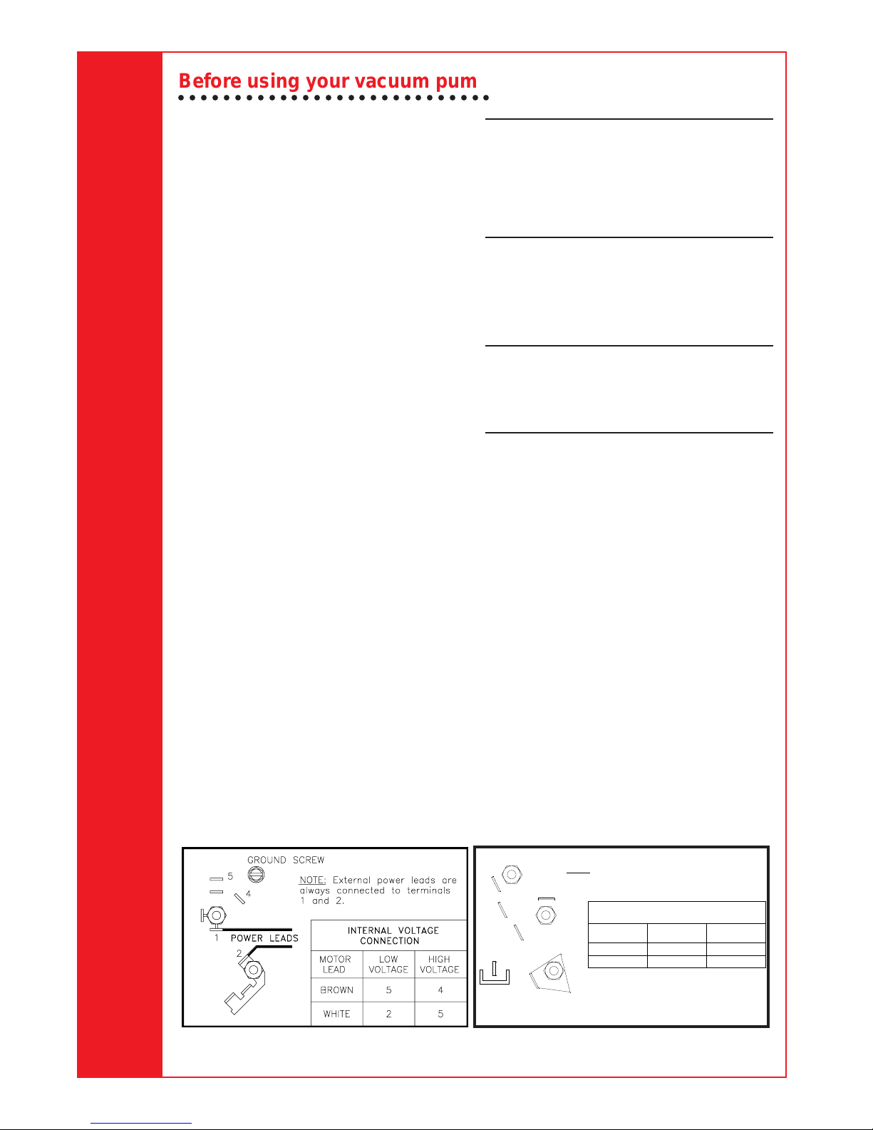
Wiring Instructions:
The CoolTech vacuum pump features dual
voltage ranges. Before operating the pump, read
and follow these rewiring instructions (if necessary) to be sure your pump is wired for the
appropriate voltage.
CAUTION! Unplug the unit before beginning
any service work. Improper use or connections can cause electrical shock. Only
qualified personnel should perform service
work.
The CoolTech vacuum pump is factory wired for a
high voltage range of 220 to 250 volts. To wire
the switch for a low voltage range of 110 volts to
115 volts, follow these steps.
1. Disconnect the unit from the AC power
source before proceeding.
2. Loosen the screws on the plate at the rear of
the motor, and carefully move the plate aside
to clear the opening.
3. Disconnect the leads and reconnect for low
voltage, following the diagram and chart.
(High voltage connections are also shown
if you want to rewire at some time.)
4. Check to see that all connections are
secure and that there are no short circuits.
Be sure the grounding connector is properly
connected.
5. Re-install the plate on the rear of motor with
the screws which were loosened in Step 2.
IMPORTANT: Check for short circuits using a
continuity tester before reconnecting to the AC
power source.
4
NOTE: EXTERNAL POWER LEADS ARE ALWAYS
3
2
5
6
1
4
CONNECTED TO TERMINALS 1 AND 4.
- EMERSON -
INTERNAL VOLTAGE CONNECTION
MOTOR
LEAD VOLTAGE
WHITE 4 3
LOW HIGH
3BROWN 6
VOLTAGE
INST0350
Emerson MotorsGeneral Electric Motors
Page 5

To use the gas
ballast feature
○○○○○○○○○○○○
To maintain your high
vacuum pump
○○○○○○○○○○○○
Moisture from the A/C-R system that is carried
into the pump as a vapor tends to condense into a
liquid and combine with the vacuum pump oil.
When moisture contaminates the pump oil, it
reduces the pump’s ability to reach its ultimate
deep vacuum level.
The gas ballast valve purges a small amount of
atmospheric air through the exhaust chamber.
This extra volume of air mixes with the vapor from
the refrigerant system to prevent condensation
and to help exhaust moisture in the form of vapor
from the pump.
To use the gas ballast, start the pump and open
the gas ballast valve until the system has reached
approximately 1000-3000 microns. Close the
valve to allow the pump to pull down to its
ultimate vacuum level. The gas ballast valve is
located beside the handle, opposite the inlet
fitting.
The gas ballast valve may be opened or closed at
any time during pump operation. It is fully open at
two turns counterclockwise.
NOTE:
Robinair recommends the use of a
thermistor vacuum gauge to most accurately
measure vacuum levels.
To shut down your
pump after use
○○○○○○○○○○○○○
To help prolong pump life and promote easy
starting, follow these procedures for shutdown:
1. Close the manifold valve between the pump
and the system.
2. Turn the Iso-Valve to the CLOSED position.
3. Remove the hose from the pump inlet.
4. Turn the pump power switch to OFF, then
return the Iso-Valve to the OPEN position for
a few seconds to relieve any vacuum inside
the pump.
5. Cap the inlet port to prevent any contamination or loose particles from entering the port.
For maximum performance, Robinair recommends
changing vacuum pump oil after each use.
Vacuum pump oil
The condition and type of oil used in any high
vacuum pump are extremely important in determining the ultimate attainable vacuum. Robinair recommends the use of our Premium High Vacuum Pump
Oil. This oil has been specifically blended to maintain
maximum viscosity at normal running temperatures
and to improve cold weather starts.
Robinair Premium High Vacuum Pump Oil is
available in handy quart containers or in convenient gallon containers. Order by part number:
13203 — Quart (shipped 12 quarts per case)
13204 — Gallon (shipped 4 gallons per case)
Oil change procedure
1. Be sure the pump is warmed up.
2. Remove the OIL DRAIN cap. Drain contaminated oil into a suitable container and dispose
of properly. Oil can be forced from the pump
by opening the inlet and partially blocking the
exhaust with a cloth while the pump is
running. Do not operate the pump for more
than 20 seconds using this method.
3. When the flow of oil has stopped, tilt the
pump forward to drain residual oil.
4. Replace the OIL DRAIN cap. Remove the OIL
FILL cap and fill the reservoir with new
vacuum pump oil until the oil just shows at the
bottom of the sight glass. The approximate oil
capacity of the pump is 375 milliliters.
5. Be sure the inlet ports are capped, then turn
ON the pump. Allow it to run for one minute,
then check the oil level. If the oil is below the
sight glass OIL LEVEL line, add oil slowly
(with the pump running) until the oil reaches
the OIL LEVEL line. Replace the OIL FILL
cap, making sure the inlet is capped and the
drain cap is tight.
6. If the oil is badly contaminated, you may need
to flush your pump. To flush, remove the
pump drain cap and start the pump. Slowly
pour a small quantity of new pump oil through
the oil fill inlet.
Repeat this procedure as required until the
contamination is removed. Replace the OIL
DRAIN cap and refill the reservoir to the proper
level with fresh pump oil (see Step 4).
Cleaning your pump
Clean the pump with soap and water only. Do not
use commercial cleaners that contain degreasing
agents that can damage polycarbonates. The
pump handle and base are made of Lexan, one of
the toughest polycarbonate plastics available.
However, it is sensitive to degreasing agents.
*Lexan is a registered trademark of General Electric
Motor Lubrication
After three years of normal service or one year of
heavy-duty service, add oil annually. Use electric
motor oil or SAE 10 oil.
Operating Manual
5
Page 6

T roubleshooting guide
○○○○○○○○○○○○○○○○○○○
Your CoolTech pump has been designed for
dependable use and long life. If something should
go wrong, however, the following guide will help
you get the pump back into service as quickly as
possible.
If disassembly of the pump is required, please
check your warranty. The warranty may be
voided by misuse or customer tampering which
results in the pump being inoperable.
Failure to start
Check the line voltage. Robinair pumps are
designed to start at
o
C. At extremes, however, switching between
0
the start and run windings may occur. When
starting the pump in cold temperatures, be sure
the Iso-Valve and inlet port are open to free air.
Oil leakage
1. Be sure the oil is not a residual accumulation
from spillage, etc.
2. If leakage exists, the module cover gasket or
the shaft seal may need replacing. Follow the
instructions supplied with the seal replacement kit, part number 15367. If leakage
exists in the area of the drain plug, you may
need to reseal the plug using a commercial
pipe thread sealer.
Failure to pull a good vacuum
1. Be sure the Iso-Valve on the pump is in the
OPEN position and the gas ballast knob is
tightly sealed.
2. Be sure the vacuum gauge and all connections are in good conditon and leak-free.
You can confirm leakage by monitoring the
vacuum with a thermistor gauge while
applying vacuum pump oil at connections or
suspected leak points. The vacuum will
improve briefly while the oil is sealing the
leak.
3. Be sure the pump oil is clean. A badly
Operating Manual
contaminated pump may require several oil
flushes. See OIL CHANGE PROCEDURE.
4. Be sure the oil is at the proper level. For
maximum pump operation, the oil must be
even with the OIL LEVEL line on the sight
glass when the pump is running. See OIL
CHANGE PROCEDURE. Do not overfill —
operating temperatures will cause the oil to
expand so it will appear at a higher level than
when the pump is not running. To check the
oil level, start the pump with the inlet capped.
Check the oil level in the sight glass. Add oil
if necessary.
+10% line voltage (loaded) at
U.S Patents 4,523,897; 5,209.653. Other U.S.
and Foreign Patents Pending.
6
CoolTech ® pump
specifications
○○○○○○○○○○○○
Frequency Range ................................... 50-60 Hz
Free Air Displacement ....................... 4 cfm/60 Hz
................................................. 94 l/m @50 Hz
............................................... 113 l/m @60 Hz
Stages................................................................. 2
Motor Speed ............................1425 rpm @50 Hz
............................................1725 rpm @60 Hz
Voltage Range .......................................110-115V
..........................................................220-250V
Factory Micron Rating .........................20 microns
Approximate Oil Capacity ........................... 400 ml
Weight...........................................................15 kg
Width ...................................................... 14.29 cm
Height ....................................................... 24.6 cm
Length .......................................................... 40 cm
Intake ..................................
Min. Starting Temp. (at 90% Voltage)............. 0oC
Motor Size ...........0.25kW (
Operating Temp. ............................................ 68oC
Frequency Range ................................... 50-60 Hz
Free Air Displacement ....................... 6 cfm/60 Hz
............................................... 142 l/m @50 Hz
............................................... 170 l/m @60 Hz
Stages................................................................. 2
Motor Speed ............................1425 rpm @50 Hz
............................................1725 rpm @60 Hz
Voltage Range .......................................110-115V
..........................................................220-250V
Factory Micron Rating .........................20 microns
Approximate Oil Capacity ........................... 400 ml
Weight....................................................... 15.2 kg
Width ...................................................... 14.29 cm
Height ....................................................... 24.6 cm
Length .......................................................... 42 cm
Intake ..................................
Min. Starting Temp. (at 90% Voltage)............. 0oC
Motor Size....... 0.375 kW (1/2 HP) Capacitor Start
Operating Temp. ............................................ 68
Note:
1. All motors are internally protected (automatic
reset).
2. Operating temperatures are typical for
normal operating conditions.
3. Model 15603 has a bipolar side grounded plug.
4. 15405 & 15605 have an Australian plug.
Because of ongoing product improvements, we reserve the right to
change design, specifications, or materials without notice.
Model 15401
1
/2” and 1/4” SAE MFL
1
/3 HP) Capacitor Start
Model 15601/15603/15605
1
/2” and 1/4” SAE MFL
o
C
Page 7
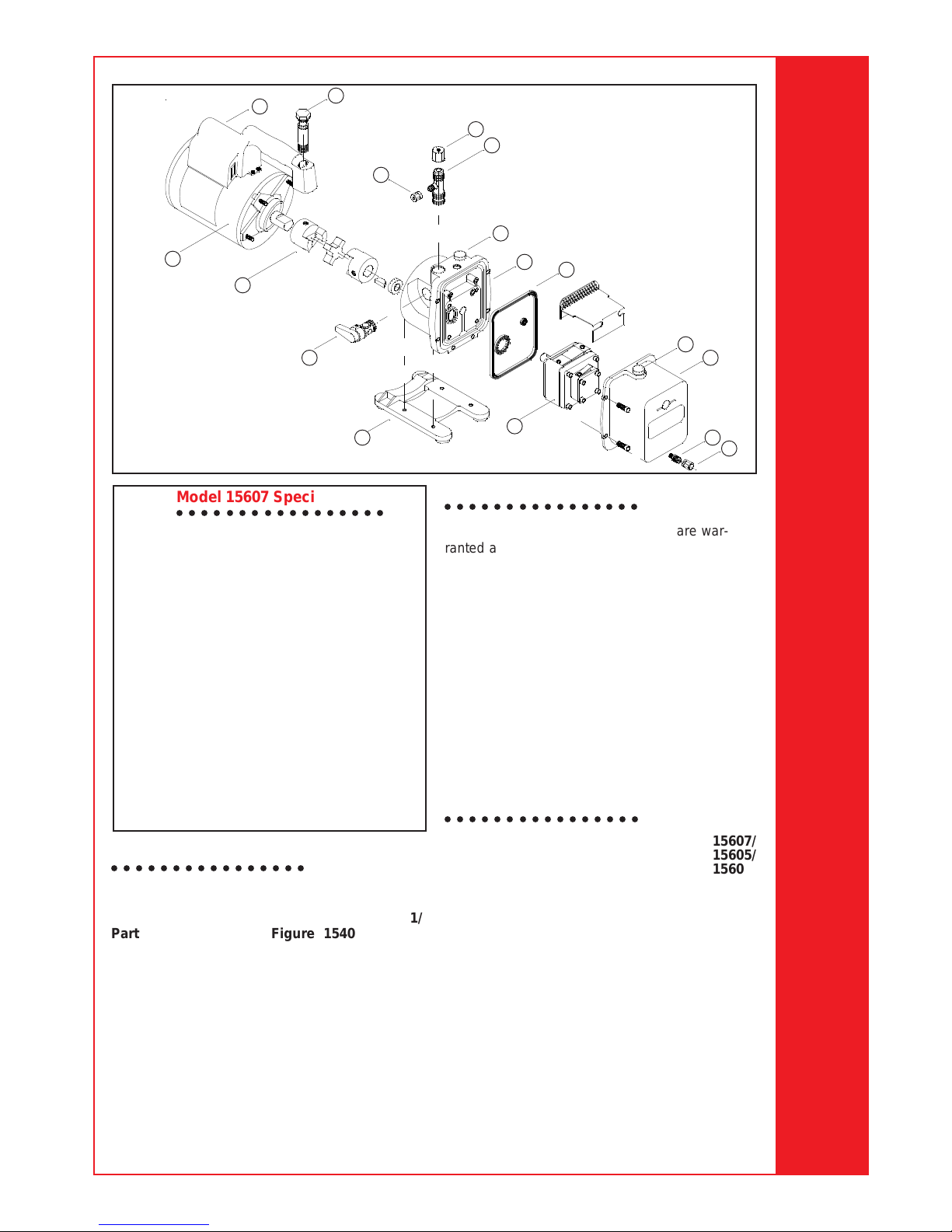
12
13
14
11
9
8
10
7
6
5
4
15
3
Operating Manual
16
INST0026
Model 15607 Specifications
○○○○○○○○○○○○○○○○○
Voltage Range 220V
Frequency Range 50 Hz.
Free Air Replacement 142 l/m
Stages 2
Motor Speed 1425 rpm
Factory Micron Rating 20 microns
Approximate Oil Capacity 400 ml
Weight 15 kg.
Width 14.29 cm.
Height 24.6 cm.
Length 42 cm.
Intake 1/2"and 1/4"
SAE MFL
Min. Starting Temp. at 90% Voltage 0oC
Motor Size .37kW (1/2 hp)
Capacitor Start
Operating Temperature 68oC
Replacement parts
○○○○○○○○○○○○○○○○
15607/
15605/
15601/
Part Figure 15401 15603
Oil Drain Cap (6) 1 40572 40572
Oil Drain Kit
(includes No. 1) 2 48116 48116
Module Cover Kit
(includes No. 2, 4 and 5) 3 15337 15337
Oil Fill Cap
(includes No. 7) 4 15371 15371
Intake Fitting
(includes No. 9 and 10) 8 15364 15364
Intake Cap (2),
1
/2” SAE MFL 9 41135 41135
17
INST0026
Warranty co verage
○○○○○○○○○○○○○○○○
2
1
Robinair CoolTech® vacuum pumps are warranted against defects in material and workmanship for one year of normal use from the date of
purchase. See your distributor for warranty
details.
Out of warranty
A pump which is no longer covered by the oneyear warranty period and which fails to operate
properly should be returned to the distributor with
a full written explanation of the problem. The
distributor may suggest returning the pump to the
factory. Before returning an out-of-warranty
pump, review all maintenance procedures to
avoid an unnecessary return. Replacement parts
are available for doing your own service.
Replacement parts
○○○○○○○○○○○○○○○○
15607/
15605/
15601/
Part Figure 15401 15603
Intake Cap (6),
1
/4” SAE MFL 10 41139 41139
Vent Bolt
(includes O-rings) 11 15338 15338
Handle, Power Cord
and Switch Assembly 12 15466 15466
Motor 13 15465 15665
Coupling 14 48103 48103
TM
Iso-Valve
Assembly 15 15368 15368
Base and Foot Assembly 16 15369 15369
Pump Assembly, less motor
(includes No. 3 and 6) 17 15547 15548
Seal Replacement Kit
(not shown) -- 15367 15367
7
Page 8

Contenido
○○○○○○○○○
Bombas de vacío de alto rendimiento CoolTech®8
Componentes de la bomba ................................ 9
Advertencias ....................................................... 9
Antes de utilizar su bomba de vacío ................ 1 0
Para utilizar el balasto de gas .......................... 11
Para apagar la bomba después de utilizarla.... 1 1
Para mantener su bomba de alto vacío ........... 12
Aceite de la bomba de vacío ....................... 1 2
Procedimiento para cambios de aceite ....... 12
Limpieza de la bomba.................................. 12
Lubricación de motor ................................... 12
Guía para la resolución de problemas ............. 1 3
Fallas de arranque ....................................... 13
Fugas de aceite ........................................... 13
Vacío deficiente ........................................... 13
Repuestos......................................................... 14
Cobertura de la garantía .................................. 14
Período de garantía ..................................... 14
Especificaciones de las bombas
CoolTech
®
......................................................... 15
Para los sistemas A/C-R que
utilizan los CFC, HCFC, y HFC
en combinación con aceite
mineral, aceite de éster, aceite
aiquilbenceno y aceite PAG
como lubricantes. No para uso
con sistemas de amoníaco o
bromuro de litio. No para uso
con refrigerantes combus-
tibles.
Manual del Operador
Bombas de vacío de alto
rendimiento CoolT ech
○○○○○○○○○○○○○○○○○○○
Felicitaciones por su compra de una bomba
de vacío CoolTech
Robinair. Su bomba ha sido diseñada específicamente para servicios de aire acondicionado
y refrigeración y está construida con el álabe
rotatorio compensado de la Robinair para tener
una comprobada evacuación rápida y completa.
Ud. va a apreciar estas características...
Iso-Valve
Permite que la bomba se cierre mientras está
conectada todavía al sistema de A/C-R, lo cual
es conveniente para controlar el ritmo de
aumento. Con el mango de la válvula en la
posición “Open,” la bomba está abierta al sistema
que está siendo evacuado. En la posición
“Close,” la bomba está aislada del sistema. Esto
minimiza la cantidad de aceite de la bomba
llevado al módulo de bombeo, facilitando el
arranque de la bomba y disminuyendo el
desgaste de sus componentes.
Alto vacío nominal
El diseño del álabe rotatorio compensado de dos
etapas ofrece una capacidad de alto vacío
poderosa, pero silenciosa, y asegura la
eliminación de la humedad, mientras que la
fuerte capacidad de bombeo reduce el tiempo de
evacuación.
Filtración durante la Vida Util
El filtro de entrada evita que materias extrañas
entren a la cámara de bombeo, y un filtro interno
de escape separa el vapor de aceite del flujo de
escape.
Escape dirigido
El escape se expulsa a través del mango para
dirigirlo en sentido contrario al técnico de
servicio.
Balasto de gas
Una cantidad precisa de aire atmosférico se
introduce en la bomba, previniendo la condensación del vapor de humedad y ayudando a mantener la pureza del aceite de la bomba. Al utilizar
el balasto de gas, la bomba opera con mayor
eficiencia y se extiende la vida de la bomba.
Mango de agarre seguro
El mango moldeado de una sola pieza hace que
sea fácil de transportar la bomba a diferentes
lugares de trabajo, y no se calienta durante la
operación.
Diseño compacto
Su bomba mide aproximadamente 40 cm de
largo, y la caja de aluminio y álabes rotatorios
compensados aligeran el peso de la bomba,
haciéndola fácil de llevar.
TM
®
de óptima calidad de
®
8
Page 9

Manual del Operador
Componentes de la bomba
1. Conectador de la Entrada
2. Válvula de Balasto de Gas (ubicada al lado
de la base del mango)
3. Puerto para el Llenado de Aceite
4. Tubo Indicador
5. Caja Moldeada de Aluminio
6. Drenaje de Aceite
7. Base Moldeada de Policarbonatos
8. Iso-Valve
9. Potente Motor de Alto Torque
10. Interruptor Eléctrico
11. Escape por el Mango
12. Mango de Agarre Seguro
TM
— aísla la bomba del sistema
Advertencias
○○○○○○○○○○○
Cuando se trabaja con refrigerantes, siempre se
debe usar gafas protectoras. El contacto con
refrigerantes puede causar daños a su persona.
El uso o conexiones inadecuados pueden crear
situaciones de peligro de shock eléctrico. Lea y
siga las instrucciones cuidadosamente y tome
precauciones para evitar estos peligros.
Asegúrese de que todos los dispositivos
asociados estén adecuadamente conectados a
tierra antes de pasar energía a los circuitos.
La temperatura normal de operación hará que
ciertas porciones externas de la bomba se
calienten. No toque la caja de la bomba o el motor
durante su operación.
NOTICIA: Emisiones Aerotransportadas de Ruido
Este equipo ha sido probado para emisiones aerotransportadas
de ruido según la Directiva del Consejo para Maquinaria (89/392/
EEC), Sección 1.7.4 Instrucciones — Requisitos Esenciales de
Salud y Seguridad. El nivel de ruido no sobrepasa el valor
actual de 88dB(A).
9
Page 10

Antes de utilizar su bomba de vacío
○○○○○○○○○○○○○○○○○○○○○○○○○○○○○○
En todos los casos, los motores están diseñados
para voltajes de trabajo con una variación del
+10% del valor nominal (ver ESPECIFICACIONES).
1. Asegúrese de que el voltaje y la frecuencia
en la salida se conformen con las especificaciones en la calcomanía del motor de la
bomba. Revise el interruptor (ON-OFF) para
asegurar que está en la posición de OFF
antes de enchufar la bomba. Verifique que la
válvula de balasto de gas esté cerrada.
Saque y bote el tapón de escape del mango.
2. La bomba se envía sin aceite en el
reservorio; antes de arrancarla, hay que
llenarlo de aceite. Saque la tapa OIL FILL
(un tapón hecho de plástico negro que está
directamente al frente al mango) y agregue
aceite justamente hasta que aparezca en el
fondo del tubo indicador. La bomba tiene una
capacidad aproximada de aceite de 375 ml.
3. Reemplace la tapa de LLENADO DE ACEITE
(Oil Fill), y remueva la tapa de uno de los
puertos de entrada. Ponga la Iso-válvula en
la posición ABIERTO (Open). Gire el
interruptor de motor a ENCENDIDO (On).
Cuando la bomba funcione suavemente,
ponga la Iso-válvula en la posición
CERRADO (Closed) y reemplace la tapa del
puerto de entrada. Esto puede requerir de
dos a 30 segundos dependiendo de la
temperatura ambiente. Después de que la
bomba funcione por aproximadamente un
minuto, verifique el nivel adecuado del aceite
en el cristal visor — el aceite debe estar
nivelado con la línea de NIVEL DE ACEITE
(Oil level) del cristal visor. Añada más aceite
si es necesario.
Cuando la bomba está funcionando, el aceite
debe estar al nivel de la línea del tubo indicador.
Una cantidad demasiado baja resultará en un
vacío deficiente. Una cantidad demasiado grande
resultará en la salida de aceite por el escape.
Manual del Operador
Ahora su bomba está lista para evacuar sistemas
de aire acondicionado y refrigeración. Para
conectar la bomba al sistema, siga los
procedimientos normales de servicio y las
instrucciones del fabricante.
CUIDADO! Antes de conectar la bomba de
vacío al sistema de A/C-R, elimine el
refrigerante del sistema de una manera
aceptable. Pueden producirse daños en la
bomba si se inicia la evacuación mientras el
sistema está bajo mucha presión. La Robinair
recomienda el uso de nuestros equipos de
Recuperación y Reciclaje de Refrigerantes.
Instrucciones para la instalación
alámbrica del interruptor:
Los bombas de vacío CoolTechofrecen rangos
duales de voltaje. Antes de operar la bomba, lea
y siga estas instrucciones para cambios de
alambrado (si esto fuera necesario) para
asegurar que su bomba esté preparada para el
voltaje apropiado.
CUIDADO! Desenchufe la unidad antes de
iniciar cualquier trabajo de servicio. El uso o
conexiones inadecuados pueden causar
shock eléctrico. Solamente personal
calificado debe realizar trabajos de servicio.
Los bombas de vacío CoolTech vienen de la
fábrica listos para un rango de alto voltaje de 200
a 250 voltios. Para cambiar el alambrado a un
rango de bajo voltaje de 100 a 115 voltios, siga
estos pasos:
1. Desconecte la unidad de la fuente de poder
de corriente alterna (AC) antes de proceder.
2. Afloje los tornillos de la placa en el lado
posterior del motor y coloque cuidadosamente a un lado la placa para despejar la
entrada.
3. Desconecte los avances y reconecte para el
bajo voltaje, siguiendo el diagrama y el
cuadro en la siguiente página. (Las
conexiones de alto voltaje también están
indicadas por si acaso quisiera volver a la
configuración original alguna vez.)
4. Verifique que las todas las conexiones estén
bien sujetadas y que no haya cortocircuitos.
También de que la conexión a tierra esté
bien hecha.
5. Reinstale la placa en el lado posterior del
motor con los tornillos que se aflojaron en el
paso 2.
IMPORTANTE: Antes de volver a conectar con
la fuente de poder, revise para ver si hay
cortocircuitos utilizando un medidor de
continuidad.
10
Page 11

1
2
4
3
5 6 7
8
9
La bomba de General Electric
À Tornillo Para La
Puesta A Tierra
Á
Nota:
Las conexiones
eléctricas externas siempre
se conectan con las terminales
1 y 2.
 Avances Eléctricos
Para utilizar el
balasto de gas
○○○○○○○○○○○○
La humedad que la bomba se lleva del sistema
A/C-R, en forma de vapor, tiende a condensarse
y este líquido se une al aceite de la bomba de
vacío. Cuando el aceite de la bomba se
contamina de humedad, esto reduce la capacidad
de la bomba de alcanzar su máximo nivel de alto
vacío.
La válvula del balasto de gas purga una pequeña
cantidad de aire atmosférico a través de la
cámara de escape. Este volumen adicional de
aire se mezcla con el vapor del sistema de
refrigerante para evitar la condensación y facilitar
la salida de humedad de la bomba en forma de
vapor.
Para utilizar el balasto de gas, arranque la bomba
y abra la válvula de balasto de gas hasta que el
sistema haya llegado a aproximadamente
1000-3000 (mil) micrones. Cierre la válvula para
permitir que la bomba llegue a su máximo nivel de
vacío. La válvula del balasto de gas está ubicada
al lado del mango, frente al conectador de la
entrada.
La válvula del balasto de gas puede estar abierta
o cerrada en cualquier momento durante la
operación de la bomba. Está totalmente abierta
con dos vueltas en la dirección contraria al
movimiento de las manecillas del reloj.
NOTA:
La Robinair recomienda el uso de un
manómetro de vacío tipo termistor para medir los
niveles de vacío de la manera más precisa.
La bomba de Emerson
à Conexión Interna De
Voltaje
Ä Avance Del Motor
Å Bajo Voltaje
Æ Alto Voltaje
Ç Marrón
È Blanco
É Púrpura
Para apagar la
bomba después de utilizarla
○○○○○○○○○○○○○○○○○○○○○○○○
Para ayudar a prolongar la vida útil de la bomba y
facilitar el arranque, siga estos procedimientos
para apagarla.
1. Cierre la válvula del múltiple entre la bomba y
el sistema.
2. Ponga la Iso-válvula en la posición
CERRADO (Closed).
3. Remueva la manguera de la entrada de la
bomba.
4. Ponga el interruptor de energía para la
bomba en la posición PARADO (Off), luego
ponga la Iso-válvula en la posición ABIERTO
(Open) de nuevo, por unos segundos para
eliminar el vacío del interior de la bomba.
5. Tape el puerto de entrada para prevenir
cualquier contaminación o entrada de
partículas flojas en el puerto.
Manual del Operador
11
Page 12

Para mantener su bomba de alto vacío
○○○○○○○○○○○○○○○○○○○○○○○○○○○○○○○○
Para un máximo rendimiento, Robinair
recomienda que se cambie el aceite de la bomba
de vacío después de cada uso.
Aceite de la bomba de vacío
La condición y el tipo de aceite utilizado en
cualquier bomba de alto vacío son sumamente
importantes en la determinación del máximo vacío
alcanzable. Robinair recomienda el uso de
nuestro Aceite Premium para Bombas de Alto
Vacío. Este aceite ha sido mezclado
específicamente para mantener la viscosidad
máxima a temperaturas normales de trabajo y
para mejorar los arranques en temporadas frías.
Se dispone del Aceite Premium para Bombas de
Alto Vacío Robinair en recipientes convenientes
de un galón o cuarto de galón. Haga los pedidos
por los números de repuesto:
13203 — Cuartos (enviados 12 cuartos por caja)
13204 — Galón (enviados 4 galones por caja)
Procedimiento para cambios de aceite
1. Asegúrese de calentar la bomba.
2. Saque la tapa OIL DRAIN. Drene el aceite
contaminado en un recipiente apropiado y
disponga del mismo adecuadamente. El
aceite puede ser forzado a salir de la bomba
al abrir la entrada y bloquear parcialmente el
escape con una tela mientras la bomba está
funcionando. No opere la bomba por más de
20 segundos utilizando este método.
3. Cuando se haya detenido el flujo de aceite,
incline la bomba hacia adelante para drenar
el aceite residual.
4. Vuelva a colocar la tapa OIL DRAIN. Saque
la tapa OIL FILL y llene el reservorio con el
nuevo aceite para bombas de vacío
justamente hasta que aparezca en el fondo
del tubo indicador. La bomba tiene una
capacidad aproximada de aceite de 375 ml.
5. Asegúrese de que estén tapados los puertos
de entrada y luego encienda la bomba
(póngala en ON). Permita que funcione
durante un minuto y luego revise el nivel del
aceite. Si el aceite está por debajo de la línea
OIL LEVEL, agregue más aceite lentamente
(mientras funciona la bomba) hasta que
alcance la línea. Vuelva a poner la tapa OIL
FILL, asegurándose de que la entrada esté
tapada y que la tapa del drenaje esté bien
ajustada.
6. Si el aceite está muy contaminado, puede ser
necesario enjuagar la bomba. Para hacerlo,
saque la tapa del drenaje de la bomba y
arranque la bomba. Lentamente vierta una
pequeña cantidad de nuevo aceite para
bombas por el puerto para el llenado de
aceite.
Repita este procedimiento las veces que sean
necesarias hasta que se elimine la contaminación. Vuelva a colocar la tapa OIL DRAIN y vuelva
a llenar el reservorio con aceite fresco para
bombas hasta el nivel apropiado (ver el paso 4).
Limpieza de la bomba
Limpie la bomba con agua y jabón. No utilice los
limpiadores comerciales que contienen agentes
desengrasadores que pueden dañar los
policarbonatos. La manilla y la base de la bomba
son construidas de Lexan, uno de los plásticos
policarbonatos más duros. Sin embargo es
sensible a los agentes desengrasadores.
*Lexan es una marca registrada de General Electric
Lubricación de motor
Después de tres años de servicio normal o un año
de servicio pesado, añada aceite anualmente.
Use aceite de motor eléctrico o aceite SAE 10.
Manual del Operador
12
Page 13

Guía para la resolución de problemas
○○○○○○○○○○○○○○○○○○○○○○○○○○○○○○○○
Su bomba CoolTech ha sido diseñada para
ofrecer un servicio confiable y una larga vida útil.
Sin embargo, si hubiera una falla, la siguiente
guía le ayudará a tener la bomba funcionando de
nuevo lo más rápidamente posible.
Si se requiere desmontar la bomba, favor de
revisar su garantía. La garantía puede ser
anulada por la mala utilización o por trabajos
realizados por personas no autorizadas,
incluyendo al cliente, cuando estos resultan en la
inoperabilidad de la bomba.
Fallas de arranque
Revise el voltaje de la línea eléctrica. Las
bombas Robinair están diseñadas para arrancar
o
C a un voltaje de línea (cargada) con una
a 0
variación de
condiciones extremas, pueden producirse
conmutación entre los bobinados de arranque y
de operación. Cuando encienda la bomba en
bajas temperaturas, asegúrese de que la Isoválvula y el puerto de entrada estén expuestos al
aire libre.
Fugas de aceite
1. Asegúrese de que el aceite no sea residuos
de un derrame, etc.
2. Si existe una fuga, puede ser necesario
reemplazar el empaque de la tapa del
módulo o el sello del eje. Siga las
instrucciones suministradas con el juego de
repuesto del sello, repuesto número 15367.
Si existe una fuga en el área del tapón de
drenaje, puede ser necesario volver a
sellarlo utilizando un sellador comercial para
la rosca de la tubería.
+10%. Sin embargo, bajo
Vacío deficiente
1. Asegúrese de que la Iso-Valve de la bomba
esté en la posición abierta (OPEN) y que la
manilla de balasto de gas esté
completamente sellada.
2. Asegúrese de que el manómetro de vacío y
todas las conexiones estén en buen estado y
libre de fugas. Se puede confirmar una fuga
a través de un manómetro tipo termistor
mientras se vaya aplicando aceite para
bombas de vacío en las conexiones o los
puntos en donde se sospecha que pueda
presentarse una fuga.
3. Asegúrese de que el aceite de la bomba esté
limpio. Una bomba muy contaminada puede
requerir varios enjuagues de aceite. Ver el
PROCEDIMIENTO PARA CAMBIOS DE
ACEITE.
4. Asegúrese de que el aceite esté en el nivel
apropiado. Para el máximo rendimiento de la
bomba, el aceite tiene que estar en el nivel
de la línea OIL LEVEL en el tubo indicador
cuando la bomba está funcionando. Ver el
PROCEDIMIENTO PARA CAMBIOS DE
ACEITE. No cargue la bomba con
demasiado aceite — las temperaturas de
trabajo causarán la expansión del aceite, el
cual aparecerá en un nivel más alto que
cuando la bomba no está funcionando. Para
revisar el nivel del aceite, arranque la bomba
con la entrada tapada. Agregue aceite si es
necesario.
Manual del Operador
13
Page 14

12
13
14
11
9
8
10
7
6
5
4
15
3
16
INST0026
Repuestos
○○○○○○○○○
15601/
Repuesto Figura 15401 15603
Tapa para Drenaje
de Aceite (6) 1 40572 40572
Juego de Drenaje de
Aceite (incluye #1) 2 48116 48116
Juego de Cubierta de
Módulo (incluye #2, #4, #5) 3 15337 15337
Tapa para Llenado de
Aceite (incluye #7) 4 15371 15371
Conectador de Entrada
(incluye #9 y #10) 8 15364 15364
Tapa de Entrada (2),
1
/2" SAE MFL 9 41135 41135
Tapa de Entrada (6),
1
/4" SAE MFL 10 41139 41139
Cobertura de la garantía
○○○○○○○○○○○○○○○○○○○○
Las bombas de vacío CoolTech de Robinair
están garantizadas contra defectos de materiales
y fabricación durante un año de uso normal
desde la fecha de adquisición. Para los detalles
de la garantía, comuníquese con el distribuidor.
Período de garantía
Una bomba que ya no esté cubierta por el
período de garantía de un año que deje de
funcionar adecuadamente debe ser devuelta al
distribuidor con una explicación completa del
problema por escrito. Antes de devolver una
bomba sin garantía, revise todos los
procedimientos de mantenimiento para evitar la
devolución innecesaria. Están disponibles
repuestos para que usted realice su propio
servicio de mantenimiento.
17
INST0026
Tuerca de Ventilación
(incluye juntas tóricas) 11 15338 15338
Manual del Operador
Conjunto Mango-Cable
Eléctrico-Interruptor 12 15466 15466
Motor 13 15465 15665
Acople 14 48103 48103
Conjunto de Válvula
TM
(Iso-Valve
) 15 15368 15368
Conjunto Base-Pie 16 15369 15369
Conjunto de Bomba, no motor
(incluye #3 y #6) 17 15547 15548
Juego de Reemplazo
del Sello (no ilustrado) -- 15367 15367
2
1
14
Page 15

Especificaciones de las bombas CoolT ech
○○○○○○○○○○○○○○○○○○○○○○○○○○○○○○○○○○○○
®
Modelo 15401
Rango de Frecuencia.............................. 50-60 Hz
Desplazamiento Libre de Aire ............ 4 cfm/60 Hz
..................................................94 l/m @50 Hz
................................................113 l/m @60 Hz
Etapas ..................................................................2
Velocidad de Motor ................. 1.425 rpm @50 Hz
........................................... 1.725 rpm @60 Hz
Rango de Voltaje ................................... 110-115V
.......................................................... 220-250V
Valor Nominal de la Fábrica............... 20 micrones
Capacidad Aprox. de Aceite .......................375 ml
Peso .............................................................. 15 kg
Anchura...................................................14,29 cm
Altura.........................................................24,6 cm
Longitud .......................................................40 cm
1
Entrada ....................................
Temp. Mínima de Arranque
(a voltaje de 90%) ............................................0
Tamaño del Motor ........................................1/3 HP
Temp. de Trabajo...........................................68
/2” y 1/4” SAE MFL
o
Arranque por Capacitor
o
Modelo 15601/15603
Rango de Frecuencia.............................. 50-60 Hz
Desplazamiento Libre de Aire ............ 6 cfm/60 Hz
................................................142 l/m @50 Hz
................................................170 l/m @60 Hz
Etapas ..................................................................2
Velocidad de Motor ................. 1.425 rpm @50 Hz
........................................... 1.725 rpm @60 Hz
Rango de Voltaje ................................... 110-115V
.......................................................... 220-250V
Valor Nominal de la Fábrica............... 20 micrones
Capacidad Aprox. de Aceite .......................375 ml
Peso ........................................................... 15,2 kg
Anchura...................................................14,29 cm
Altura.........................................................24,6 cm
Longitud .......................................................42 cm
1
Entrada ....................................
Temp. Mínima de Arranque
(a voltaje de 90%) ............................................0
C
Tamaño del Motor ........................................1/2 HP
C
Temp. de Trabajo...........................................68
/2” y 1/4” SAE MFL
Arranque por Capacitor
Nota:
1. Todos los motores llevan protección interna
(con reactivación automática).
2. Las temperaturas de trabajo son típicas para
condiciones normales de operación.
3. El Modelo 15603 tiene un enchufe lateral
bipolar puesto a tierra.
Patentes EE.UU. 4.523.897; 5,209.653. Otras
patentes pendientes en los Estados Unidos y
otros países.
Debido al continuo mejoramiento de los
productos, nos reservamos el derecho de
cambiar diseños, especificaciones y
materiales sin previo aviso.
Manual del Operador
o
C
o
C
15
Page 16

Sommaire
○○○○○○○○○
Pompes à vide CoolTech
à haut rendement ............................................. 16
Composants de la pompe ................................ 17
Avertissements ................................................. 17
Avant d’utiliser la pompe à vide........................ 18
Utilisation du dispositif de lest de gaz .............. 19
Arrêt de la pompe après usage........................ 19
Entretien de la pompe à vide
à haut rendement ............................................. 20
Huile de la pompe à vide ............................. 20
Instructions pour le changement d’huile...... 2 0
Nettoyage de la pompe ............................... 20
Lubrification de moteur ................................ 20
Guide de détection des pannes ........................ 21
La pompe ne démarre pas ............................... 21
Il y a une fuite d’huile ................................... 21
Il est impossible d’obtenir
un haut niveau de vide................................. 21
Pièces de rechange .......................................... 22
Garantie ............................................................ 22
Hors garantie ............................................... 22
Spécifications de la pompe CoolTech
®
®
............. 23
Pour les systèmes A/C-R,
utilisant les CFC, HCFC et HFC
en conjonction avec de l’huile
minérale, de l‘huile ester, de
l’huile de benzène d’alkyle et
de l’huile PAG comme
lubrifiants. Ne pas utiliser sur
les systèmes à ammoniaque
ou bromure de lithium. Ne pas
Manuel d’utilisation
utiliser avec des réfrigérants
inflammables.
Pompes à vide CoolTech
à haut rendement
○○○○○○○○○○○○○○○
Nous vous félicitons d’avoir opté pour un modèle
de pompes à vide CoolTech
Cette pompe a été spécifiquement conçue pour
entretenir les installations de climatisation et de
réfrigération et comporte un dispositif à ailettes
rotatives Robinair qui a fait ses preuves et qui
assure une évacuation rapide et complète.
Ces qualités sont là pour vous servir au mieux...
Soupape Iso-Valve
Elle permet d’arrêter la pompe tout en la laissant
branchée sur le système A/C-R, ce qui est
commode pour vérifier les niveaux. Lorsque la
manette de soupape est en position “Open,” la
pompe s’ouvre au système en cours
d’évacuation. Lorsqu’elle est en position “Close,”
elle est isolée du système. Ce dispositif permet
de limiter la quantité d’huile injectée dans le
module de pompage, facilite le démarrage et
réduit l’usure des composants de la pompe.
Régime nominal de vide poussé
Sa conception à deux étages et à deux ailettes
rotatives donne à la pompe une capacité de vide
puissante et silencieuse ainsi que la possibilité de
prélever l’humidité; cette forte capacité de
pompage réduit le temps d’évacuation.
Filtration et durée de vie
Le filtre d’aspiration retient toute matière
étrangère à l’entrée de la chambre de pompage
et un filtre d’échappement interne sépare la
vapeur d’huile du flux d’échappement.
Echappement dirigé
L’échappement s’effectue par la poignée et est
expulsé loin du technicien de maintenance.
Lest de gaz
Un volume précis d’air est introduit dans la
pompe, ce qui empêche la condensation de la
vapeur d’humidité et aide à maintenir la pureté de
l’huile. En utilisant le lest de gaz, la pompe opère
plus efficacement et sa durée de vie est
rallongée.
Poignée de prise sûre
Cette poignée moulée, faite d’une seule pièce,
facilite le transport de la pompe de chantier en
chantier. Elle reste froide lorsque la pompe
fonctionne.
Conception compacte
La pompe, qui mesure environ 40 cm de long, est
légère grâce à son boîtier en aluminium et ses
ailettes rotatives, et dès lors facile à transporter.
TM
®
®
de haute gamme.
16
Page 17

Manuel d’utilisation
Composants de la pompe
1. Raccord d’aspiration
2. Soupape de lest de gaz (située près du socle
de la poignée)
3. Orifice de remplissage d’huile
4. Hublot de regard
5. Boîtier en aluminium moulé
6. Orifice de vidange d’huile
7. Socle en polycarbonate moulé
8. Soupape Iso-Valve
pompe du système
9. Moteur puissant à fort couple
10. Interrupteur d’alimentation
11. Echappement par la poignée
12. Poignée à prise sûre
TM
— permet d’isoler la
Avertissements
○○○○○○○○○○○○○
Pour travailler avec des réfrigérants, le port de
lunettes protectrices est obligatoire car le contact
avec les réfrigérants peut occasionner des
blessures.
Une utilisation inappropriée ou des connexions mal
faites peuvent être sources de chocs électriques.
Lire soigneusement les instructions et prendre
toutes les précautions nécessaires pour éviter les
chocs électriques. S’assurer que tous les appareils
associés à la pompe sont correctement mis à la
masse avant de mettre les circuits sous tension.
La température normale de fonctionnement
provoquera le réchauffement de certaines parties
extérieures de la pompe. Ne pas toucher le boîtier
de la pompe ou le moteur pendant que la pompe
fonctionne.
NOTICE: Emissions de Bruits Aériens
Cet équipment a été testé pour les émissions de bruits aériens
selon la Directive du Conseil pour la Machinerie (89/392/EEC),
Section 1.7.4 Instructions — Prescriptions Essentielles de Santé
de Sécurité. Les niveaux sonores ne doivent pas excéder
88dB(A) en valeur effective.
17
Page 18

Avant d’utiliser la pompe à vide
○○○○○○○○○○○○○○○○○○○○○○○○○○
Dans tous les cas, les moteurs sont conçus pour
fonctionner avec des tensions de fonctionnement
de plus ou moins 10% de la tension nominale (cf.
SPECIFICATIONS).
1. Vérifier que les spécifications de tension et
de fréquence mentionnées sur la plaque
d’identification du moteur correspondent bien
à celles de la prise de courant. Faire attention que l’interrupteur ON-OFF soit en
position OFF avant de brancher la pompe
dans une prise. Vérifier que la soupape de
lest de gaz est fermée. Enlever et mettre de
côté le bouchon de l’échappement situé à
l’extrémité de la poignée de la pompe.
2. La pompe est livrée sans huile dans le
réservoir. Avant de démarrer la pompe, il
faut remplir le réservoir d’huile. Retirer le
bouchon de l’orifice de remplissage d’huile
(bouchon noir en plastique situé devant la
poignée) et ajouter de l’huile jusqu’à ce qu’on
la voit apparaître au fond du hublot de
regard. La capacité de la pompe en huile est
d’environ 375 millilitres.
3. Remettre le bouchon de remplissage d’huile
(OIL FILL) et enlever le bouchon de l’un des
orifices d’admission. Mettre la soupape Isovalve en position ouverte (OPEN). Placer le
commutateur moteur sur ON. Une fois la
pompe mise en route, mettre la soupape Isovalve en position fermée (CLOSED) et
replacer le capuchon sur l’orifice
d’admission. L’opération dure entre 2 et 30
secondes suivant la température ambiante.
Après avoir laissé la pompe fonctionner
pendant une minute environ, vérifier le
niveau d’huile dans le hublot de regard :
l’huile doit atteindre la ligne OIL LEVEL.
Ajouter de l’huile si nécessaire.
Lorsque la pompe fonctionne, le niveau d’huile
doit arriver au trait du hublot de regard. Si le
niveau est inférieur, le rendement sera moindre
en termes de vide réalisé. Si le niveau est
Manuel d’utilisation
supérieur, de l’huile s’échappera éventuellement
de l’orifice d’échappement.
La pompe est maintenant prête à évacuer les
systèmes de climatisation et de réfrigération.
Suivre les procédures normales d’entretien et les
instructions du fabricant de systèmes A/C-R
concernant le branchement de la pompe au
système.
ATTENTION! Avant de brancher la pompe à
vide sur un système A/C-R, retirer le réfrigérant
du système en suivant la méthode habituelle.
Si l’évacuation commence alors que le système
est sous haute pression, la pompe encourt des
dommages. Robinair recommande l’utilisation
de son équipement de récupération et de
recyclage du réfrigérant.
Instructions relatives au cablâge :
La pompe à vide CoolTech® est disponible en
bitension. Avant d’utiliser la pompe, lire et suivre
les instructions de recâblage (si nécessaire) afin
que la pompe soit réglée sur la tension appropriée.
ATTENTION! Débrancher la pompe avant
d’entreprendre tout travail d’entretien. Une
utilisation ou des connexions inappropriées
peuvent causer des chocs électriques. Seul un
personnel qualifié doit réaliser le travail de
maintenance.
La pompe à vide CoolTech est câblée en usine
pour une haute tension de 220 á 240 volts. Pour
brancher le commutateur qui permet de se régler
sur une basse tension de 110 á 115 volts, il
convient d’adopter la procédure suivante:
1. Avant de procéder, débrancher l’appareil de la
source de courant.
2. Desserrer les vis du plateau à l’arrière du
moteur et déplacer avec précaution le plateau
sur le côté pour dégager l’ouverture.
3. Débrancher les conducteurs principaux et les
rebrancher pour une basse tension, suivant le
schéma et le tableau de la page opposée (les
connexions de haute tension sont aussi
indiquées pour le cas où l’on veuille recâbler).
4. S’assurer que toutes les connexions sont
sures et qu’il n’y a pas de court-circuits.
S’assurer que la prise de terre est bien
branchée.
5. Réinstaller le plateau à l’arrière du moteur
avec les vis qui ont été desserrées à l’étape 2.
IMPORTANT : Vérifier l’absence de court-circuits
à l’aide d’un testeur de continuité avant de
rebrancher l’appareil à la source de courant.
18
Page 19

1
2
4
3
5 6 7
8
9
La pompe à vide General Electric
À Vis De Mise A La Terre
Á
Remarque :
d’alimentation externe sont
toujours connectés aux
terminaux 1 et 2.
Les conducteurs
 Conducteurs Principaux
à Connexion de Tension Interne
Utilisation du dispositif
de lest de gaz
○○○○○○○○○○○○
L’humidité du système A/C-R qui arrive dans la
pompe sous forme de vapeur tend à se condenser
en liquide et à se combiner avec l’huile de la
pompe. Lorsque l’humidité contamine l’huile de la
pompe, la capacité de la pompe à atteindre son
niveau optimal de vide profond est réduite.
La soupape de lest de gaz laisse passer une
petite quantité d’air par la chambre
d’échappement. Ce volume supplémentaire d’air
se mélange avec la vapeur du système de
réfrigérant pour prévenir la condensation et aider
à expulser l’humidité de la pompe sous forme de
vapeur.
Pour utiliser la soupape de lest de gaz, démarrer
la pompe et ouvrir la soupape de lest de gaz
jusqu’à ce que le système atteigne un vide
d’environ 1000-3000 microns. Fermer la soupape
pour que la pompe puisse descendre à son
niveau optimal de vide. La soupape de lest de gaz
est située à côté de la poignée, en face du
raccord d’aspiration.
La soupape de lest de gaz peut être ouverte ou
fermée à n’importe quel moment du
fonctionnement de la pompe. Elle est
complètement ouverte lorsqu’on lui fait faire deux
tours dans le sens des aiguilles d’une montre.
REMARQUE :
d’un manomètre à thermistor pour mesurer le plus
précisément possible les niveaux de vide.
Robinair recommande l’utilisation
La pompe à vide Emerson
Ä Conducteur Principal De
Moteur
Å Basse Tension
Æ Haute Tension
Ç Marron
È Blanc
É Violet
Arrêt de la pompe
après usage
○○○○○○○○○○
Afin de prolonger la vie de la pompe et d’en
faciliter le démarrage, arrêter la pompe en suivant
les instructions ci-après.
1. Fermer le manifold entre la pompe et le
système.
2. Mettre la soupape Iso-valve en position
fermée (CLOSED).
3. Sortir le tuyau à l’entrée de la pompe.
4. Mettre l’interrupteur de la pompe sur OFF;
remettre ensuite la soupape Iso-valve en
position ouverte (OPEN) pendant quelques
secondes pour dégager tout vide se trouvant
dans la pompe.
5. Boucher l’orifice d’admission pour empêcher
toute contamination ou l’entrée dans l’orifice
de particules isolées.
Manuel d’utilisation
19
Page 20

Entretien de la pompe à vide à haut rendement
○○○○○○○○○○○○○○○○○○○○○○○○○○○○○○○○○○○○○○○
Pour assurer un rendement maximal, Robinair
recommande de changer l’huile de la pompe
après chaque utilisation.
Huile de la pompe à vide
Le type d’huile utilisé pour chaque pompe à vide à
haut rendement et son état, sont deux facteurs
extrêmement importants pour déterminer le vide
maximum possible. Robinair recommande
l’utilisation de son huile pour pompe à vide à haut
rendement, de qualité supérieure. Cette huile a
été spécifiquement mélangée pour maintenir une
viscosité maximale à des températures normales
de fonctionnement et pour améliorer les
démarrages en conditions hivernales.
L’huile de qualité supérieure Robinair pour pompe
à vide à haut rendement est disponible en
conteneurs d’un quart (0,95 l) ou en conteneurs
d’un gallon (3,8 l).
Pour les commander, indiquer le numéro de
référence:
13203 — Quart (livré par caisse de 12 quarts)
13204 — Gallon (livré par caisse de 4 gallons)
Instructions pour le changement d’huile
1. S’assurer que la pompe est chaude.
2. Enlever le bouchon de l’orifice de vidange
d’huile. Verser l’huile contaminée dans un
conteneur approprié et l’éliminer de manière
propre. Il est possible d’extirper l’huile de la
pompe en ouvrant la bouche d’aspiration et
en bloquant l’échappement avec un tissu
alors que la pompe fonctionne. Si l’on utilise
cette méthode, ne pas faire marcher la
pompe plus de 20 secondes.
3. Lorsque l’écoulement d’huile s’arrête,
pencher la pompe vers l’avant pour vider
l’huile qui reste.
Manuel d’utilisation
4. Replacer le bouchon de vidange d’huile.
Enlever le bouchon de remplissage d’huile et
remplir le réservoir avec de l’huile neuve
jusqu’à ce que l’on aperçoive l’huile au fond
du hublot de regard. La capacité de la pompe
en huile est d’environ 375 millilitres.
5. S’assurer que les orifices d’aspiration sont
bouchés puis mettre la pompe sous tension.
La faire tourner pendant une minute puis
vérifier le niveau d’huile. Si l’huile est en
dessous du repère de niveau dans le hublot
de regard, en rajouter lentement (en continuant de faire tourner la pompe) jusqu’à ce
qu’elle atteigne le niveau souhaité. Replacer
le bouchon de remplissage d’huile en
s’assurant que l’aspiration est bouchée et que
le bouchon de vidange est bien serré.
6. Si l’huile est très contaminée, il faudra peutêtre laver la pompe à l’huile. Pour cela, il faut
enlever le bouchon de l’orifice de vidange et
démarrer la pompe. Verser lentement une
petite quantité d’huile nouvelle par l’orifice de
remplissage.
Répéter la procédure comme indiqué jusqu’à ce
que les contaminants aient disparu. Replacer le
bouchon de l’orifice de vidange d’huile et remplir
le réservoir avec de l’huile propre jusqu’au niveau
adéquat (cf. Etape 4).
Nettoyage de la pompe
Ne nettoyer la pompe qu’avec de l’eau et du
savon. Ne pas utiliser de détergents vendus dans
le commerce contenant des agents dégraissants
qui pourraient endommager les polycarbonates.
La poignée et le socle de la pompe sont fabriqués
en Lexan, un des plastiques polycarbonates les
plus résistants. Les agents dégraissants
pourraient toutefois les abîmer.
*Lexan est une marque déposée de General Electric
Lubrification de moteur
Aprés trois ans de service normal ou un an de
service à haut rendement, ajouter de l’huile
annuellement. Utiliser de l’huile pour moteur
électrique ou de l’huile SAE 10.
20
Page 21

Guide de détection des pannes
○○○○○○○○○○○○○○○○○○○○○○○○○
La conception de la pompe CoolTech est telle
qu’elle garantit une utilisation fiable et durable.
Si toutefois quelque chose ne fonctionne pas, le
présent guide des anomalies permettra de
remettre la pompe en service aussi rapidement
que possible.
Si le démontage de la pompe s’avère nécessaire,
consulter la garantie. Elle peut ne pas s’appliquer
lorsque la pompe est devenue inopérable à la
suite d’une mauvaise utilisation ou d’une
altération par l’utilisateur.
La pompe ne démarre pas
Vérifier la tension de la ligne électrique. Les
pompes Robinair sont conçues pour démarrer
+10% de la tension de la ligne (chargée) à 0oC.
à
Aux extrêmes toutefois, un transfert entre les
enroulements de démarrage et d’allure normale
peut se produire. Lorsque l’on démarre la pompe
à de basses températures, s’assurer que la
soupape Iso-valve et l’orifice d’admission sont
ouverts pour laisser s’échapper l’air.
Il y a une fuite d’huile
1. S’assurer que l’huile ne provient pas d’une
accumulation due à un débordement, etc.
2. Si la fuite existe, il faut peut-être remplacer le
joint de couvercle du module ou le joint
d’arbre. Suivre les instructions fournies avec
le kit de remplacement de joint, pièce
N°15367. Si une fuite existe autour du
bouchon de l’orifice de vidange,
il faudra éventuellement resceller le bouchon
à l’aide d’un dégrippant commercial.
Il est impossible d’obtenir un haut
niveau de vide
1. S’assurer que la soupape Iso-valve est en
position OPEN et le bouton de lest de gaz
est fermé hermétiquement.
2. S’assurer que le manomètre et toutes les
connexions sont en bon état et qu’ils ne
présentent pas de fuites. On peut confirmer
la présence d’une fuite en contrôlant le vide
à l’aide d’un manomètre à thermistor et en
appliquant de l’huile aux jointures ou aux
points de fuite qu’on a identifiés. Le vide
s’améliorera rapidement dès que l’huile aura
remédié à la fuite.
3. S’assurer que l’huile de la pompe est propre.
Si la pompe est gravement contaminée, il
faudra éventuellement lui faire subir plusieurs
lavages d’huile. Cf. la section INSTRUCTIONS POUR LE CHANGEMENT D’HUILE.
4. S’assurer que l’huile est au niveau souhaité.
Pour que la pompe fonctionne de manière
optimale, il faut, lorsqu’elle marche, que
l’huile atteigne la ligne de niveau du hublot
de regard. Cf. INSTRUCTIONS POUR LE
CHANGEMENT D’HUILE. Ne pas remplir de
trop le réservoir car la température de la
pompe en marche provoque une expansion
de l’huile qui apparaît à un niveau plus haut
que lorsque la pompe ne fonctionne pas.
Pour vérifier le niveau d’huile, démarrer la
pompe avec la bouche d’aspiration fermée.
Vérifier le niveau d’huile dans le hublot.
Ajouter de l’huile si nécessaire.
Manuel d’utilisation
21
Page 22

12
13
14
11
9
8
10
7
6
5
4
15
3
16
INST0026
Pièces de rechange
○○○○○○○○○○○○○○○○
15601/
Pièce N° 15401 15603
Capuchon (6) d’orifice
de vidange d’huile 1 40572 40572
Orifice de vidange d’huile
(comprend N° 1) 2 48116 48116
Kit de couvercle de Module
(comprend N° 2, 4 et 5) 3 15337 15337
Bouchon de l’orifice de
remplissage d’huile
(comprend N° 7) 4 15371 15371
Raccord d’aspiration
(comprend N° 9 et 10) 8 15364 15364
Bouchon (2) d’aspiration
1
13mm (
/2” SAE MFL) 9 41135 41135
Bouchon (6) d’aspiration
1
6 mm (
Manuel d’utilisation
Boulon d’évent
/4” SAE MFL) 10 41139 41139
(comprend bagues) 11 15338 15338
Garantie
○○○○○○○
Les pompes CoolTech® de Robinair sont
garanties contre les défauts de matériel et de
fabrication pendant une durée normale
d’utilisation d’un an à partir de la date d’achat.
Prendre contact avec le distributeur pour obtenir
les détails concernant l’application de cette
garantie.
Hors garantie
Toute pompe dont la période de garantie d’un an
est révolue et qui ne fonctionne plus correctement doit être retournée au distributeur,
accompagnée d’une lettre expliquant en quoi
consiste le problème. Le distributeur peut alors
suggérer le renvoi de la pompe à l’usine.
Toutefois, avant de renvoyer une pompe qui n’est
plus couverte par la garantie, revoir toutes les
procédures d’entretien afin d’éviter un retour
inutile. Des pièces de rechange sont disponibles
pour l’utilisateur désireux d’effectuer l’entretien
lui-même.
17
INST0026
Manette, fil électrique et
ensemble interrupteur 12 15466 15466
Moteur 13 15465 15665
Raccord 14 48103 48103
Ensemble soupape
(Iso-ValveTM) 15 15368 15368
Ensemble socle et pied 16 15369 15369
Ensemble le Pompe, ne moteur
(comprend N° 3 et 6) 17 15547 15548
Kit de remplacement de
joint (non illustré) -- 15367 15367
2
1
22
Page 23

Spécifications de la pompe CoolT ech
○○○○○○○○○○○○○○○○○○○○○○○○○○○○○○○○
®
Modèle 15401
Gamme de fréquence ............................. 50-60 Hz
Déplacement libre d’air ...................... 4 cfm/60 Hz
..................................................94 l/m @50 Hz
................................................113 l/m @60 Hz
Etages ..................................................................2
Vitesse du moteur .................... 1425 rpm @50 Hz
............................................ 1725 rpm @60 Hz
Gamme de tension................................ 110/115 V
......................................................... 220/250 V
Niveau micronique de fabrication......... 20 microns
Capacité d’huile approx ..............................375 ml
Poids .............................................................15 kg
Largeur....................................................14,29 cm
Hauteur .....................................................24,6 cm
Longueur ...................................................... 40 cm
1
Raccord...................................
Température de départ
minimum (à 90% de tension) ........................... 0
Capacité du moteur....................1/3 HP Démarreur
Température opérationnelle ........................... 68oC
/2” et 1/4” SAE MFL
o
Modèle 15601/15603
Gamme de fréquence ............................. 50-60 Hz
Déplacement libre d’air ...................... 6 cfm/60 Hz
................................................142 l/m @50 Hz
................................................170 l/m @60 Hz
Etages ..................................................................2
Vitesse du moteur .................... 1425 rpm @50 Hz
............................................ 1725 rpm @60 Hz
Gamme de tension................................ 110/115 V
......................................................... 220/250 V
Niveau micronique de fabrication......... 20 microns
Capacité d’huile approx ..............................375 ml
Poids ..........................................................15,2 kg
Largeur....................................................14,29 cm
Hauteur ..................................................... 24,6 cm
Longueur ...................................................... 42 cm
1
Raccord...................................
Température de départ
minimum (à 90% de tension) ........................... 0
C
Capacité du moteur....................1/2 HP Démarreur
Température opérationnelle ........................... 68oC
/2” et 1/4” SAE MFL
Remarque :
1. Tous les moteurs sont protégés à l’intérieur
(remise à zéro automatique).
2. Les températures opérationnelles reflètent
des conditions normales d’opération.
3. Le Modèle 15603 a une fiche latérale
bipolaire munie d’un fil de terre.
Brevets U.S 4.523,897; 5,209.653. Autres brevets
U.S. et étrangers en instance.
En raison des améliorations continues
apportées au produit, nous nous réservons le
droit de modifier, sans notification préalable,
la conception, les spécifications et les
matériaux s’y rapportant.
Manuel d’utilisation
o
C
23
Page 24

Inhaltsverzeichnis
○○○○○○○○○○○○○○○
CoolTech® Hochleistungs-Vakuumpumpen ..... 24
Pumpenbestandteile ......................................... 25
Warnung ........................................................... 25
Bevor Sie Ihre Vakuumpumpe
in Betrieb nehmen ............................................ 26
Benutzung der Gasballastventile ...................... 27
Abschalten der Pumpe nach Gebrauch ........... 2 7
Instandhaltung Ihrer Hochvakuumpumpe ........ 28
Vakuumpumpenöl ........................................ 28
Ölwechselvorgang ....................................... 28
Reinigen ihrer Pumpe .................................. 2 8
Motor Schmierung ....................................... 28
Störungssuch-Hinweise .................................... 29
Springt nicht an ............................................ 29
Öl läuft aus................................................... 2 9
Zieht kein gutes Vakuum ............................. 29
Ersatzteile ......................................................... 30
Garantie ............................................................ 30
Garantieablauf ............................................. 30
®
Technische Daten der CoolTech
31
Vakuumpumpe
Für Gebrauch an A/C-R
Systemen mit CFCs, HCFCs,
und HFCs in Verbindung mit
Mineralöl, Esteröl, Alkylben-
zenöl und PAG-Öl als
Schmiermittel. Nicht für den
Gebrauch mit Ammoniak oder
Lithiumbromid Systemen.
Nicht für den Gebrauch mit
brennbaren Kühlmitteln.
Bedienungsanleitung
CoolTech® HochleistungsVakuumpumpen
○○○○○○○○○○○○○○
Wir gratulieren Ihnen zum Kauf einer
Hochqualitäts Robinair CoolTech
pumpe. Ihre Pumpe wurde speziell für den
Service an Klima- und Kühlanlagen hergestellt
und sie ist mit Robinairs bewährtem Offsetrotationsflügel für schnelle, sorgfältige Evakuierung
ausgestattet.
Sie werden diese wesentlichen Eigenshaften
schätzen...
Iso-Valve
Ermöglicht das Ausschalten der Pumpe während
sie noch an dem Klima- Kühlanlagensystem
angeschlossen ist, was praktisch zur Überprüfung
der Anstiegsgeschwindigkeit ist. Indem der
Ventilgriff in der “Offen” Position ist, steht die
Pumpe zu dem System das evakuiert wird offen.
In der “Zu” Position ist die Pumpe vom System
isoliert. Damit wird das Einziehen des Pumpenöls
in den Pumpenelement vermindert, das Anlassen
geht einfacher und Verschleiß der Pumpenbestandteile wird ebenfalls vermindert.
Hoher Vakuumnennwert
Der zweistufige Offsett-Rotationsflügelentwurf
erzeugt kraftvolle, geräuscharme, hohe
Vakuumleistung und versichert die Entfernung
von Feuchtigkeit, während die HochpumpenKapazität die Evakuierungszeit vermindert.
Filtrierung auf Lebenszeit
Der Einlaßfilter verhindert den Eindrang von
Fremdstoffen in die Pumpenkammer und ein
interner Ablaßfilter scheidet Öldampf von den
Ablaßgasen ab.
Abgeleitete Abgase
Die Abgase werden durch den Griff abgegeben,
um sie von dem Service Techniker wegzuleiten.
Gasballast
Ein genau angegebener Anteil atmosphärischer
Luft wird in die Pumpe eingezogen, um
Kondensation von Wasserdampf zu verhindern
und um die Reinheit des Pumpenöls zu erhalten.
Die Benutzung des Gasballasts ermöglicht, daß
die Pumpe leistungsfähiger arbeitet und die
Lebenszeit der Pumpe verlängert wird.
Rutschsicherer Griff
Ein einzelteiliger, geformter Griff vereinfacht den
Transport der Pumpe zu und von der
Arbeitsstelle und der Griff bleibt zum Anfassen
während des Betriebs kühl.
Kompakter Entwurf
Ihre Pumpe ist nur ungefähr 40 cm lang, wobei
ein Gehäuse aus Aluminium und OffsetrotationsFlügel das Pumpengewicht niedrig halten und
damit den Transport vereinfachen.
TM
®
Vakuum-
24
Page 25

Bedienungsanleitung
Pumpenbestandteile
1. Einlaßanschluß
2. Gasballastventil (befindet sich neben der
Griffbasis)
3. Ölfülleingang
4. Sichtglas
5. Druckgußgehäuse aus Aluminium
6. Ölablaß
7. Basis aus geformten Polykarbonat
8. Iso-Valve
System
9. Kraftvoller Motor mit hohem Drehmoment
10. Stromschalter
11. Auspuff durch den Griff
12. Rutschsicherer Griff
TM
- Isoliert die Pumpe von dem
Warnung
○○○○○○○○
Tragen Sie immer eine Schutzbrille wenn Sie mit
Kältemitteln arbeiten. Kontakt mit Kältemitteln
könnte Verletzungen verursachen.
Unsachgemäßer Gebrauch oder Verbindungen
könnten Elektroschocks verursachen. Lesen und
folgen Sie allen Anweisungen vorsichtig und
unternehmen Sie Vorsichtsmaßnahmen um
Elektroschock zu verhindern. Versichern Sie, daß
alle angeschlossenen Geräte richtig geerdet sind
bevor Sie den Strom einschalten.
Die normale Betriebstemperatur verursacht, daß
sich gewisse äußere Teile der Pumpe heiß
anfühlen. Fassen Sie das Pumengehäuse oder den
Motor nicht während des Betriebs an.
MITTEILUNG: Luftübertragene Lärmemission
Dieses Gerät wurde auf luftübertragene Lärmemission gemäß der
Ratsverordnung für Maschinen (89/392/EEC), Abschnitt 1.7.4
Anleitungen — wesentliche Gesundheits- und
Sicherheitsanforderungen getestet. Lärmpegel überschreiten nicht
88dB(A) tatsächlicher Wert.
25
Page 26

Bevor Sie Ihre Vakuumpumpe in Betrieb nehmen
○○○○○○○○○○○○○○○○○○○○○○○○○○○○○○○○○○○○○○○○○
Die Motoren sind in allen Fällen für plus oder
minus 10% der Normalnennwerte für Betriebsspannungen entworfen (richten Sie sich an die
TECHNISCHEN DATEN).
1. Überprüfen Sie die Spannung und Frequenz
an der Steckdose um zu versichern, daß Sie
mit den technischen Daten die sich an dem
Pumpenmotoraufkleber befinden
übereinstimmen. Überprüfen Sie den EIN/
AUS Schalter um zu versichern, daß er in
der AUS Position ist, bevor Sie die Pumpe
an ein Stromnetz anschließen. Versichern
Sie, daß das Gasballastventil geschlossen
ist. Entfernen Sie den Auspuffpfropfen vom
Ende des Pumpengriffs und werfen Sie ihn
weg.
2. Die Pumpe wird ohne Öl in dem Reservoir
geliefert. Bevor Sie die Pumpe in Betrieb
nehmen füllen Sie sie mit Öl. Entfernen Sie
die ÖLFÜLLKAPPE (schwarzer Plastikpfropfen direkt an der Vorderseite des Griffs)
und füllen Sie Öl ein bis das Öl gerade unten
im Sichtglas erscheint. Die ungefähre
Ölkapazität der Pumpe beträgt 375 ml.
3. Ersetzen Sie die ÖLFÜLLKAPPE und
entfernen Sie die Kappe von einem der
Einlaßanschlüsse. Drehen Sie das Iso-Ventil
auf OFFEN. Schalten Sie den Motorschalter
ein. Wenn die Pumpe ruhig läuft, drehen Sie
das Iso-Ventil auf GESCHLOSSEN und
ersetzen Sie die Kappe an dem Einlaßanschluß. Dies könnte von zwei bis 30
Sekunden dauern, je nach der Umgebungstemperatur. Nachdem die Pumpe für
ungefähr eine Minute gelaufen ist,
überprüfen Sie das Schauglas auf den
genauen Ölstand - das Öl sollte auf einer
Linie mit der ÖLSTANDSLINIE im Schauglas
sein. Geben Sie Öl dazu falls notwendig.
Wenn die Pumpe läuft sollte der Ölstand auf
einer Ebene mit der Linie im Sichtglas sein.
Unterfüllung wirkt sich in schlechter
Vakuumsleistung aus. Überfüllung kann
Bedienungsanleitung
verursachen, daß Öl aus dem Ablaß herausbläst.
Ihre Pumpe ist nun bereit Klima- und
Kühlanlagensysteme zu evakuieren. Folgen Sie
den normalen Service-Vorgängen und den
Anweisungen des Herstellers der KlimaKühlanlage für den Anschluß an des System.
VORSICHT! Bevor Sie Ihre Vakuumpumpe an
ein Klima- Kühlanlagensystem anschließen,
entfernen Sie das Kältemittel in
angemessener Weise vom System. Die Pumpe
könnte beschädigt werden, falls Evakuierung
beginnt während das System unter hohem
Druck steht. Robinair schlägt die Benutzung
unserer Kältemittelrückgewinnungs- und
Wiederaufbereitungsgeräte vor.
Verdrahtungsanweisungen für den Schalter:
Die CoolTechVakuum-Pumpen haben zwei
Spannungs-Bereiche. Bevor Sie die Pumpe in
Betrieb nehmen, lesen und folgen Sie diesen
Verdrahtungsanweisungen (falls notwendig) um
zu versichern, daß Ihre Pumpe für den richtigen
Spannungsbereich verdrahtet ist.
VORSICHT! Ziehen Sie den Stecker ab, bevor
Sie mit irgendeiner Servicearbeit fortfahren.
Unsachgemäßer Gebrauch oder Verbindungen
könnten Elektroschock verursachen. Nur
qualifiziertes Personal sollte Service-Arbeiten
vornehmen.
Die CoolTech Vakuum-Pumpen sind von der
Fabrik aus für einen Hochspannungsbereich von
220 bis 250 Volt verdrahtet. Um den Schalter für
einen niedrigeren Spannungsbereich von 110
Volt zu 115 Volt zu verdrahten folgen sie diesen
Schritten.
1. Ziehen Sie den Stecker von der Wechselstromquelle ab, bevor Sie weiterfahren.
2. Lockern Sie die Schrauben der Platte an der
Rückseite des Motors und legen Sie die
Platte vorsichtig zur Seite um die Öffnung
frei zu machen.
3. Entkuppeln Sie die Leitungen und verdrahten
Sie wieder für Niederspannung, indem Sie
sich nach dem Diagramm und der Tabelle
auf der nächsten Seite richten.
(Hochspannungs-verbindungen sind
ebenfalls abgebildet, falls Sie in der Zukunft
wieder so verdrahten wollen.)
4. Versichern Sie, daß alle Verbindungen gut
sind und daß keine Kurzschlüsse bestehen.
Seien Sie sicher, daß die Erdverbindung
richtig angeschloßen ist.
5. Schrauben Sie die Platte wieder an die
Rückseite des Motors, mit den Schrauben
die Sie in Schritt zwei gelockert haben, fest.
WICHTIG: Überprüfen Sie auf Kurzschlüsse mit
einem Durchgangsprüfer bevor Sie das Gerät
wieder an die Wechselstromquelle anschließen.
26
Page 27

1
2
4
3
5 6 7
8
9
Der General Electric Vakuumpumpen
À Erdschraube
Á
Anmerkung:
Stromzuführungen sind immer
an Anschlüssen 1 und 2
angeschloßen.
Externe
 Stromleitungen
à Interne Spannungsanchlüsse
Benutzung der
Gasballastventiles
○○○○○○○○○○○○○○○
Feuchtigkeit die von dem Klima-Kühlanlagensystem in die Pumpe als Dampf gelangt, neigt
sich dazu in eine Flüssigkeit zu kondensieren und
sich mit dem Vakuumpumpenöl zu vermischen.
Wenn Feuchtigkeit das Pumpenöl verschmutzt,
hindert es die Fähigkeit der Pumpe ihren
höchstmöglichen, tiefen Vakuumpegel zu
erreichen.
Das Gasballastventil spült einen kleinen Anteil
atmosphärischer Luft durch die Ablaßkammer.
Dieses extra Luftvolumen vermischt sich mit dem
Dampf des Kühlanlagensystems um Kondensation zu verhindern und um Feuchtigkeit in der
Form von Dampf von der Pumpe abzulassen.
Um den Gasballast zu benutzen, lassen Sie die
Pumpe an und öffnen Sie das Gasballastventil bis
das System ungefähr 1000-3000 Mikronen
erreicht. Schließen Sie das Ventil damit die
Pumpe ihren höchstmöglichen Vakuumpegel
erreichen kann. Das Gasballastventil befindet sich
neben dem Griff, gegenüber des
Einlaßanschlußes.
Das Gasballastventil kann zu jeder Zeit des
Pumpenbetriebs geöffnet oder geschlossen
werden. Es ist vollkommen offen nach zwei
Umdrehungen nach links.
ANMERKUNG:
eines Thermistor-Vakuummanometers für
genaueste Ablesung des Vakuumpegels vor.
Robinair schlägt die Benutzung
Der Emerson Vakuumpumpen
Ä Motorleitung
Å Niederspannung
Æ Hochspannung
Ç Braun
È Weiß
É Purpur
Abschalten der
Pumpe nach Gebrauch
○○○○○○○○○○○○○○○○○○○
Um die Lebenszeit der Pumpe zu verlängern und
das Anlassen zu befördern, folgen Sie diesen
Vorgängen für das Abschalten:
1. Schließen Sie das Ventil der Ventilbatterie
zwischen der Pumpe und dem System.
2. Drehen Sie das Iso-Ventil auf die
GESCHLOSSEN Position.
3. Entfernen Sie den Schlauch vom
Pumpeneinlaß.
4. Schalten Sie den Pumpenstromschalter auf
AUS, dann drehen Sie das Iso-Ventil wieder
für einige Sekunden in die OFFEN Position,
um jegliches Vakuum in der Pumpe
abzulassen.
5. Kappen Sie den Einlaßanschluß um zu
verhindern das Verunreinigungen oder lose
Teilchen in den Anschluß eindringen.
Bedienungsanleitung
27
Page 28

Instandhaltung Ihrer Hochvakuumpumpe
○○○○○○○○○○○○○○○○○○○○○○○○○○○○○○○○○○
Für Hochleistung schlägt Robinair vor, daß Sie
das Vakuumpumpenöl nach jeder Benutzung
wechseln.
Vakuumpumpenöl
Der Zustand und Typ des Öls der in der
Vakuumpumpe benutzt wird trägt sehr dazu bei,
daß ein höchstmögliches Vakuum erreicht wird.
Robinair schlägt die Benutzung unseres premium
Hochvakuumpumpenöls vor. Dieses Öl wurde
speziell für maximale Zähflüssigkeit bei normalen
Betriebstemperaturen vermischt und um das
Anlassen bei kaltem Wetter zu verbessern.
Robinair premium Hochqualitätsöl ist in
handlichen Quart Behältern oder in praktischen
Gallonen Behältern erhältlich. Bestellen Sie nach
Teilnummer:
13203 — Quart (wird als 12 Quart pro Kasten
geliefert)
13204 — Gallone (wird als 4 Gallonen pro Kasten
geliefert)
Ölwechselvorgang
1. Versichern Sie sich, daß die Pumpe
angewärmt ist.
2. Entfernen Sie die ÖLABLAßKAPPE.
Lassen Sie das verschmutzte Öl in einen
angemessenen Behälter ablaufen und werfen
Sie es in angemessener Weise weg. Öl kann
aus der Pumpe gedrängt werden, indem der
Eingang geöffnet wird und der Ablaß teilweise
mit einem Lappen blockiert wird während die
Pumpe läuft. Lassen Sie die Pumpe nicht
länger als 20 Sekunden bei dieser Methode
laufen.
3. Wenn der Ölfluß aufgehört hat kippen Sie die
Pumpe nach vorne um den Rest des Öls
ablaufen zu lassen.
Bedienungsanleitung
4. Ersetzen Sie die ÖLABLAßKAPPE.
Entfernen Sie die ÖLFÜLLKAPPE und füllen
Sie das Reservoir mit neuem Vakuumpumpenöl bis das Öl gerade unten in dem
Sichtglas sichtbar wird. Die ungefähre
Kapazität der Pumpe beträgt 375 ml.
5. Versichern Sie sich, daß die Einlaßeingänge
abgekappt sind, dann schalten Sie die Pumpe
EIN. Lassen Sie sie für eine Minute laufen,
dann überprüfen Sie den Ölstand. Falls das
Öl unterhalb der ÖLSTANDLINIE in dem
Sichtglas ist, geben Sie langsam (während
die Pumpe läuft) Öl hinzu, bis das Öl die
ÖLSTANDLINIE erreicht. Ersetzen Sie die
ÖLFÜLLKAPPE und versichern Sie, daß der
Eingang abgekappt ist und die Ablaßkappe
fest verschlossen ist.
6. Falls das Öl sehr verschmutzt ist müssen Sie
Ihre Pumpe eventuell ausspülen. Um Sie
auszuspülen entfernen Sie die Ablaßkappe
der Pumpe und lassen Sie die Pumpe an.
Gießen Sie langsam einen kleinen Anteil von
neuem Pumpenöl durch den Ölfülleingang.
Wiederholen Sie diesen Vorgang nach Bedarf, bis
die Verschmutzung entfernt ist. Ersetzen Sie die
ÖLABLAßKAPPE und füllen Sie das Reservoir auf
den richtigen Stand mit neuem Pumpenöl (richten
Sie sich an Schritt 4).
Reinigen ihrer Pumpe
Reinigen Sie die Pumpe nur mit Seife und
Wasser. Benutzen Sie keine handelsüblichen
Säuberungsmittel mit Entfettungsmitteln die
Polykarbonat beschädigen könnten. Der Griff und
die Grundplatte der Pumpe bestehen aus Lexan,
eines der härtesten Polykarbonat-Plastiks. Es
reagiert jedoch empfindlich auf Entfettungsmittel.
*Lexan ist ein eingetragenes Warenzeichen von General
Electric.
Motor Schmierung
Nach dreijährigem normalen Einsatz oder nach
dreijährigem Hochleistungseinsatz, sollte Öl järlich
dazugegeben werden. Verwenden Sie Öl für
Elektromotoren oder SAE 10 Öl.
28
Page 29

Störungssuch-Hinweise
○○○○○○○○○○○○○○○○○○○○
Ihre CoolTech Pumpe wurde für zuverlässigen
Gebrauch und lange Lebenszeit entwickelt. Falls
etwas nicht richtig funktionieren sollte, werden
Ihnen jedoch die folgenden Hinweise helfen die
Pumpe wieder so bald wie möglich
operationsfähig zu machen.
Falls das Auseinanderbauen der Pumpe
notwendig ist, überprüfen Sie bitte Ihre Garantie.
Die Garantie könnte ungültig sein, falls
Mißbrauch oder Modifikationen vom Kunden
vorgenommen wurden wodurch die Pumpe
betriebsunfähig gemacht wurde.
Springt nicht an
Überprüfen Sie die Stromspannung. Robinair
Pumpen sind entwickelt um bei 10% der
Spannung (belastet) bei 0
extremen Fällen könnte das Hin- und Herschalten
zwischen den Start- und Laufwicklungen
auftreten. Beim Starten der Pumpe in kalten
Temperaturen seien Sie sicher, daß das IsoVentil und der Einlaßanschluß zur Freiluft offen
sind.
Öl läuft aus
1. Versichern Sie sich, daß das Öl keine
Überrestansammlung von Schüttverlust,
etc. ist.
2. Falls ein Leck vorhanden ist müssen Sie
vielleicht die Moduldeckeldichtung oder die
Wellendichtung ersetzen. Folgen Sie den
Anweisungen die mit dem Dichtungs-ersatzSets, Teil Nr. 15367 mitgeliefert werden.
Falls ein Leck im Bereich des Ablaßpfropfen
vorhanden ist, müssen Sie eventuell den
Pfropfen mit einem handelsüblichen
Gewinderohrdichtungsmittel wieder
verdichten.
o
C anzuspringen. In
Zieht kein gutes Vakuum
1. Versichern Sie sich, daß das Iso-Valve an
der Pumpe in der OFFEN Position ist und
der Gasballastknopf dicht abgeschlossen ist.
2. Versichern Sie sich, daß der VakuummAnzeiger und alle Verbindungen in gutem
Zustand und leckfrei sind. Sie können sich
von Lecks überzeugen, indem Sie das
Vakuum mit einem Thermistormanometer
überprüfen, während Sie Vakuumpumpenöl
an Verbindungen oder verdächtigen
Leckpunkten auftragen. Das Vakuum wird
sich momentan verbessern während das Öl
den Leck abdichtet.
3. Versichern Sie sich, daß das Pumpenöl
sauber ist. Eine sehr verschmutzte Pumpe
könnte einige Ölspülungen benötigen.
Richten Sie sich an den
ÖLWECHSELVORGANG.
4. Versichern Sie sich, daß das Öl sich auf dem
richtigen Stand befindet. Für maximalen
Pumpenbetrieb muß das Öl auf einer Ebene
mit der ÖLSTANDLINIE im Sichtglas sein
während die Pumpe läuft. Richten Sie sich
an den ÖLWECHSELVORGANG. Überfüllen
Sie nicht — Betriebstemperaturen
veranlassen das Ausdehnen des Öls und
daß es somit auf einem höheren Stand
erscheint, als ob die Pumpe nicht läuft. Um
den Ölstand zu überprüfen, lassen Sie die
Pumpe mit dem verkappten Eingang an.
Überprüfen Sie den Ölstand im Sichtglas.
Falls notwendig, geben Sie Öl dazu.
Bedienungsanleitung
29
Page 30

12
13
14
11
9
8
10
7
6
5
4
15
3
16
17
INST0026
Ersatzteile
○○○○○○○○○
15601/
Teil Abbildung15401 15603
Ölablaßkappe (6) 1 40572 40572
Ölablaßsatz
(einschließlich Nr. 1) 2 48116 48116
Modulgehäusesatz
(einschließlich Nr.
2, 4 und 5) 3 15337 15337
Ölfüllkappe
(einschließlich Nr. 7) 4 15371 15371
Einlaßanschluß (einschließlich
Nr. 9 und 10) 8 15364 15364
Einlaßkappe (2),
1
/2" SAE MFL 9 41135 41135
Einlaßkappe (6),
1
/4" SAE MFL 10 41139 41139
Entlüftungsschraube
(einschließlich von
Bedienungsanleitung
O-Ringen) 11 15338 15338
Griff, Stromkabel und
Schalterzusammenbau 12 15466 15466
Motor 13 15465 15665
Verbindung 14 48103 48103
Ventilzusammenbau
(Iso-Valve
TM
) 15 15368 15368
Basis- und
Fußzusammenbau 16 15369 15369
Pumpezusammenbau, nicht motor
(einschließlich Nr. 3 und 6)17 15547 15548
Dichtungsersatzsatz
(nicht abgebildet) -- 15367 15367
Garantie
○○○○○○○
Robinair CoolTech® Vakuumpumpen sind
garantiert frei von Mängeln in Material und
Fertigung für eine Zeitspanne von einem Jahr für
normalen Gebrauch nach dem Kaufdatum.
Richten Sie sich an Ihren Fachhändler für
Garantieeinzelheiten.
Garantieablauf
Eine Pumpe die nicht richtig arbeitet und nicht
mehr innerhalb der Garantiezeitspanne von
einem Jahr fällt sollte zu Ihrem Fachhändler mit
einer ausführlichen Erklärung des Problems
zurückgeschickt werden. Der Fachhändler ratet
eventuell dazu, die Pumpe an die Fabrik
zurückzuschicken. Bevor Sie eine Pumpe, die
nicht länger garantiert ist, an die Fabrik
zurückschicken, überprüfen Sie alle Vorgänge für
Instandhaltung um unnötige Rücksendung zu
vermeiden. Ersatzteile sind für Ihren persönlichen
Service erhältlich.
30
INST0026
2
1
Page 31

T echnische Daten der CoolTech® Vakuumpumpe
○○○○○○○○○○○○○○○○○○○○○○○○○○○○○○○○○○○○○○○○
Modell 15401
Frequenzbereich ..................................... 50-60 Hz
Freiluftversetzung .............................. 4 cfm/60 Hz
..................................................94 l/m @50 Hz
................................................113 l/m @60 Hz
Stufen...................................................................2
Motorgeschwindigkeit ........... 1425 U/min @50 Hz
......................................... 1725 U/min @60 Hz
Spannungsbereich ............... 110-115V; 220-250V
Mikronennennwert von der
Fabrik aus .......................................... 20 Mikronen
Ungefähre Ölwechselkapazität ................... 375 ml
Gewicht .........................................................15 kg
Breite.......................................................14,29 cm
Höhe .........................................................24,6 cm
Länge ...........................................................40 cm
1
Einlaß ...................................
Min. Starttemperatur (bei 90% Volt).................0oC
Motorgröße ....................
Betriebstemperatur ........................................68oC
/2” und 1/4” SAE MFL
1
/3 PS Kondensator Start
Modell 15601/15603
Frequenzbereich ..................................... 50-60 Hz
Freiluftversetzung .............................. 6 cfm/60 Hz
................................................142 l/m @50 Hz
................................................170 l/m @60 Hz
Stufen...................................................................2
Motorgeschwindigkeit ........... 1425 U/min @50 Hz
......................................... 1725 U/min @60 Hz
Spannungsbereich ............... 110-115V; 220-250V
Mikronennennwert von der
Fabrik aus .......................................... 20 Mikronen
Ungefähre Ölwechselkapazität ................... 375 ml
Gewicht ......................................................15,2 kg
Breite.......................................................14,29 cm
Höhe .........................................................24,6 cm
Länge ...........................................................42 cm
1
Einlaß ...................................
Min. Starttemperatur (bei 90% Volt).................0oC
Motorgröße ....................
Betriebstemperatur ........................................68oC
Anmerkung:
1. Alle Motoren sind intern geschützt
(automatische Rücksetzung).
2. Betriebstemperaturen sind typisch für
normale Betriebsbedingungen.
3. Modell 15603 ist mit zweipoligem, geerdetem
Seitenstecker versehen.
U.S. Patents 4,523,897; 5,209.653. Weitere U.S
und Auslandspatente angemeldet.
Änderungen im Entwurf, technische Daten und
Material sind zwecks angehenden
Produktverbesserungen vorbehalten.
/2” und 1/4” SAE MFL
1
/2 PS Kondensator Start
Bedienungsanleitung
31
Page 32

116292 (Rev. 03/00) Model 15401/15601/15603 VacuMaster® Vacuum Pump Printed in U.S.A.
SPX ROBINAIR
SPX Corporation
1224 Robinair Way
Montpelier, Ohio 43543-1952
Ph 419-485-5561
Fax 419-485-8300
Web site: www.robinair.com
 Loading...