


SERVICE MANUAL
Model
EH65
Engine
PUB-ES1113
Rev. 8/98

940 Lively Blvd. • Wood Dale, IL 60191 • Phone: 630-350-8200 • Fax: 630-350-8212
e-mail: sales@robinamerica.com • www.robinamerica.com © Copyright 1998 Robin America, Inc.
EH65 |
'98 - 8 |
|
CONTENTS |
|
Section |
Title |
Page |
1. SPECIFICATIONS ....................................................................................................... |
1 |
|
2. PERFORMANCE ........................................................................................................ |
2 |
|
2-1 MAXIMUM OUTPUT ......................................................................................................... |
2 |
|
2-2 CONTINUOUS RATED OUTPUT ..................................................................................... |
2 |
|
2-3 MAXIMUM TORQUE ........................................................................................................ |
2 |
|
2-4 PERFORMANCE CURVES .............................................................................................. |
3 |
|
3. FEATURES .................................................................................................................. |
|
6 |
4. GENERAL DESCRIPTION OF ENGINE COMPONENTS .......................................... |
7 |
|
4-1 CYLINDER AND CRANKCASE ........................................................................................ |
7 |
|
4-2 MAIN BEARING COVER .................................................................................................. |
7 |
|
4-3 CRANKSHAFT .................................................................................................................. |
7 |
|
4-4 CONNECTING ROD AND PISTON .................................................................................. |
8 |
|
4-5 PISTON RINGS ................................................................................................................ |
8 |
|
4-6 CAMSHAFT ...................................................................................................................... |
|
8 |
4-7 CYLINDER HEAD ............................................................................................................. |
9 |
|
4-8 VALVE ARRANGEMENT .................................................................................................. |
9 |
|
4-9 GOVERNOR SYSTEM ..................................................................................................... |
9 |
|
4-10 COOLING SYSTEM ...................................................................................................... |
10 |
|
4-11 LUBRICATION SYSTEM............................................................................................... |
10 |
|
4-12 IGNITION SYSTEM ...................................................................................................... |
10 |
|
4-13 CHARGING SYSTEM ................................................................................................... |
10 |
|
4-14 CARBURETOR .............................................................................................................. |
11 |
|
4-15 AIR CLEANER ............................................................................................................... |
11 |
|
4-16 FUEL PUMP |
................................................................................................................... |
11 |
4-17 SECTIONAL VIEW OF ENGINE ................................................................................... |
12 |
|
5. DISASSEMBLY AND REASSEMBLY ....................................................................... |
14 |
|
5-1 PREPARATIONS AND SUGGESTIONS ......................................................................... |
14 |
|
5-2 SPECIAL TOOLS ............................................................................................................ |
14 |
|
5-3 DISASSEMBLY PROCEDURES ..................................................................................... |
15 |
|
5-4 REASSEMBLY PROCEDURES ...................................................................................... |
30 |
|
5-5 BREAK-IN OPERATION ................................................................................................. |
43 |
|
6. MAGNETO ................................................................................................................ |
|
44 |
6-1 OPERATION AND FUNCTION ....................................................................................... |
44 |
Section |
Title |
Page |
7. LUBRICATION SYSTEM ......................................................................................... |
46 |
7-1 OPERATION AND FUNCTION ....................................................................................... |
46 |
8. CARBURETOR ........................................................................................................ |
47 |
8-1 OPERATION AND FUNCTION ....................................................................................... |
47 |
8-2 COMPORNENT PARTS ................................................................................................. |
49 |
9. ELECTRIC STARTER .............................................................................................. |
50 |
9-1 OPERATION AND FUNCTION ....................................................................................... |
50 |
9-2 COMPORNENT PARTS ................................................................................................. |
51 |
10. TROUBLESHOOTING ........................................................................................... |
52 |
10-1. NO ENGINE OPERATION ........................................................................................... |
52 |
10-2. STARTING DIFFICULTIES ......................................................................................... |
53 |
10-3. INSUFFICIENT OUTPUT............................................................................................. |
54 |
10-4. OVERHEAT .................................................................................................................. |
54 |
10-5. ROUGH IDLING ........................................................................................................... |
55 |
10-6. HIGH ENGINE OIL CONSUMPTION ........................................................................... |
55 |
10-7. HIGH FUEL CONSUMPTION ...................................................................................... |
56 |
10-8. DETONATION .............................................................................................................. |
56 |
10-9. ENGINE MISFIRE ........................................................................................................ |
57 |
11. INSTALLATION ..................................................................................................... |
58 |
11-1 INSTALLING .................................................................................................................. |
58 |
11-2 VENTILATION ............................................................................................................... |
58 |
11-3 EXHAUST GAS DISCHARGE ...................................................................................... |
58 |
11-4 POWER TRANSMISSION TO DRIVEN MACHINES .................................................... |
58 |
12. SERVICE DATA ...................................................................................................... |
59 |
12-1 CLEARANCE DATA AND LIMITS ................................................................................. |
59 |
12-2 TORQUE SPECIFICATIONS ........................................................................................ |
65 |
12-3 OIL GRADE CHART ..................................................................................................... |
66 |
13. MAINTENANCE AND STORAGE .......................................................................... |
67 |
13-1 DAILY MAINTENANCE ................................................................................................. |
67 |
13-2 PERIODIC MAINTENANCE SCHEDULE ..................................................................... |
67 |
13-3 ENGINE STORAGE ...................................................................................................... |
69 |
1. SPECIFICATIONS
MODEL |
EH63D |
|
EH64D |
|
EH65D |
|
|
|
|
|
|||
Type |
Air-Cooled, 4-Stroke, V-Twin Cylinder, |
|||||
Horizontal P.T.O. shaft, OHV Gasoline Engine |
||||||
|
||||||
|
|
|
|
|||
Bore x stroke |
2 - 3.15 in x 2.56 in (80 mm x 65 mm) |
|||||
|
|
|
|
|
|
|
Displacement |
|
|
39.9 cu. in. (653 cm3) |
|
||
|
|
|
|
|
|
|
Compression Ratio |
|
8.3 |
|
|
||
|
|
|
|
|
|
|
Continuos output |
10.8 (14.5) / 3,600 |
|
11.9 (16.0) / 3,600 |
|
13.4 (17.0) / 3,600 |
|
kW (HP) / rpm |
|
|
||||
|
|
|
|
|
||
|
|
|
|
|
|
|
Maximum output |
13.4 (18.0) / 3,600 |
|
15.3 (20.5) / 3,600 |
|
16.4 (22.0) / 3,600 |
|
kW (HP) / rpm |
|
|
||||
|
|
|
|
|
||
|
|
|
|
|
|
|
Max. Torque N-m (kgf-m) / rpm |
43.3 (4.41) / 2,000 |
|
44.3 (4.52) / 2,200 |
|
45.6 (4.65) / 2,500 |
|
|
|
|
|
|||
Direction of Rotation |
Counterclockwise as viewed from P.T.O. shaft side |
|||||
|
|
|
|
|
|
|
Cooling System |
|
|
Forced Air Cooling |
|
||
|
|
|
|
|
|
|
Valve Arrangements |
|
|
Overhead Valve (OHV) |
|
||
|
|
|
|
|||
Lubrication |
Full presure type with Trochoid Pump |
|||||
|
|
|
|
|||
Lubricant |
Automobile Engine Oil SAE #20, #30 or 10W-30 ; |
|||||
|
|
Class SE or higher |
|
|||
|
|
|
|
|||
|
|
|
|
|
|
|
Capacity of Lubricant |
|
|
52.48 oz. (1.55 Liters) |
|
||
|
|
|
|
|||
Carburetor |
Horizontal Shaft, Float Type |
|||||
|
|
|
|
|||
Fuel |
Automobile Unleaded Gasoline |
|||||
|
|
|
|
|||
Fuel Feed System |
Diaphragm Pump (Pulse type) |
|||||
|
|
|
|
|||
Ignition System |
Flywheel Magneto (Solid State) |
|||||
|
|
|
|
|||
Spark Plug |
NGKBP6ES (Champion - N9YC) |
|||||
|
|
|
|
|
|
|
Charging Capacity |
|
|
12 V - 15 A |
|
||
|
|
|
|
|
|
|
Starting System |
|
|
Electric Starter |
|
||
|
|
|
|
|
|
|
Governor System |
|
Centrifugal Flyweight Type |
|
|||
|
|
|
|
|
|
|
Air Cleaner |
|
|
Double Element Type |
|
||
|
|
|
|
|
|
|
Dry Weight |
|
|
97.0 lb. (44 kg) |
|
||
|
|
|
|
|||
Dimension (L x W x H) |
12.5 in x 18.8 in x 18.7 in (317 mm x 477 mm x 475 mm) |
|||||
|
|
|
|
|
|
|
Specifications are subject to change without notice.
- 1 -
2. PERFORMANCE
2-1 MAXIMUM OUTPUT
The maximum output is the output of an engine with its throttle valve fully opened under the condition that all the moving parts are properly worn in after the initial break-in period.
A new engine may not produce full maximum output while its moving parts are still not broken-in.
NOTE :
Power curves shown in the following charts are made in conformity to SAE internal combustion engine standard test code J1349
2-2 CONTINUOUS RATED OUTPUT
The continuous rated output is the output of an engine at optimum governed speed which is most favorable from the view point of engine's life and fuel consumption.
When the engine is installed on a certain equipment, it is recommended that the continuous output required from the engine be kept below this continuous rated output.
2-3 MAXIMUM TORQUE
The maximum torque is the torque at the output shaft when the engine is producing maximum output at certain revolution.
- 2 -
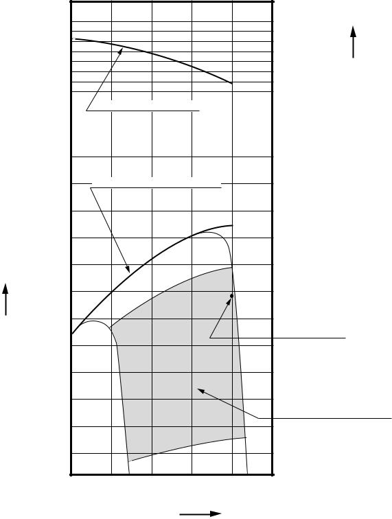
2-4 PERFORMANCE CURVES |
|
|
|
|
||
EH63D |
|
|
|
|
|
|
|
|
|
|
|
|
N-m |
|
|
|
|
|
45 (4.59) |
(kgf-m) |
|
|
|
|
|
|
|
|
|
|
|
|
35 (3.57) |
TORQUE |
|
|
MAXIMUM TORQUE |
|
|||
|
|
|
|
|||
|
15 |
MAXIMUM HORSEPOWER |
|
|
||
|
(20.1) |
|
|
|
|
|
kW |
|
|
|
|
|
|
(HP) |
|
|
|
|
|
|
HORSEPOWER |
10 |
|
|
|
CONTINUOUS |
|
(13.4) |
|
|
|
|||
|
|
|
RATED HP |
|
||
|
|
|
|
|
||
|
|
|
|
|
|
|
|
|
|
|
|
RECOMMENDED |
|
|
|
|
|
|
HORSEPOWER RANGE |
|
|
5 |
|
|
|
|
|
|
(6.7) |
|
|
|
|
|
|
2000 |
2400 |
2800 |
3200 |
3600 |
|
|
|
REVOLUTION |
|
r.p.m |
|
|
|
|
|
|
- 3 - |
|
|

EH64D |
|
|
|
|
|
|
|
|
|
|
|
|
|
|
N-m |
|
|
|
|
|
45 (4.59) |
(kgf-m) |
|
|
|
|
|
|
|
||
|
|
|
|
|
35 |
(3.57) |
TORQUE |
|
|
|
MAXIMUM TORQUE |
|
|||
|
|
MAXIMUM HORSEPOWER |
|
|
|
||
|
15 |
|
|
|
|
|
|
|
(20.1) |
|
|
|
|
|
|
kW |
|
|
|
|
|
|
|
(HP) |
|
|
|
|
|
|
|
|
|
|
|
|
CONTINUOUS |
||
HORSEPOWER |
10 |
|
|
|
RATED HP |
|
|
|
|
|
|
|
|
||
(13.4) |
|
|
|
|
|
|
|
|
|
|
|
RECOMMENDED |
|||
|
|
|
|
HORSEPOWER RANGE |
|||
|
|
|
|
|
|||
|
5 |
|
|
|
|
|
|
|
(6.7) |
|
|
|
|
|
|
|
2000 |
2400 |
2800 |
3200 |
3600 |
|
|
|
|
REVOLUTION |
|
r.p.m |
|
|
|
|
|
|
|
- 4 - |
|
|
|

EH65D |
|
|
|
|
|
|
|
|
|
|
|
|
|
|
N-m |
|
|
|
|
|
|
45 (4.59) |
(kgf-m) |
|
|
|
|
|
|
|
|
|
|
|
|
|
|
35 (3.57) |
TORQUE |
|
|
|
MAXIMUM TORQUE |
|
|||
|
|
MAXIMUM HORSEPOWER |
|
|
|
||
|
15 |
|
|
|
|
|
|
|
(20.1) |
|
|
|
|
|
|
kW |
|
|
|
|
|
|
|
(HP) |
|
|
|
|
|
CONTINUOUS |
|
|
|
|
|
|
|
RATED HP |
|
HORSEPOWER |
10 |
|
|
|
|
|
|
(13.4) |
|
|
|
|
|
|
|
|
|
|
|
|
RECOMMENDED |
||
|
|
|
|
|
HORSEPOWER RANGE |
||
|
|
|
|
|
|
|
|
|
5 |
|
|
|
|
|
|
|
(6.7) |
|
|
|
|
|
|
|
2000 |
2400 |
2800 |
3200 |
3600 |
|
|
|
|
REVOLUTION |
|
|
r.p.m |
|
|
|
|
|
|
- 5 - |
|
|
|
3. FEATURES
The overhead valve arrangement is adopted for ensuring high power, low fuel consumption and low oil consumption.
The adoption of twin-cylinder in the angle of 90 degree (V arrangement) and crankcase in one piece, plastic blower housing etc. offers a compactness and light weight, making the arrangements for installing the engine much easier into many kinds of power equipments.
The forged steel crankshaft and high loading capacity ball bearing offer high durability, and full pressure lubrication system with trochoid type oil pump and large capacity air cleaner with dual elements enhance the reliability.
The effective combustion chamber shape and the precisely tuned intake and exhaust valve system enhance the low exhaust emission and ensure the engine characteristics of high torque at low speed.
The carburetor with fuel cut valve, 12V-15A alternator and pulse type fuel pump are employed as standard features so that the engine can be utilized for many usage.
- 6 -
4. GENERAL DESCRIPTION OF ENGINE COMPONENTS
ROBIN EH63D/ 64D/ 65D series engine is air-cooled, 4-stroke, twin-cylinder, OHV arrangement gasoline engine. The twin-cylinder is located in the angle of 90 degree; #1 cylinder is in the RH side and #2 cylinder in LH side as viewed from flywheel (cooling fan) side.
4-1 CYLINDER AND CRANKCASE
The twin-cylinder and crankcase is single piece aluminum die-casting.
The cylinder liner, made of special cast iron, is molded into the aluminum casting.
The crankcase has a mounting surface on the output shaft side, where the main bearing cover is attached.
Fig. 4-1
4-2 MAIN BEARING COVER
The main bearing cover is an aluminum die-cast- ing, which is mounted on the output shaft side of the crankcase.
Pilots and bosses are machined on the cover for direct mounting of the engine onto such machines as generators and pumps.
It is easy to inspect inside of the engine, after removing the main bearing cover.
Fig. 4-2
4-3 CRANKSHAFT
The crankshaft is forged carbon steel, and the crank pin is induction-hardened.
The output end of the shaft has a crankshaft gear pressed into position.
Engine oil passages are provided onto the journal and pin portions of crankshaft for lubrication.
Fig. 4-3
- 7 -

4-4 CONNECTING ROD AND PISTON
The connecting rod is forged aluminum alloy, and its large and small ends function as bearings.
The piston is an aluminum alloy casting, and carries two compression rings and one oil ring.
Fig. 4-4
4-5 PISTON RINGS
The piston rings are made of special cast iron.
The profile of the top ring is barrel face and the second ring has a tapered face.
The oil ring is designed for better sealing and less oil consumption, in combination with 3 pieces.
1 |
|
|
|
|
|
1 |
TOP |
BARREL |
|
|
RING |
|||
2 |
|
|
||
|
|
|
||
3 |
2 |
SECOND |
TAPER |
|
RING |
||||
|
|
|
||
|
3 |
OIL |
COMBINATION |
|
|
RING |
RING |
||
|
|
|||
|
Fig. 4-5 |
|
|
4-6 CAMSHAFT
The camshaft is made of special cast iron and camshaft gears are casted together in one piece.
Each 2 cam robs are provided for intake and exhaust valves correspondingly.
Both sides of the shaft fit into the plane bearings on the crankcase and main bearing cover.
Fig. 4-6
- 8 -
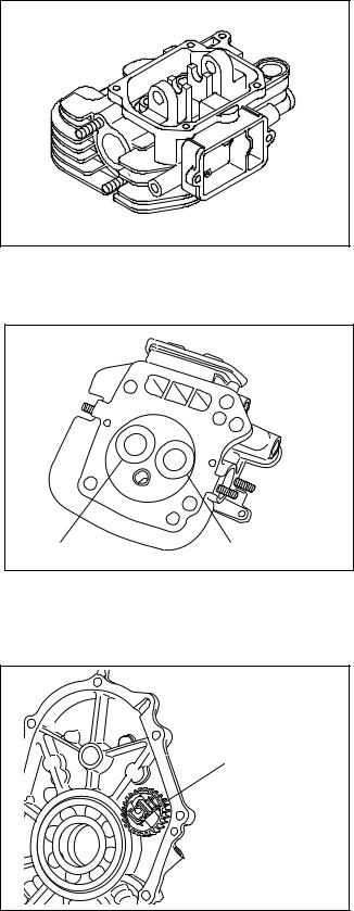
4-7 CYLINDER HEAD
The cylinder head is an aluminum die-casting which utilizes semi-spherical type combustion chamber for the high combustion efficiency.
Fig. 4-7
4-8 VALVE ARRANGEMENT
The intake valve is located on flywheel side of the cylinder head.
The cooling fins and passages design lead cooling air to the exhaust valve area for the optimum cooling.
Hard alloy valve seats are molded in the cylinder head and stellite is fused to the exhaust valve face.
INTAKE VALVE |
EXHAUST VALVE |
Fig. 4-8
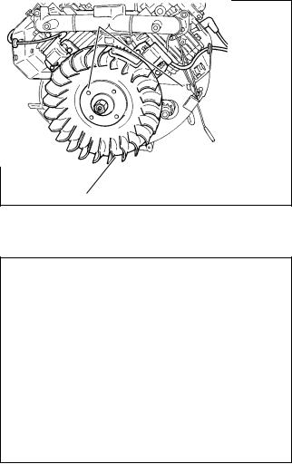
4-9 GOVERNOR SYSTEM
The governor is a centrifugal flyweight type which ensures constant operation at the selected speed
against load variations. GOVERNOR
GEAR
The governor gear with governor weights is installed inside of main bearing cover and driven by the crankshaft.
Fig. 4-9
- 9 -
4-10 COOLING SYSTEM
The large fins on the flywheel provide sufficient cooling air capacity for cylinder and cylinder head.
The cylinder baffle helps the cooling air flow efficiently.
4-11 LUBRICATION SYSTEM
The engine is furnished with full pressure lubrication system.
The trochoid type oil pump is driven by crankshaft and delivers pressurized engine oil through the full-flow type oil filter to the journal and pin portions of crankshaft and camshaft.
4-12 IGNITION SYSTEM
The ignition system is a transistor controlled magneto ignition system which consists of a flywheel and an ignition coil with a built-in transistor installed onto the crankcase.
4-13 CHARGING SYSTEM
Multipolar charging coil is provided inside of flywheel. Charging capacity is 12V-15A.
IGNITION COIL
FLYWHEEL
Fig. 4-10
Fig. 4-11
- 10 -

4-14 CARBURETOR
The engines are equipped with a down draft carburetor that has a float controlled fuel system and a fixed main jet.
The carburetors are calibrated carefully for the sure starting, good acceleration, low fuel consumption and sufficient output.
Fuel cut solenoid valve is provided to prevent engine running on when the key switch is turned to off.
4-15 AIR CLEANER
The air-cleaner is a heavy-duty type with a dual element system; primary side is urethane form (half-wet) and secondary side is dry type.
Fig. 4-12
CLEANER COVER
WING NUT
ELEMENT
URETHANE FOAM
Fig. 4-13
4-16 FUEL PUMP
The engines are equipped with a diaphragm type fuel pump which is operated by the crankcase inside vacuum pressure.
FUEL PUMP
Fig. 4-14
- 11 -

4-17 SECTIONAL VIEW OF ENGINE
CARBURETOR
INTAKE MANIFOLD
IGNITION
P.T.O.SHAFT
OIL
MAIN BEARING COVER
OIL PUMP FILTER
Fig. 4-15
- 12 -
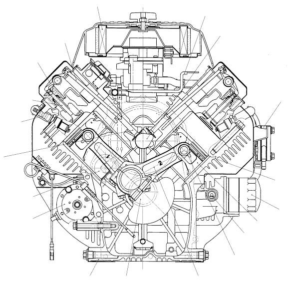
INTAKE |
PUMP |
|
EXHAUST |
||
|
||
SPARK |
|
TAPPET
RING
GOVERNOR
FILTER
ELECTRIC
Fig. 4-16
- 13 -
5. DISASSEMBLY AND REASSEMBLY
5-1 PREPARATIONS AND SUGGESTIONS
When disassembling the engine, memorize the locations of individual parts so that they can be reassembled correctly. If you are uncertain of identifying some parts, it is suggested that tags be attached to them.
Have boxes ready to keep disassembled parts by group.
To prevent losing and misplacing, temporarily assemble each group of disassembled parts.
Carefully handle disassembled parts, and clean them with washing oil if necessary.
Use the correct tools in the correct way.
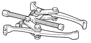
5-2 SPECIAL TOOLS
No Special Tool is needed for disassembling and reassembling the engine.
For pulling off the flywheel, universal type puller being popular in the market place as shown in the illustration is needed.
FLYWHEEL PULLER
Fig. 5-1
- 14 -
5-3 DISASSEMBLY PROCEDURES
Step |
Parts to remove |
Remarks and procedures |
Fasteners |
|
|
|
|
|
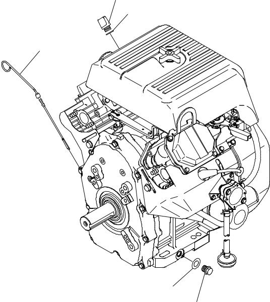
Engine oil drain |
Drain engine oil by removing plugs |
|
1 |
|
located on both side of crankcase. |
|
|
|
|
|
OIL FILLER CAP
GASKET
OIL LEVEL GAUGE
GASKET |
|
STEP 1 |
|
OIL DRAIN PLUG |
|||
|
|||
|
(ON BOTH SIDE) |
||
Fig. 5-2
- 15 -

Step |
Parts to remove |
Remarks and procedures |
Fasteners |
2 |
Air cleaner cover and elements |
Remove breather pipe from #1 |
10-32x11mm ; |
|
cylinder head. |
3 pcs. |
|
|
|
||
3 |
Air cleaner base |
|
|
|
|
|
WING NUT |
|
|
|
CLEANER |
|
|
|
COVER |
BREATHER
PIPE
STEP 2
Fig. 5-4
FLANGE BOLT (Inch) : 3 pcs.
CLEANER
ELEMENT
STEP 3
CLEANER BASE
Fig. 5-3
- 16 -
Step |
Parts to remove |
Remarks and procedures |
Fasteners |
|
4 |
Blower housing |
|
M6x12 ; 8 pcs. |
|
5 |
Chock control lever and link |
|
M6 |
|
|
CHOKE |
LINK PIVOT |
|
|
|
WAVED |
|
|
|
|
CONTROL ROD |
|
|
|
|
|
WASHER |
|
|
|
|
M5 TAPPING |
|
BLOWER HOUSING |
|
|
SCREW : 1 pce. |
|
|
|
|
CLAMP |
|
|
|
|
CHOKE |
|
|
|
|
KNOB |
|
|
|
RETURN |
CHOKE |
|
|
|
CONTROL |
|
|
|
|
SPRING |
|
|
|
|
LINK |
|
|
|
|
|
|
|
|
STEP 5
STEP 4
M6 FLANGE
BOLT : 8 pcs
Fig. 5-5
- 17 -

Step |
Parts to remove |
Remarks and procedures |
Fasteners |
|
|
|
|
|
Carburetor |
At first remove fuel pipe. |
M8x80 ; 2 pcs. |
6 |
|
Take out carburetor along with |
|
|
governor rod and rod spring. |
|
|
|
|
|
|
|
|
|
|
M8 FLANGE
BOLT : 2 pcs.
CARBURETOR |
FUEL PIPE |
Fig. 5-7
GASKET, carburetor
STEP 6
Fig. 5-6
- 18 -
Step |
Parts to remove |
|
Remarks and procedures |
Fasteners |
|
|
|
|
|
|
|
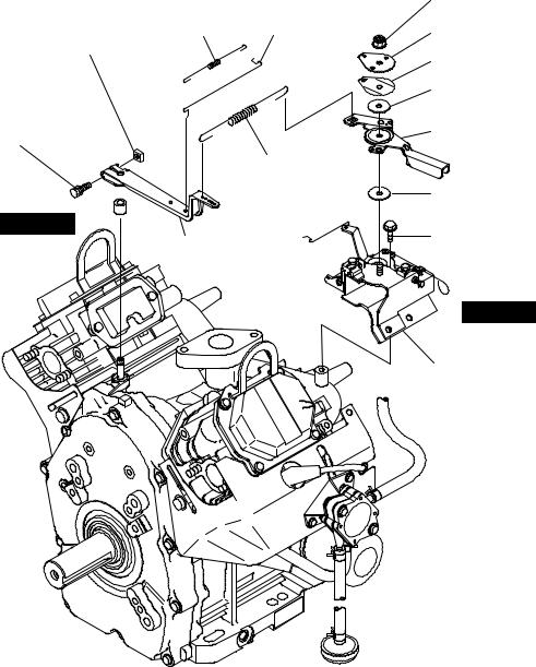
Governor lever ; |
M6X12 ; 3 pcs |
|
|
|
Remove bolt and take out lever. |
M6 self-lock nut |
|
|
|
Speed control lever ; |
|
|
7 |
Governor lever and |
1. Governor spring |
|
|
Speed control lever |
2. Self lock nut |
|
||
|
|
|||
|
|
3. |
Stop plate |
|
|
|
4. |
Spring washer |
|
|
|
5. |
Speed control lever |
|
|
|
|
|
|
8 |
Speed control bracket unit |
|
|
M6X12 ; 3 pcs |
|
|
|
|
|
M6 NUT : 1 pce.
M6 BOLT
AND WASHER : 1 pce.
STEP 7
ROD
SPRING
GOVERNOR LEVER
|
M6 SELF LOCK |
GOVERNOR |
NUT : 1 pce. |
|
|
ROD |
STOP PLATE |
|
|
|
SPRING WASHER |
|
FRICTION |
|
WASHER |
|
SPEED CONTROL |
|
LEVER |
GOVERNOR |
|
SPRING |
FRICTION |
|
|
|
WASHER |
|
M6 FLANGE |
|
BOLT : 3 pcs. |
STEP 8
BRACKET UNIT, speed control
Fig. 5-8
- 19 -
 Loading...