


PARTS MANUAL
Models
EH025
ENGINE
PUB-EP5792
Rev. 03/03

940 Lively Blvd. • Wood Dale, IL 60191 • Phone: 630-350-8200 • Fax: 630-350-8212
e-mail: sales@robinamerica.com • www.robinamerica.com |
© Copyright 2003 Robin America, Inc. |
HOW TO USE THIS MANUAL
Robin engines are identified by MODEL, SPECIFICATION, and CODE NUMBER. For each model there may be many different versions called specifications. Each specification will be unique in some way. The difference may only be the paint color or it may have a different type of PTO or some other significant difference.
In order the identify the correct service part number, it is important to confirm the specification and code numbers for your engine. The specification and code number together are know as the PRODUCT NUMBER.
All Robin 4 cycle engines have a Product Number label similar to the label illustrated below.
The Product Number Label has a 15 digit alphanumeric string that consists of the SPECIFICATION (SPEC) number (11 digits) and the CODE number (4 digits). Please note the illustration below:
E H 0 2 5 


 X X X X
SPEC NO. (11 digits) |
CODE NO. (4 digits) |
||
|
|
|
|
|
|
|
|
PRODUCT NO. (15 digits)
EH025 |
- 3 - |
03-03 |
MANUAL LAYOUT
1 |
4 |
|
|
2 |
3 |
|
|
1 |
6 |
7 |
9 |
2 |
|
|
|
|
|
|
|
|
|
3 |
|
|
|
|
|
|
5 |
|
|
|
|
|
|
4 |
|
|
|
8 |
|
|
|
|
|
|
|
|
1. |
SECTION NAME |
Parts are broadly classified according to their functions. |
|
|
|
|
|
|
Refer to the Group Index (table of contents) for respective section name. |
|
|
||
2. |
FIG. No. |
The FIG. number indexes the reference and part numbers to the illustration. Figure numbers |
||||
|
|
that vary only in the tens place (i.e..: 700 and 710) are in a group of the same section |
||||
|
|
(i.e..:Electrical Device Group). |
|
|
|
|
3. |
REF. No . |
The Reference number identifies the part illustration with the corresponding part number in the |
||||
|
|
part list. |
|
|
|
|
4. |
SUBASSEMBLY |
SUBASSEMBLY parts of part assembly are listed below the assembly part. The subassembly |
||||
|
|
part reference number is indicated by the number led by "-" such as "-1", "-2". |
|
|
||
5. |
PART NUMBER |
It is the number assigned for sales unit. Use the PART No. when making an order. |
|
|
||
6. |
DESCRIPTION |
It is designation of the part. |
|
|
|
|
7. |
QTY. |
Quantity of each part used for each product. |
|
|
|
|
8. |
REMARKS |
This gives a distinctive feature and/or a supplementary comment for the type, the specification, |
||||
|
|
and the part concerned. It also shows part number(s) interchangeable for the part. |
||||
9. |
FROM-TO |
This section shows the CODE No. to indicate the history of progress in which improved parts |
||||
|
|
have been introduced in the product. The FROM-TO CODE No. helps to identify PART No. |
||||
|
|
being employed in the product concerned. See the examples below: |
|
|
||
-The part is used in the product irrespective of CODE No.
2101- |
|
The part is used in the products with CODE No. of 2101 and after this number. |
- |
2100 |
The part is used in the products with CODE No. of 2100 and before this number. |
EH025 |
- 4 - |
03-03 |

GROUP INDEX |
|
Group Name |
Page |
CRANKCASE GROUP............................................................................... |
6 |
CRANKSHAFT, PISTON GROUP .............................................................. |
8 |
INTAKE and EXHAUST GROUP.............................................................. |
10 |
COOLING and STARTING GROUP......................................................... |
12 |
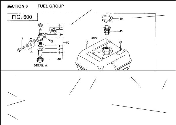
FUEL, LUBRICANT GROUP.................................................................... |
14 |
ELECTRIC DEVICE GROUP ................................................................... |
16 |
CLUTCH GROUP .................................................................................... |
18 |
ACCESSORY GROUP............................................................................. |
20 |
INDEX OF DESCRIPTION SYMBOLS
SYMBOL |
DESCRIPTION |
AY ........................... |
ASSEMBLY |
CP........................... |
COMPLETE |
EX........................... |
EXPORT (from Japan) |
FIG.......................... |
FIGURE |
FR........................... |
FRONT |
" .............................. |
INCH |
INCL. ...................... |
INCLUDE |
~L............................ |
LITER |
L= ........................... |
LENGTH (in. mm) |
L.H. (LH)................. |
LEFT-HAND SIDE |
MECH..................... |
MECHANICAL |
NO (NON)............... |
NONE |
OPT......................... |
OPTIONAL |
O.S. ........................ |
OVER SIZE |
SYMBOL |
DESCRIPTION |
P= ........................... |
PITCH (in mm) |
P.T.O. (PTO) ........... |
POWER TAKE OFF |
REF......................... |
REFERENCE |
R.H. (RH)................ |
RIGHT HAND SIDE |
RR. ......................... |
REAR |
STD. ....................... |
STANDARD |
SW.......................... |
SWITCH |
T= ........................... |
THICKNESS (in mm) |
UN .......................... |
UNIT |
U.S.......................... |
UNDER SIZE |
~V ........................... |
VOLTAGE |
~W .......................... |
WATT |
W/ ........................... |
WITH |
W/O ........................ |
WITHOUT |
EH025 |
- 5 - |
03-03 |

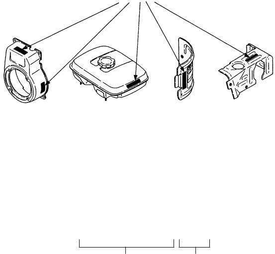
SECTION 1 CRANKCASE GROUP
FIG. 100
EH025 |
- 6 - |
03-03 |
SECTION 1 |
CRANKCASE GROUP |
|
|
|||
|
|
|
|
|
|
|
REF. |
PART NO. |
DESCRIPTION |
QTY. |
REMARKS |
FROM-TO |
FIG. |
10 |
592-10050-01 |
CYLINDER BLOCK |
1 |
|
|
100 |
95 |
011-90595-10 |
SOCKET HEAD BOLT |
6 |
|
|
100 |
96 |
011-90595-00 |
SOCKET HEAD BOLT |
2 |
|
|
100 |
270 |
592-65006-00 |
OIL GAUGE |
1 |
|
|
100 |
280 |
021-31600-20 |
GASKET |
1 |
|
|
100 |
410 |
592-65000-00 |
CASE, OIL |
1 |
|
|
100 |
415 |
592-65001-00 |
GASKET, CASE |
1 |
|
|
100 |
416 |
004-36051-80 |
SCREW AY |
4 |
|
|
100 |
628 |
591-15012-00 |
BALL |
2 |
|
|
100 |
665 |
592-15014-00 |
SPACER |
2 |
|
|
100 |
680 |
592-10040-00 |
ROCKER COVER CP |
1 |
|
|
100 |
685 |
592-15011-00 |
RETAINER PLATE |
1 |
|
|
100 |
686 |
592-15010-00 |
LEAD VALVE |
1 |
|
|
100 |
687 |
011-90499-80 |
SOCKET HEAD BOLT |
1 |
|
|
100 |
690 |
592-15008-00 |
GASKER, ROCKER COVER |
1 |
|
|
100 |
710 |
004-36051-60 |
SCREW AND WASHER |
3 |
|
|
100 |
810 |
592-15005-02 |
COVER, CAMGEAR |
1 |
|
|
100 |
830 |
592-15007-00 |
GASKET, CAMGEAR COVER |
1 |
|
|
100 |
850 |
592-15009-00 |
BREATHER PIPE |
1 |
|
|
100 |
851 |
056-10800-10 |
HOSE CLAMP |
1 |
|
|
100 |
860 |
004-36051-40 |
SCREW AND WASHER |
3 |
|
|
100 |
870 |
592-65002-00 |
OIL TUBE |
1 |
|
|
100 |
875 |
592-65003-00 |
OIL WEIGHT |
1 |
|
|
100 |
|
|
|
|
|
|
|
|
|
|
|
|
|
|
|
|
|
|
|
|
|
|
|
|
|
|
|
|
|
|
|
|
|
|
|
|
|
|
|
|
|
|
|
|
|
|
|
|
|
|
|
|
|
|
|
|
|
|
|
|
|
|
|
|
|
|
|
|
|
|
|
|
|
|
|
|
|
|
|
|
|
|
|
|
|
|
|
|
|
|
|
|
|
|
|
|
|
|
|
|
|
|
|
|
|
|
|
|
|
|
|
|
|
|
|
|
|
|
|
|
|
|
|
|
|
|
|
|
|
|
|
|
|
|
|
|
|
|
|
|
|
|
|
|
|
|
|
|
|
|
|
|
|
|
|
|
|
|
|
|
|
|
|
|
|
|
|
|
EH025 |
- 7 - |
03-03 |
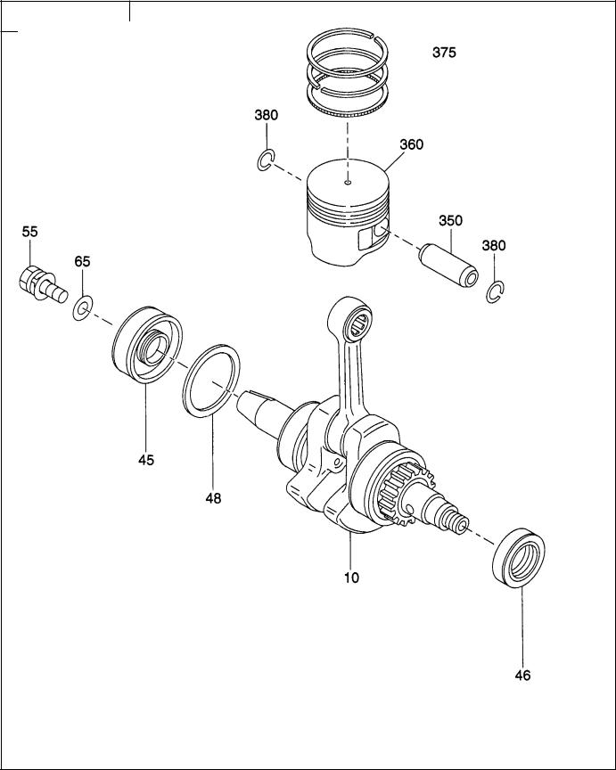
SECTION 2 CRANKSHAFT, PISTON GROUP
FIG. 200
EH025 |
- 8 - |
03-03 |
 Loading...