


User's Guide
Hammerfall® DSP System
HDSPe RayDAT
TotalMix™
24 Bit / 192 kHz 9
SyncAlign® |
ZLM® |
SyncCheck® |
SteadyClock™
PCI Express Digital I/O Card
2 + 2 + 32 Channels AES / SPDIF / ADAT Interface
24 Bit / 192 kHz Digital Audio
72 x 36 Matrix Router
2 x MIDI I/O Quick Boot

General
1 |
Introduction ............................................................... |
6 |
2 |
Package Contents ..................................................... |
6 |
3 |
System Requirements .............................................. |
6 |
4 |
Brief Description and Characteristics..................... |
6 |
5 |
Hardware Installation................................................ |
7 |
6 |
Hardware – Connectors |
|
6.1 |
External Connectors .............................................. |
7 |
6.2 |
Internal Connectors................................................ |
8 |
7 |
Accessories ............................................................... |
9 |
8 |
Warranty..................................................................... |
9 |
9 |
Appendix .................................................................... |
9 |
Driver Installation and Operation - Windows
10 |
Driver and Firmware |
|
|
|
10.1 |
Driver Installation ................................................. |
12 |
|
10.2 |
Driver Update ....................................................... |
12 |
|
10.3 |
De-Installing the Drivers....................................... |
13 |
|
10.4 |
Firmware Update.................................................. |
13 |
11 Configuring the HDSPe RayDAT |
|
|
11.1 |
Settings Dialog ..................................................... |
14 |
11.2 |
Settings Dialog – DDS.......................................... |
16 |
11.3 |
Clock Modes – Synchronization........................... |
17 |
12 Operation and Usage |
|
|
12.1 |
Playback............................................................... |
19 |
12.2 |
DVD Playback (AC-3 / DTS) ................................ |
20 |
12.3 |
Notes on WDM ..................................................... |
21 |
12.4 |
Channel Count under WDM ................................. |
21 |
12.5 |
Multi-client Operation ........................................... |
22 |
12.6 |
Digital Recording .................................................. |
23 |
13 |
Operation under ASIO |
|
|
|
13.1 |
General ................................................................ |
24 |
|
13.2 |
Channel Count under ASIO ................................. |
24 |
|
13.3 |
Known Problems .................................................. |
25 |
14 |
Operation under GSIF............................................. |
25 |
|
15 |
Using more than one HDSPe RayDAT .................. |
26 |
|
16 |
DIGICheck ................................................................ |
26 |
|
17 |
Hotline – Troubleshooting |
|
|
|
17.1 |
General ................................................................ |
27 |
|
17.2 |
Installation ............................................................ |
28 |
2 |
User's Guide HDSPe RayDAT © RME |

Driver Installation and Operation - Mac OS X
18 |
Driver and Flash Update |
|
|
|
18.1 |
Driver Installation ................................................. |
30 |
|
18.2 |
Driver Update....................................................... |
30 |
|
18.3 |
Flash Update........................................................ |
30 |
19 |
Configuring the HDSPe RayDAT |
|
|
|
19.1 |
Settings Dialog..................................................... |
31 |
|
19.2 |
Settings Dialog – DDS ......................................... |
32 |
|
19.3 |
Clock Modes – Synchronization .......................... |
34 |
20 |
Mac OS X FAQ |
|
|
|
20.1 |
Round about Driver Installation ........................... |
35 |
|
20.2 |
Repairing Disk Permissions................................. |
35 |
|
20.3 |
MIDI doesn't work ................................................ |
35 |
|
20.4 |
Various Information.............................................. |
36 |
|
20.5 |
Supported Sample Rates..................................... |
36 |
|
20.6 |
Channel Count under Core Audio ....................... |
36 |
21 |
Hotline – Troubleshooting ..................................... |
37 |
|
Connections and TotalMix
22 Digital Connections |
|
|
22.1 |
ADAT ................................................................... |
40 |
22.2 |
AES/EBU ............................................................. |
40 |
22.3 |
SPDIF .................................................................. |
41 |
22.4 |
Word Clock .......................................................... |
42 |
22.5 |
MIDI ..................................................................... |
42 |
23 |
Word Clock |
|
|
|
23.1 |
Technical Description and Background............... |
43 |
|
23.2 |
Cables and Termination....................................... |
43 |
|
23.3 |
General Operation ............................................... |
44 |
24 |
TotalMix: Routing and Monitoring |
|
|
|
24.1 |
Overview .............................................................. |
45 |
|
24.2 |
The User Interface ............................................... |
47 |
|
24.3 |
Elements of a Channel ........................................ |
48 |
|
24.4 |
Tour de TotalMix.................................................. |
48 |
|
24.5 |
Submix View ........................................................ |
50 |
|
24.6 |
Mute and Solo...................................................... |
50 |
|
24.7 |
Quick Access Panel............................................. |
51 |
|
24.8 |
Presets................................................................. |
51 |
|
24.9 |
Monitor Panel....................................................... |
53 |
|
24.10 |
Preferences.......................................................... |
53 |
|
24.11 |
Editing the Names ............................................... |
54 |
|
24.12 |
Hotkeys ................................................................ |
55 |
|
24.13 |
Menu Options....................................................... |
56 |
|
24.14 |
Level Meter .......................................................... |
57 |
User's Guide HDSPe RayDAT © RME |
3 |

25 |
TotalMix: The Matrix |
|
|
|
25.1 |
Overview .............................................................. |
58 |
|
25.2 |
Elements of the Matrix View ................................ |
58 |
|
25.3 |
Usage................................................................... |
58 |
|
25.4 |
Advantages of the Matrix ..................................... |
59 |
26 |
TotalMix Super-Features |
|
|
|
26.1 |
ASIO Direct Monitoring (Windows only) .............. |
59 |
|
26.2 |
Selection and Group based Operation ................ |
60 |
|
26.3 |
Copy Routings to other Channels........................ |
60 |
|
26.4 |
Delete Routings.................................................... |
60 |
|
26.5 |
Recording a Subgroup (Loopback)...................... |
61 |
|
26.6 |
Using external Effects Devices ............................ |
62 |
|
26.7 |
MS Processing ..................................................... |
63 |
27 |
TotalMix MIDI Remote Control |
|
|
|
27.1 |
Overview .............................................................. |
64 |
|
27.2 |
Mapping ............................................................... |
64 |
|
27.3 |
Setup.................................................................... |
65 |
|
27.4 |
Operation ............................................................. |
65 |
|
27.5 |
Simple MIDI Control............................................. |
66 |
|
27.6 |
Loopback Detection ............................................. |
67 |
Technical Reference
28 |
Tech Info .................................................................. |
70 |
|
29 |
Technical Specifications |
|
|
|
29.1 |
Digital Inputs ........................................................ |
71 |
|
29.2 |
Digital Outputs...................................................... |
72 |
|
29.3 |
Digital ................................................................... |
72 |
|
29.4 |
MIDI...................................................................... |
72 |
30 |
Technical Background |
|
|
|
30.1 |
Lock and SyncCheck ........................................... |
73 |
|
30.2 |
Latency and Monitoring........................................ |
74 |
|
30.3 |
DS – Double Speed ............................................. |
75 |
|
30.4 |
QS – Quad Speed................................................ |
75 |
|
30.5 |
AES/EBU – SPDIF ............................................... |
76 |
|
30.6 |
SteadyClock ......................................................... |
77 |
|
30.7 |
Terminology ......................................................... |
78 |
4 |
User's Guide HDSPe RayDAT © RME |

User's Guide
HDSPe RayDAT
General
User's Guide HDSPe RayDAT © RME |
5 |

1. Introduction
Thank you for choosing the RME Hammerfall DSP system. This unique audio system is capable of transferring digital audio data directly to a computer from practically any device. The latest Plug and Play technology guarantees a simple installation, even for the inexperienced user. The numerous unique features and well thought-out configuration dialog puts the Hammerfall DSP at the very top of the range of computer-based audio interfaces.
The package contains drivers for Windows XP / Vista / 7 and Mac OS X x86 (Intel).
RME's high-performance philosophy guarantees maximum system performance by executing as many functions as possible not in the driver (i.e. the CPU), but directly within the audio hardware.
2. Package Contents
Please check your HDSPe RayDAT package to include each of the following:
•HDSPe RayDAT PCI Express card
•HDSPe RayDAT expansion board
•Quick Info guide
•RME Driver CD
•Digital breakout cable (XLR / phono)
•MIDI breakout cable
•Internal cable (3-pin)
•Flat ribbon cable (14-pin)
•2 optical cable (TOSLINK), 2 m (6.6 ft)
3. System Requirements
•Windows XP or higher, Mac OS X Intel (10.4.8 or higher)
•PCI Express Interface: one free PCI Express slot, 1 lane, version 1.1
4. Brief Description and Characteristics
•All settings can be changed in real-time
•AES and SPDIF I/Os can be used simultaneously
•8 buffer sizes/latencies available: 0.7 / 1.5 / 3 / 6 / 12 / 23 / 46 / 93 ms
•16 channels 96 kHz/24 bit record/playback via ADAT optical (S/MUX)
•8 channels 192 kHz/24 bit record/playback via ADAT optical (S/MUX4)
•Automatic and intelligent master/slave clock control
•Unsurpassed Bitclock PLL (audio synchronization) in ADAT mode
•TotalMix for latency-free submixes and perfect ASIO Direct Monitoring
•SyncAlign guarantees sample aligned and never swapping channels
•SyncCheck tests and reports the synchronization status of input signals
•2 x MIDI I/O, 16 channels high-speed MIDI
•DIGICheck DSP: Level meter in hardware, peakand RMS calculation
•TotalMix: 2592 channel mixer with 42 bit internal resolution
•SteadyClock: Jitter-immune, super-stable digital clock
•Quick Boot technology for immediate loading of the hardware settings
•Optional Time Code module (TCO) for external Video-/SMPTE synchronization
6 |
User's Guide HDSPe RayDAT © RME |
5. Hardware Installation
Before installing the PCI Express card, please make sure the computer is switched off and the power cable is disconnected from mains supply. Inserting or removing the card while the computer is in operation can cause irreparable damage to both motherboard and card!
1.Disconnect the power cord and all other cables from the computer.
2.Remove the computer's housing. Further information on how to do this can be obtained from your computer’s instruction manual.
3.Important: Before removing the HDSPe RayDAT from its protective bag, discharge any static in your body by touching the metal chassis of the PC.
4.Prior to installation: Connect the HDSPe RayDAT card to the Expansion Board using the supplied flat ribbon cable.
5.Insert the HDSPe RayDAT firmly into a free PCI Express slot, press and fasten the screw.
6.Insert the Expansion Board and fasten the screw.
7.Replace the computer's housing.
8.Reconnect all cables including the power cord.
6. Hardware - Connectors
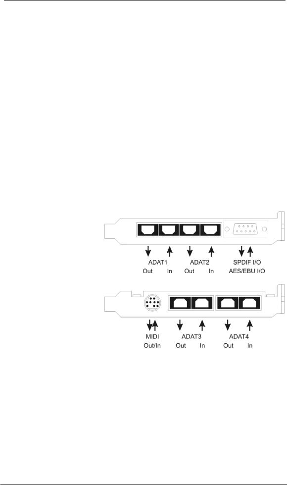
6.1 External Connectors
HDSPe RayDAT consists of the main PCIe board and an Expansion Board. All the essential electronics are located on the PCI card, so it will also work without the Expansion Board.
The main board's bracket has two ADAT optical inputs and outputs, as well as a 9-pin D- sub socket. AES/EBU and coaxial SPDIF input and output are provided via the included breakout cable, whereby the red phono socket is the output.
The Expansion Board's bracket gives access to a third and fourth ADAT optical input and output.
ADAT4 can also be used as optical SPDIF I/O, if set up accordingly in the Settings dialog.
The included MIDI breakout cable is connected to the 9-pin Mini-DIN connector, providing two MIDI inputs and outputs.
Note: If neither MIDI I/O nor a third and fourth ADAT I/O are required, it is not necessary to install the Expansion Board at all.
User's Guide HDSPe RayDAT © RME |
7 |

6.2 Internal Connectors
AEB1 IN / CD IN
This internal digital input can be used with both SPDIF and ADAT format.
SPDIF
•Connection to an internal CD-ROM drive with digital audio output. Allows for a direct transfer of digital audio data within the computer.
•Connection to SPDIF output of another card. This internal SPDIF connection can be used to synchronize multiple cards with sample accuracy, and without the need for an external connection. Please note that the external SPDIF input can no longer be used.
ADAT
•Connection of a TEB (TDIF Expansion Board). The highest sample rate is 96 kHz, the 4- channel Double Wire mode (S/MUX) is automatically activated in Double Speed mode. Select AEB / TEB ADAT1 In in the Settings dialog.
•Connection of an AEB4-I or AEB8-I. When using these (no longer available) Expansion Boards ST7 (X507) must also be connected to the Expansion Board. The highest sample rate is 48 kHz. Select AEB /TEB ADAT1 In in the Settings dialog.
SPDIF OUT (X502)
Internal SPDIF output, operates in parallel to the coaxial output.
AEB2 IN
Connection of a second AEBx-I or TEB. Please note the label GND for correct polarity. Select AEB / TEB ADAT2 In in the Settings dialog. In this configuration the optical input ADAT2 can not be used anymore.
ADAT 1 OUT
This internal ADAT output carries the same audio data as the optical output ADAT1. Connecting an AEB4-O or AEB8-O, the highest sample rate is 48 kHz. Connecting a TEB the highest sample rate is 96 kHz, the 4-channel Double Wire mode (S/MUX) is automatically activated. Please note the label GND for correct polarity.
ADAT 2 OUT
This internal ADAT output carries the same audio data as the optical output ADAT2. See ADAT1 OUT for details. Both ports can be used to operate one AEBx-O each, for a maximum of 16 analog outputs.
SYNC IN
Internal word clock input for synchronization of multiple cards via SYNC OUT.
SYNC OUT
This 3-pin connector carries an internal word clock signal. It can be used to synchronize multiple cards with sample accuracy, and without the need for an external connection. The card where SYNC OUT is used is Master, the one with SYNC IN is Slave. In the Settings dialog the Slave has to be set to Sync In under Pref. Sync Ref, the Clock Mode must be set to AutoSync.
WCM / TCO (X403)
10-pin connector to connect the optional 9632 Word Clock Module or the optional Time Code Option (TCO) via flat ribbon cable.
X402
14-pin connector to connect the Expansion Board using flat ribbon cable.
8 |
User's Guide HDSPe RayDAT © RME |

7. Accessories
RME offers several optional accessories. Also parts of the HDSPe RayDAT are available separately.
Part Number |
Description |
36003 |
Optical cable, TOSLINK, 0.5 m (1.6 ft) |
36004 |
Optical cable, TOSLINK, 1 m (3.3 ft) |
36006 |
Optical cable, TOSLINK, 2 m (6.6 ft) |
36007 |
Optical cable, TOSLINK, 3 m (9.9 ft) |
36008 |
Optical cable, TOSLINK, 5 m (16.4 ft) |
36009 |
Optical cable, TOSLINK, 10 m (33 ft) |
Standard lightpipe with TOSLINK connectors, RME approved quality.
BO968 |
Breakout cable SPDIF/AES |
BOHDSP9652 |
Breakout cable MIDI |
VKHDSP9652 |
Internal flat cable 14-pin |
WCM9632 |
Word clock Expansion Board |
TCOHDSP |
Time Code Option HDSPe series |
TEB |
TDIF Expansion Board |
8. Warranty
Each individual HDSPe undergoes comprehensive quality control and a complete test at IMM before shipping. The usage of high grade components allows us to offer a full two year warranty. We accept a copy of the sales receipt as valid warranty legitimation.
If you suspect that your product is faulty, please contact your local retailer. The warranty does not cover damage caused by improper installation or maltreatment - replacement or repair in such cases can only be carried out at the owner’s expense.
RME does not accept claims for damages of any kind, especially consequential damage. Liability is limited to the value of the Hammerfall DSP. The general terms of business drawn up by Audio AG apply at all times.
9. Appendix
RME news, driver updates and further product information are available on our website:
http://www.rme-audio.de
Distributor: Audio AG, Am Pfanderling 60, D-85778 Haimhausen, Tel.: (49) 08133 / 91810
Manufacturer: IMM Elektronik GmbH, Leipziger Strasse 32, D-09648 Mittweida
Trademarks
All trademarks, registered or otherwise, are the property of their respective owners. RME, DIGICheck and Hammerfall are registered trademarks of RME Intelligent Audio Solutions. DIGI96, SyncAlign, ZLM, SyncCheck, Hammerfall DSP, HDSPe RayDAT, SteadyClock, TMS and TotalMix are trademarks of RME Intelligent Audio Solutions. Alesis and ADAT are registered trademarks of Alesis Corp. ADAT optical is a trademark of Alesis Corp. Microsoft, Windows 2000 and Windows XP are registered trademarks or trademarks of Microsoft Corp. Steinberg, Cubase and VST are registered trademarks of Steinberg Media Technologies GmbH. ASIO is a trademark of Steinberg Media Technologies GmbH.
Copyright © Matthias Carstens, 03/2010. Version 1.3
Current driver version: Windows: 3.083, Mac OS X: 2.71. Firmware 11
User's Guide HDSPe RayDAT © RME |
9 |

Although the contents of this User’s Guide have been thoroughly checked for errors, RME can not guarantee that it is correct throughout. RME does not accept responsibility for any misleading or incorrect information within this guide. Lending or copying any part of the guide or the RME Driver CD, or any commercial exploitation of these media without express written permission from RME Intelligent Audio Solutions is prohibited. RME reserves the right to change specifications at any time without notice.
CE / FCC Compliance
CE
This device has been tested and found to comply with the limits of the European Council Directive on the approximation of the laws of the member states relating to electromagnetic compatibility according to RL89/336/EWG and RL73/23/EWG.
FCC
This equipment has been tested and found to comply with the limits for a Class B digital device, pursuant to Part 15 of the FCC Rules. These limits are designed to provide reasonable protection against harmful interference in a residential installation. This equipment generates, uses, and can radiate radio frequency energy and, if not installed and used in accordance with the instructions, may cause harmful interference to radio communications. However, there is no guarantee that interference will not occur in a particular installation. If this equipment does cause harmful interference to radio or television reception, which can be determined by turning the equipment off and on, the user is encouraged to try to correct the interference by one or more of the following measures:
-Reorient or relocate the receiving antenna.
-Increase the separation between the equipment and receiver.
-Connect the equipment into an outlet on a circuit different from that to which the receiver is connected.
-Consult the dealer or an experienced radio/TV technician for help.
RoHS
This product has been soldered lead-free and fulfils the requirements of the RoHS directive.
ISO 9001
This product has been manufactured under ISO 9001 quality management. The manufacturer, IMM Elektronik GmbH, is also certified for ISO 14001 (Environment) and ISO 13485 (medical devices).
Note on Disposal
According to the guide line RL2002/96/EG (WEEE – Directive on Waste Electrical and Electronic Equipment), valid for all european countries, this product has to be recycled at the end of its lifetime.
In case a disposal of electronic waste is not possible, the recycling can also be done by IMM Elektronik GmbH, the manufacturer of the HDSPe RayDAT.
For this the device has to be sent free to the door to:
IMM Elektronik GmbH
Leipziger Straße 32
D-09648 Mittweida
Germany
Shipments not prepaid will be rejected and returned on the original sender's costs.
10 |
User's Guide HDSPe RayDAT © RME |
User's Guide
HDSPe RayDAT
Driver Installation and Operation - Windows
User's Guide HDSPe RayDAT © RME |
11 |

10. Driver and Firmware
10.1 Driver Installation
After the HDSPe RayDAT has been installed correctly (see 5. Hardware Installation), and the computer has been switched on, Windows will recognize the new hardware component and start its ‘Hardware Wizard’. Insert the RME Driver CD into your CD-ROM drive, and follow further instructions which appear on your computer screen. The driver files are located in the directory \WDM on the RME Driver CD.
Windows will install the Hammerfall DSP System driver, and will register the card in the system as a new audio device. After a reboot the HDSPe RayDAT is ready for use.
In case the warning messages 'Digital signature not found', 'Do not install driver', 'not certified driver' or similar come up: simply ignore them and continue with the installation.
In case the Hardware Wizard does not show up automatically after installation of the card, do not attempt to install the drivers manually! An installation of drivers for non-recognized hardware will cause a blue screen when booting Windows!
In Windows 7 Microsoft removed the automatic start of the Driver Software Update dialog. Therefore this dialog has to be started manually after the failed driver installation. Hit the Win key, type 'Device Manager', start the Device Manager by selecting it from the list and hit Enter.
The device is shown with a yellow warning symbol. Usually it is already found in the correct category, Sound, Video and Game Controller (Plug & Play detects a multimedia device). Right click on the device and select 'Update Driver Software' from the context menu.
The dialog Update Driver Software appears. Now follow the instructions given below.
10.2 Driver Update
When facing problems with the automatic driver update, the user-driven way of driver installation will work.
Under >Control Panel /System /Device Manager /Sound, Video and Game Controllers /RME HDSPe AES /Properties /Driver< you'll find the 'Update Driver' button.
XP: Select 'Install from a list or specific location (advanced)', click 'Next', select 'Don't search I will choose the driver to install', click 'Next', then 'Have Disk'. Now point to the driver update's directory.
Vista/7: Select 'Browse my computer for driver software', then 'Let me pick from a list of device drivers from my computer', then 'Have Disk'. Now point to the driver update's directory.
This method also allows for the installation of older drivers than the currently installed ones.
12 |
User's Guide HDSPe RayDAT © RME |

10.3 De-Installing the Drivers
A de-installation of the HDSP driver files is not necessary – and not supported by Windows anyway. Thanks to full Plug & Play support, the driver files will not be loaded after the hardware has been removed. If desired these files can then be deleted manually.
Unfortunately Windows Plug & Play methods do not cover the additional autorun entries of TotalMix, the Settings dialog, and the registration of the ASIO driver. Those entries can be removed from the registry through a software de-installation request. This request can be found (like all de-installation entries) in Control Panel, Software. Click on the entry 'RME Hammerfall DSP (WDM)'.
10.4 Firmware Update
The Flash Update Tool updates HDSPe RayDAT to the latest version. It requires an already installed driver.
Start the program pcie_fut.exe. The Flash Update Tool displays the current revision of the HDSPe RayDAT, and whether it needs an update or not. If so, then please press the 'Update' button. A progress bar will indicate when the flash process is finished. The bar moves slowly first (program), then faster (verify).
If more than one interface card is installed, all cards can be flashed by changing to the next tab and repeating the process.
After the update the PCI Express card needs to be reset. This is done by powering down and shutting off the PC. A warm boot is not enough!
When the update fails (status: failure), the card's second BIOS will be used from the next cold boot on (Secure BIOS Technology). Therefore the card stays fully functional. The flash process should then be tried again on a different computer.
Note: Because of the changed hardware revision, Windows might start the hardware assistant and wants to install new drivers. Do NOT let Windows search for new drivers, but follow the instructions given in chapter 10.2.
User's Guide HDSPe RayDAT © RME |
13 |

11. Configuring the HDSPe RayDAT
11.1 Settings Dialog
Configuration of the HDSPe RayDAT is done via its own settings dialog. The panel 'Settings' can be opened:
• by clicking on the hammer symbol in the Task Bar's system tray
The mixer of the Hammerfall DSP system (TotalMix) can be opened:
• by clicking on the mixer icon in the Task Bar's system tray
The hardware of the HDSP system offers a number of helpful, well thought-of practical functions and options which affect how the card operates - it can be configured to suit many different requirements. The following is available in the 'Settings' dialog:
•Input selection
•Configuration of digital I/Os
•Synchronization behaviour
•State of input and output
•Current sample rate
•Latency
Any changes made in the Settings dialog are applied immediately - confirmation (e.g. by clicking on OK or exiting the dialog) is not required. However, settings should not be changed during playback or record if it can be avoided, as this can cause unwanted noises. Also, please note that even in 'Stop' mode, several programs keep the recording and playback devices open, which means that any new settings might not be applied immediately.
The status display at the bottom of the dialog box gives precise information about the current status of the system (Master/Slave, sample rate), and the status of all digital input signals.
Quick Boot
All the card's settings described below are stored in a hardware memory, and are loaded immediately after a power-on of the computer. In clock mode Master even the last used sample rate is set. Directly after switching on the computer, a stable and predictable clock state is found at the HDSPe RayDAT's outputs. This advanced technology completely eliminates disturbing noises and clock network problems during power-up or reboot.
WDM Devices
Not before Vista the OS had been capable to handle more than 32 WDM stereo devices. Therefore under W2k/XP it often makes sense to intentionally limit their number. Otherwise channels or MIDI ports might vanish from the system.
AEB / TEB
ADAT1 In switches the input ADAT1 from the optical connector to the internal connector AEB 1 In / CD In. Here an Expansion Board (AEB4-I, AEB8-I, TEB) can be connected.
ADAT2 In switches the input ADAT2 from the optical connector to the internal connector AEB2 In. Here an Expansion Board (AEB4-I, AEB8-I, TEB) can be connected.
14 |
User's Guide HDSPe RayDAT © RME |
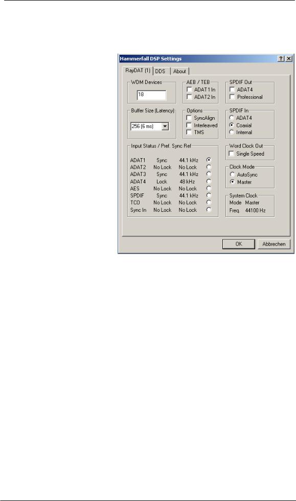
SPDIF Out
The SPDIF output signal is constantly available at the phono plug. After selecting 'ADAT4' it is also routed to the optical TOSLINK output ADAT4. For further details about the setting ‘Professional’ please refer to chapter 22.2.
Buffer Size
The setting Buffer Size determines the latency between incoming and outgoing ASIO and GSIF data, as well as affecting system stability (see chapter 13/14). GSIF and WDM can be set from 32 to 512 samples. Above 512, only ASIO is affected.
Options
SyncAlign guarantees synchronous channels when using WDM multi-track software. This option should only be switched off in case the used software does not work correctly with SyncAlign activated.
With Interleaved activated, WDM devices can be used as 8-channel devices (see chapter 12.3).
TMS activates the transmission of
Channel Status data and Track
Marker information from the
SPDIF and AES input signals.
SPDIF In
Defines the input for the SPDIF signal. 'Coaxial' relates to the RCA socket, 'Optical' to the optical TOSLINK input ADAT4, 'Internal' to the jumper 'AEB1 In/CD In'.
Input Status / Pref. Sync Ref
SyncCheck indicates whether there is a valid signal (Lock, No Lock) for each input (ADAT 1-4, SPDIF, AES, Word/TCO and internal Sync), or if there is a valid and synchronous signal (Sync).
In the third column the sample rate measured by the hardware is shown.
The fourth column is used to pre-select the desired clock source. If the selected source isn't available, the unit will change to the next available one automatically. The current clock source and sample rate is displayed in the System Clock field.
The automatic clock selection checks and changes between the clock sources ADAT1-4, AES, SPDIF, Word/TCO and Sync Internal.
User's Guide HDSPe RayDAT © RME |
15 |

Word Clock Out
The word clock output signal usually equals the current sample rate. Selecting Single Speed causes the output signal to always stay within the range of 32 kHz to 48 kHz. So at 96 kHz sample rate, the output word clock is 48 kHz.
Clock Mode
The unit can be configured to use its internal clock source (Master), or the clock source predefined via Pref. Sync Ref (AutoSync).
System Clock
Shows the current clock state of the HDSPe system. The system is either Master (using its own clock) or Slave.
About
This tab includes information about the driver and the card’s firmware version.
Lock Registry uses a password to prevent changes of the settings stored in the registry. All settings are still changeable temporarily. As the settings are always loaded from the registry when starting the computer, this method provides an easy way to define a specific initial state of the HDSP system.
11.2 Settings dialog - DDS
Usually soundcards and audio interfaces generate their internal clock (master mode) by a quartz. Therefore the internal clock can be set to 44.1 kHz or 48 kHz, but not to a value in between. SteadyClock, RME's sensational Low Jitter Clock System, is based on a Direct Digital Synthesizer (DDS). This superior circuitry can generate nearly any frequency with highest precision.
DDS has been implemented into the HDSPe RayDAT with regard to the needs of professional video applications, as well as to maximum flexibility. The dialog DDS includes both a list of typical video frequencies (so called pull up/pull down at 0.1% and 4%) and two faders, which allow to freely change the basic sample rate in steps of 1 Hz (!).
Application examples
DDS allows for a simultaneous change of speed and tune during record and playback. From alignment to other sources up to creative effects – everything is possible..
DDS allows to intentionally de-tune the complete DAW. This way, the DAW can match instruments which have a wrong or unchangeable tuning.
DDS allows to define a specific sample rate. This feature can be is useful in case the system randomly changes the sample rate – for unknown reasons. It also prevents a change from Double Speed (96 kHz) to Single Speed (48 kHz), which would cause configuration and routing problems by the changed amount of ADAT channels.
The DDS dialog requires the HDSPe RayDAT to be in clock mode Master! The frequency setting will only be applied to this one specific card!
Changing the sample rate in bigger steps during record/playback often results in a loss of audio, or brings up warning messages of the audio software. Therefore the desired sample rate should be set at least coarsely before starting the software.
16 |
User's Guide HDSPe RayDAT © RME |

DDS
Activates all settings of this dialog.
Value
Shows the sample rate as adjusted in this dialog. The sample rate is defined by the basic setting (frequency), the multiplier, and the position of the activated fader.
Frequency
Sets a fixed basic sample rate, which can be modified by multiplier and fader.
Freq. Multiplier
Changes the basic sample rate into Single, Double or Quad Speed mode.
Coarse
Fader for coarse modification of the basic sample rate. Click Active to activate it. Minimum step size 1 Hz.
Fine
Fader for fine modification of the basic sample rate. Click Active to activate it. Minimum step size 1 Hz.
Notes on the faders
A mouse click within the fader area, above or below the fader know, will move the fader with the smallest step size up or down. Holding the Ctrl key while clicking will cause the fader to jump to its center (0) position.
11.3 Clock Modes - Synchronisation
In the digital world, all devices are either the ‘Master’ (clock source) or a ‘Slave’. If several digital devices are to be used simultaneously in a system, they not only have to operate with the same sample frequency but also be synchronous with each other. This is why digital systems always need a single device defined as ‘master’, which sends the same clock signal to all the other (‘slave’) devices.
Remember that a digital system can only have one master! If the HDSPe clock mode is set to 'Master', all other devices must be set to ‘Slave’.
The HDSPe RayDAT’s intelligent clock control is very user-friendly, being able to switch between clock modes automatically. Selecting AutoSync will activate this mode.
AutoSync guarantees that normal record and record-while-play will always work correctly. In certain cases however, e.g. when the inputs and outputs of a DAT machine are connected directly to the Hammerfall DSP, AutoSync may cause feedback in the digital carrier, so synchronization breaks down. To remedy this, switch the HDSP’s clock mode over to 'Master'.
User's Guide HDSPe RayDAT © RME |
17 |

In AutoSync mode, the system constantly scans all digital inputs for a valid signal. If this signal corresponds with the current playback sample rate, the card switches from the internal quartz (System Clock - Mode Master) to a clock generated from the input signal (System Clock - Mode Slave). A difference to usual slave behaviour is that when the input signal is lost the card will immediately switch back to the internal clock, into Master mode.
With the HDSPe RayDAT all inputs operate simultaneously. However, as there is no input selector, the HDSPe has to be told which one of the signals is the sync reference (a digital device can only be clocked from a single source).
Via Pref. Sync Ref (preferred synchronization reference) a preferred input can be defined. As long as the card sees a valid signal there, this input will be designated as the sync source, otherwise the other inputs will be scanned in turn. If none of the inputs are receiving a valid signal, the card automatically switches clock mode to ‘Master’.
To cope with some situations which may arise in studio practice, setting ‘Pref Sync Ref’ is essential. One example: An ADAT recorder is connected to the ADAT1 input (ADAT1 immediately becomes the sync source) and a CD player is connected to the SPDIF input. Try recording a few samples from the CD and you will be disappointed: few CD players can be synchronized. The samples will inevitably be corrupted, because the signal from the CD player is read with the wrong clock from the ADAT i.e. out of sync.
In this case, 'Pref Sync Ref' should be temporarily set to SPDIF.
RME’s exclusive SyncCheck technology enables an easy to use check and display of the current clock status. The status box labelled Input Status indicates whether no signal (‘No Lock’), a valid signal (‘Lock’) or a valid and synchronous signal (‘Sync’) is present at each of the digital clock source inputs.
In practice, SyncCheck provides the user with an easy way of checking whether all digital devices connected to the system are properly configured. With SyncCheck, finally anyone can master this common source of error, previously one of the most complex issues in the digital studio world.
Thanks to its AutoSync technique and lightning fast PLLs, the HDSPe is not only capable of handling standard frequencies, but also any sample rate between 28 and 200 kHz.
The HDSPe’s outstanding clock control allows for a synchronization of the output signal to the word clock input signal not only at identical sample rates, but also at half, quarter, double and quad sample rates. A playback of 192 kHz can easily be synchronized via a 48 kHz word clock signal.
18 |
User's Guide HDSPe RayDAT © RME |

12. Operation and Usage
12.1 Playback
The HDSP system can play back audio data only in supported modes (channels, PCM) and formats (sample rate, bit resolution). Otherwise an error message appears (for example at 22 kHz and 8 bit).
In the audio application being used, HDSP must be selected as output device. This can often be found in the Options, Preferences or Settings menus under Playback Device, Audio Devices, Audio etc.
We strongly recommend switching off all system sounds (via >Control Panel /Sounds<). Also HDSP should not be the Preferred Device for playback, as this could cause loss of synchronization and unwanted noises. If you feel you cannot do without system sounds, you should consider buying a cheap Blaster clone and select this as Preferred Device in >Control Panel /Multimedia /Audio<.
The screenshot to the right shows a typical configuration dialog of a (stereo) wave editor. After selecting a device, audio data is sent to either an ADAT or SPDIF port, depending on which has been selected as playback device.
Increasing the number and/or size of audio buffers may prevent the audio signal from breaking up, but also increases latency i.e. output is delayed. For synchronized playback
of audio and MIDI (or similar), be sure to activate the checkbox ‘Get position from audio driver’.
Note on Windows Vista/7:
Since Vista the audio application can no longer control the sample rate under WDM. Instead the user has to work himself through numerous settings, and to set the sample rate to the exact same value per stereo device.
User's Guide HDSPe RayDAT © RME |
19 |

12.2 DVD-Playback (AC-3/DTS)
AC-3 / DTS
When using popular DVD software players like WinDVD and PowerDVD, their audio data stream can be sent to any AC-3/DTS capable receiver via the RayDAT’s AES and SPDIF output. For this to work an output wave device has to be selected in >Control Panel/ Sounds and Multimedia/ Audio< or >Control Panel/ Sound/Playback<. Also check 'use preferred device only'.
The DVD software's audio properties now show the options 'SPDIF Out' or similar. When selecting these, the software will transfer the non-decoded digital multichannel data stream to the HDSPe RayDAT.
Note: This 'SPDIF' signal sounds like chopped noise at highest level. The first 2 channels (Loudspeaker) do not support digital AC-3/DTS playback.
Multichannel
PowerDVD and WinDVD can also operate as software decoder, sending a DVD's multichannel data stream directly to the outputs of the HDSPe RayDAT. Supported are all modes, from 2 to 8 channels, at 16 bit resolution and 48 kHz sample rate.
For this to work select the WDM playback device ’Loudspeaker’ of the HDSPe RayDAT in
XP: >Control Panel/ Sounds and Multimedia/ Audio<, and 'Use only default devices' has to be checked. Additionally the loudspeaker setup, found under >Volume/ Speaker Settings/ Advanced< has to be changed from Stereo to 5.1 Surround.
Vista/7: >Control Panel/ Sound/ Playback < as ‘Standard’. Additionally the loudspeaker setup, found under >Configuration<, has to be changed from Stereo to 5.1 Surround.
PowerDVD's and WinDVD's audio properties now list several multichannel modes. If one of these is selected, the software sends the decoded analog multichannel data to the HDSPe RayDAT. TotalMix can then be used to play back via any desired output channels.
The typical channel assignment for surround playback is:
1 (first chosen playback channel) - Left
2 - Right
3 - Center
4 - LFE (Low Frequency Effects)
5 - SL (Surround Left)
6 - SR (Surround Right)
Note 1: Setting the card to be used as system playback device is against common sense, as professional cards are not specialized to play back system sounds, and shouldn't be disturbed by system events. To prevent this be sure to re-assign this setting after usage or to disable any system sounds (tab Sounds, scheme 'No audio').
Note 2: The DVD player will be synced backwards from the HDSPe card. So when using AutoSync and/or word clock, the playback speed and pitch follows the incoming clock signal.
20 |
User's Guide HDSPe RayDAT © RME |
12.3 Notes on WDM
The driver offers a WDM streaming device per stereo pair, like RayDAT ADAT (1+2). WDM streaming is Microsoft's current driver and audio system, directly embedded into the operating system. WDM streaming is hardly usable for professional music purposes, as all data is processed by the so called Kernel Mixer, causing a latency of at least 30 ms. Additionally, WDM can perform sample rate conversions unnoticed, cause offsets between record and playback data, block channels unintentionally and much more.
Several programs do not offer any direct device selection. Instead they use the playback device selected in Windows under
XP: <Control Panel/ Sounds and Multimedia/ Audio>
Vista/7: <Control Panel/ Sound/ Playback>
The program Sonar from Cakewalk is unique in many ways. Sonar uses the so called WDM Kernel Streaming, bypassing the WDM mixer, thus achieves a similar performance to ASIO.
Because of the driver's multichannel streaming ability (option Interleaved, see chapter 12.4), Sonar not only finds the stereo device mentioned above, but also the 8-channel interleaved devices, and adds the channel number at the end:
RayDAT ADAT (1+2) is the first stereo device RayDAT ADAT (3+4) is the next stereo device
RayDAT ADAT (1+2) 3/4 are the channels 3/4 of the first 8-channel interleaved device.
We recommend to not use these special interleaved devices. Also note that it is not possible to use one stereo channel twice (the basic and the interleaved device), even with different applications.
12.4 Channel Count under WDM
The HDSP system’s ADAT optical interfaces allow to record sample rates of up to 192 kHz using a standard ADAT recorder. For this to work single-channel data is spread to two or four ADAT channels using the Sample Multiplexing technique. This reduces the number of available ADAT channels from 8 to 4 or 2 per ADAT port.
It is nearly impossible to change the number of WDM devices without a reboot of the computer. Therefore whenever the RayDAT changes into Double Speed (88.2/96 kHz) or Quad Speed mode (176.4/192 kHz) all devices stay present, but are partly inactive.
User's Guide HDSPe RayDAT © RME |
21 |

WDM Stereo device |
Double Speed |
Quad Speed |
RayDAT ADAT (1+2) |
RayDAT ADAT (1+2) |
RayDAT ADAT (1+2) |
RayDAT ADAT (3+4) |
RayDAT ADAT (3+4) |
RayDAT ADAT (3+4) |
RayDAT ADAT (5+6) |
RayDAT ADAT (5+6) |
RayDAT ADAT (5+6) |
RayDAT ADAT (7+8) |
RayDAT ADAT (7+8) |
RayDAT ADAT (7+8) |
RayDAT ADAT (9+10) |
RayDAT ADAT (9+10) |
RayDAT ADAT (9+10) |
RayDAT ADAT (11+12) |
RayDAT ADAT (11+12) |
RayDAT ADAT (11+12) |
RayDAT ADAT (13+14) |
RayDAT ADAT (13+14) |
RayDAT ADAT (13+14) |
RayDAT ADAT (15+16) |
RayDAT ADAT (15+16) |
RayDAT ADAT (15+16) |
RayDAT ADAT (17+18) |
RayDAT ADAT (17+18) |
RayDAT ADAT (17+18) |
RayDAT ADAT (19+20) |
RayDAT ADAT (19+20) |
RayDAT ADAT (19+20) |
RayDAT ADAT (21+22) |
RayDAT ADAT (21+22) |
RayDAT ADAT (21+22) |
RayDAT ADAT (23+24) |
RayDAT ADAT (23+24) |
RayDAT ADAT (23+24) |
RayDAT ADAT (25+26) |
RayDAT ADAT (25+26) |
RayDAT ADAT (25+26) |
RayDAT ADAT (27+28) |
RayDAT ADAT (27+28) |
RayDAT ADAT (27+28) |
RayDAT ADAT (29+30) |
RayDAT ADAT (29+30) |
RayDAT ADAT (29+30) |
RayDAT ADAT (31+32) |
RayDAT ADAT (31+32) |
RayDAT ADAT (31+32) |
RayDAT AES |
RayDAT AES |
RayDAT AES |
RayDAT SPDIF |
RayDAT SPDIF |
RayDAT SPDIF |
12.5 Multi-client Operation
RME audio interfaces support multi-client operation. This means several programs can be used at the same time. Also all formats (ASIO, WDM, GSIF) can be used simultaneously. The use of multi-client operation requires to follow two simple rules:
•Multi-client operation requires identical sample rates!
I.e. it is not possible to use one software with 44.1 kHz and the other with 48 kHz.
•Different software can not use the same channels at the same time.
If for example Cubase uses channels 1/2, this playback pair can't be used in WaveLab, no matter if ASIO or WDM. However, this is no limitation at all, because TotalMix allows for any output routing, and therefore a playback of multiple software on the same hardware outputs. Note that identical inputs can be used at the same time, as the driver simply sends the data to all applications simultaneously.
ASIO-Multiclient
RME audio interfaces support ASIO multi-client operation. It is possible to use more than one ASIO software at the same time. Again the sample rate has to be identical, and each software has to use its own playback channels. Once again the same inputs can be used simultaneously.
RME's sophisticated tool DIGICheck is an exception to this rule. It operates like an ASIO host, using a special technique to access playback channels already occupied. Therefore DIGICheck is able to analyse and display playback data from any software, no matter which format the software uses.
22 |
User's Guide HDSPe RayDAT © RME |

Multi-Client and Multi-Channel using WDM
The WDM streaming devices of our driver can operate as usual stereo devices, or as 8-channel devices. The option Interleaved in the Settings dialog determines the current mode.
Interleaved not active: The WDM devices operate as usual stereo devices. The multi-client operation works as described above with WDM, ASIO and GSIF.
Interleaved active: The WDM devices can also be used as 8-channel devices. Unfortunately the Kernel Mixer, active with any WDM playback, then always occupies and blocks 8 channels at once, even when WaveLab or the Media Player perform just a stereo playback (2 channels). So:
If the Loudspeaker device is used, the whole 8-channel group is blocked. As a result, no second stereo pair of this group can be used, neither with ASIO nor GSIF.
Starting ASIO or GSIF playback on any of the stereo pairs of an 8-channel group prior to starting a WDM playback will prevent the Kernel Mixer from opening the 8-channel device, as two of its channels are already in use. The Kernel Mixer then automatically reverts to open a stereo device for a stereo playback.
An 8-channel playback using the Windows Media Player requires the speaker setup 7.1 Surround. Configure as follows:
XP: >Control Panel /Sounds and Multimedia /Audio /Volume /Speaker Settings /Advanced <
Vista/7: >Control Panel /Sound /Playback /Loudspeaker /Configure <
12.5 Digital Recording
Unlike analog soundcards which produce empty wave files (or noise) when no input signal is present, digital I/O cards always need a valid input signal to start recording.
To take this into account, RME included a comprehensive I/O signal status display (showing sample frequency, lock and sync status) in the Settings dialog.
The sample frequency shown in the Settings dialog (see chapter 11, screenshot Settings) is useful as a quick display of the current configuration (the box itself and all connected external equipment). If no sample frequency is recognized, it will read ‘No Lock’.
This way, configuring any suitable audio application for digital recording is simple. After selecting the required input, Hammerfall DSP displays the current sample frequency. This parameter can then be changed in the application’s audio attributes (or similar) dialog.
The screenshot to the right shows a typical dialog used for changing basic parameters such as sample frequency and resolution in an audio application.
Any bit resolution can be selected, providing it is supported by both the audio hardware and the software. Even if the input signal is 24 bit, the application can still be set to record at 16-bit resolution. The lower 8 bits (and therefore any signals about 96dB below maximum level) are lost entirely. On the other hand, there is nothing to gain from recording a 16-bit signal at 24-bit resolution - this would only waste precious space on the hard disk.
User's Guide HDSPe RayDAT © RME |
23 |
It often makes sense to monitor the input signal or send it directly to the output. This can be done at zero latency using TotalMix (see chapter 24).
An automated control of real-time monitoring can be achieved by Steinberg’s ASIO protocol with our ASIO drivers and all ASIO 2 compatible programs. When 'ASIO Direct Monitoring' has been switched on, the input signal is routed in real-time to the output whenever a recording is started (punch-in).
13. Operation under ASIO
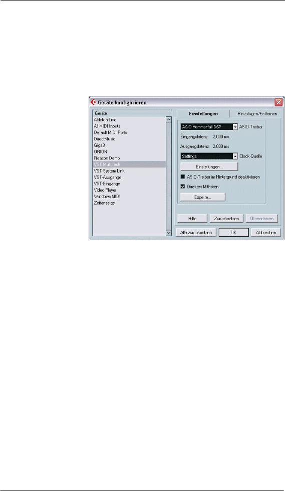
13.1 General
Start the ASIO software and select ASIO Hammerfall DSP as the audio I/O device. The 'ASIO system control' button opens the HDSPe Settings dialog (see chapter 11, Configuration).
13.2 Channel Count under ASIO
At a sample rate of 88.2 or 96 kHz, the ADAT optical input and outputs operate in S/MUX mode, so the number of available channels per port is reduced from 8 to 4.
At a sample rate of 176.4 and 192 kHz, the ADAT optical input and outputs operate in S/MUX4 mode, so the number of available channels per port is limited to 2.
Please note that when changing the sample rate range between Single, Double and Quad Speed the number of channels presented from the ASIO driver will change too. As some channels are removed, SPDIF and AES move up in the list. This may require a reset of the I/O list in the audio software, and will require a reassignment of the channels within the project.
Mono channel |
Double Speed |
Quad Speed |
RayDAT ADAT 1 to 8 |
RayDAT ADAT 1 to 8 |
RayDAT ADAT 1 to 8 |
RayDAT ADAT 9 to 16 |
RayDAT ADAT 9 to 16 |
RayDAT AES L / R |
RayDAT ADAT 17 to 32 |
RayDAT AES L / R |
RayDAT SPDIF L / R |
RayDAT AES L / R |
RayDAT SPDIF L / R |
|
RayDAT SPDIF L / R |
|
|
24 |
User's Guide HDSPe RayDAT © RME |
 Loading...