


User's Guide
Babyface
Portable USB Audio at its best!
TotalMix™
24 Bit / 192 kHz 9 
SteadyClock™ SyncCheck™
USB 2.0 Digital I/O System
22 Channels Analog / ADAT / SPDIF Interface
24 Bit / 192 kHz Digital Audio
20 x 12 Matrix Router
MIDI I/O
MIDI Remote Control

General
1 |
Introduction ............................................................... |
6 |
2 |
Package Contents ..................................................... |
6 |
3 |
System Requirements .............................................. |
6 |
4 |
Brief Description and Characteristics..................... |
6 |
5 |
First Usage - Quick Start |
|
5.1 |
Connectors and Front Panel ................................... |
7 |
5.2 |
Quick Start .............................................................. |
9 |
Installation and Operation - Windows
6 |
Hardware Installation.............................................. |
12 |
7 |
Driver and Firmware |
|
7.1 |
Driver Installation ..................................................... |
12 |
7.2 |
Driver Update........................................................... |
13 |
7.3 |
De-installing the Drivers........................................... |
13 |
7.4 |
Firmware Update ..................................................... |
13 |
8 |
Configuring the Babyface |
|
|
8.1 |
Settings Dialog – General ........................................ |
14 |
|
8.2 |
Settings Dialog – Pitch............................................. |
16 |
|
9 |
Operation and Usage |
|
|
9.1 |
Playback................................................................... |
17 |
|
9.2 |
DVD Playback (AC-3 / DTS) .................................... |
18 |
|
9.3 |
Notes on WDM......................................................... |
19 |
|
9.4 |
Channel Count under WDM..................................... |
20 |
|
9.5 |
Multi-client Operation ............................................... |
20 |
|
9.6 |
Analog Recording..................................................... |
21 |
|
9.7 |
Digital Recording...................................................... |
21 |
|
9.8 |
Digital Connections .................................................. |
22 |
|
9.9 |
Clock Modes - Synchronization ............................... |
23 |
|
10 |
Operation under ASIO |
|
|
10.1 |
General ................................................................ |
24 |
|
10.2 Channel Count under ASIO ................................. |
24 |
||
10.3 |
Known Problems .................................................. |
25 |
|
11 Using more than one Babyface ............................. |
25 |
||
12 |
DIGICheck Windows ............................................... |
26 |
|
13 |
Hotline – Troubleshooting...................................... |
27 |
|
Installation and Operation - Mac OS X
14 |
Hardware Installation.............................................. |
30 |
|
15 |
Driver and Firmware |
|
|
|
15.1 |
Driver Installation ................................................. |
30 |
|
15.2 |
Driver Update ....................................................... |
30 |
|
15.3 |
Firmware Update.................................................. |
31 |
16 |
Configuring the Babyface |
|
|
|
16.1 |
Settings Dialog – General .................................... |
31 |
|
16.2 |
Clock Modes - Synchronization ........................... |
33 |
2 |
User's Guide Babyface © RME |

17 |
Mac OS X FAQ |
|
|
|
17.1 |
Round about Driver Installation ........................... |
34 |
|
17.2 |
MIDI doesn't work ................................................ |
34 |
|
17.3 |
Repairing Disk Permissions................................. |
34 |
|
17.4 |
Supported Sample Rates..................................... |
34 |
|
17.5 |
Channel Count under Core Audio ....................... |
35 |
|
17.6 |
Various Information.............................................. |
35 |
18 |
Using more than one Babyface ............................. |
36 |
|
19 |
DIGICheck Mac........................................................ |
36 |
|
20 |
Hotline – Troubleshooting ..................................... |
37 |
|
TotalMix FX
21 |
TotalMix: Routing and Monitoring |
|
|
|
21.1 |
Overview .............................................................. |
40 |
|
21.2 |
The User Interface ............................................... |
42 |
|
21.3 |
The Channel ........................................................ |
43 |
|
|
Settings.............................................................. |
45 |
|
|
Equalizer ........................................................... |
46 |
|
21.4 |
Section Control Room.......................................... |
47 |
|
21.5 |
The Control Strip.................................................. |
61 |
|
..... |
View Options ..................................................... |
49 |
|
..... |
Snapshots - Groups .......................................... |
50 |
|
21.6 |
Reverb and Echo ................................................. |
51 |
|
21.7 |
Preferences.......................................................... |
53 |
|
21.8 |
Settings ................................................................ |
54 |
|
21.9 |
Hotkeys and Usage ............................................. |
55 |
|
21.10 |
Menu Options....................................................... |
56 |
22 The Matrix |
|
|
22.1 |
Overview .............................................................. |
57 |
22.2 |
The User Interface ............................................... |
57 |
22.3 |
Usage................................................................... |
57 |
23 |
Tips and Tricks |
|
|
|
23.1 |
ASIO Direct Monitoring (Windows)...................... |
58 |
|
23.2 |
Copy a Submix..................................................... |
58 |
|
23.3 |
Delete a Submix................................................... |
58 |
|
23.4 |
Doubling the Output Signal.................................. |
58 |
|
23.5 |
Recording a Submix - Loopback ......................... |
59 |
|
23.6 |
MS Processing..................................................... |
60 |
24 |
MIDI Remote Control |
|
|
|
24.1 |
Overview .............................................................. |
61 |
|
24.2 |
Mapping ............................................................... |
61 |
|
24.3 |
Setup.................................................................... |
62 |
|
24.4 |
Operation ............................................................. |
62 |
|
24.5 |
Simple MIDI Control............................................. |
63 |
|
24.6 |
Loopback Detection ............................................. |
64 |
User's Guide Babyface © RME |
3 |

Technical Reference
25 |
Technical Specifications |
|
|
|
25.1 |
Analog .................................................................. |
66 |
|
25.2 |
MIDI...................................................................... |
66 |
|
25.3 |
Digital ................................................................... |
67 |
|
25.4 |
Digital Inputs ........................................................ |
67 |
|
25.5 |
Digital Outputs...................................................... |
67 |
|
25.6 |
General ................................................................ |
67 |
26 Technical Background |
|
|
26.1 |
Lock and SyncCheck ........................................... |
68 |
26.2 |
Latency and Monitoring........................................ |
69 |
26.3 |
USB Audio............................................................ |
70 |
26.4 |
DS – Double Speed ............................................. |
71 |
26.5 |
QS – Quad Speed................................................ |
71 |
26.6 |
Noise Level in DS / QS Mode .............................. |
72 |
26.7 |
SteadyClock ......................................................... |
72 |
27 |
Diagrams |
|
|
|
27.1 |
Block Diagram Babyface...................................... |
73 |
|
27.2 |
Connector Pinouts................................................ |
74 |
Miscellaneous
28 |
Accessories ............................................................. |
76 |
29 |
Warranty................................................................... |
76 |
30 |
Appendix .................................................................. |
76 |
31 |
Declaration of Conformity...................................... |
78 |
4 |
User's Guide Babyface © RME |

User's Guide
Babyface
General
User's Guide Babyface © RME |
5 |

1. Introduction
Thank you for choosing the RME Babyface. This unique audio system is capable of transferring analog and digital audio data directly to Windows and Mac computers. The latest Plug and Play technology guarantees a simple installation, even for the inexperienced user. Numerous unique features and well thought-out configuration dialog puts the Babyface at the very top of the range of computer-based audio interfaces.
The package contains drivers for Windows XP / Vista / 7 and Mac OS X x86 (Intel).
Our high-performance philosophy guarantees maximum system performance by executing as many functions as possible not in the driver (i.e. the CPU), but within the audio hardware.
2. Package Contents
•Babyface
•Cable USB 2.0 with double power connector
•Breakout cable XLR / TRS / DIN
•D-sub extension cable 1.3m (4.3 ft)
•Carrying bag, meshed grey
•Manual
•RME Driver CD
3. System Requirements
•Windows XP SP2 or up, Intel Mac OS X (10.5 or up)
•1 USB 2.0 port
•Computer with at least Pentium Core 2 Duo CPU
4. Brief Description and Characteristics
•All settings can be changed in real-time
•Buffer sizes/latencies from 48 up to 8192 samples selectable
•4 channels 96 kHz/24 bit Record/Playback via ADAT optical (S/MUX)
•Clock modes slave and master
•Automatic and intelligent master/slave clock control
•Unsurpassed Bitclock PLL (audio synchronization) in ADAT mode
•SteadyClock: Jitter-immune, super-stable digital clock
•DDS technology for free setting of the sample rate
•SyncAlign guarantees sample aligned and never swapping channels
•SyncCheck tests and reports the synchronization status of input signals
•TotalMix for latency-free submixes and perfect ASIO Direct Monitoring
•TotalMix: 264 channel mixer with 42 bit internal resolution
•TotalMix FX: 3-band EQ, Low Cut, Reverb, Echo
•1 x MIDI I/O, 16 channels high-speed MIDI
•2 digitally controlled microphone inputs in reference quality
•2 balanced line outputs, level +15 dBu
•1 x headphone output
•DIGICheck DSP: Level meter in hardware, peakand RMS calculation
6 |
User's Guide Babyface © RME |

5. First Usage – Quick Start
5.1 Connectors - Display
The top of the Babyface features a rotary encoder with push switch function, 2 keys, 2 LED bands and 5 status LEDs.
The two LED bands show the current gain, the input or output level, or indicate the channel to be set, all dependent on the current mode. The lowest LED signals phantom power (+48 V, orange), the highest one overload (Clip, red).
The rotary encoder is used to change various parameters directly at the unit. First the left key Select is used to select the mode which is then displayed by the Status LEDs:
¾Input: Setting the gain of the analog stereo inputs. A push on the encoder changes between left, right or both.
¾Output: Setting the output level of the analog outputs 1/2 at the breakout cable. A push on the encoder activates Dim for the Main Out defined in TotalMix FX (default: Analog 1/2).
¾Phones: Setting the output levels of the analog outputs 3/4. A push on the encoder activates Dim for the Main Out defined in TotalMix FX (default: Analog 1/2).
¾Sync: Synchronisation indicator for the digital optical input (SPDIF, ADAT). Flashes when the signal has been detected but is not fully synchronous. See also chapter 9.9 / 16.2, Clock Modes - Synchronisation.
The key Recall is used to store and load a specific listening volume for the Main Out (default: Analog 1/2) defined in TotalMix FX. Pushing the knob for 2 seconds stores the current setting. If the volume (output level) had been changed a quick hit on the Recall key will restore the former value.
The right side of the Babyface has an instrument input and a headphones output.
The analog input 2 can be switched in TotalMix between line (low impedance, balanced, at the breakout cable) and instrument (high impedance, unbalanced, TRS jack at the unit). See Settings menu of input channel 2.
The analog outputs Phones (channels 3/4) are available at the breakout cable and on the right side of the unit. The connectors are not separated electrically. When connecting two headphones the volume might be reduced. The low impedance and unbalanced output signal is – in terms of quality – identical to the ones at the line outputs, but limited to +7 dBu.
In case the phones output is to be used as line output, usually an adapter TRS plug to RCA phono plugs, or TRS plug to TS plugs is required. More on cable codes and pinouts can be found in chapter 27.2.
User's Guide Babyface © RME |
7 |

The short circuit protected, low impedance line outputs do not operate servo balanced! When connecting unbalanced equipment, make sure pin 3 of the XLR output is not connected. A connection to ground will cause a decreased THD (higher distortion) and increased power consumption!
The Babyface has two analog microphone inputs that can operate as line inputs with levels up to +12 dBu, when set to 0 dB gain. The electronic input stage uses a servo balanced design which handles unbalanced and balanced signals correctly, automatically adjusting the level reference.
When using unbalanced cables with the XLR breakout cable: be sure to connect the 'ring' contact of a stereo TRS jack, and pin 3 of a XLR jack, to ground. Otherwise noise may occur, caused by the unconnected negative input of the balanced input.
The rear of the Babyface has an optical input and output, a power supply connector, a USB socket and a 15-pin D-sub connector for the included breakout cable.
Optical Out |
USB 2.0 |
|
Breakout cable |
Optical In |
Power |
Optical I/O (TOSLINK): The unit automatically detects SPDIF or ADAT input signals. The optical output can operate as ADAT or SPDIF output, depending on the current setting in the Settings dialog.
USB 2.0: USB socket for connection to the computer.
Socket for power connection. Unburdens the computer’s power supply, or ensures a stable power supply, in case it proves to be insufficient when taken from the computer. If the power supply via standard USB cables is not sufficient the included special dual power cable can also be used.
The included breakout cable provides these connections:
¾Microphone/Line In: 2 x XLR, balanced
¾Line Out: 2 x XLR, balanced
¾Phones Output: 1 x stereo TRS ¼” (6.3 mm), unbalanced. Can also be used as additional line output.
¾MIDI I/O: One MIDI input and output via 5-pin DIN connector.
If the breakout cable turns your desktop into a mess the included extension cable comes to the rescue. It is simply inserted between the breakout cable and the D-sub connector of the Babyface. Then both breakout cable and all cables connected to it will be out of sight, without decreasing the Babyface’s technical specifications or performance.
8 |
User's Guide Babyface © RME |

5.2 Quick Start
After the driver installation (chapter 7 / 15), connect the inputs to the analog signal source. Mount the included breakout cable with or without the extension cable to the D-sub connector of the Babyface.
The analog input sensitivity can be changed at the unit (Select In) or in TotalMix (Settings, Gain), assuring the highest signal to noise ratio will be achieved. Also try to achieve an optimum input level by adjusting the source itself. Raise the source’s output level until the peak level meters in TotalMix reach about –3 dB.
The analog line inputs of the Babyface can be used with +4 dBu and -10 dBV signals. The electronic input stage can handle balanced (XLR, TRS jacks) and unbalanced (TS jacks) input signals correctly.
The Babyface's digital output supports the formats SPDIF and ADAT optical.
On the analog playback side (the DA side), an adjustment of the analog output level can be done by the rotary encoder (Select Out or Phones), or in TotalMix FX.
The output signal of channels 3/4, Phones, is also available at the unit. The output level can be set freely using the rotary encoder. This output is a low impedance type, which can also be used to connect headphones.
TotalMix FX remembers all settings, and loads these automatically when the Babyface drivers are loaded.
User's Guide Babyface © RME |
9 |

10 |
User's Guide Babyface © RME |
User's Guide
Babyface
Installation and Operation - Windows
User's Guide Babyface © RME |
11 |

6. Hardware Installation
Connect computer and Babyface with the supplied USB cable. Turn on the computer. That‘s it.
Chapter 26.3 explains how to find the ideal USB port.
7. Driver and Firmware
7.1 Driver Installation
After the Babyface has been recognized, (see 9. Hardware Installation) the hardware assistant finds a Babyface. Insert the RME Driver CD into your CD-ROM drive, and follow further instructions which appear on your computer screen. The driver files are located in the directory \Babyface on the RME Driver CD.
Windows now installs the driver of the Babyface and registers it as a new audio device in the system. After a reboot, the symbols of TotalMix and Settings dialog will appear in the task bar.
In case the Hardware Wizard does not show up automatically after connecting the Babyface, do not attempt to install the drivers manually! An installation of drivers for nonrecognized hardware can cause a blue screen when booting Windows!
In Windows 7 Microsoft removed the automatic start of the Driver Software Update dialog. Therefore this dialog has to be started manually after the failed driver installation. Hit the Windows key, type 'Device Manager', start the Device Manager by selecting it from the list and hit Enter.
The device is shown with a yellow warning symbol. Usually it is already found in the correct category, Sound, Video and Game Controller (Plug & Play detects a multimedia device). Right click on the device and select 'Update Driver Software' from the context menu.
The dialog Update Driver Software appears. Now follow the instructions given below.
Possible reasons why a Babyface is not found automatically:
•The USB port is not active in the system (check the Device Manager)
•The USB cable is not, or not correctly inserted into the socket
•The Babyface does not receive any or not enough power. In this case please use the included dual cable. Plug both connectors from one end of the cable into the computer. If the Babyface starts correctly the lowest green LED in the left band will flash, the In LED is constantly lit, the lowest one in the right band too.
12 |
User's Guide Babyface © RME |

7.2 Driver Update
When facing problems with the automatic driver update, the user-driven way of driver installation will work.
Under >Control Panel /System /Device Manager /Sound, Video and Game Controllers /RME Babyface/Properties /Driver< you'll find the 'Update Driver' button.
XP: Select 'Install from a list or specific location (advanced)', click 'Next', select 'Don't search I will choose the driver to install', click 'Next', then 'Have Disk'. Now point to the driver update's directory.
Vista/7: Select 'Browse my computer for driver software', then 'Let me pick from a list of device drivers from my computer', then 'Have Disk'. Now point to the driver update's directory.
This method also allows for the installation of older drivers than the currently installed ones.
7.3 De-installing the Drivers
A de-installation of the driver files is not necessary – and not supported by Windows anyway. Thanks to full Plug & Play support, the driver files will not be loaded after the hardware has been removed. If desired these files can then be deleted manually.
Unfortunately Windows Plug & Play methods do not cover the additional autorun entries of TotalMix, the Settings dialog, and the registration of the ASIO driver. These entries can be removed from the registry by a software de-installation request. This request can be found (like all de-installation entries) in Control Panel, Add or Remove Programs (Vista/7: Programs and Features). Click on the entry 'RME Fireface USB'.
7.4 Firmware Update
The Flash Update Tool updates the firmware of the Babyface to the latest version. It requires an already installed driver.
Start the program fut_usb.exe. The Flash Update Tool displays the current revision of the Babyface's firmware, and whether it needs an update or not. If so, then simply press the 'Update' button. A progress bar will indicate when the flash process is finished (Verify Ok).
After the update the Babyface needs to be reset. This is done by powering down the Babyface for a short time.
Attention: the Babyface should not be switched off for less than 5 seconds, because Windows completely unloads the driver, which takes some time to finish.
A reboot of the computer is not necessary.
When the update fails (status: failure), the unit's Safety BIOS will be used from the next boot on, the unit stays fully functional. The flash process should then be tried again.
User's Guide Babyface © RME |
13 |

8. Configuring the Babyface
8.1 Settings Dialog - General
Configuration of the Babyface is done via its own settings dialog. The panel 'Settings' can be opened:
• by clicking on the fire symbol in the Task Bar's notification area
The mixer of the Babyface (TotalMix) can be opened:
• by clicking on the double arrow symbol in the Task Bar's notification area
The hardware of the Babyface offers a number of helpful, well thought-out practical functions and options which affect how the card operates - it can be configured to suit many different requirements.
The following is available in the Settings dialog:
•Latency
•Operation of the DSP
•Configuration of the digital I/O
•Current sample rate
•Synchronization behaviour
•State of input and output
Any changes made in the Settings dialog are applied immediately - confirmation (e.g. by clicking on OK or exiting the dialog) is not required.
However, settings should not be changed during playback or record if it can be avoided, as this can cause unwanted noises.
Also, please note that even in 'Stop' mode, several programs keep the recording and playback devices open, which means that any new settings might not be applied immediately.
14 |
User's Guide Babyface © RME |

Buffer Size
The setting Buffer Size determines the latency between incoming and outgoing ASIO and WDM data, as well as affecting system stability (see chapter 9.1 / 10).
Errors does not refer to buffer errors, but USB transmission errors. The display will be reset on any start of a playback/record. More information can be found in chapter 26.3.
Options
DSP – EQ for Record
Switches the 3-band EQ and Low Cut of all input channels into the recording path. In case Loopback has been activated the EQ and Low Cut of the Output channel is placed into the recording path. See also chapter 23.5.
Optical Out
The optical TOSLINK output can operate as ADAT or SPDIF output. The Channel Status is fixed to Consumer state.
Note: The optical input detects the incoming format automatically.
SPDIF In
TMS activates the transmission of Channel Status data and Track Marker information from the SPDIF input signal.
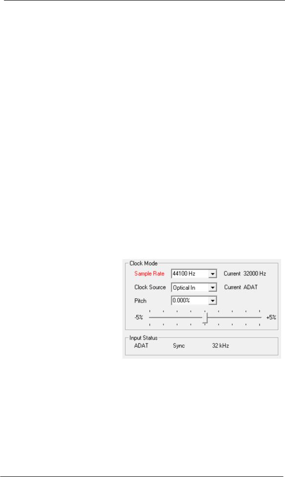
Clock Mode
Sample Rate
Sets the currently used sample rate. Offers a central and comfortable way of configuring the sample rate of all WDM devices to the same value, as since Vista the audio software is no longer allowed to set the sample rate. However, an ASIO program can still set the sample rate by itself.
During record/playback the selection is greyed out, so no change is possible.
Clock Source
The unit can be configured to use its own clock (Internal = Master) or the digital input signal (Optical = Slave). If the external source isn't available (Input Status No Lock), the unit will change to the internal clock. The current clock source is displayed as Current.
Pitch
More information on Pitch is available in chapter 8.2.
Input Status
Indicates presence of a valid signal at the optical input (Lock, No Lock) and whether the signal is synchronous (Sync). The third column shows the sample frequency detected by the hardware (coarse recognition, 32 kHz, 44.1 kHz, 48 kHz etc.). In Clock Mode the clock reference is shown. See also chapter 26.1.
The About tab includes information about the current driver version as well as the current firmware version of the Babyface.
User's Guide Babyface © RME |
15 |

8.2 Settings Dialog - Pitch
Usually soundcards and audio interfaces generate their internal clock (master mode) by a quartz. Therefore the internal clock can be set to 44.1 kHz or 48 kHz, but not to a value in between. SteadyClock, RME's sensational Low Jitter Clock System, is based on a Direct Digital Synthesizer (DDS). This superior circuitry can generate nearly any frequency with highest precision.
DDS has been implemented into the Babyface with regard to the needs of professional video applications, as well as to maximum flexibility. The section Pitch includes both a list of typical video frequencies (so called pull up/pull down at 0.1% and 4%) and a fader to freely change the basic sample rate in steps of 1 Hz (!) over a range of +/- 5%.
The Pitch function requires the Babyface to be in clock mode Master (Internal)! The frequency setting will only be applied to this one specific Babyface!
Changing the sample rate during record/playback often results in a loss of audio, or brings up warning messages of the audio software. Therefore the desired sample rate should be set at least coarsely before starting the software.
Coarse
Coarse modification in steps of 50 Hz is done by clicking with the mouse to the left and right of the fader knob.
Fine
Fine modification in steps of 1 Hz is done by using the left/right cursor keys.
Reset
Ctrl key plus left mouse click.
Application examples
Pitch allows for a simultaneous change of speed and tune during record and playback. From alignment to other sources up to creative effects – everything is possible.
Pitch enables you to intentionally de-tune the complete DAW. This way, the DAW can match instruments which have a wrong or unchangeable tuning.
Pitch allows for the change of the sample rate of all WDM devices at the same time. Since Vista this is no longer possible via the audio program, thus requires a manual reconfiguration of all WDM devices. Changing the sample rate from the Settings dialog solves this problem. As the change within the system requires some time, record/playback should not be started immediately, but only after at least 5 seconds after a change.
Tip: the current CPU load can be used to determine if the audio subsystem has finished the reconfiguration.
16 |
User's Guide Babyface © RME |

9. Operation and Usage
9.1 Playback
In the audio application being used, Babyface must be selected as output device. It can often be found in the Options, Preferences or Settings menus, as Playback Device, Audio Devices, Audio etc.
We recommend switching all system sounds off (via >Control Panel /Sound<). Also Babyface should not be the Preferred Device for playback, as this could cause loss of synchronization and unwanted noises. If you feel you cannot do without system sounds, you should consider using the on-board sound device or buying a cheap Blaster clone and select this as Preferred Device in >Control Panel /Multimedia /Audio< or >Control Panel /Sound /Playback<.
The screenshot shows a typical configuration dialog. After selecting a device, audio data is sent to an analog or digital port, depending on which has been selected as playback device.
Increasing the number and/or size of audio buffers may prevent the audio signal from breaking up, but also increases latency i.e. output is delayed. For synchronized playback of audio and MIDI (or similar), be sure to activate the checkbox ‘Get position from audio driver’.
Note on Windows Vista/7:
Since Vista the audio application can no longer control the sample rate under WDM. Instead the user has to work himself through numerous settings (up to 32 with a MADI card!), and to set the sample rate to the same value per stereo device.
Therefore the driver of the Babyface includes a workaround: the sample rate can be set globally for all WDM devices within the Settings dialog, see chapter 9.1.
User's Guide Babyface © RME |
17 |

9.2 DVD-Playback (AC-3/DTS)
AC-3 / DTS
When using popular DVD software players like WinDVD and PowerDVD, their audio data stream can be sent to any AC-3/DTS capable receiver using the Babyface's SPDIF output. For this to work, the WDM SPDIF device of the Babyface has to be selected in >Control Panel/ Sounds and Multimedia/ Audio< or >Control Panel/ Sound/Playback<. Also check 'use preferred device only'.
The DVD software's audio properties now show the options 'SPDIF Out' or similar. When selecting it, the software will transfer the non-decoded digital multichannel data stream to the Babyface.
Note: This 'SPDIF' signal sounds like chopped noise at highest level. Try to avoid mixing and routing the signal to your loudspeakers, as they might get damaged.
Multichannel
PowerDVD and WinDVD can also operate as software decoder, sending a DVD's multichannel data stream directly to the analog outputs of the Babyface. For this to work select the WDM playback device ’Loudspeaker’ of the Babyface in
XP: >Control Panel/ Sounds and Multimedia/ Audio<, and check 'Use only default devices'. Additionally the loudspeaker setup, found under >Volume/ Speaker Settings/ Advanced< has to be changed from Stereo to 5.1 Surround.
Vista/7: >Control Panel/ Sound/ Playback < as ‘Standard’. Additionally the loudspeaker setup, found under >Configuration<, has to be changed from Stereo to 5.1 Surround.
PowerDVD's and WinDVD's audio properties now list several multichannel modes. If one of these is selected, the software sends the decoded analog multichannel data to the Babyface. TotalMix can then be used to play back via any desired output channels.
The typical channel assignment for surround playback is:
1 - Left
2 - Right
3 - Center
4 - LFE (Low Frequency Effects)
5 - SL (Surround Left)
6 - SR (Surround Right)
Note 1: Selecting the Babyface to be used as system playback device is against our recommendations, as professional interfaces should not be disturbed by system events. Make sure to re-assign the selection after usage or to disable any system sounds (tab Sounds, scheme 'No audio').
Note 2: The DVD player will be synced backwards from the Babyface. This means when using AutoSync and/or word clock, the playback speed and pitch follows the incoming clock signal.
18 |
User's Guide Babyface © RME |

9.3 Notes on WDM
The driver offers one WDM streaming device per stereo pair, like Analog 3+4 (Babyface). WDM Streaming is Microsoft's current driver and audio system, directly embedded into the operating system. WDM Streaming is hardly usable for professional music purposes, as all data is processed by the so called Kernel Mixer, causing a latency of at least 30 ms. Additionally, WDM can perform sample rate conversions unnoticed, cause offsets between record and playback data, block channels unintentionally and much more.
Several programs do not offer any direct device selection. Instead they use the playback device selected in Windows under
XP: <Control Panel/ Sounds and Multimedia/ Audio>
Vista/7: <Control Panel/ Sound/ Playback>
The program Sonar from Cakewalk is unique in many ways. Sonar uses the so called WDM Kernel Streaming, bypassing the WDM mixer, thus achieves a similar performance to ASIO (see below).
Because of the driver's multichannel streaming ability, Sonar not only finds the stereo device mentioned above, but also the 8-channel interleaved devices, and adds the channel number at the end:
Babyface Analog (1+2) 1/2 is the first stereo device Babyface Analog (3+4) is the next stereo device
Babyface Analog (1+2) 3/4 are the channels 3/4 of the first 8-channel interleaved device.
It is not recommended to use these special interleaved devices. Also it is not possible to use one stereo channel twice (the basic and the interleaved device).
Multi-Channel using WDM
The WDM Streaming device Loudspeaker (Analog 1+2) of the RME driver can operate as usual stereo device, or as up to 8-channel device.
An 8-channel playback using the Windows Media Player requires the speaker setup 7.1 Surround. Configure as follows:
XP: >Control Panel /Sounds and Multimedia /Audio /Volume /Speaker Settings /Advanced <
Vista/7: >Control Panel /Sound /Playback /Loudspeaker /Configure <
User's Guide Babyface © RME |
19 |

9.4 Channel Count under WDM
The Babyface’s ADAT optical interface offers sample rates of up to 192 kHz using a standard ADAT recorder. For this to work single-channel data is spread to two or four ADAT channels using the Sample Multiplexing technique. This reduces the number of available ADAT channels from 8 to 4 or 2 per ADAT port.
Whenever the Babyface changes into Double Speed (88.2/96 kHz) or Quad Speed mode (176.4/192 kHz) all devices no longer available vanish automatically.
WDM Stereo device |
Double Speed |
Quad Speed |
Babyface Analog (1+2) |
Babyface Analog (1+2) |
Babyface Analog (1+2) |
Babyface Analog (3+4) |
Babyface Analog (3+4) |
Babyface Analog (3+4) |
Babyface AS (1+2) |
Babyface AS (1+2) |
Babyface AS (1+2) |
Babyface ADAT (3+4) |
Babyface ADAT (3+4) |
Babyface ADAT (3+4) |
Babyface ADAT (5+6) |
Babyface ADAT (5+6) |
Babyface ADAT (5+6) |
Babyface ADAT (7+8) |
Babyface ADAT (7+8) |
Babyface ADAT (7+8) |
Note: Under Vista/7 the analog outputs 1/2 show up as Loudspeaker.
9.5 Multi-client Operation
RME audio interfaces support multi-client operation. This means several programs can be used at the same time. Also ASIO and WDM can be used simultaneously. The use of multi-client operation requires to follow two simple rules:
•Multi-client operation requires identical sample rates!
I.e. it is not possible to use a software with 44.1 kHz and another one with 48 kHz.
•Different software can not use the same playback channels at the same time.
If for example Cubase uses channels 1/2, this playback pair can't be used in WaveLab, no matter if ASIO or WDM. However, this is no limitation at all, because TotalMix allows for any output routing, and therefore a playback of multiple software on the same hardware outputs. Note that identical inputs can be used at the same time, as the driver simply sends the data to all applications simultaneously.
ASIO-Multiclient
RME audio interfaces support ASIO multi-client operation. It is possible to use more than one ASIO software at the same time. Again the sample rate has to be identical, and each software has to use its own playback channels. Again the inputs can be used simultaneously.
RME's sophisticated tool DIGICheck is an exception to this rule. It operates like an ASIO host, using a special technique to access playback channels already occupied. Therefore DIGICheck is able to analyse and display playback data from any software, no matter which format the software uses.
20 |
User's Guide Babyface © RME |
9.6 Analog Recording
For recordings via the analog inputs the corresponding record device has to be chosen (Babyface Analog (x+x)).
Channels 1 and 2 of the Babyface have digitally controlled microphone preamps of the highest quality. The digital control offers a gain setting in steps of 3 dB within a range of 9 dB to 60 dB. The configuration is done either directly at the unit via the rotary encoder, or via the Settings panel of the input channels 1 and 2 in TotalMix, with the knob Gain. The current gain is displayed in dB beside the knob.
In the lower range the knob jumps from 9 dB to 0 dB. This useful additional setting provides line signal compatibility at up to +12 dBu at the microphone input.
Above the knob Gain the inputs can be set separately to provide 48V phantom power at the XLR connectors. Phantom power is required for condenser microphones.
Input channel 2 can be switched to the TRS jack on the right side of the Babyface. The Hi-Z instrument input has an input impedance of 470 kOhm. The input gain is controlled by the same knob, but the gain range now starts at +9 dB.
It often makes sense to monitor the input signal or send it directly to the output. This can be done at zero latency using TotalMix (see chapter 21).
An automated control of real-time monitoring can be achieved by Steinberg’s ASIO protocol with RME’s ASIO drivers and any ASIO 2.0 compatible program. When 'ASIO Direct Monitoring' has been switched on, the input signal is routed in real-time to the output whenever a recording is started (punch-in).
9.7 Digital Recording
Unlike analog soundcards which produce empty wave files (or noise) when no input signal is present, digital interfaces always need a valid input signal to start recording.
Taking this into account, RME added a comprehensive I/O signal status display to the Babyface, showing sample frequency, lock and sync status in the Settings dialog, and a status LED directly at the unit.
The sample frequency shown in the Settings dialog is useful as a quick display of the current configuration of the unit and the connected external equipment. If no sample frequency is recognized, it will read ‘No Lock’.
This way, configuring any suitable audio application for digital recording is simple. After connection the Babyface displays the current and external sample frequency. This parameter can then be changed in the application’s audio attributes (or similar) dialog.
User's Guide Babyface © RME |
21 |

9.8 Digital Connections
ADAT
The ADAT optical input of the Babyface is fully compatible with all ADAT optical outputs. RME's unsurpassed Bitclock PLL prevents clicks and drop outs even in extreme varipitch operation, and guarantees a fast and low jitter lock to the digital input signal. A usual TOSLINK cable is sufficient for connection. More information on Double Speed (S/MUX) can be found in chapter 26.4.
ADAT In
Interface for a device sending an ADAT signal to the Babyface. Carries the channels 1 to 8. When receiving a Double Speed signal, this input carries the channels 1 to 4, at Quad Speed the inputs 1 and 2.
ADAT Out
Interface for a device receiving an ADAT signal from the Babyface. Transmits channels 1 to 8. When sending a Double Speed signal, this port carries channels 1 to 4, at Quad Speed the channels 1 and 2.
Note: To use the optical output as ADAT port set the option Optical to ADAT in the Settings dialog.
SPDIF
The optical input automatically switches to SPDIF operation when such a signal is detected. The audio information is then shown in TotalMix on the first two ADAT channels, AS 1 and AS 2.
Activating the option TMS in the Windows Settings dialog enables RME’s DIGICheck to analyze the Channel Status of the input signal.
To send out SPDIF from the optical output, select the option Optical – SPDIF in the Settings dialog. The output signal in TotalMix has to be present on the first ADAT channels, AS 1+2.
MIDI
Babyface offers one MIDI I/O via two 5-pin DIN jacks. The MIDI ports are added to the system by the driver. Using MIDI capable software, these ports can be accessed under the name Babyface Midi. Using more than one Babyface, the operating system adds a consecutive number to the port name, like Babyface MIDI (2) etc.
The MIDI ports support multi-client operation. A MIDI input signal can be received from several programs at the same time. Even the MIDI output can be used by multiple programs simultaneously. However, due to the limited bandwidth of MIDI, this kind of application will often show various problems.
22 |
User's Guide Babyface © RME |
9.9 Clock Modes - Synchronization
In the digital world, all devices must be either Master (clock source) or Slave (clock receiver).. Whenever several devices are linked within a system, there must always be a single master clock.
A digital system can only have one master! If the Babyface’s clock mode is set to 'Internal', all other devices must be set to ‘Slave’.
The Babyface utilizes a very user-friendly, intelligent clock control, called AutoSync. Selecting Optical as Clock Source, the system constantly scans the digital input for a valid signal. If any valid signal is found, the Babyface switches from the internal quartz (Clock Mode – Current Internal) to a clock extracted from the input signal (Clock Mode – Current ADAT or SPDIF). The difference to a usual slave mode is that whenever the clock reference fails, the system will automatically use its internal clock and operate in clock mode Master.
AutoSync guarantees that record and record-while-play will always work correctly. In certain cases however, e.g. when the inputs and outputs of a DAT machine are connected directly to the Babyface, AutoSync may cause feedback in the digital carrier, so synchronization breaks down. To solve this problem switch the Babyface clock mode to Master (Clock Source – Internal).
In some situations changing the clock mode can not be avoided. Example: A CD player is connected to the SPDIF input. Try recording a few samples from the CD and you will be disappointed - few CD players can be synchronized. The samples will inevitably be corrupted, because the signal from the CD player is read with the clock from the Babyface, being out of sync. In this case, the Clock Source should be set temporarily to SPDIF.
RME’s exclusive SyncCheck technology (first implemented in the Hammerfall) enables an easy to use check and display of the current clock status. Input Status indicates whether there is a valid signal (Lock, No Lock) for the optical input, or if there is a valid and synchronous signal (Sync). In the field Clock Mode the clock reference is shown. See chapter 26.1.
Under WDM the Babyface will (has to) set the sample rate. Therefore the error shown to the right can occur. A stable signal with a sample rate of 32 kHz is detected at the ADAT input (Sync), but Windows audio had been set to 44100 Hz before. The red color of the text label signals the error condition, and prompts the user to set 32000 Hz manually as sample rate. Under ASIO the audio software sets the sample rate, so that such an error can not happen. If the input sample rate is different then there will be no Sync indication.
With RME’s AutoSync and SyncCheck, finally anyone can master this common source of error, previously one of the most complex issues in the digital studio world.
User's Guide Babyface © RME |
23 |

10. Operation under ASIO
10.1 General
Start the ASIO software and select ASIO Fireface USB as the audio I/O device or the audio driver.
The Babyface supports ASIO Direct Monitoring (ADM).
The Babyface MIDI I/O can be used with both MME MIDI and DirectMusic MIDI.
10.2 Channel Count under ASIO
At a sample rate of 88.2 or 96 kHz, the ADAT optical input and output operates in S/MUX mode, so the number of available channels is reduced from 8 to 4.
At a sample rate of 176.4 and 192 kHz, the ADAT optical input and output operates in S/MUX4 mode, so the number of available channels is limited to 2.
Note: When changing the sample rate range between Single, Double and Quad Speed the number of channels presented from the ASIO driver will change too. This may require a reset of the I/O list in the audio software.
Single Speed |
Double Speed |
Quad Speed |
Babyface Analog 1 to 4 |
Babyface Analog 1 to 4 |
Babyface Analog 1 to 4 |
Babyface AS 1 to 2 |
Babyface AS 1 to 2 |
Babyface AS 1 to 2 |
Babyface ADAT 3 to 4 |
Babyface ADAT 3 to 4 |
Babyface ADAT 3 to 4 |
Babyface ADAT 5 to 6 |
Babyface ADAT 5 to 6 |
Babyface ADAT 5 to 6 |
Babyface ADAT 7 to 8 |
Babyface ADAT 7 to 8 |
Babyface ADAT 7 to 8 |
24 |
User's Guide Babyface © RME |
 Loading...