

Page 1

Portable Gas Leak Detec t or
SP-220 Series
TYPE F
Operating Manual
Part Number: 7 1-0421
Revision : P1
Released: 10/20/17
Page 2

- 2 -
Contents
Table of Contents
1. Outline of the Product ..................................................................................................................................... 3
Preface ............................................................................................................................................................ 3
Purpose of use ................................................................................................................................................ 3
Definition of DANGER, WARNING, CAUT IO N an d NO TE ............................................................................. 3
How to check the standards and explosion-proof specifications ................................................................... 4
2. Important Notices on Safety ........................................................................................................................... 5
2-1. Danger cases........................................................................................................................................... 5
2-2. Warning cases ......................................................................................................................................... 6
2-3. Precauti ons .............................................................................................................................................. 7
2-4. Safety infor mation (for ATEX/IECEx specifications) ................................................................................ 9
3. Product Components .................................................................................................................................... 10
3-1. Names and fu nc t i o ns for each part ....................................................................................................... 10
4. How to Use ................................................................................................................................................... 13
4-1. Before usi n g th e de tector ...................................................................................................................... 13
4-2. Preparation for start-up .......................................................................................................................... 13
4-3. How to replace the batteries .................................................................................................................. 13
4-4. How to start the detector ....................................................................................................................... 15
4-5. Basic opera ting procedures ................................................................................................................... 17
4-6. How to detect ......................................................................................................................................... 18
4-7. Changing the concentration measuring mode ...................................................................................... 19
4-8. Perform in g ai r c al ibr a t i on ...................................................................................................................... 22
4-9. Snap logger ........................................................................................................................................... 23
4-10. Peak hold function ............................................................................................................................... 24
4-11. Changing the alarm and operation sounds ......................................................................................... 24
4-12. How to turn on th e i l l umination lamp ................................................................................................... 25
4-13. Power-off ............................................................................................................................................. 25
5. Display Mode ................................................................................................................................................ 26
5-1. Entering the display mode ..................................................................................................................... 26
5-2. Measured g as reading setting ............................................................................................................... 29
5-3. Changing the measuring mode ............................................................................................................. 31
5-4. Log data display .................................................................................................................................... 32
6. User Mode .................................................................................................................................................... 33
6-1. Entering th e user mode ......................................................................................................................... 33
6-2. Date/time setting .................................................................................................................................... 35
6-3. Clock function ON/OFF setting .............................................................................................................. 36
7. Alarm Function .............................................................................................................................................. 37
7-1. Gas alarm activation .............................................................................................................................. 37
7-2. Fault alarm activation ............................................................................................................................ 37
8. Maintenance ................................................................................................................................................. 38
8-1. Maintena nce intervals and items ........................................................................................................... 38
8-2. How to clean .......................................................................................................................................... 40
8-3. Parts replacement ................................................................................................................................. 40
9. Calibration Mode .......................................................................................................................................... 43
9-1. Fresh Air Adjustment ............................................................................................................................. 43
9-2. Preparing for a Span Adjustment (Gas Ba g) ......................................................................................... 45
9-3. Preparing for a Span Adjustment (Deman d Flow Regulator) ................................................................ 46
9-4. Automatic Span Adjustment ................................................................................................................... 46
9-5. Manual Span Adjustment ....................................................................................................................... 49
9-6. Password ............................................................................................................................................... 51
10. Storage and Disposal ................................................................................................................................. 54
10-1. Procedures to store the detector or leave it for a long time ................................................................ 54
10-2. Procedures to use the detec tor again ................................................................................................. 54
10-3. Disposal of products ............................................................................................................................ 55
11. Troubleshooting .......................................................................................................................................... 56
12. Spare Parts List .......................................................................................................................................... 58
13. Product Specificat io ns ................................................................................................................................ 59
Page 3
- 3 -
1
1. Outline of the Product
Preface
Thank you for choosin g our portable gas leak det ec t or S P-220 TYPE F (hereinafter referred to as the
detector). Pl ease check that the m od el number of the product you purchased is include d i n th e
specifications on this manual.
This manual ex p la i ns how to use the detector and its specifications. It contains information required for
using the detector properly. First-time users and users who have already used the product m ust r ea d a nd
understand the o perating manual to en h ance the knowledg e a nd experience before using the detector.
Note that the contents of this manual are subject to change without notice for product improvement. It is
also prohibit ed to c o p y or reproduce this manu a l, in whole or in part, withou t permission.
Regardless of warranty period, we shall not make any indemnification for accidents and damage caused by
using the detec t or.
Make sure to read the warranty policy specified on the warranty.
Purpose of use
This detector is us e d to de tect fluorocarbons leaking out in air.
Detection results are not intended to guarantee life or safety in any way.
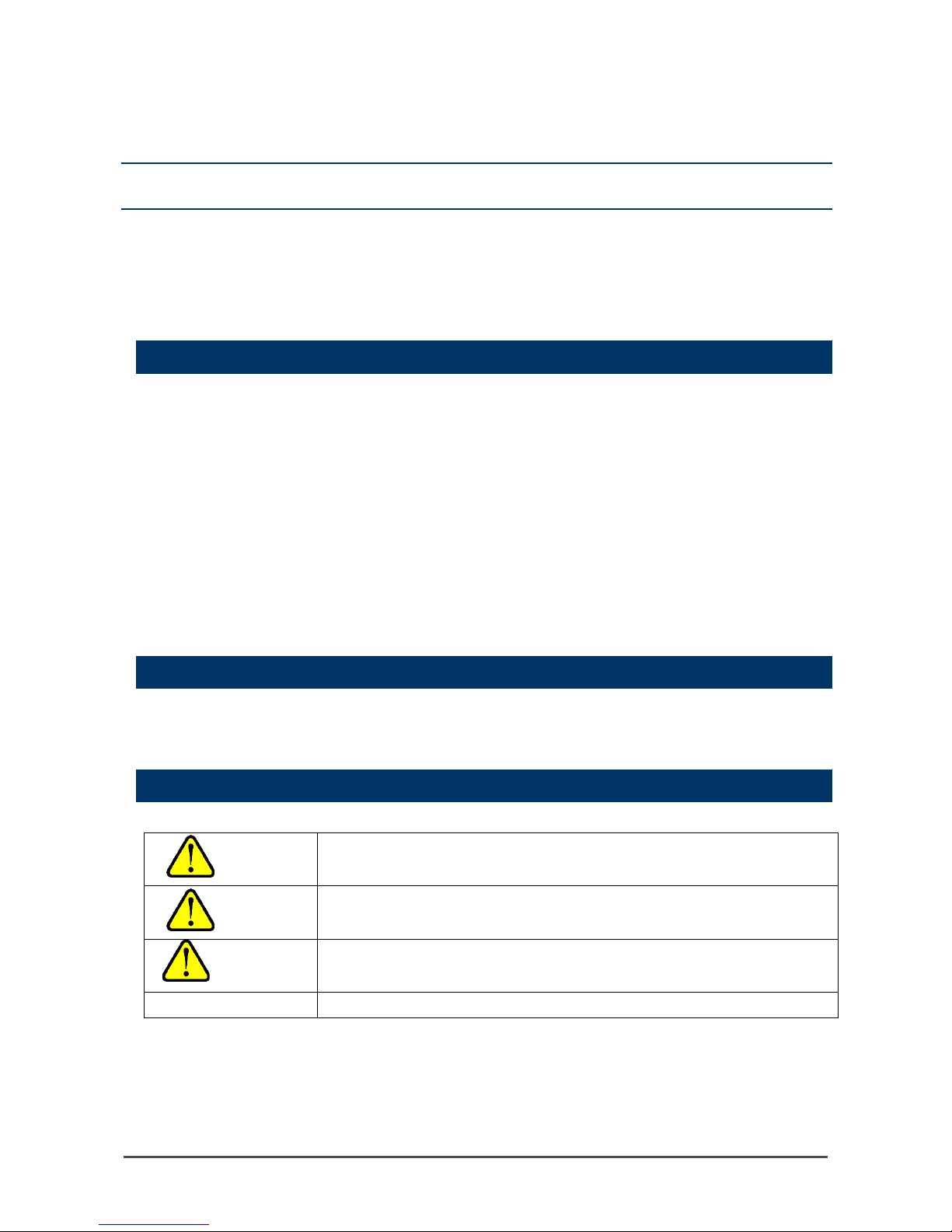
Definition of DANGER, WARNING, CAUTION and NOTE
Throughout this manual, the following indications are used to ensure safe and effective work.
DANGER
This message indicates that improper handling may cause serious
damage on life, health or assets.
WARNING
This message indicates that improper handling may cause serious
damage on health or assets.
CAUTION
This message indicates that improper handling may cause minor damage
on health or assets.
NOTE
This message indicates advice on handling.
Page 4
- 4 -
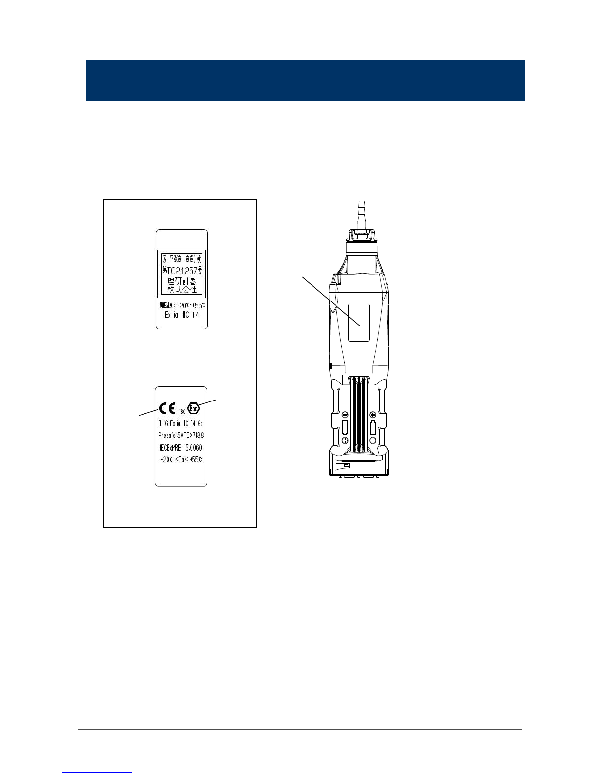
How to check the standards and explosion-proof
specifications
The detector has d ifferent specificati ons depending on the sta nd ards or explosion-proof certification type.
Check the specifications of the product you ha v e bef ore use. See the Declar ation of Conformity at the end
of this operating manual for CE marking specifications.
For the product specifications, check the nameplate attached to the product shown in the following figure.
(1) Nameplate exampl e of TIIS
specifications
(2) Nameplate exampl e of CE marking
specifications
* The above nameplate (1) or (2) is
attached depending on th e specified
explosion-proof spec i fications.
Ex mark
CE mark
Page 5

- 5 -
2
2. Important Notices on
Safety
To maintain the performance and use the det ec t or safely, observe the following instructions of DANGER,
WARNING, and CAUTION.
2-1. Danger cases
DANGER
About use
• While conducting measurement in a manhole or confined space, do not lean over or look into
the manhole or closed space. It may lead to dangers because oxygen-deficient air or other
gases may blow ou t.
• Oxygen-deficient air or oth er gases may be discharg e d f rom the gas exhaustin g ou t le t of the
detector. Never inhale t he air or gases.
• High-concentration (100% LEL or higher) gases may be discharged from the gas exhausting
outlet of the detector. Never use fire near it.
Page 6
- 6 -
2-2. Warning cases
WARNING
Sampling point pressure
• The concentration meter is designed to draw gases under the atmospheric pressure. If
excessive pres sure is applied to th e g as in l et an d ou t l et of t h e de t ec t or, measure d gases may
leak out from its inside and may cause dangerous conditions. Be sure that excessive pressure
is not applied to th e de t ec t or’s gas inlet or ou tl e t during use.
Air calibration in atmosphere
• Perform an air calibration in a fresh air environment. If interference gases or other gases exist,
the adjustmen t c an n ot be performed prop erly, thus leading to da ng er s wh e n gas is present.
Response to gas alarm
• A gas alarm is triggered by changes in temperature and humidity. In such a case, check the
atmosphere for freshness and perform air calibration again in the measured atmosphere.
Example) If th e de t ec t or is t ur n e d on in a ro om with a temperature of 20 ºC an d a humidity of
40% RH and taken outs id e ( a temperature of 30ºC a nd a humidity of 60% RH), an alar m is
triggered by humidity changes. In such a case, perform air calibration outside and measure.
The detector per f or ms air calibration a ut omatically when it is tur n e d on . E v en in s uch a case,
check the atmosphere for freshness and perform air calibration again in the measured
atmosphere.
WARNING
Battery level check
• Before use, check that there remains sufficient battery power . When the detector is not used for
a long period, the batteries may be exhausted. Never fail to replace them with new ones before
use.
• If a low battery voltage alarm is triggered, gas detection cannot be conducted. If the alarm is
triggered during use, turn off the power and promptly replace the batteries in a safe area.
Others
• Do not throw the detector into fire.
• Do not wash the detector in a washing machine or ultrasonic cleaner, etc.
• Do not block the buzzer sound opening. No alarm sound can be heard.
• Do not remove the battery while the power is on.
Page 7

- 7 -
2-3. Precautions
CAUTION
Do not use the detector where it is exposed to oil, chemicals, etc. Do not submerge the detector
under water on purpose.
• Do not use in a plac e wh ere the detector is exp osed to liquids such as o il an d c h emicals.
• The detector is not water-pressure-resistant. Do not use the detector where a high water pressure is
applied to it (under a faucet, shower, etc.) or submerge it under water for a long time. The detector
is water-proof only in fresh wa ter and running water, and not in hot wat er, salt wat er, detergen t,
chemicals, human sweat, etc.
• The gas inlet and outlet are not water-proof. Be careful not to let water such as rainwater, etc. get
into these parts. Because this may cause trouble and gas cannot be detected.
• Do not place the de tector where water or d irt gets accumulated. The detector placed at such a
location may cause malfunction due to water or di rt that gets into the buzzer opening, etc.
• Note that dra win g i n d irty water, dust, metallic powder, etc. will si gn if icantly deterior at e th e s e ns or
sensitivities. Be careful when t he de tector is used in an environment where thes e el ements exist.
Do not use the detector in a place where the temperature drops below -20ºC or rises over 55ºC.
• The operating temperature of the detector is -20 to +55ºC. Do not use the detector at higher
temperatures, humidities and pressures or at lower temperatures than the operating range.
• Avoid long-term use of the detector in a place where it is exposed to direct sunlight.
• Do not store the detector in a sun-heated car.
• Avoid a sudden humidity or temperature change.
• Do not leave the de tector in a place with hi g h temperature and hum i di ty for a long time. The
performance of the unit m ay de t eriorate.
Observe the operating restrictions to prevent condensation inside the concentration meter or gas
sampling hose.
• Condensation formed on the detector or taper nozzle causes clogging, gas adsorption, etc., which
may disturb accurate gas detection. Thus, condensation must be avoided. In addition to the
installati on envir onment, c areful ly monitor the temperature/humidity of the sampling point to prevent
condensati on , etc. on the detector or tape r no zzl e . P l e as e observe the operatin g r estrictions.
Do not use a transceiver near the detector.
• Radio wave from a transceiver or other device near the detector may disturb readings. If a
transceiver or ot h er r ad i o w a ve trans mitting device is us ed , it m us t be us e d in a pl ace w her e it
disturbs nothing.
• Do not use the det ec t or near a device that em its str on g e lectromagnetic wa v es ( h ig h-frequency or
high-voltage devices).
Verify that the flow check display is rotating before using the detector.
• If the flow check display is not rotating , th e g as de tector is not operati n g pr o p erly. Check whether
the flow rate is lost.
Never fail to perfor m a regular maintenance.
• Since this is a precision device , a regular maintenance must be performed. Continuing to use the
detector without performing maintenance will compromise the sensitivity of the sensor, thus
resulting in inaccurate gas detection.
Page 8

- 8 -
CAUTION
Others
• After a gas continuously comes into contact or a highly-concentrated gas comes into contact,
the detector may stay in alarm. In such a case, draw fresh air for more than five minutes
(recommended) and perform air calibration again.
• Pressing buttons unnecessarily may change the settings, preventing alarms from activating
correctly. Operate the detector using only the procedures described in this operating manual.
• Do not drop or gi ve shoc k to the detector. The accuracy of th e de tector may be deter i ora te d.
• Do not jab the buzzer opening with a sharp-pointed item. Doing so may cause a failure or
damage.
• Do not remove the panel sheet on the display. The water-proof and dus t-proof performances
will be deteriorated.
• Do not affix a label or the like on the infrared port. Infrared communications can no longer be
conducted.
• The operating environment may include gases that have harmful effects on the sensor of the
detector. The detector cannot be used in the presence of the following gases:
(1) High-concentration sulfides (such as H2S, SO2, etc.)(2) Halogen gases (such as chloride
compounds, etc.)(3) Silicone (Si compounds)(4) High-concentration solvent gasesDo not use
the detector in th e pr esence of the above (1) , ( 2), and (3) gases (such as h ig h-concentration
sulfides, halo gen gases, silicone, etc.), which may shorten the sensor life significantly or cause
malfunctions such as inaccurate readings.
In case the detector is used for detection in the presence of silicone, etc., be sure to check the
gas sensitiv it i es before using it again.
If the above (4) gas (high-concentration solvent gas) is exposed, a crack may occur in the unit.
Thus, do not use high-concentration solvent gases.
About battery replacement
• Never fail to tur n off the po wer of the detector before replacing the b atteries.
• Replace both of the two batteries with new ones at one time.
• Pay attention to the polarities of the bat te r i es.
Usage
• In a low-temperature environment, the operating time is shortened due to the battery
performance property.
• At low temperat ures, the responses of the LCD display may slow down.
• Perform air calibration under pressure and temperature/humidity conditions close to those in
the operating en v iro nment and in fresh air.
• Perform air calibr ation after the readi ng is stabilized.
• If there is a sudden temperature change of 15ºC or more between the storage and operational
locations, tur n on t h e p o we r of th e de tector, let it stand for more than 5 minutes in a similar
environment to the operational location, and perform air calibration in fresh air before using it.
• When cleaning the de te cto r, do not splash water over it o r use o r gani c solv en ts such as alcohol
and benzine on i t. The sur f ac e of th e d etector may be disco lored or damaged.
• If the detector is not used for a long time, turn on the power at least once every six months and
check that the pump draws in air (about three minutes). The detector, when not activated for a
long time, ma y ce as e to wo r k because of hardenin g of th e gr e ase in the pump motor.
• If the detector is not used for a long time, store it after removin g t he batteries. Battery leaks
may result in fire, injury, etc.
• When the detect or is us ed again after a long-period storage, never fail to perform air
calibration. For information on readjustment including air calibration, please contact RKI.
Page 9

- 9 -
2-4. Safety information (for ATEX/IECEx specifications)
Portable gas leak detector S P-2 2 0 is a g as detector to continuously detect combustible gases.
The detector draws gases with the internal micro pump.
Use only two TOSHIBA AA alkaline batteries (LR6T) connected in series for power supply.
Do not replace the dry batteries in a hazardous location.
Explosion-proof specifications
・ Ex ia IIC T4 Ga
・ Operating temperature range: -20 to +55°C
Electrical sp e cif ications
・ Only TOSHIBA AA alkaline batteries (LR6T) can be used.
Certificate Number
・ IECEx: IECEx PRE 15.0060
・ ATEX: Presafe15 A TEX7188
Applied standards
・ IEC 60079-0:2011 ・ EN60079-0:2012
・ IEC 60079-11:2011 ・ EN60079-11:2012
Precautions
・ Do not replac e t he battery unit in a hazar dous location.
・ Do not replac e t he dry batteries in a ha zardous location.
・ Do not disassemble/modify the unit.
・ Use only TOSHIBA AA alkaline batteries (LR6T) for the dry battery unit.
INST. No. 0 0 0 0 0 0 0 0 0 0 0
A B C D E
A: Manufacturing year (0-9)
B: Manufacturing month (1-9, XYZ for Oct.-Dec.)
C: Manufacturing lot
D: Serial number
E: Factory code
Manufacturer
RIKEN KEIKI CO., LTD.
2-7-6 Azusawa, Itabashi-ku, T okyo, 174-8744 Japan
Web site: http://www.rikenkeiki.co.jp/
NOTE
TOSHIBA AA alkaline batteries (LR6) can be used for TIIS specifications.
・
II 1 G Ex ia IIC T4 Ga
Page 10
- 10 -
3
3. Product Components
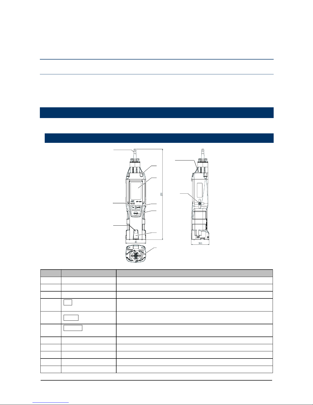
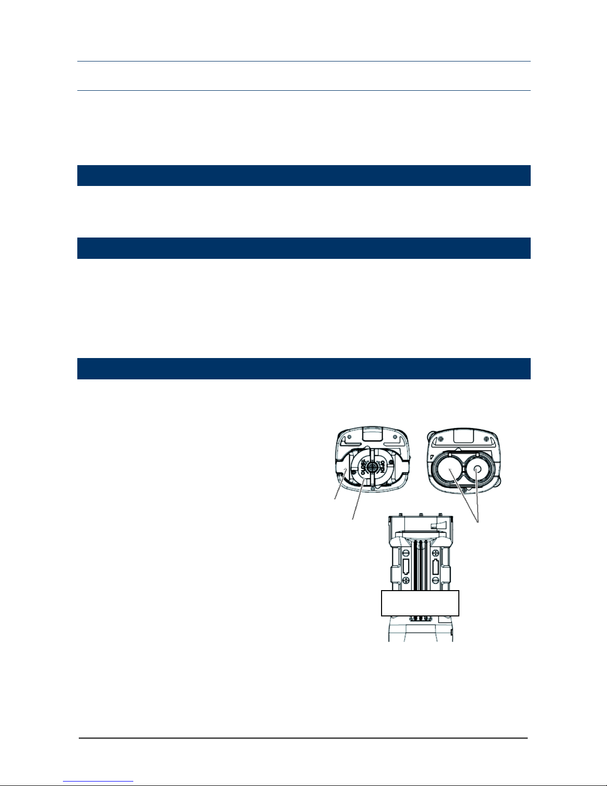
3-1. Names and functions for each part
This section describes names and functions of main unit, the battery unit parts, and the LCD display.
Main unit
No.
Name
Function
(1)
Gas inlet
Collects gas es.
(2)
Alarm LED arrays
Blinks or lights up in response to an alarm.
(3)
LCD display
Displays gas concentrations, measured gas name, alarms, etc.
(4)
AIR button
Keep this switch pressed to perform air calibration. Used to change the
screen and decrease numerical values in the setting mode.
(5)
MODE button
Press this switch to change between display modes. Used to change
the screen and increase numerical values in the setting mode.
(6)
POWER button
Turns the power ON or OFF . Used to change the screen and confirm
values in the setting mode.
(7)
Gas outlet
Exhausts the gas dr a wn in t o the detector. (Do not block it.)
(8)
Alarm LED arrays
Blinks or lights up in response to an alarm.
(9)
Infrared port
Used during inf ra r e d c om m un ications.
(10)
Battery cover
Protects the battery. Remove it to replace the batteries.
(11)
LED light
Provides you light for work.
(10)
(11)
(1)
(2)
(3)
(4)
(5)
(6)
(7)
(8)
(9)
Page 11
- 11 -
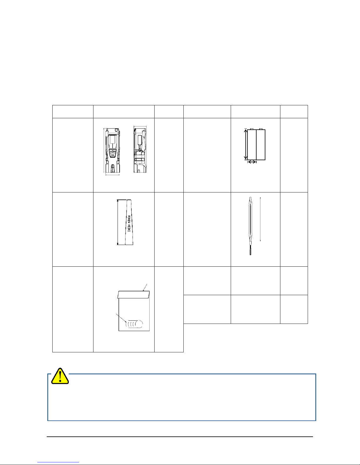
Standard accessories
Unpack and check the main unit and accessories.
• AA alkaline battery (2 pcs) ( ins tal l ed)
• Taper nozzle (1 pc)
• Rubber protec tion cover (1 pc) (Protect the detector from shocks by being hit, etc.)
• Hand strap (1 pc)
• Replacement hydrophobic filters (5 pcs)
• Product warra n t y ( 1 pc)
• Operating manual (1 pc)
Name
Appearance/
weight
Quantity Name
Appearance/
weight
Quantity
Rubber
protection
cover
1 pc
(attached)
AA
alkaline batt ery
2 pcs
(installed)
Taper nozzle
1 pc Hand strap
1 pc
Replacement
hydrophobic
filters
1 bag
(5 pcs
included)
Operating
manual
-
1 pc
Product
warranty
-
1 pc
If there is anything missing, contact RKI.
Approx. 9 g
Approx. 70 mm
Approx. 2 g
Approx. 150 mm
CAUTION
• Do not remove the panel sheet on the display. The water-proof and dus t-proof performances will
be deteriorated.
• Do not affix a label or the like on the infrared port. Infrared communications can no longer be
conducted.
Approx.
42 g
Approx. 44 g
Approx. 14.5 mm
Approx.
47mm
Approx. 42.5 mm
Approx. 149 mm
Approx. 50 mm
Approx. 1g
Approx.
φ16 mm
Plastic bag
Page 12
- 12 -
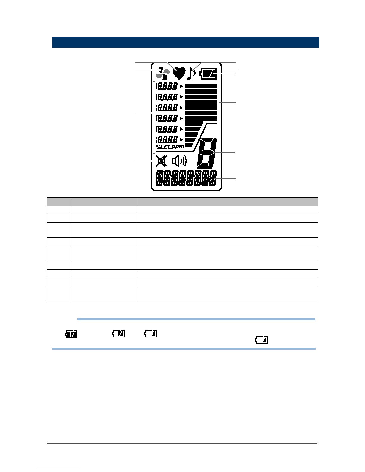
LCD display
No.
Name
Function
(1)
Operating state display
Displays the operating status in the detection mode. Normal: Blinking
(2)
Flow check display
Displays the drawing status. Normal: Rotating
(3)
Gas concentration
display
Displays gas concentration and units (ppm).
(4)
Alarm sound display
Displays the setting status of the alarm sound.
(5)
Operation sound
display
Displays the setting status of the operation sound.
(6)
Battery level icon
Displays a reference of the battery level.
(7)
Bar meter display
Displays the level of gas concentration in the form of a bar meter.
(8)
Mode display
Displays the measuring mode status.
(9)
Gas name and
message display
Displays the gas name and a message according to the function.
NOTE
• The meanings of bat tery level icons are as follows:
: Sufficient/ : Low/ : Needs replacement
If the batter y lev e l further drops, the insid e of the battery icon starts to bl i nk ( ).
(7)
(1)
(2)
(3)
(4)
(5)
(6)
(8)
(9)
Page 13
- 13 -
4
4. How to Use
4-1. Before using the detector
First-time users and user s wh o ha v e a lr ea dy used the detector must follow the operating precautions.
Ignoring the pr ec autions may damage t h e u n it, res u lt i ng in in ac curate gas measurement.
4-2. Preparation for start-up
Before use, read and understand the following precautions. Ignoring these may cause inaccurate gas
detection.
・ The batteries are installed (with sufficient battery level).
・ Check that the taper nozzle and filter are not contaminated.
・ Check that the taper nozzle is not bent or has no hole.
・ Check that the nipple to which the taper nozzle is attached is not loose.
4-3. How to replace the batteries
When the detector is used for the firs t t ime, or when the battery level is low, attach two new AA alkaline
batteries according to the following procedures.
1 Check that the power of the
detector is turned off.
Turn off the power if it is turned on.
2
Turn the lock plate
counterclockwise and open
the battery cover.
3
Remove old batteries and
then put new batteries
while observing the correct
polarity.
4
Close the battery cover and
tur n t he lock plate
clockwise to lock.
Battery cover
Lock plate
Dry batteries
Displaying batte ry
polarity
Page 14

- 14 -
CAUTION
• Never fail to turn off the power of the detector bef ore replacing the batteries.
• Replace the batteries in a safe plac e.
• Replace both of the two batteries with new ones at one time.
• Pay attention to the polarities during replacement. Replace while checking the battery polarities
stamped on the body.
• If the batter y cov er is not completel y locked, the dry batter ies m a y become dislodged or wa ter
may get in through the clearan ce. Wa ter may also get in if a minute forei gn sub stan ce is caugh t
between the detector and battery cover.
Page 15
- 15 -
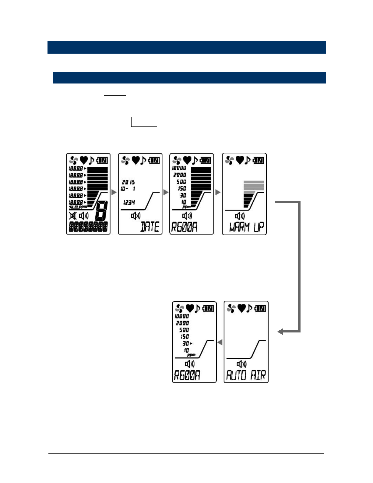
4-4. How to start the detector
When the power is t ur n ed on , a s e lf -diagnostic starts, and then the detector enters the detection mode.
Power-on
Press and hold th e POWER button until the buzzer blips (one second or longer) to turn o n th e po w e r.
When the power is t ur n ed on , th e LCD display chang es au tomatically as sho wn be l o w, and the detec t or
enters the detection mode.
1
Press and hold t he POWER button for one second or longer.
Hold it down until all the LCDs and alarm lamp light up and the buz zer bl ips.
All LCDs light
up
Date/time
display *
Gas name/
full scale display
Warm-up time
Display exam pl e:
Thursday,
October 01, 20 1 5
12:34
(Display for city
gases)
Detection mode
Automatic air
calibration
display
The buzzer blips
once and the
detection mode is
displayed.
* The date/time di s play i s d isp lay ed o nly when the clock fun cti on i s en abl ed . It i s no t displayed because the
clock function is disabled by default.
To enable the clock function, see "6-3. Clock function ON/OFF setting" on page 36.
Page 16

- 16 -
NOTE
• When powering on after leaving the detector for more than five minutes with the batteries removed,
such as when powering on for the first time, replacing the batteries, et c., or powering on with the
batteries inserted with incorrect polarities, a clock abnormality (FAIL CLOCK) may be triggered.
When it is reset using the MODE butto n, the detector moves to th e da t e /t ime setting screen. S ee
"6-2. Date/time setting" on page 35 and set the date/t ime.
• Warm-up time (WARM UP) is different depending on the stability status of the sensor.
• If the detector is not used for a long peri o d, war m-up time may be long er or a s en s or ab n or mality
(FAIL SENSOR) may be displayed. In such a case, restar t the detector.
• The detector performs air c al i br at io n a utomatically duri ng start-up. If an envir o nment where the
detector is tur ne d o n is d iffere nt from the atmosph ere being measured, perform air calibration again
in the measured atmosphere.
About LCD backlight
• Pressing the AIR, MODE or POWER button turns on the LCD backl i gh t. The LCD bac klight goes off
after 30 seconds of no operation.
When an alarm is tr ig g ered, the LCD backlig h t l ig hts up automatically.
Page 17
- 17 -
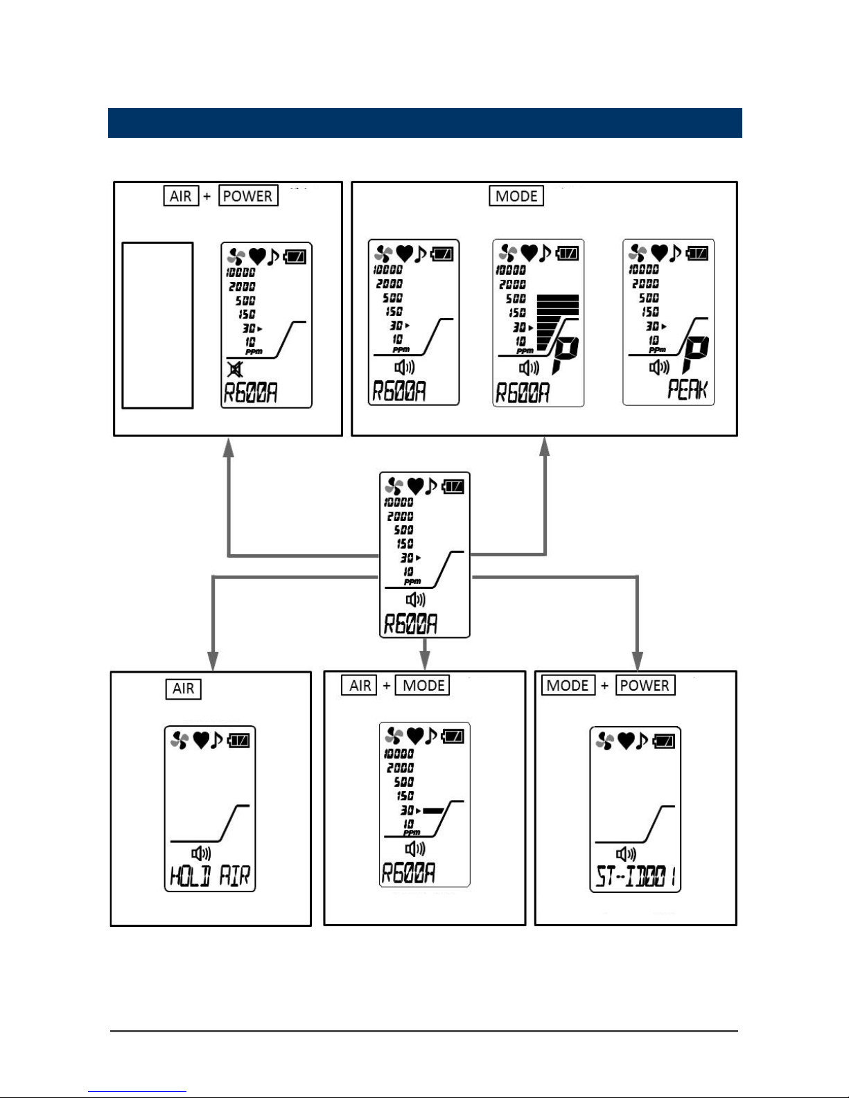
4-5. Basic operating procedures
The detectio n m od e is used after power-on. Gas is detected i n th e ppm range.
buttons
Hold down for
3 secs
Illumination
lamp lights
up
button
Hold down for
1 sec
Hold down for
3 secs
button
buttons
buttons
Hold down for 3 secs
<AIR calibration>
<Alarm setpoint change>
<Snap logger record>
<Operation/alarm sound ON/OFF>
<Peak clear> <Peak hold ON/OFF> <Display mode>
* Displayed only when the clock
function is enabled
See "6-3. Clock function ON/OFF
setting" on page 36.
Page 18
- 18 -
4-6. How to detect
While the detector is ope rati ng in det e ction mode , put th e tip o f the ta pe r nozz le clo se to the det e cti on area
and draw sample.
The detector measures gas in the ppm range. If a gas is drawn, the detected gas concentration is
displayed with the bar meter on the LCD display.
CAUTION
• Before performing gas detection , at tac h th e ta p er no z z le pro v i de d wi t h th e detector to preve nt
disturbances by air dust.
DANGER
• While conducting measurement in a manhole or confined space, do not lean over or look into
the manhole or closed space. It may lead to dangers because oxygen-deficient air or other
gases may blow ou t.
• Oxygen-deficient air or oth er gases may be discharg e d f rom the gas exhaustin g ou t le t of the
detector. Never inhale t he air or gases.
• High-concentration (100% LEL or higher) combustible gases may be discharged from the gas
exhausting o ut l et of th e de tector. Never use fire near it.
WARNING
• The detector is designed to draw gases around it under the atmospheric pressure. If excessive
pressure is applied to the gas inlet and outlet of the detector, detected gases may leak out from
its inside and may cause dangerous conditions. Be sure that excessive pressure is not applied
to the detector while used.
• When performing an air calibrati o n, v erify that you are in a fr es h a ir en v ir onment before
starting. If interference gases or other gases exist, the adjustment cannot be performed
properly, thus leading to dangers when the gas leaks.
• Issuance of a gas alarm indicates t ha t th er e are ex tr e me dangers. Take proper acti ons based
on your judgment.
• Before use, check that there remains sufficient battery power . When the detector is not used for
a long period, the batteries may be exhausted. Never fail to replace them with new ones before
use.
• If a low battery alarm is triggered, gas detection cannot be conducted. If the alarm is triggered
during use, turn off the power and promptl y replace the batteries i n a safe area.
• Do not block the buzzer sound opening. No alarm sound can be heard.
• If the main unit is dropped or given a shock, the reading may rise and it may remain so. In such
a case, perform air calibration in a place where the surrounding air is fresh.
Page 19

- 19 -
4-7. Changing the concentration measuring mode
In the detector, the detection gas type is factory set to R600a (Isobutane) and the alarm setpoint is factory
set to 30 ppm.
The detector has 5 preset alarm setpoints that the user can cycle through (10 ppm, 30 ppm, 150 ppm, 500
ppm, and 20 0 0 ppm).
For the measuring mode, the concentration measuring mode or differential measuring mode can be
selected.
<Concentration measuring mode>
Perform air calibration in the atmosphere.
Then, the mode monitors chang e s to the air value , showin g the co rrelation between a leakage amount and
the bar display.
(If the measured atmosphere changes, perform air calibration again.)
<Differential measuring mode>
Perform automatic air calibration at regular intervals in the atmosphere of measurement environment. This
is a high sensitivity mode that ena ble s detection of ultralow amounts of leaking gas in the air by eliminating
the environmental effects (other gases, temperature and humidity). Since it can detect a slight amount of
increase in gas concentration even in th e en vironment where a gas is l eaking already, this measuring
mode is effective to identify a leakin g po i nt .
In the differential measuring mode, "LOW MODE"(low sensitivity) and "HIGH MODE"(high sensitivity) can
be switched. When the detector cannot detect gas leakage in “LOW MODE”, switching to “HIGH MODE”
will allow detection of an ultralow gas leak.
Gas alarm setpoint for concentration measuring mode
1
In the detection m ode, press the AIR and MODE buttons at the same time.
The alarm setpoint is changed to the next pre-defined setpoint every time the AIR and MODE buttons
are pressed. There are 5 setpoints t otal , a ll in the ppm range.
NOTE
• The alarm setpoint cannot be set to 10000 ppm.
Page 20

- 20 -
Gas alarm setpoint for differential measuring mode
1
In the detection mode, press the AIR and MODE buttons at t he same time.
The alarm setpoint is chan ge d to the next pre-defined setpoint every time the AIR and MODE buttons
are pressed. There are 6 setpoints t otal .
Changing the gas alarm sensitivity for differential measuring
mode
1
In the detection mode, press the AIR button.
The alarm sensitivity changes from LOW MODE to HIGH MODE every time the AIR butt on is pr es sed.
Page 21

- 21 -
NOTE
• For switching to the differential measuring mode, see "Change of the measuring mode" in the display
mode on page 31.
CAUTION
• Performing an air c a libration in the prese nc e of gas will decrease th e bar meter.
• For excessiv e temperature/hum id ity changes, the bar meter may increase.
• When the mode is switched from the differential mode to the concentration measuring mode,
check the atmosphere for freshness and perform air calibration again in the measured
atmosphere.
• The gas concentrati on is displayed in six levels (without a unit).
• Air calibration is performed automatically and it cannot be performed manually.
Page 22
- 22 -
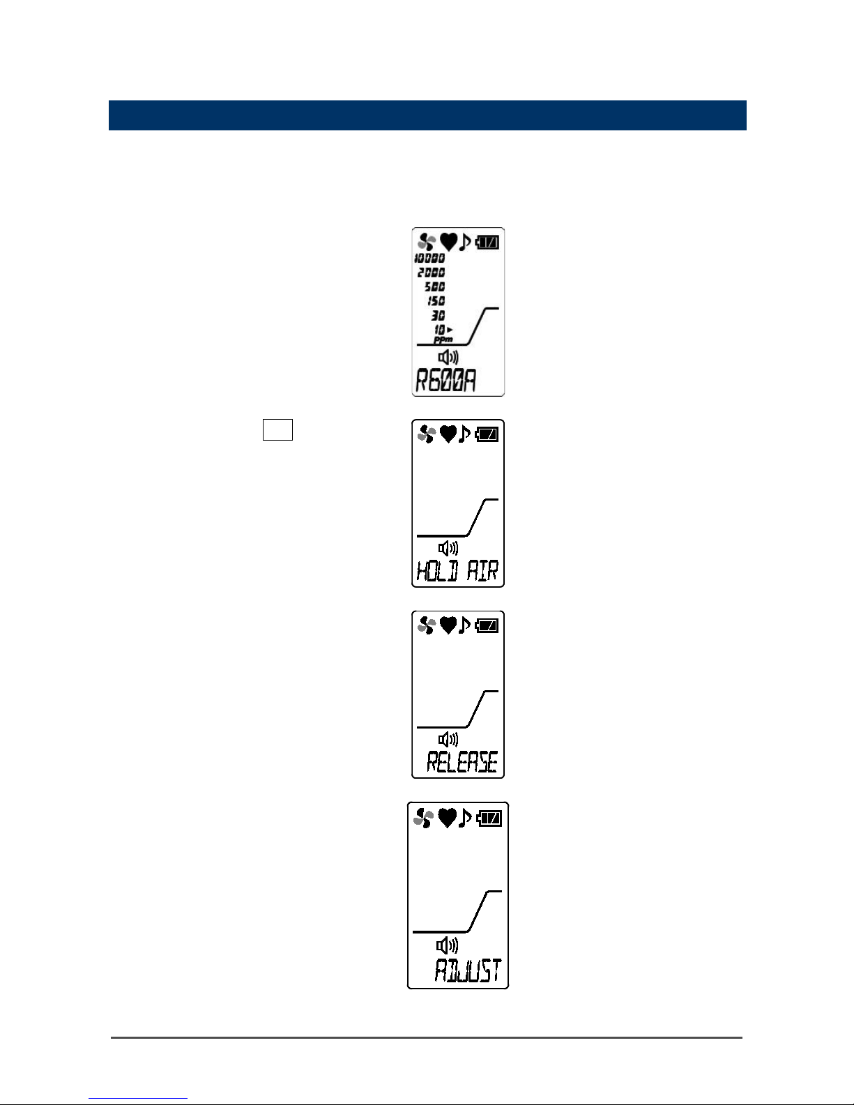
4-8. Performing air calibration
After a high-concentration gas is detected or an alarm is triggered by temperature/humidity changes,
perform air calibration in the measured atmosphere.
* Before performing air calibration, verify a fresh air enviro nment.
1
In the detection m ode,
hold down the AIR button.
2
Release the AIR button
when the display
changes from "HOLD
AIR" to "RELEASE".
(Buzzer sound: Three times <blip,
blip, blip>)
▼
▼
The air calibra t io n is d on e an d th e
detector returns to detection
mode.
(Buzzer sound: Once < blip>)
If air calibration fails, "FAIL AIR
CAL" is displayed.
Perform air calibration aga i n i n
fresh surrounding air.
Page 23

- 23 -
NOTE
• Perform air calibration under pressure and temperature/humidity conditions close to those in the
operating environment and in fresh air.
• Perform air calibr ation after the readi ng is stabilized.
• If there is a sudden temperature change between the storage and operational locations, turn on the
power of the detector, let it stand for five minutes or more in a similar environment to the operational
location, and perform air calibration in fresh air before using it.
4-9. Snap logger
Any peak value during measurement can be recorded.
Up to 256 points of data can be recorded. When the number of recorded data points reaches the maximum,
recorded data will be overwritten, starting from the oldest data.
This function is enabled when the clock function is enabled. Since the clock function is disabled by default,
enable it before using the snap logger function (See "6-3. Clock function ON/OFF setting" on page 36).
1
In the detection m ode,
press the MODE and
POWER buttons at the
same time.
The detector enters the station ID
selection screen.
2
Use the MODE or AIR
button to select the
station ID and pres s the
POWER button.
The peak value is d is pl ayed.
To stop recording, press the
AIR and MODE buttons at the
same time. The detector
returns to the detection mode.
3
Press the POWER button.
The date/time and peak value are
recorded.
To continue recording the log,
repeat steps 2 to 3.
To stop recording the log, press
the AIR and MODE buttons at
the same time. The detector
returns to the detection mode.
NOTE
• The recorded data c an be r ea d o ut by the "Data Logger Mana gement Program" (o pt i on a l) . S e e th e
operating manual of "Data Logger Management Program" for more information.
Page 24

- 24 -
4-10. Peak hold function
When the peak hold function is enabled, the latest peak value is always displayed with the bar meter.
1
In the detection
mode, hold down the
MODE button (for
three seconds or
longer).
The peak hold function is
enabled. While the peak
hold function is enabled, "P"
is displayed on the LCD
display.
To disable the peak hold
function, hol d do wn the
MODE button for three
seconds or longer.
NOTE
• To clear a retained peak value, hold down the MODE button (for one second) in the detection mode.
4-11. Changing the alarm and operation sounds
Turn the alarm and operation sounds ON or OFF.
1
In the detection mode, press the AIR and POWER buttons at the same time.
The settings for the alarm and operation sounds are switched every time the AIR and POWER buttons
are pressed.
Alarm sound ON
Operation sound ON
Alarm sound OFF
Operation sound ON
Alarm sound OFF
Operation sound OF F
Alarm sound ON
Operation sound OF F
Page 25

- 25 -
4-12. How to turn on the illumination lamp
The illumination lamp can be turned on, if necessary.
1
Hold down the AIR and POWER buttons at the same time (for three
seconds or longer).
The illuminat i on lamp lights up. The illumination lamp will aut omatically go off two minutes after it
lights up.
To turn off the illumination lamp, hold down the AIR and POWER buttons at the same time (for three
seconds or longer).
4-13. Power-off
Press and hold the POWER button (at least three seconds) until the buzzer blips three times ("TURN OFF"
disappears) to turn off the power.
CAUTION
• If a gas remains in the detector, it enters the automatic exhaust mode (for a maximum of 30
seconds). How e v e r, the detector is t ur n ed off after t he au tomatic exhaust m ode . The mode
counts down from automatic exhaust start (PURGE 30). The detector switches to the "TURN
OFF" display when the gas exhaust is completed and is turned off.
Automatic exhaust start (PURGE 30)
Page 26

- 26 -
5
5. Display Mode
5-1. Enteri ng the displ ay mode
This mode allows users to view and change various display settings and perform other operation.
(Display example: For city gases)
1
In the detection m ode, press the
MODE button.
The detector enters the peak value display in the
display mode.
2
Next, press the MODE butto n to
display the appropriate menu.
The setting screen for the display mode is
switched every time the button is pr ess e d.
Holding down the button also switches the
setting screen. When the detector returns to the
detection mode, the setting screen stops being
switched.
3
Select the setting item and press
the POWER button.
For setting items, see "Display mode overview"
on page 27.
NOTE
• The detector automatically returns to the detection mode in about 20 seconds if the detector is left
unoperated.
• Gas detection is continued in the display mode and an al arm can be activated.
Page 27

- 27 -
Display mode overview
Item
LCD display
Details
Peak display
Displays the maximum concentration
detected dur in g th e p eriod from power-on
to the point of checking.
* To clear the peak display, hold down the
AIR button until "PEAK CLR" is
displayed.
Measured gas reading
setting
By changing the setting to the
pre-registe re d gas in the detector, the
converted concentration from the
detection targe t g as wi l l b e dis p layed.
(P. 29)
Measuring mode setting
Changes (in small measure) the pump
suction volume by mode changing the
measuring mode (in the differential
measuring mode the pump suction
volume is up).
(P. 31)
* NORMAL (Concentration measuring
mode)
DIFF (Differential measuring mode)
Log data display
Displays the data recorded by the snap
logger. (P. 32)
* Displayed only when the clock function
is enabled
See "6-3. Clock function ON/OFF
setting" on page 36.
Page 28

- 28 -
Entering user mode
Enters the user mode.
(P. 33)
Detection mode
Returns to the detection mode.
Page 29

- 29 -
5-2. Measured gas reading setting
Normally, the concentration display of the detector is "Isobutane (R600a)" depending on the specification;
however, a pre-registered gas can be read instead to detect its concentration.
1
On the "GAS LIST"
screen in the display
mode, press the POWER
button.
The detector enters the gas
reading setting.
▼
The currently set gas name is
displayed.
2
Press the MODE or AIR
button to select a gas
name to be read
instead.
The gas name switches to
another every time the button is
pressed.
3
When the target gas
name is displayed,
press the POWER
button.
"END" is displayed, returning to
the display mode.
Page 30

- 30 -
Note
・ To perform the concentration displayed gas reading setting, see the "Gas list" in the following page.
Gas list
Gas name
(standard name)
Display
Grid 1
(ppm)
Grid 2
(ppm)
Grid 3
(ppm)
Grid 4
(ppm)
Grid 5
(ppm)
Grid 6
(ppm)
Unit
conversion
【
Only as a guide】
(g/year)
R600a(Isobutane) R600A 10 30 150 500 2000 10000 Approx.2.7
R290(Propane) R290 10 50 200 500 2000 10000 Approx.2.1
R123 R123 20 100 500 2000 5000 10000 Approx.14.4
R134a R134A 20 100 500 2000 5000 10000 Approx.9.58
R142b R142B 10 50 100 200 500 1000 Approx.4.7
R22 R22 10 50 200 1000 3000 10000 Approx.4.1
R32 R32 10 50 200 500 2000 10000 Approx.2.4
R23 R23 10 50 200 500 2000 5000 Approx.3.3
R407C R407C 10 50 200 500 2000 10000 Approx.4.0
R410A R410A 10 50 200 500 2000 10000 Approx.3.4
R404A R404A 10 50 200 500 2000 5000 Approx.4.6
2,3,3,3-Tetrafluoro
propene
(HFO-1234yf)
R1234YF 10 50 200 500 1000 2000 Approx.5.3
R507A R507A 10 50 200 500 1000 2000 Approx.4.6
R407A R407A 10 50 200 500 2000 5000 Approx.4.2
Alarm setting can be changed in five levels among grid 1 to 5.
Note
• Unit conversi o n is estimated value wh e n it ass umed as pump flow rate is approx. 20m l/min and
steady and measured by “Grid 1”.
The actual conversion value is affected by the age of the pump and varies from pump to pump.
• High-concentration or continuous contact with a chloride or sulfur compound will shorten the sensor
life or cause larger errors.
• If a Si compound is detected, the sensitivity will decrease.
• If a high-concentration so lv en t gas is drawn, the rubb e r se a l us e d i n th e d et ec t or wi l l deteriorate.
Page 31

- 31 -
5-3. Changing the me asu r ing mode
The measuring mode of the detector (for fumigation gases) can be switched from "concentration measuring
mode" to "differential measuring mode", where lower concentration detection can be conducted.
1
On the "MODE CHG"
screen in the display mode,
press the POWER button.
The detector enters the setting
to switch the measuring mode.
2
Press the MODE or AIR
button to select the
measuring mode.
The measuring mode switches
to the other every time the
button is press e d.
<Concentration measuring
mode>
<Differential
measuring mode>
3
In the appropriate
measuring mode, press the
POWER button.
"END" is displayed, returning to
the display mode.
Page 32

- 32 -
5-4. Log data display
The data recorded by the snap logger can be viewed.
The "REC DATA" screen is displayed only when the clock function is enabled (See "6-3. Clock function
ON/OFF setting" on page 36).
1
On the "REC DATA"
screen in the display
mode, press the POWER
button.
The detector enters the log data
display.
The recorded date/time is
displayed and the station ID and
memory number are displayed
alternately. If there is no
recorded data, "NO DATA" is
displayed.
* When there is no r ec or d ed data
2
Press the MODE or AIR
button to select log
data to be displayed.
The recorded content switches
to the other every time the
button is press e d.
<Station ID> <Memory number>
3
When the target log
data is displayed, press
the POWER button.
The gas name and peak value
of the selected memory are
displayed alternately.
4
To exit the display,
press the MODE and
AIR buttons at the same
time.
The detector returns to the
display mode.
Page 33

- 33 -
6
6. User Mode
6-1. Enteri ng the user mode
The maintenance including internal clock correction, etc. can be performed.
1
In the detection m ode, press the
MODE button a few times to display
"USER" and then press the POWER
button.
The detector enters the date/time setting in the
user mode.
2
Next, press the MODE or AIR button
to display the appropriate menu.
The setting screen for the user mode switches to
another every time the button is pres s ed.
3
Select the setting item and press
the POWER button.
For setting items, see "User mode overview" on
page 34.
CAUTION
• Return to the detection mode after use.
Page 34

- 34 -
User mode overview
Item
LCD display
Details
Date/time setting
Set the date/time of the internal clock.
(P. 35)
* When the clock function is disabled, the
date/time setting screen is not
displayed.
Clock function ON/OFF
setting
Enable or disable the clock function.
ROM/SUM display
Displays the program number and SUM
value of the detector.
* This is not typical ly used by the user.
Entering detection mode
To exit the user mode, press the POWER
button to enter th e d et ec t i o n m od e.
Page 35

- 35 -
6-2. Date/time setting
Set the date/time of the internal clock.
The date/time setting screen is displayed only when the clock function is enabled. Enable the clock function
in "6-3. Clock function ON/OFF setting" on page 36 before setting the date/time.
1
On the "DATE" screen in th e user
mode, press the POWER button.
The detector enters the date/time setting.
2
Press the MODE or AIR button, s et
the date/time and press the POWER
button.
3
Set year -> month -> day -> ho ur ->
minute in this order.
When the "minute" value is confirmed, "END" is
displayed an d t he n th e d et ec t or returns to the
user mode menu.
Page 36

- 36 -
6-3. Clock function ON/OFF setting
Enable or disable the clock function.
The clock function is disabled by default. If the date/time needs to be displayed on start-up or the snap logger
function is used, enable the clock function.
1
On the "CLOCK" screen in the user
mode, press the POWER button.
2
Press the MODE or AIR button to
display the desired setting (ON/OFF)
and press the POWER button to
confirm it.
3
Setting completed
After the clock function ON/OFF setting is
completed, "END" is displayed and then the
detector returns to the user mode menu.
NOTE
• When the clock function is changed from disabled to enabled, a clock abnormality (FAIL CLOCK)
may be triggered if the date/time is inaccurate. When the failure condition is rese t usi n g the MODE
button, the detector moves to the date/time setting screen. Set the dat e/ time in acc ordance with
"6-2. Date/time setting" on page 31.
• When the clock function is changed from disabled to enabled for the
first time, powered on after leaving the detector for more than five minutes
with the batteries removed, or po wered on with the batter i es ins er t e d wi th
incorrect polarities, a clock abnormality (FAIL CLOCK) may be triggered.
Page 37

- 37 -
7
7. Alarm Function
7-1. Gas alarm activation
When the conce ntration of detected g as r eac hes or exceeds the ala r m setpoint values, a "g as a larm" is
triggered in the detector. The alarm lamp blinks, the buzzer sounds, and the bar meter display indicates an
alarm condition. (Auto-res e t op er a t io n)
Blinking alarm lamp and buzzer sound operation for gas alarms have different intervals depending on the
detected concentration.
7-2. Fault alarm activation
"Fault alarm" i s tri gge red using a buz z er so und and bl in king alarm lamp when an abnormality is detected in
the detector. (Self-latching)
When an alarm is trigge red, one of the following fault details is displayed on the LCD.
- System
abnormalities
: FAIL SYSTEM
- Battery voltage
low
: FAIL BATTERY
- Calibration
abnormalities
: FAIL AIR CAL
- Clock
abnormalities
: FAIL CLOCK
- Low flow rate
: FAIL LOW FLOW
- Pump
abnormalities
: FAIL PUMP
- Sensor
abnormalities
: FAIL SENSOR
Alarm lamp
Repeatedly blinks at about one-second intervals.
Buzzer
Repeatedly sounds intermittent bee ps at ab out
one-second intervals.
Blip-blip, blip-blip
LCD display
Display example of low flow rate (LOW FLOW)
If a fault alarm is triggered, refer to trouble shooting and take appropriate action.
If the unit has problems and is repeatedly malfunctioning, contact RKI immediate l y.
NOTE
• The low flow rate alarm (FAIL LOW FLOW), calibration abnormalities (AIL AIR CL) and clock
abnormalities (FAIL CLOCK) can be reset by pressing the MODE button.
• For informati o n on m alf u nc t io ns (er ror messages), see "Troubleshooting" on page 45.
Page 38

- 38 -
8
8. Maintenance
The detector is a precision d e v ice.
To maintain the performance of the detector and improve the reliability of detecting leak ag e, perform a
regular maintenance.
8-1. Maintenance interva ls and item s
Perform the following maintenance regularly before use.
・ Daily maint e na nc e : P er f o r m maintenance befor e commencing each wor k.
・ Monthly maintenance: Perform alarm test once a month.
・ Regular maintenance: Perform maintenance once or more for one year to maintain the performance as a
unit.
Maintenance
item
Maintenance content
Daily
maintenance
Monthly
maintenance
Regular
maintenance
Battery level
check
Check that the battery level is
sufficient.
○ ○ ○
Concentration
display check
Make the detector draw in fresh air
and check that the concentration
display valu e is ze r o . When the
reading is incorrect, perform zero
adjustment by air calibration after
ensuring that no other gases exist
around it.
○ ○ ○
Flow rate
check
Check the flow check display to find
abnormalities.
○ ○ ○
Filter check
Check the dust filter for dust or
clogging.
○ ○ ○
Gas alarm
calibration
Check the gas al arm using a
calibration g as .
- - ○
Page 39

- 39 -
About maintenance services
We provide services on regular maintenance including span adjustment, other a dj ustments and
maintenance.
Our qualified ser v ice engineers have ex p ertise, knowledge an d other informatio n on th e d edicated tools
used for services, along with other products. To maintain the safety operation of the unit, pl ease use our
maintenance service.
The followings are typical maintenance services. For details, contact RKI.
<Main Services>
Item
Services
Battery level
check
Checks the battery level.
Concentration
display check
Verifies that the concentration display value is zero by using the zero gas.
Performs the air calibration if the reading is incorrect.
Flow rate check
Checks the flow rate indicator to find abnormalities.
Checks the flow rate by using an external flow meter to verify the correctness of the
flow rate indicator on the detector. If the flow rate is incorrect, performs the flow rate
adjustment.
Filter check
Checks the dust filter for dust or clogging.
Replaces a dirty or clogged dust filter.
Span
adjustment
Performs span adjustment using a ca li bration gas.
Cleaning and
repair of the unit
(visual
diagnosis)
Checks dust or damage on the surface of the unit, cleans and repairs such parts.
Replaces parts whic h ar e cr ac ked or damaged.
Unit operation
check
Operates the buttons to check the operation of functi o ns an d par ameters, etc.
Replacement of
consumable
parts
Replaces consumable parts, such as a sensor, filter, pump, etc.
Page 40

- 40 -
8-2. How to clean
Clean the detec t or if i t becomes extreme l y dirty. The detector must be turned off while clean i n g it . Us e a
waste cloth or the like to remove dust. Do not use water or organic solvent for cleaning because they may
cause malfunctions.
Because an extremely contaminated inside of the taper nozzle may disturb the gas detection, it must be
cleaned with dry air, etc.
NOTE
• When the detector gets wet, water may remain in the buzzer sound opening or grooves. Drain water
as follows:
(1) Wipe away moisture on the detector thoroughly using a dry towel, cloth, etc.
(2) While holding the detector firmly, shake it about ten times with the buzzer sound opening facing
downward.
(3) Wipe away moisture coming out from the inside thoroughly using a towel, cloth, etc.
(4) Place the det ec t or o n a dry towel, cloth, etc. an d let it stand at normal tem peratures.
8-3. Parts replacement
Hydrophobic filter replacement procedure
Continuing to use the detector may cause the hydrophobic filter to be contaminated or clogged.
Replace the hydrophobic filter if it becomes extremely dirty.
Also, replace the hydrophobic filte r wh en it has absorb ed water or has a lower flow r at e.
1
Turn the cap co unterclockwise and
remove it.
2
Remove the rubber seal from the cap.
The hydrophobic filter is instal led in
the rub ber seal.
CAUTION
• When cleanin g t he det ec t or, do not splas h water over it or use org an ic s o l ve nts su c h as
alcohol, benzene, etc. on it. Otherwise, it may cause discoloration or damage to the surface of
the detector or a sensor failure.
Cap
Rubber seal
Page 41

- 41 -
3
Replace the hydrophobic filter with a
new one. Make sure it’s seated in the
rubber seal correctly.
4
Attach the rubber seal, with the filter
installed, to the cap.
Make sure the rubber seal’s rib has been firmly
inserted into t h e cap’s groove.
5
Attach the cap, with the rubber seal
attached, to the main unit.
Hydrophobic
Filter
Rubber seal
Rib
Groove
Page 42

- 42 -
Sensor replacement
The sensor comes with a 1-year warr an t y. It has a typical life of 2-3 years, depen di n g on th e op erating
environment. The sensor life has expired if, for example, the reading fluctuates or does not respon d during
calibration. Contact RKI for sensor replacement.
Battery replacement
For battery re p lac ement, see "How to rep lac e the batteries" on page 13.
Page 43

- 43 -
9
9. Calibr ation Mode
This section describes how to perform a fresh air adjustment, an automatic span adjustment, and a manual
span adjustmen t on the SP-220. It also describes how to turn on the Calibration Mode password function.
9-1. Fresh Air Adjustment
RKI Instrumen ts, I nc . r ec ommends that the fr es h air a dj us tment be performed in a fresh air area (area
known to be free of t ox ic a nd combustible gases an d of nor mal oxygen conten t, 20 .9 % ). If a fresh air
environment is not available, a cylinder of zero air can be used as long as the gas is applied through a
humidifier tube. Calibration kits for the SP-220 do not normally include zero a ir or a humidifier tube.
1
Be sure the SP-220
has been running in
Detection Mode for
at least 10 minutes
before continui ng.
2
With the ins t rument
running i n Detection
Mode, press and hold
the AIR and MODE
buttons for 3
seconds.
3
If the Calibration
Mode password
parameter ha s been
set to on (factory
setting is off), you
will be prompt ed for
a password.
Use the AIR and
MODE buttons to
adjust each
character and press
the POWER button to
move to the next
character.
Page 44

- 44 -
4
The AIR C AL menu
item will be
displayed.
5
Press and release
the POWER button.
6
Make sure you are in
a fresh air area (area
known to be free of
toxic and
combustible gases
and of normal
oxygen content,
20.9%).
7
Press and hold t he
AIR button. Release
the AIR button whe n
the screen says
“RELEASE”.
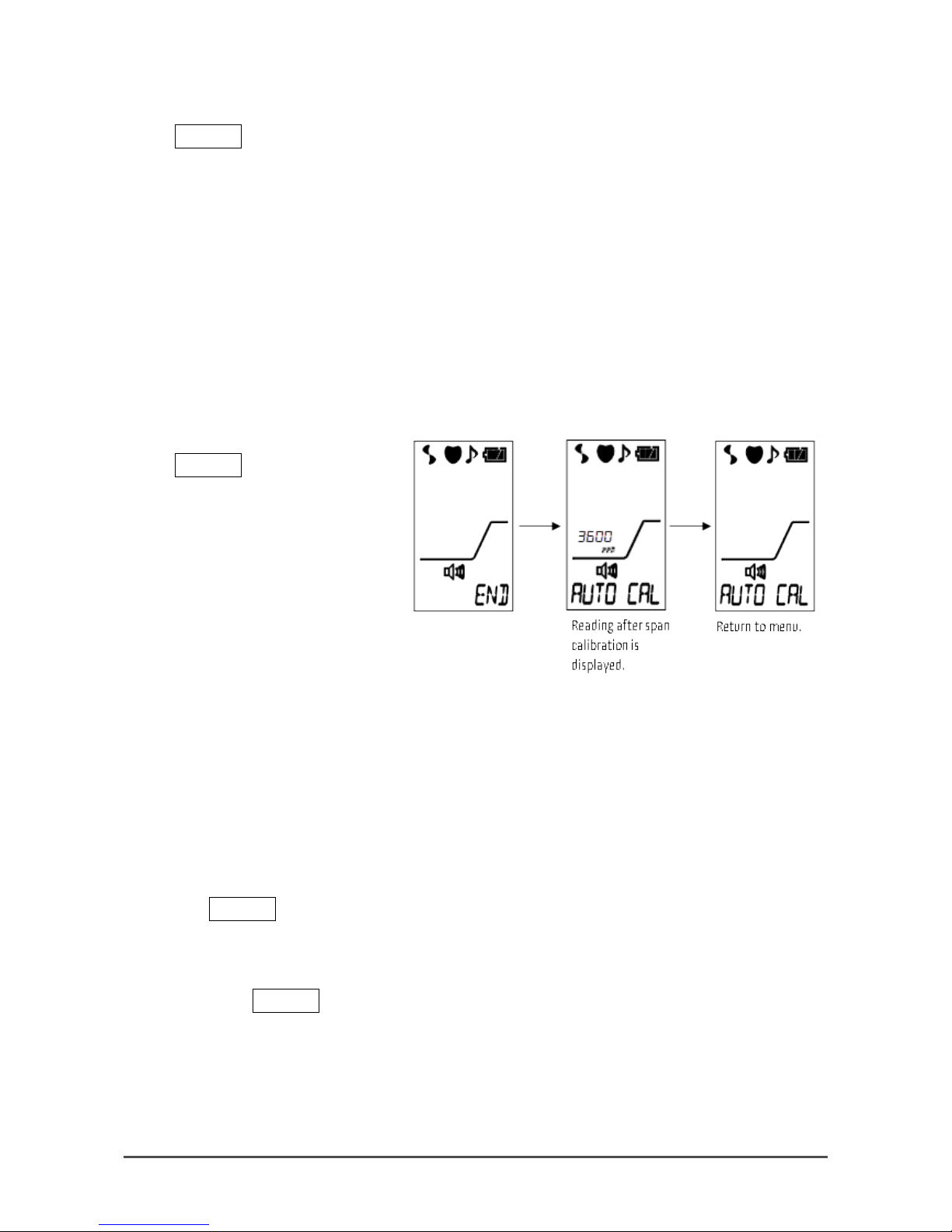
8
The instrument will
perform a f resh air
adjustment and will
return to the AIR
CAL menu item.
Page 45

- 45 -
9
See the following
sections for span
adjustment
descriptions.
To return to
Detection Mode
without performing a
span adjustment,
scroll to the
MEASURE menu
item and press and
release the POWER
button.
To turn the
instrument off, press
and hold the POWER.
9-2. Preparing for a Span Adjustment (Gas Bag)
This section describes how to prepare for calibration if you are using a calibration kit that includes:
• Gas bag with a tub in g clamp
• Fixed flow regulator
• Calibration cylinder
1. Empty the gas bag.
2. Connect the bag’s tubing to the fixed flow regulator’s hose barb fitting.
3. Screw the fixed flow regulator onto the calibration cylinder.
4. If your regulator has a knob, turn the knob counterc l ockwise to start the flo w of ga s into t h e g as ba g.
5. Allow the gas to dispense until the gas bag is a little over half full.
6. If your regulator has a knob, turn the knob clockwise to stop the flow of gas.
7. Clamp the gas bag tubing shut.
8. Remove the tubing from the fixed flow regulator’s hose barb fitting.
9. Remove the fixed flow regulator from the calibration cylinder.
Page 46

- 46 -
9-3. Preparing for a Span Adjustment (Demand Flow
Regulator)
This section describes how to prepare for calibration if you are using a calibration kit that includes:
• Demand flow regulator
• Calibration tubing
• Calibration cylinder
1. Screw the demand flow regulator onto the calibration cylinder.
2. Connect the tubing to the demand flow regulator’s hose barb fitting.
9-4. Automatic Span Adjustment
These instructions describe an automatic calibration of the SP-220. Be sure you have performed a fresh air
adjustment and prepared for calibration as described in the previous sections before continuing.
1
If you have just
perform ed a fresh air
adjustment and the
instrument is still
running i n Calibration
Mode, continue to step
5.
If your i ns t rument is not
currently running in
Calibration Mode,
continue to step 2.
2 With t he instrument
running i n Detection
Mode, press an d hold
the AIR and MODE
buttons for 3 seconds .
3
If the Calibration Mode
password parameter
has been set to on
(factory setting is off),
you will be prompted for
a password.
Page 47

- 47 -
Use the AIR and MODE
buttons to adjust each
character and press the
POWER button to move
to the next character.
4
The AIR C AL menu item
will be displayed.
5
Use the AIR or MODE
button to scrol l to the
AUTO CAL menu item.
6
Press and release the
POWER button. The auto
cal value will be
displayed.
7
To adjust the aut o cal
value:
a. Press and hold the
MODE button then
press and hold the
POWER button. The
auto cal value will
begin to flash.
b. Use the AIR and
MODE buttons to
adjust the value.
c. Press t he POWER
button to confirm the
change.
Page 48
- 48 -
8
Press and release the
POWER butt on. T h e gas
reading will begin to
flash.
9
Apply calibration gas for
1 minute.
Depending on your calibration
kit, you will need to either:
a. Connect the gas bag
tubing to the
instrument’s inlet or
b. Connect the tubing
from the demand flow
regulator to the
instrument’s inlet.
10
Press and release the
POWER butt on. T h e
instrument will perform
a gas adjustment and
will return to the AUTO
CAL menu item.
11
Disconnect the
calibration gas source
from the instrument’s
inlet fitting.
12
To enter Detection
Mode, scroll t o the
MEASURE menu item
and press and release
the POWER button.
To turn off the
instrument, press and
hold the POWER button.
Page 49

- 49 -
9-5. Manual Span Adjustment
These instructions describe a manual calibration of the SP-220. B e s ur e you h a ve per f or med a fresh air
adjustment and prepared for calibration as described in the previous sections before continuing.
1
If you have just
perform ed a fresh air
adjustment and the
instrument is still
running i n Calibration
Mode, continue to step
5.
If your i ns t rument is
not currently running in
Calibration Mode,
continue to step 2.
2
With the ins t rument
running i n Detection
Mode, press an d hold
the AIR and MODE
buttons for 3 seconds .
3
If the Calibration Mode
password parameter
has been set to on
(factory setting is off),
you will be prompted
for a password.
Use the AIR and MODE
buttons to adjust each
character and press the
POWER button to move
to the next character.
4 The AIR CAL menu item
will be displayed.
Page 50

- 50 -
5
Use the AIR or MODE
button to scrol l to the
MANU_CAL menu item.
6
Press and release the
POWER button. The gas
reading will begin to
flash.
7
Apply calibration gas
for 1 minute.
Depending on your
calibration kit, you wil l need
to either:
a. Connect the gas bag
tubing to the
instrument’s inlet or
b. Connect the tubing
from the demand flow
regulator to the
instrument’s inlet.
8
Use the AIR and MODE
buttons to adjust the
gas reading t o m atch
the value listed on the
calibration cylinder.
9
Press and release the
POWER butt on. T h e
instrument will perform
a gas adjustment and
will return to the
MANU_CAL menu item.
Page 51

- 51 -
10
Disconnect the
calibration gas source
from the instrument’s
inlet fitting.
11 To enter Detection
Mode, scroll t o the
MEASURE menu item
and press and release
the POWER button.
To turn off the
instrument, press and
hold the POWER button.
9-6. Password
These instructions describe how to turn the Calibration Mode password on or off and how to set the
password.
1
If your i ns t rument is
still running in
Calibration Mode,
continue to step 4.
If your i ns t rument is
not currently running in
Calibration Mode,
continue to step 2.
2
With the ins t rument
running i n Detection
Mode, press an d hold
the AIR and MODE
buttons for 3 seconds .
Page 52

- 52 -
3
The AIR CAL menu item
will be displayed.
4
Use the AIR or MODE
button to scrol l to the
PASSWORD menu item.
5
Press and release the
POWER butt on. T h e
current setting will be
displayed.
6
Use the AIR or MODE
button to adjust the
on/off setting. If the
password is set to on, a
user-defined password
will be required to enter
Calibration Mode.
7
Press and release the
POWER button.
If you set the password
function to off,
continue to step 9.
If you set t he password
function to on, continue
to step 8.
8
Use the AIR or MODE
button to adjust the
first number in the
desired password.
Press and release the
POWER button to move
on to the next
character and the n
save the password.
Page 53

- 53 -
9
To enter Detection
Mode, scroll t o the
MEASURE menu item
and press and release
the POWER button.
To turn off the
instrument, press and
hold the POWER button.
Page 54

- 54 -
10
9. Storage and Disposal
10-1. Procedures to store the detector or leave it for a
long time
The detector must be stored under the following environmental conditions.
• In a dark place under the normal temperature and humidity away from direct sunlight
• In a place where g as es, solvents, vapors, e tc . are not present
Store the detector in a shi p pi n g car t on , if any, in which the pro duct was delivered.
Store the detector away from dust, etc. if the sh ip p i ng c arton is not availabl e.
10-2. Procedures to use the detector again
CAUTION
• When the detector is used again after a l on g-period storage, never fail to perform a calibration.
• Contact RKI for inf or mation on readjus tment including cal i bra tion.
CAUTION
• If the detector is not used for a long time, store it after removing the batteries. Leaks from dry
batteries may result in fire or injury.
• The detector, when not ac tiv at ed for a long time, ma y cease to work because of h ar d e ni n g of
the grease in th e pump motor.
Page 55

- 55 -
10-3. Disposal of products
When the detect or is d is po s ed of, it m us t b e tr e at e d properly as an indus trial waste in accorda nce with the
local regulations, etc.
<Disposal in EU Member States>
When disposing of the detector in EU member states, sort the batteries as specified. Handle the removed
batteries according to the classified refuse collection system and recycling system based on the
regulations of EU member states.
Removing batteries
For battery removal, see "4-3. How to replace the batteries" on page 13.
NOTE
Crossed-out recycle dustbin mark
This symbol mark is indicated on the products which contain the batteries which
fall under EU Battery Directive 2006/66/EC. Such batteries need to be di spo sed o f
as specified by the latest Directive. This symbol mark indicates that the batteries
need to be separated from the ordinary waste and disposed of appropriately.
WARNING
• Dispose of dry batteries in accor da nce with procedure sp ec ified by the local authority.
Page 56

- 56 -
11
10. Troubleshooting
The Troubleshooting does not expla in the ca uses of all the malfunctions which occ ur on the detector. This
simply helps to fi nd the ca u s es of m alf unctions which may frequently occur.
If the detector shows a symptom which is not explained in this manual, or still has malfunctions e ve n
though remedial actions are taken, please contact RKI.
<Abnormalities on Unit>
Symptoms
Causes
Actions
The power cannot be
turned on.
The batter y leve l is too lo w.
Replace both of the two batteries with new
ones.
The POWER button was
released quickly.
For power-on, keep the POWER button
pressed until a bl i p is h eard.
Dry batteries ar e n ot
installed properly.
Check that the batteries are properly
installed to the main unit.
Abnormal operations
Disturbances by sudden
static elec tricity noise, etc .
Turn off the power once and t h en turn it on
again (restart).
Cannot operate the
detector.
Disturbances by sudden
static electric ity noise, etc.
Remove the bat teries in a safe place. Then
reinstall them and turn on the power to
perform operations.
System abnormalities
FAIL SYSTEM
A circuit abnormality
occurred.
Contact RKI for repair.
Sensor abnormalities
FAIL SENSOR
A sensor has failed.
Remove the bat teries in fresh air. Then
reinstall them and turn on the power to
perform operations. Restart the detector a
few times. If the p roblem still persists,
contact RKI to re p lace the sensor.
A low battery voltage
alarm is displayed.
FAIL BATTERY
The batter y leve l is lo w.
Turn off the power and replace the dry
batteries wit h n e w on es in a s af e ar e a .
A low flow rate alarm is
displayed.
FAIL LOW FLOW
Water, oil or the like is
drawn.
Check the taper no z zle for any damage or
mark of drawn water, oil, etc.
The taper nozz le i s clogge d.
Check the taper nozzle for connection
condition, clogging, torsion, etc.
The detector w as powered
on at a low temperature or
has not been used for a
long time.
Cycle the power a fe w times. The pump
may start operating. If the problem still
persists, con tac t RK I to replace the pump.
The pump has det eriorated.
Contact RKI to replace the pump.
Page 57

- 57 -
Symptoms
Causes
Actions
Air calibration
impossible
FAIL AIR CAL
Fresh air is not s up p l ie d
around the detector.
Supply fresh a ir an d th e n p er f orm air
calibration in the measured atmosphere.
Clock abnormalities
FAIL CLOCK
Abnormalities of the internal
clock
Make a settin g of da te / t ime.
If such a symptom is observed repeatedly,
the built-in clock is seemingly
malfunctioning. Thus, it must be replaced.
Contact RKI for repair.
Pump abnormalities
FAIL PUMP
Abnormalities of the pump Contact RKI for repair.
Page 58

- 58 -
12
10. Spare Parts List
Part Number
Description
06-1248RK-03
Calibration tubing, 3 feet
81-0021RK-01
Calibration cylinder, 3600 ppm isobutane in air, 34 liter steel
81-1001RK
Dispensing val v e, wi t ho ut knob, for 17 liter an d 34 l it er s te el cylinders (cylin ders with
external thre ads )
81-1054RK
Regulator, demand flow, 0.5 LPM wit h gau g e an d k n o b, for 34 li ter al uminum, 58 liter,
and 103 liter cylinders (cylinders wi t h i nt er n a l threads)
81-1055RK
Regulator, demand flow, 0.5 LPM wit h gau g e an d k n o b, for 17 li ter and 34 liter steel
cylinders (cylinders with external threads)
81-1126RK
Gas bag with tub in g a nd c l amp
81-SP220F-DLV
Calibration kit: 34 liter steel cylinder of 3600 ppm isobutane in air, demand flow
regulator, calibration tubing
81-SP220F-LV
Calibration kit: 34 liter steel cylinder of 3600 ppm isobutane in air, dispensing valve, gas
bag
Page 59

- 59 -
13
11. Product Specifications
Model SP-220(TYPE F)
Gas to be detect ed
Single channel (R600a:Refer to "Gas list")
Detection principle
Hot-wire semiconductor
Measurement range
Depends on the measured gas
(R600a:0-10000ppm)
Alarm type
Gas Alarm:
Triggered when the co nc e n tr a ti o n of det ec t e d gas reaches
or exceeds the alarm setpoint value.
Fault alarm:
Sensor connection/disconnection, low battery, low flow rate,
circuit abnormality, calibration range abnormality, clock
abnormality and pump abnormality
Alarm operation
Gas Alarm:
Fault alarm:
Lamp blinkin g a nd in termittent buzzer s o un d in g
Lamp blinkin g, in termittent buzzer s o un d ing and fault detail
display
Alarm setpoint
Set one of five levels
(*R600a:10ppm,30ppm,150ppm,500ppm,2000ppm
other gases: refer to “Gas list”)
Detection method
Pump suction type
Response time
Within 30 seconds of 10ppm alarm by contact with R600a: 1800ppm
LCD display
Display contents: Gas name, gas concentration (scale + bar display), time,
battery level, drawing, operation and mode
Power supply
AA alkaline battery: 2
Continuous
operating time
13 hours or more (normal temperature, without alarms or lighting)
Operating
environment
Operating temperature range: -20 - +55ºC
Operating humidity range: 95%R H or les s (N o n-condensing)
External dim ensions
Approx. 43 (W) x 200 (H) x 39 (D) mm (projection portions excluded)
Weight
Approx. 215 g (without batteries)
Explosion-proof
structure
Intrinsically safe explosion-proof structure
Explosion-proof
class
ExiaIICT4(TIIS)/II1GExiaIICT4Ga(Presafe/ATEX)(IECEx)
Drip-proof and
dust-proof
performances
Equivalent to IP-55
Functions
LCD backlight (automatically lights up in re spon se to an al a rm), Da t a log ge r,
Log data display, Peak hold, Clock display, Changing a reading target gas
Accessories
2 AA alkaline dry batteries, Hand stra p, Ru b ber protection cov er,
Waterproofing filter for exchange (5 pcs), Taper nozzle
The gas conc en tr a t io n i s only approximate bec a use t h e de t ec t or is d es i g ne d t o be us e d to det ect a small
amount of gas leakage.
Page 60

Error! Use the Home tab to apply 見出し 1 to the text that you want to appear here. Error! Use the
Home tab to apply
見出し 2 to the text that you want to appear here.
- 60 -
 Loading...