

Page 1

RP-2009 Pump for the GX-2009
Operator’s Manual
Part Number: 71-0267RK
Revision: P2
Released: 1/25/13
www.rkiinstruments.com
Page 2

Product Warranty
RKI Instruments, Inc. warranties gas alarm equipment sold by
us to be free from defects in materials, workmanship, and
performance for a period of one year from date of shipment
from RKI Instruments, Inc. Any parts found defective within
that period will be repaired or replaced, at our option, free of
charge. This warranty does not apply to those items which by
their nature are subject to deterioration or consumption in
normal service, and which must be cleaned, repaired, or
replaced on a routine basis. Examples of such items are:
a) Absorbent cartridges d) Batteries
b) Pump diaphragms and valves e) Filter elements
c) Fuses
Warranty is voided by abuse including mechanical damage,
alteration, rough handling, or repair procedures not in
accordance with the operator’s manual. This warranty indicates
the full extent of our liability, and we are not responsible for
removal or replacement costs, local repair costs, transportation
costs, or contingent expenses incurred without our prior
approval.
THIS WARRANTY IS EXPRESSLY IN LIEU OF ANY AND ALL OTHER
WARRANTIES AND REPRESENTATIONS, EXPRESSED OR IMPLIED,
AND ALL OTHER OBLIGATIONS OR LIABILITIES ON THE PART OF
RKI INSTRUMENTS, INC., INCLUDING BUT NOT LIMITED TO, THE
WARRANTY OF MERCHANTABILITY OR FITNESS FOR A
PARTICULAR PURPOSE. IN NO EVENT SHALL RKI INSTRUMENTS,
INC. BE LIABLE FOR INDIRECT, INCIDENTAL, OR CONSEQUENTIAL
LOSS OR DAMAGE OF ANY KIND CONNECTED WITH THE USE OF
ITS PRODUCTS OR FAILURE OF ITS PRODUCTS TO FUNCTION OR
OPERATE PROPERLY.
This warranty covers instruments and parts sold to users by
authorized distributors, dealers, and representatives as
appointed by RKI Instruments, Inc.
We do not assume indemnification for any accident or damage
caused by the operation of this gas monitor, and our warranty is
limited to the replacement of parts or our complete goods.
RP-2009 Pump for the GX-2009
Page 3

Table of Contents
Overview . . . . . . . . . . . . . . . . . . . . . . . . . . . . . . . . . . . . . . . . . . . . . . . .1
Specifications. . . . . . . . . . . . . . . . . . . . . . . . . . . . . . . . . . . . . . . . . . . . .1
Description. . . . . . . . . . . . . . . . . . . . . . . . . . . . . . . . . . . . . . . . . . . . . . .2
Pump Unit . . . . . . . . . . . . . . . . . . . . . . . . . . . . . . . . . . . . . . . . . . . . . . . . . . 3
Rubber Sample Nipple . . . . . . . . . . . . . . . . . . . . . . . . . . . . . . . . . . . . . . . . 4
Optional Hose & Probe . . . . . . . . . . . . . . . . . . . . . . . . . . . . . . . . . . . . . . . 4
Operation . . . . . . . . . . . . . . . . . . . . . . . . . . . . . . . . . . . . . . . . . . . . . . . .5
Normal Operation. . . . . . . . . . . . . . . . . . . . . . . . . . . . . . . . . . . . . . . . . . . . 5
Low Flow Alarm . . . . . . . . . . . . . . . . . . . . . . . . . . . . . . . . . . . . . . . . . . . . 11
Maintenance. . . . . . . . . . . . . . . . . . . . . . . . . . . . . . . . . . . . . . . . . . . . .12
Replacing the Battery . . . . . . . . . . . . . . . . . . . . . . . . . . . . . . . . . . . . . . . . 12
Replacing the Cotton Dust Filter . . . . . . . . . . . . . . . . . . . . . . . . . . . . . . 12
Replacing the Hydrophobic Disk Filter and Wire Mesh Disk . . . . . . 13
Parts List . . . . . . . . . . . . . . . . . . . . . . . . . . . . . . . . . . . . . . . . . . . . . . . .14
WARNING: Understand manual before operating and for proper
battery type. Substitution of components may impair
intrinsic safety. To prevent ignition of a hazardous
atmosphere, batteries must only be changed in an area
known to be nonhazardous. Not tested in oxygen
enriched atmospheres (above 21%).
CAUTION:Read and understand the GX-2009 Operator’s Manual
before using the RP-2009.
RP-2009 Pump for the GX- 2009
Page 4

Overview
This manual describes the RP-2009 pump. This manual also
describes how to operate the RP-2009 with the GX-2009 and
how to maintain the RP-2009. A parts list at the end of this
manual lists replacement parts and accessories for the RP-2009.
Specifications
Table 1 lists specifications for the RP-2009 pump.
Table 1: Specifications
Power Supply 1 ea. AA size alkaline
Operating Time 8 hours minimum at 25°C
Operating
Temperature &
Humidity
Dimensions 33 (D) x 57 (W) x 142 (H) mm, tapered nozzle not included
Weight Approximately 123 g (including alkaline battery)
Sample Flow Rate 0.5 LPM (liters per minute)
Alarm Indications Low Flow & Low Battery
Safety/Regulatory
(when used with
the GX-2009)
-20°C to +50°C, 0 - 85% Relative Humidity (non-condensing)
ATEX/IECEx
Exia II CT4
1 RP-2009 Pump for the GX-2009
Page 5
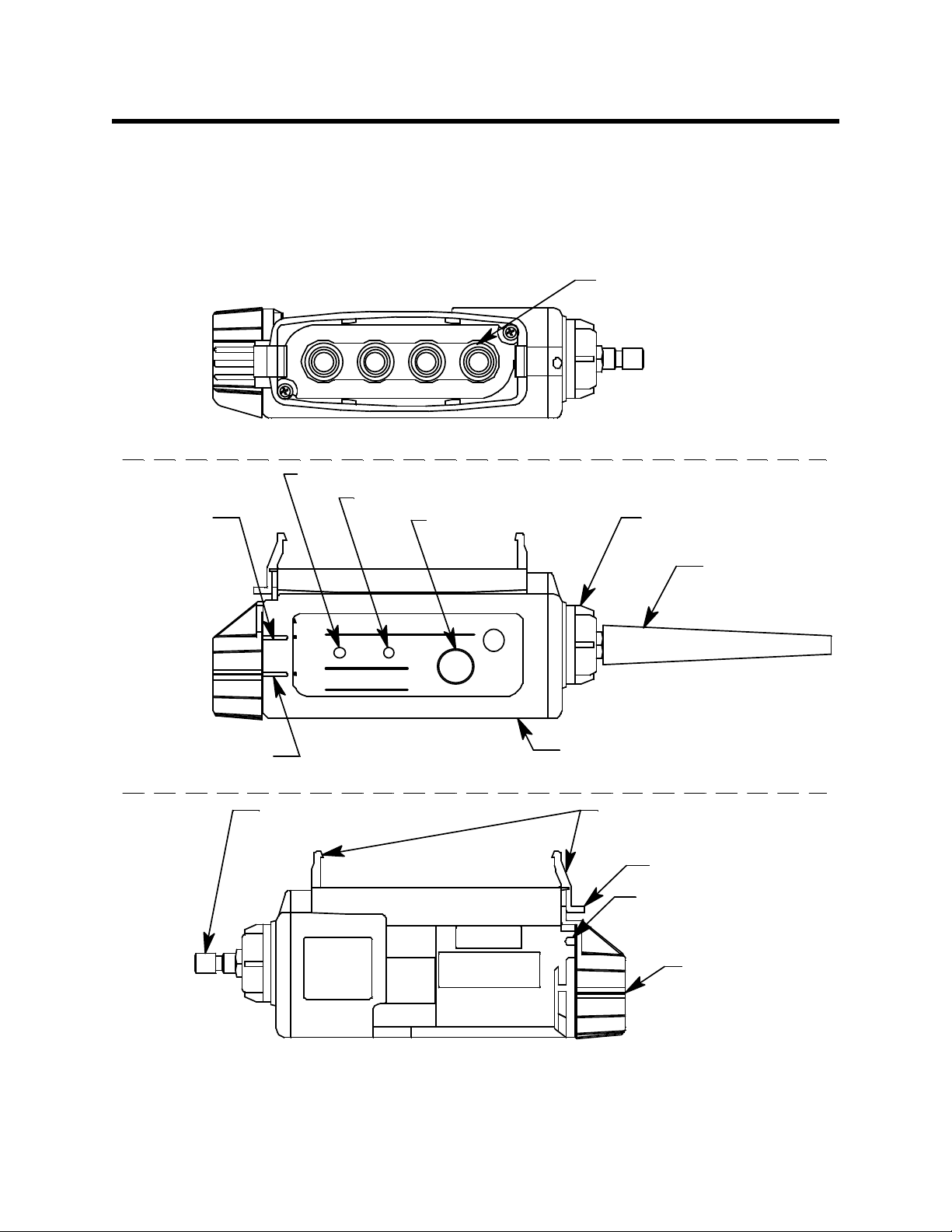
Description
Instrument
Release
Indicator
Power LED
Low Flow LED
Power Button
Top
Sensor Adapter
LOCK
POWER
LO W FLO W
RESET
POWER
RP-20 09
Pump Unit
Instrument Lock
Indicator
RELEASE
Front
Back
Inlet Fitting (GX-7 Type)
OPEN
Rubb er
Sample Nipple
Exhaust Fitting
Release Tab
Battery Cap
Instrument Retaining Clips
Filter Holder
The RP-2009 pump is a sample drawing accessory for the
GX-2009 Gas Monitor. It consists of the pump unit and the
rubber sample nipple.
Figure 1: RP-2009 Pump Component Location
RP-2009 Pump for the GX-2009 2
Page 6

Pump Unit
The pump unit is housed in a red plastic case. A GX-7 type male
quick connect fitting is located on one end of the pump unit.
This is the inlet fitting to the pump unit. The GX-7 quick connect
is installed in a removable clear plastic filter holder. A cotton
dust filter is inside the filter holder. The filter holder may be
removed by turning it counterclockwise and pulling it away
from the pump unit. Two flat membrane disk hydrophobic
filters and a wire mesh disk are located in the pump unit on the
filter holder end.
The battery compartment is located on the other end of the
pump unit. One AA alkaline battery is installed in the battery
compartment and held in place by a black plastic battery cap.
The battery cap may be removed for access to the battery by
pushing it down, turning it 1/4 turn counterclockwise, and
pulling it away from the pump unit.
The exhaust fitting is located under the battery cap tab.
A POWER button, a power indication LED, and a low flow LED
are located along the middle front of the pump unit. The power
LED is on when the pump unit is on. The low flow LED flashes
when the pump is experiencing a low flow condition.
An instrument release indicator and an instrument lock
indicator are located on the front left of the pump unit. The
indicator tab on the battery cap indicates the current position of
the battery cap.
Inside the pump unit case are the circuit board and diaphragm
pump. There are no user serviceable components inside the
pump unit case except for the battery accessible through the
battery cap and the wire mesh and hydrophobic disk filters
accessible through the filter holder.
The pump unit is configured to mate with the sensor face of the
GX-2009. Retaining tabs on the top of the RP-2009 snap onto the
sensor face of the GX-2009. The GX-2009 must be ins talled so the
front of the instrument is facing the front of the RP-2009. When
installed, the RP-2009 seals to the GX-2009’s sensor face with a
3 RP-2009 Pump for the GX-2009
Page 7

gasket.
Rubber Sample Nipple
A cone shaped 4 inch long rubber sample nipple is included
with the RP-2009 and is normally installed on the inlet fitting by
pushing the larger end over it. The smaller end can be inserted
in a hole or some other access to an enclosed area to sample the
environment.
Optional Hose & Probe
When desired, the rubber sample nipple may be removed and a
sample hose and probe with GX-7 fittings (optional accessories)
may be connected to the inlet fitting. Sample hose lengths are
available from 10 feet to 30 feet (see Parts List at the end of the
manual).
CAUTION: Sample hose lengths of more than 30 feet are not
recommended for the RP-2009 because of flow rate
reduction.
RP-2009 Pump for th e GX-2009 4
Page 8

Operation
"RELEASE"
Indicator Tab
S
L
O
C
E
P
U
S
H
E
P
O
N
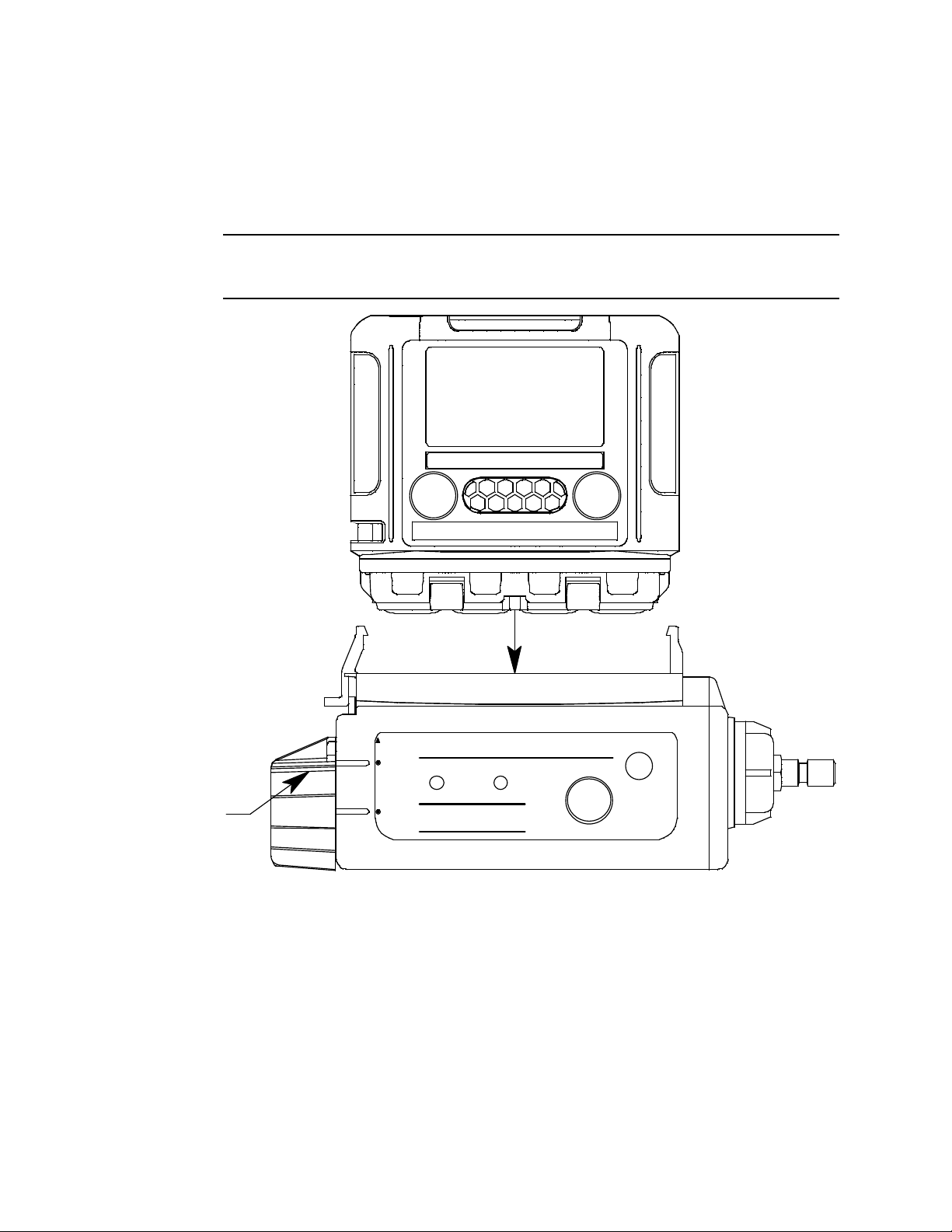
Normal Operation
1. Start up the GX-2009 and enter normal operation as
2. Push down on the RP-2009’s battery cap and rotate it 1/8
described in the GX-2009 Operator’s Manual.
turn counterclockwise so that the indicator tab on the battery
cap is next to “RELEASE”.
Figure 2: Releasing the Battery Cap
WARNING: Do not install the GX-2009 onto the RP-2009 without rotating the battery cap to
“RELEASE”. Installing the GX-2009 onto the RP-2009 with th e battery cap in
the “LOCK” position may result in damage to the RP-2009.
3. Be sure the front labels on the GX-2009 are facing the same
way as the front labels on the RP-2009. The retaining tabs on
the RP-2009 are keyed to allow installation of the GX-2009
only if the labels on both instruments are facing fr ont. Do not
force the GX-2009 into the RP-2009 if both labels are not
facing front.
4. Push the GX-2009 sensor face onto the RP-2009’s top face
5 RP-2009 Pump for the GX-2009
Page 9
until the GX-2009 is seated in the RP-2009 and the retaining
POWER
MODE
LOWFLOW
RESE T
AIR
OPEN
LOCK
RELEASE
POWER
Indicator Tab
POWER
H2S CO %LEL O2
RKI GX-2 009
RP-2009
clips are fully engaged with the GX-2009. Be sure that the RP2009 is fully engaged on the instrument. When fully engaged,
the GX-2009 should not move around at all.
CAUTION: If the RP-2009 is not fully engaged, the unit will not
respond to the target gases properly.
Figure 3: Connecting the RP-2009 to the GX-2009
RP-2009 Pump for th e GX-2009 6
Page 10

5. Secure the GX-2009 in the RP-2009 by pushing down on the
"LOCK"
PUSH
E
S
L
O
E
P
O
C
Indicator Tab
N
battery cap and rotating it an 1/8 turn clockwise so that the
indicator tab on the battery cap is next to “LOCK”.
Figure 4: Locking the Battery Cap
7 RP-2009 Pump for the GX-2009
Page 11
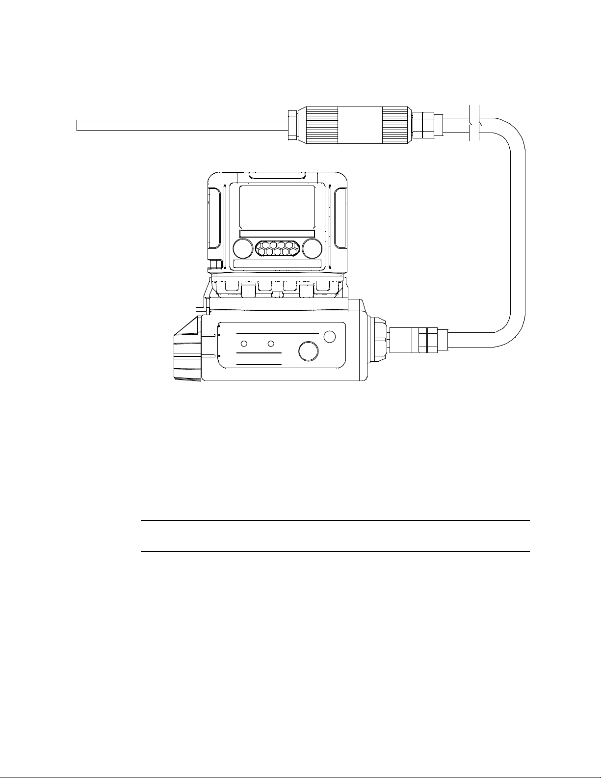
6. Attach the rubber sample nipple or an optional hose and
AIR
POWER
MODE
H2SCO%LELO
2
RKI GX-2009
POWER
RESET
LOW FLOWPOWER
LOCK
RELEASE
OPE N
RP-2009
probe to the inlet fitting.
Figure 5: Connecting the Optional Hose & Probe
7. Attach the RP-2009/GX-2009 assembly to your belt or
clothing using the belt clip on the GX-2009.
8. Turn on the pump unit by pressing and holding the POWER
button until the RP-2009 beeps and the power indication LED
turns green, about 2 seconds.
W ARNING: While the GX-2009 is installed in the RP-2009, the pump must be on for the
GX-2009 to function as a gas det ecti on monitor.
9. Go to the area to be sampled.
If the rubber sample nipple is used, detach the RP-2009/GX-
2009 assembly from your belt and hold the RP-2009/GX-2009
assembly near the area to by sampled. If sampling from a
vessel or an enclosed area is desired, insert the rubber sample
nipple into the vessel or enclosed area. Allow the pump unit
to sample for 90 seconds for a full response on the GX-2009.
RP-2009 Pump for th e GX-2009 8
Page 12

If an optional hose and probe are used instead of the rubber
sample nipple, hold the probe in the area to be sampled. To
sample from a well or other similar sample area, the hose and
probe may be lowered into the sample ar ea. Allow the pump
unit to sample for 90 seconds for a full response on the
GX-2009.
NOTE: Although the RP-2009 pump does have a hydrophobic
filter built in, the optional probe does not have a
hydrophobic filter. It has a dust filter only.
10.Monitor the GX-2009 display for the gas readings and take
appropriate action if gas alarms occur.
1 1.When sampling is complete, go to a fresh air area and turn of f
the pump unit.
12.Remove the RP-2009/GX-2009 assembly from your belt or
clothing.
13.Turn off the RP-2009 by pressing and holding the POWER
button until the RP-2009 sounds a long beep and the power
indicator LED turns off, about 3 seconds.
14.Turn off the GX-2009.
9 RP-2009 Pump for the GX-2009
Page 13

15.To remove the GX-2009 from the RP-2009, push down on the
"RELEASE"
Indicator Tab
S
L
O
C
E
P
U
S
H
E
P
O
N
battery cap and rotate it an 1/8 turn counterclockwise so that
the indicator tab on the battery cap is next to “RELEASE”.
Figure 6: Releasing the Battery Cap
W ARNING: Do not remove the GX-2009 from the RP-2009 without rotating the battery cap to
“RELEASE”. Removing the GX-2009 from the RP-2009 with the battery cap in
the “LOCK” position may result in damage to the RP-2009.
RP-2009 Pump for th e GX-2009 10
Page 14

16.Press the bottom of the release tab toward the pump unit and
LOWFLOW
POWER
RESET
Indicator Tab
LOCK
RELEASE
OPEN
AIR
POWER
MODE
H2S CO %LEL O
2
RP-2009
POWER
Release Tab
RKI GX-2009
pull up on the GX-2009.
Figure 7: GX-2009 Removal
Low Flow Alarm
When pump unit experiences a low flow condition, the low flow
LED starts flashing and the pump stops operating. Check the
rubber sample nipple and filters to make sure they are clear. If a
hose and probe are used, check them for kinks or obstructions.
To reset the low flow condition, press and release the POWER
button. If the low flow condition persists, the pump may need
servicing.
11 RP-2009 Pump for the GX-2009
Page 15

Maintenance
Replacing The Battery
1. Locate the black plastic battery cap on one end of the pump
unit.
2. Push down and rotate battery cap counterclockwise until it
stops, 1/4 of a turn.
3. Pull the battery cap away from the pump unit.
4. Remove the old battery from the pump unit. It will slide right
out.
5. Insert the new battery + end first into the pump unit. Use an
AA alkaline. The battery orientation is shown on the bottom
of the pump unit.
6. Slide the battery cap over the battery onto the pump unit,
push it down and turn it clockwise unit is stops beneath the
instrument release tab.
Replacing the Cotton Dust Filter
1. Locate the clear plastic filter holder at one end of the pump
unit.
2. Grasp the ridged sides of the filter holder and turn it 1/4 of a
turn counterclockwise.
3. Pull the filter holder away from the pump unit.
4. Remove the old cotton dust filter from the filter holder and
replace it with a new cotton dust filter.
5. Reinstall the filter holder. Align the two tabs on the bottom of
the filter holder with the two slots in the pump unit. Push the
filter holder into the pump unit and turn it 1/4 turn
clockwise until it snaps into place.
RP-2009 Pump for th e GX-2009 12
Page 16
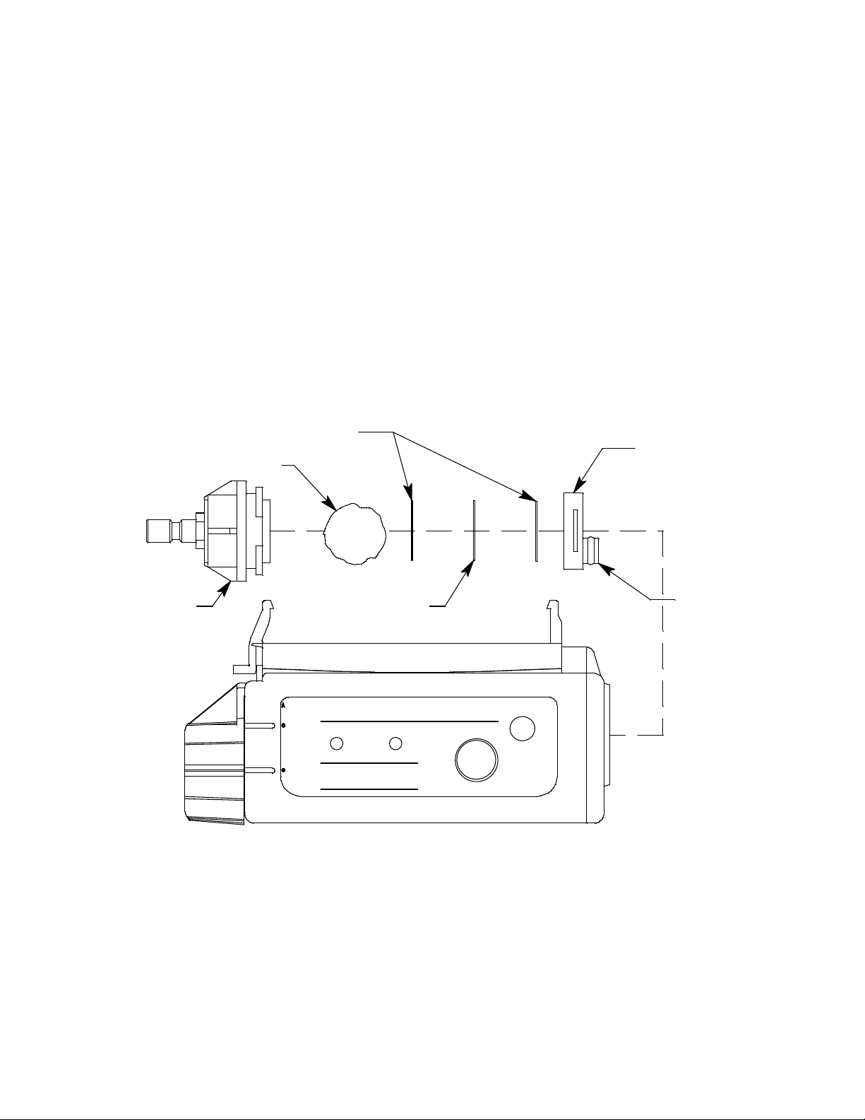
Replacing the Hydrophobic Disk Filter
POWER
RESET
Rubber Gasket
Installation
Stub
LOW FL OWPOW ER
LOCK
Cotton Dust Filter
Hydrophobic Disk Filter
OPEN
RP-2009
RELEASE
WireMeshDiskFilter Holder
and Wire Mesh Disk
1. Locate the clear plastic filter holder at one end of the pump
unit.
2. Grasp the ridged sides of the filter holder and turn it 1/4 of a
turn counterclockwise.
3. Pull the filter holder away from the pump unit. Do not lose
the cotton dust filter.
4. The hydrophobic disk filters and wire mesh disk are located
in the pump unit and are retained by a rubber gasket. Pull
out the rubber gasket with needle nose pliers.
13 RP-2009 Pump for the GX-2009
Figure 8: Changing the Hydrophobic & Wire Mesh Filters
5. Remove the old hydrophobic filters and/or wire mesh disk
from the gasket. A hy drophobic fi lter is located on e ither side
of the wire mesh disk.
6. Install the new hydrophobic filters and/or wire mesh disk
making sure a hydrophobic filter is located on each side of
Page 17

Parts List
the wire mesh disk.
7. Reinstall the gasket with the parts into the pump unit.
8. Reinstall the filter holder with the cotton dust filter. Align the
two tabs on the bottom of the filter holder with the two slots
in the pump unit. Push the filter holder into the pump unit
and turn it 1/4 turn clockwise until it snaps into place.
Table 2 lists replacement parts and accessories for the RP-2009
pump.
Table 2: Parts List
Part Number Description
07-2005RK Gasket, filter/screen retaining
07-6027RK O-ring, for battery compartment
17-1001RK Tapered rubber nozzle
21-1833RK Filter holder, clear plastic
21-1895RK Battery cap
33-0159RK Hydrophobic disk filter
33-1031RK Cotton ball 25 pack, for replacement of cotton
dust filter
33-1112RK Wire mesh disk filter
49-1120RK AA alkaline battery
80-0009RK-XX Sample hose (optional). Replace “XX” with
length in feet. Availab le le ng ths fo r the R P- 20 09
are 10, 15, 20, 25, & 30 feet.
80-0150RK Sample probe with dust filter (optional)
RP-2009 Pump for th e GX-2009 14
 Loading...