

Page 1

PT1E-1050
Indicator/Alarm Unit
RM-5000 Series
Operating Manual
Request for the Customers
• Read and understand this operating manual before using the indicator/alarm unit.
• Use the indicator/alarm unit in accordance with the operating manual.
• Regardless of warranty period, we shall not make any indemnification for accidents and
damage caused by using this product.
Make sure to read the warranty policy specified on the warranty.
• Because this is a safety unit, a regular maintenance for every six months and daily
maintenance must be performed.
• If any abnormality is found in the indicator/alarm unit, notify it to RIKEN KEIKI immediately.
(Visit our Web site to find your nearest RIKEN KEIKI office.)
Page 2

<Contents>
1 Outline of the Product.............................................................................................. 3
1-1. Preface .................................................................................................................... 3
1-2. Purpose of use ........................................................................................................3
1-3. Definition of DANGER, WARNING, CAUTION, and NOTE ..................................... 4
2 Important Notices on Safety .................................................................................... 5
2-1. Danger cases ..........................................................................................................5
2-2. Warning cases......................................................................................................... 6
2-3. Precautions ............................................................................................................. 7
3 Product Components............................................................................................... 8
3-1. Main unit and accessories ....................................................................................... 8
3-2. Outline drawing ....................................................................................................... 9
3-3. Names and functions for each part.......................................................................... 10
3-3. Block diagram.......................................................................................................... 14
4 How to Use.............................................................................................................. 15
4-1. Before using the indicator/alarm unit ....................................................................... 15
4-2. Precautions for installation points............................................................................ 15
4-3. Precautions for system designing............................................................................ 16
4-4. How to install ........................................................................................................... 19
4-5. How to wire.............................................................................................................. 21
5 How to Operate ....................................................................................................... 31
5-1. Preparation for start-up............................................................................................ 31
5-2. Basic operating procedures..................................................................................... 32
5-3. How to start the indicator/alarm unit ........................................................................ 33
5-4. Modes...................................................................................................................... 34
5-5. Detection mode ....................................................................................................... 36
5-6. Alarm test mode ...................................................................................................... 37
5-7. User mode............................................................................................................... 38
5-8. How to exit...............................................................................................................42
6 Operations and Functions ....................................................................................... 43
6-1. Gas alarm activation................................................................................................ 43
6-2. Fault alarm activation .............................................................................................. 47
6-3. External output operation ........................................................................................ 48
6-4. Other functions ........................................................................................................ 50
7 Maintenance............................................................................................................ 52
7-1. Maintenance intervals and items ............................................................................. 52
7-2. Regular maintenance mode .................................................................................... 54
7-3. Gas calibration method............................................................................................ 69
7-4. How to clean............................................................................................................ 72
7-5. How to replace the fuse........................................................................................... 72
8 Storage, Relocation and Disposal ........................................................................... 73
8-1. Procedures to store the indicator/alarm unit or leave it for a long time.................... 73
8-2. Procedures to relocate the indicator/alarm unit or use it again................................ 73
8-3. Disposal of products................................................................................................ 73
9 Troubleshooting....................................................................................................... 74
10 Product Specifications ............................................................................................. 77
10-1. List of specifications ................................................................................................ 77
10-2. Product components................................................................................................ 79
11 Definition of Terms................................................................................................... 80
RM-5000 - 2 -
Page 3

1 Outline of the Product 1-1. Preface
1
Outline of the Product
1-1. Preface
Thank you for choosing our indicator/alarm unit RM-5000 series for use with the gas detection and alarm
system. Please check that the model number of the product you purchased is included in the specifications
on this manual.
This manual explains how to use the indicator/alarm unit and its specifications. It contains information
required for using the indicator/alarm unit properly. Not only the first-time users but also the users who have
already used the product must read and understand the operating manual to enhance the knowledge and
experience before using the indicator/alarm unit.
1-2. Purpose of use
• Use the indicator/alarm unit RM-5000 series in combination with a gas detector head on a one-on-one
basis.
GP-5001: Combustible gas indicator/alarm unit to be used in combination with a catalytic combustion
type detector head
NC-5001: Combustible gas indicator/alarm unit to be used in combination with a new ceramic type
detector head
NC-5001W: Combustible gas indicator/alarm unit with double range specifications to be used in
combination with a new ceramic type detector head
NP-5001: Combustible gas indicator/alarm unit to be used in combination with a thermal conductivity
type detector head
SP-5001: Combustible gas or toxic gas indicator/alarm unit to be used in combination with a hot-wire
semiconductor type detector head
GH-5001: Combustible gas or toxic gas indicator/alarm unit to be used in combination with a
semiconductor type detector head
EC-5002: Toxic gas indicator/alarm unit to be used in combination with an electrochemical type
detector head
OX-5001: Oxygen indicator/alarm unit to be used in combination with a detector head that uses an
oxygen sensor
OX-5002: Oxygen indicator/alarm unit to be used in combination with a detector head that uses an
oxygen sensor
RM-5002: Indicator/alarm unit to be used in combination with a gas detector head that outputs general
measurement signals
RM-5003: Gas indicator/alarm unit to be used in combination with a gas detector head with 3-wire
type 4 - 20 mA output specifications
- 3 - RM-5000
Page 4
1 Outline of the Product 1-3. Definition of DANGER, WARNING, CAUTION, and NOTE
• The gas detection and alarm system is a safety unit, not an analyzer or densitometer which performs
quantitative/qualitative analysis/measurement for gases. You must understand the features of the
indicator/alarm unit before using it, so that you can use it properly.
• The indicator/alarm unit displays a gas concentration on the character LCD (digital and bar meter display
<three colors of green, yellow, and red>) according to a signal from the detector head. Gas
concentrations are displayed in different colors according to danger levels, i.e., in green if neither of the
alarm setpoints is exceeded, in orange if the first alarm setpoint is exceeded, and in red if the second
alarm setpoint is exceeded.
• The indicator/alarm unit has two-step gas alarm contact and fault alarm contact.
• The indicator/alarm unit outputs gas concentration in 4 - 20 mA or digital data (RS-485: option).
1-3. Definition of DANGER, WARNING, CAUTION, and
NOTE
DANGER
WARNING
CAUTION
NOTE
This message indicates that improper handling may cause serious damage on
life, health or assets.
This message indicates that improper handling may cause serious damage on
health or assets.
This message indicates that improper handling may cause minor damage on
health or assets.
This message indicates advice on handling.
RM-5000 - 4 -
Page 5

2 Important Notices on Safety 2-1. Danger cases
2
Important Notices on
Safety
2-1. Danger cases
DANGER
This is not an explosion-proof unit.
- 5 - RM-5000
Page 6

2 Important Notices on Safety 2-2. Warning cases
2-2. Warning cases
WARNING
Specified devices
Connect the indicator/alarm unit only to the specified devices. If it is connected to any unspecified
device, the indicator/alarm unit or the connected device may be damaged.
Power supply
Before turning on the indicator/alarm unit, always check that the voltage is properly applied. Do not
use an unstable power supply because it may cause malfunctions.
Need of grounding circuit
Do not cut the grounding circuit or disconnect the wire from the grounding terminal.
Defects in protective functions
Before starting the indicator/alarm unit, check the protective functions for defects. When seeming
defects are found in the protective functions, such as protective grounding, do not start the
indicator/alarm unit.
External connection
Before connecting the indicator/alarm unit to the external device, securely connect it to a protective
grounding circuit.
Operation in a gas
Do not operate the indicator/alarm unit in a place where combustible gases or vapors are present.
Operating the indicator/alarm unit in such an environment will lead to extreme dangers.
Response to gas alarm
Issuance of a gas alarm indicates that there are extreme dangers. Take proper actions based on
your judgment.
RM-5000 - 6 -
Page 7

2 Important Notices on Safety 2-3. Precautions
2-3. Precautions
CAUTION
Do not use a transceiver near the indicator/alarm unit.
Radio wave from a transceiver, etc. near the indicator/alarm unit or its cables may disturb indication
reading. If a transceiver or other radio wave transmitting device is used, it must be used in a place
where it disturbs nothing.
To restart the indicator/alarm unit, wait for five seconds or more before doing it.
Restarting the indicator/alarm unit in less than five seconds may cause errors.
Do not use the external output of the indicator/alarm unit to control other units.
This is not a control unit. It is not allowed to use the external output of the indicator/alarm unit to
control other units.
Do not disassemble/modify the indicator/alarm unit, or change the settings if not necessary.
Disassembling/modifying the indicator/alarm unit will invalidate the warranty of the performance.
Changing the settings without understanding the specifications may cause alarm malfunctions.
Please use the indicator/alarm unit properly in accordance with the operating manual.
Never fail to perform a regular maintenance.
Since this is a safety unit, a regular maintenance on it and the detector head must be performed to
ensure safety.
- 7 - RM-5000
Page 8
3 Product Components 3-1. Main unit and accessories
3
Product Components
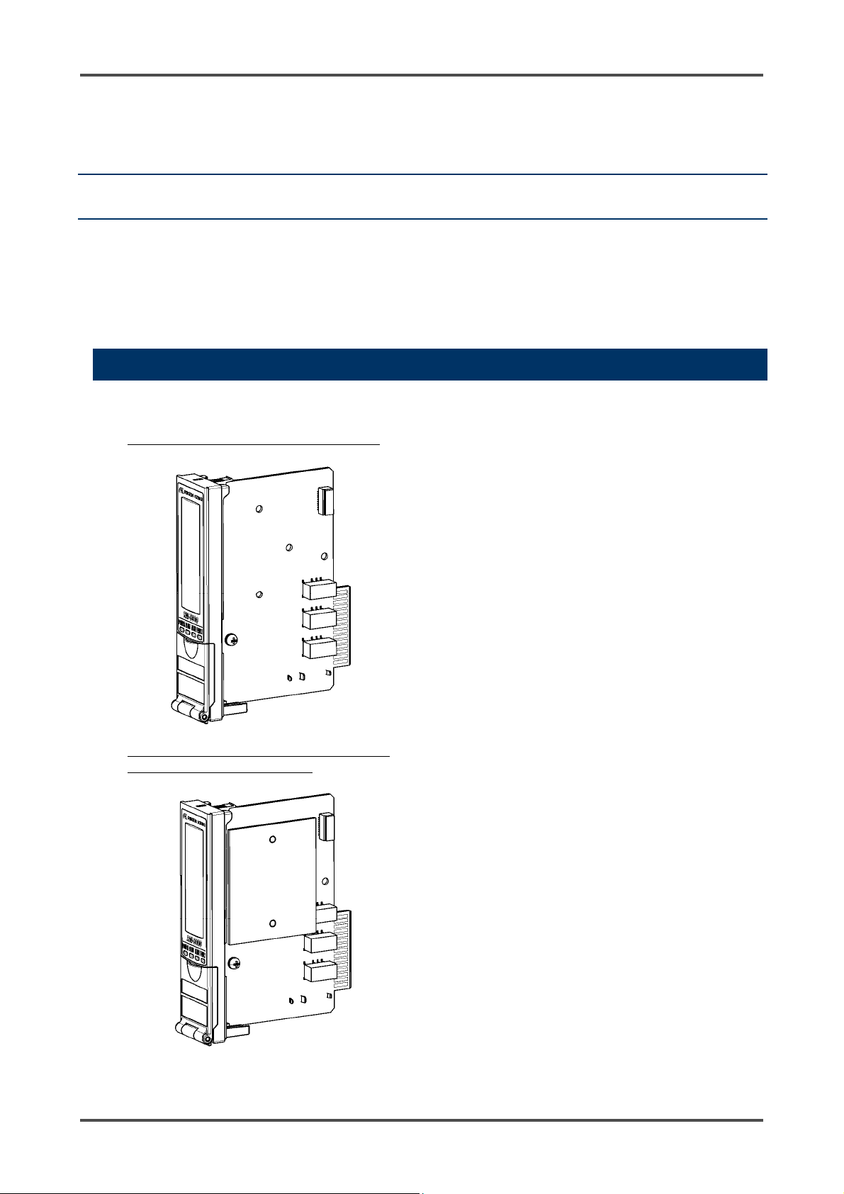
3-1. Main unit and accessories
<Main Unit (RM-5000 Series)> <Accessories>
EC-5002, OX-5002, RM-5002, RM-5003
• Operating manual
One copy per system regardless of the number of
units to be delivered
GP-5001, NC-5001, NC-5001W, NP-5001
SP-5001, GH-5001, OX-5001
RM-5000 - 8 -
Page 9
3 Product Components 3-2. Outline drawing
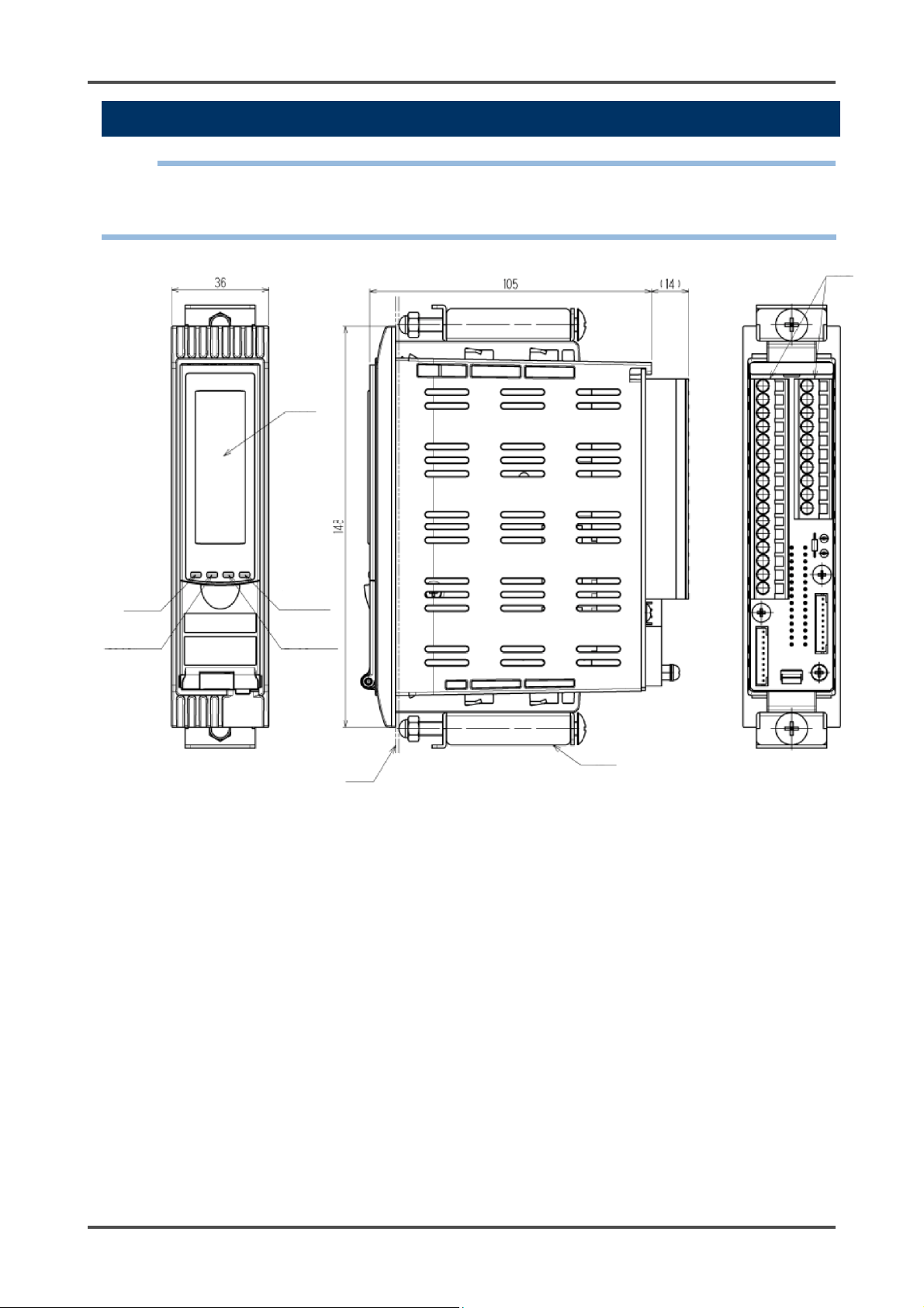
3-2. Outline drawing
NOTE
Install the indicator/alarm unit in a single-unit case (option) or multi-unit case (option) before using it.
This section explains the unit in a single-unit case.
For information on using a multi-unit case, see the operating manual of the multi-unit case.
Display
Terminal plate
Power lamp
First alarm lamp
Fault lamp
Second alarm
lamp
Panel
Fixing bracket
- 9 - RM-5000
Page 10
3 Product Components 3-3. Names and functions for each part
3-3. Names and functions for each part
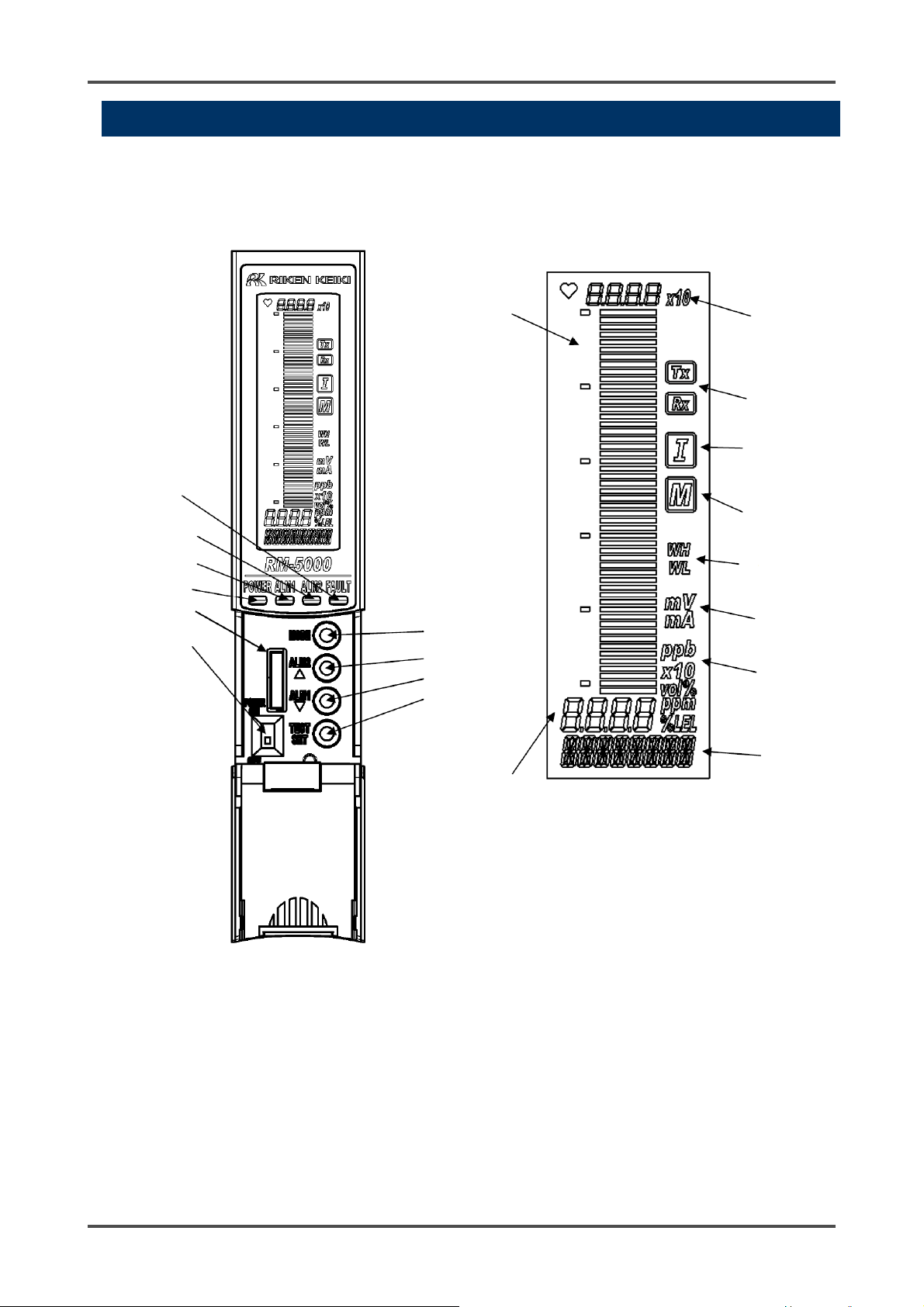
<Front Panel and Character LCD>
(9) Fault lamp
(8) Second alarm
lamp
(7) First alarm lamp
(6) Power lamp
(19) Maintenance
port
(1) Power switch
(11) Gas concentration
bar meter display
(2) MODE key
(3) ALM2/▲ key
(4) ALM1/▼ key
(5) TEST/SET key
(10) Gas concentration
digital value display
(13) Full scale value
display
(17) Digital
communication
display
(16) Inhibit display
(15) Maintenance
display
(18) Double range
display
(20) Current/voltage
display
(14) Unit display
(12) Gas name and
message
display
RM-5000 - 10 -
Page 11

3 Product Components 3-3. Names and functions for each part
Number in
Item Function
the figure
(1) POWER switch Power switch.
(2) MODE key Used to enter the maintenance mode.
It is also used to cancel or skip in a specific mode.
(3) ALM2/▲ key Used to switch screen or change a value (UP).
Also used to display the second alarm (ALM2) setpoint.
(4) ALM1/▼ key Used to switch screen or change a value (DOWN).
Also used to display the first alarm (ALM1) setpoint.
(5) TEST/SET key Used to enter the test mode.
It is used for value confirmation and so on in a specific mode.
(6) Power lamp (POWER) Power lamp. It lights up in green when the power is on.
(7) First alarm lamp
(ALM1)
(8) Second alarm lamp
(ALM2)
First alarm lamp. It blinks or lights up in red when the first alarm is
reached.
Second alarm lamp. It blinks or lights up in red when the second
alarm is reached.
(9) Fault lamp (FAULT) Fault lamp. It lights up in yellow when an abnormality is detected
in the indicator/alarm unit.
(10) Gas concentration
Displays the gas concentration and so on.
digital value display
(11) Gas concentration bar
meter display
The detectable range (full scale = FS) is divided into 50 with bars.
The increase in concentration is displayed in proportion to the full
scale.
(12) Gas name display Displays gas name in chemical formula, etc. (e.g. CH4 for
methane)
(13) Full scale value display Displays the full scale value of a detected gas.
(14) Gas concentration unit
display
Displays the unit according to the specification (ppm, ppb,
vol%, %, %LEL).
(15) Maintenance display Displayed during the maintenance mode. When this indicator is
displayed, the alarm contact is disabled.
(16) Inhibit display Displayed when the inhibition (point skip) is set.
(17) Digital communication
display (*1)
(18) Double range display
(*2)
For RS-485 communications, this indicator is displayed (TX, RX)
while transmitting data with the upper unit.
Displayed for the double range specifications (WH: High range,
WL: Low range).
(19) Maintenance port Used by a service engineer during maintenance. This is not
typically used by the user.
(20) Current/voltage display Displayed during the environmental setting (adjustment and
setting operations) for the sensor in maintenance mode.
*1: Displayed only on a model with RS-485 (option) mounted.
*2: Displayed only on NC-5001W.
- 11 - RM-5000
Page 12
3 Product Components 3-3. Names and functions for each part
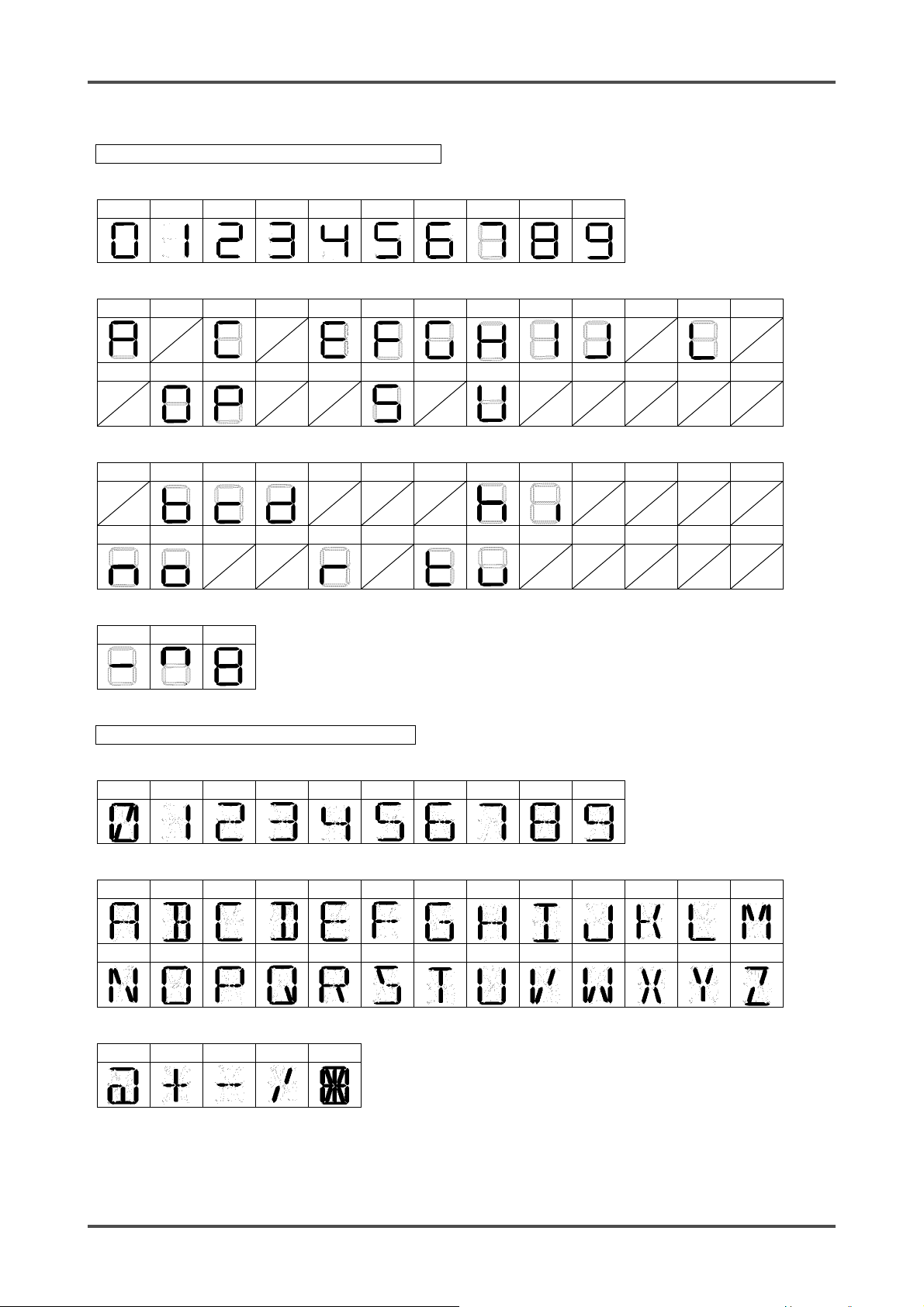
<List of Display Symbols>
Gas concentration digital display (seven-segment)
Numbers
0 1 2 3 4 5 6 7 8 9
Alphabet (upper-case)
A B C D E F G H I J K L M
N O P Q R S T U V W X Y Z
Alphabet (lower-case)
a b c d e f g h i j k l m
n o p q r s t u v w x y z
Symbols
- ^
~
Gas name and message display (14-segment)
Numbers
0 1 2 3 4 5 6 7 8 9
Alphabet (upper-case)
A B C D E F G H I J K L M
N O P Q R S T U V W X Y Z
Symbols
@ + - /
~
RM-5000 - 12 -
Page 13
3 Product Components 3-3. Names and functions for each part
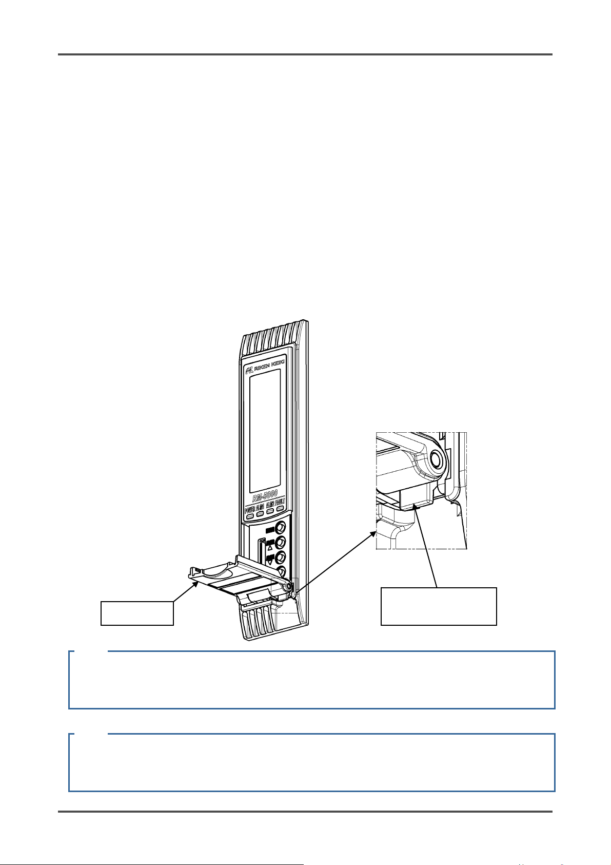
<Attaching or Detaching Battery Unit>
Attach or detach the indicator/alarm unit from the single-unit case or multi-unit case according to the
following procedure.
(1) Attaching procedure
• Open the front cover of the indicator/alarm unit.
• Make sure that the power switch of the indicator/alarm unit is OFF.
• Insert the indicator/alarm unit along the rail into the single-unit case or multi-unit case.
• Push it in until an click is heard and you feel that it is locked in.
• Gently pull it to make sure that the indicator/alarm unit does not come off.
• Close the front cover of the indicator/alarm unit.
(2) Detaching procedure
• Open the front cover of the indicator/alarm unit.
• Make sure that the power switch of the indicator/alarm unit is OFF.
• While pressing the lock lever on the lower right of the indicator/alarm unit, hold the front cover and
pull it out of the case.
• Close the front cover of the indicator/alarm unit.
CAUTION
CAUTION
Front cover
Turn off the power of the indicator/alarm unit before attaching or detaching it. Otherwise, a failure
may be caused.
This is a precision device. Be careful not to drop it when detaching it. Dropping the unit
compromises its original performance or causes malfunctions.
the lock lever upward.
Press
- 13 - RM-5000
Page 14
3 Product Components 3-3. Block diagram
(
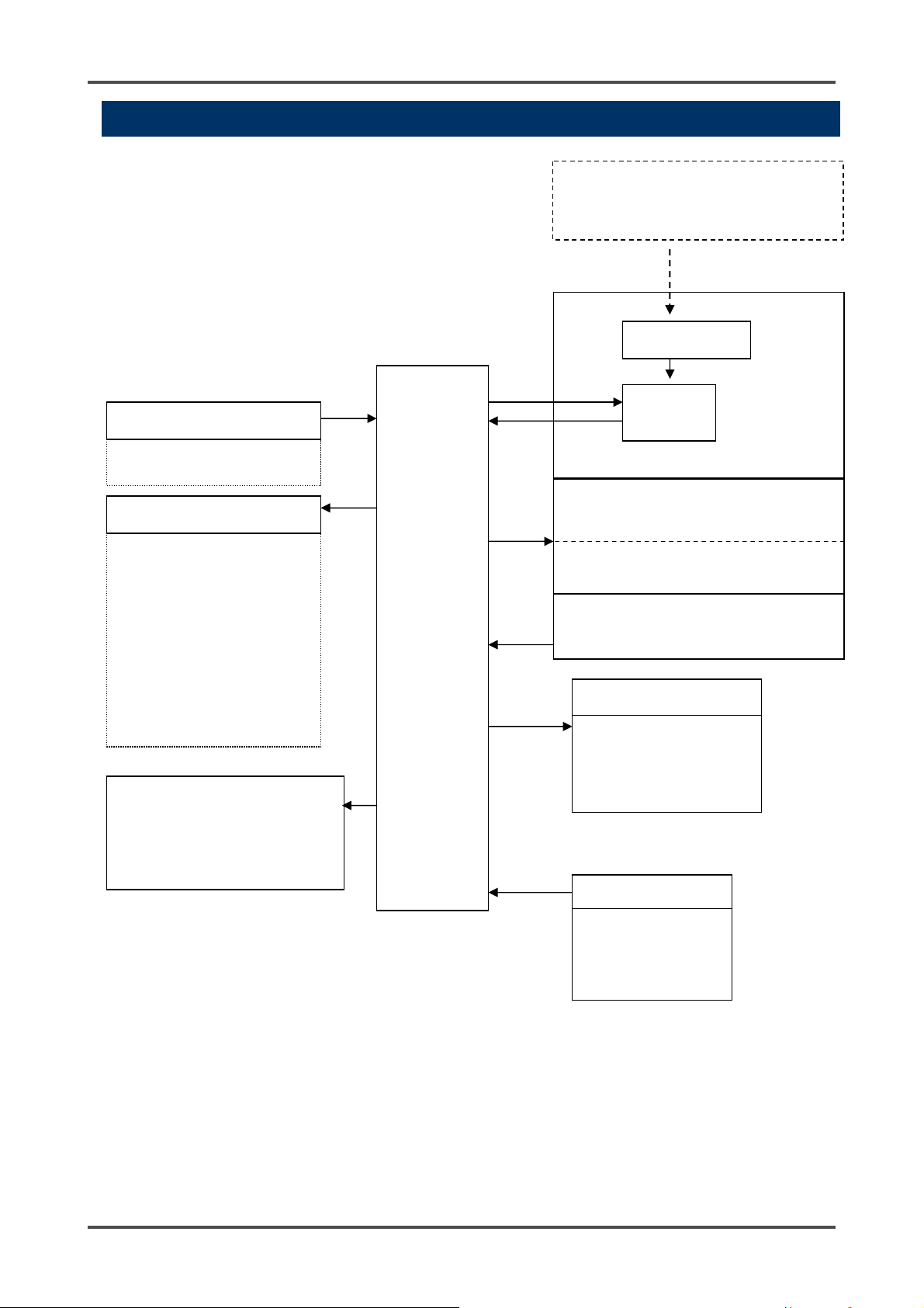
3-3. Block diagram
*1: Installed only in GP-5001, NC-5001, NC-5001W, NP-5001, SP-5001, GH-5001, OX-5001.
*2: Only on a model with RS-485 (option) mounted.
Power supply part
POWER INPUT (24 VDC)
Alarm contact controller
Gas alarm contact (ALM1,
ALM2)
Fault alarm contact (FAULT)
* Standard setting of
contact activation
• De-energized
(De-energized at a
normal state)
• ON-ALARM
(Closed contact at an
alarm state)
Transmitter
4-20 mA DC transmission
Digital data (RS-485)
transmission (*2)
Controller
(CPU)
Bar meter, gas name display,
concentration display, unit display, etc.
Detector head (option)
Amplifier (*1)
Controller
(CPU)
(POWER) (ALM1) (ALM2) (FAULT)
Operating unit
(MODE) (ALM2/▲) (ALM1/▼)
Alarm signal controller
Gas alarm signal
(ALM1, ALM2) output
Fault alarm signal
(FAULT) output
Control signal input
Reset signal input
Test input
Buzzer stop
signal input
LCD display
Lamp
TEST/SET)
RM-5000 - 14 -
Page 15

4 How to Use 4-1. Before using the indicator/alarm unit
4
How to Use
4-1. Before using the indicator/alarm unit
Not only the first-time users but also the users who have already used the product must follow the operating
precautions.
Ignoring the precautions may damage the indicator/alarm unit, resulting in inaccurate gas detection.
NOTE
Install the indicator/alarm unit in a single-unit case (option) or multi-unit case (option) before using it.
This section explains using the single-unit case.
For information on using the multi-unit case, see the operating manual of the multi-unit case.
4-2. Precautions for installation points
CAUTION
This is a precision device. Because the indicator/alarm unit may not provide the specified
performance in some places (environments), check the environment in the installation point, and
then take appropriate actions if necessary.
Because the indicator/alarm unit plays an important role for safety and disaster prevention, you
must install as many units of the indicator/alarm unit as needed in appropriate points.
Because points where gases leak and remain easily are different depending on the types of gases
and the working areas, please decide carefully installation sites and the number of units to be
installed.
Do not install the indicator/alarm unit in a place with vibrations or shocks.
The indicator/alarm unit consists of sensitive electronic parts. The indicator/alarm unit must be installed in a
stable place without vibrations or shocks and it cannot drop.
Do not install the indicator/alarm unit in a place exposed to water, oil or chemicals.
When selecting installation points, avoid a place where the indicator/alarm unit is exposed to water, oil or
chemicals.
Do not install the indicator/alarm unit in a place where the temperature drops below -10ºC or rises over
40ºC.
The operating temperature of the indicator/alarm unit is -10 to 40ºC. The indicator/alarm unit must be
installed in a stable place where the operating temperature is maintained and does not change suddenly.
- 15 - RM-5000
Page 16
4 How to Use 4-3. Precautions for system designing
Do not install the indicator/alarm unit in a place exposed to direct sunlight or sudden changes in the
temperature.
When you select installation sites, avoid a place where it is exposed to direct sunlight or radiant heat
(infrared rays emitted from a high-temperature object), and where the temperature changes suddenly.
Condensation may be formed inside the indicator/alarm unit, or the indicator/alarm unit cannot adjust to
sudden changes in the temperature.
Keep the indicator/alarm unit (and its cables) away from noise source devices.
When selecting installation points, avoid a place where high-frequency/high-voltage devices exist.
Do not install the indicator/alarm unit in a place where maintenance of the indicator/alarm unit cannot be
performed or where handling the indicator/alarm unit involves dangers.
Regular maintenance of the indicator/alarm unit must be performed.
Do not install the indicator/alarm unit in a place where the machinery must be stopped when maintenance is
performed in its inside, where parts of the machinery must be removed to perform maintenance, or where
the indicator/alarm unit cannot be removed because tubes or racks prevent access to it. Do not install the
indicator/alarm unit in a place where maintenance involves dangers, for example, near a high-voltage cable.
Do not install the indicator/alarm unit in machinery which is not properly grounded.
Before installing the indicator/alarm unit in machinery, the machinery must be grounded properly.
Do not install the indicator/alarm unit in a place where other gases exist around it.
The indicator/alarm unit must not be installed in a place where other gases exist around it.
4-3. Precautions for system designing
CAUTION
An unstable power supply and noise may cause malfunctions or false alarms.
The descriptions in this section must be reflected on the designing of a system using the
indicator/alarm unit.
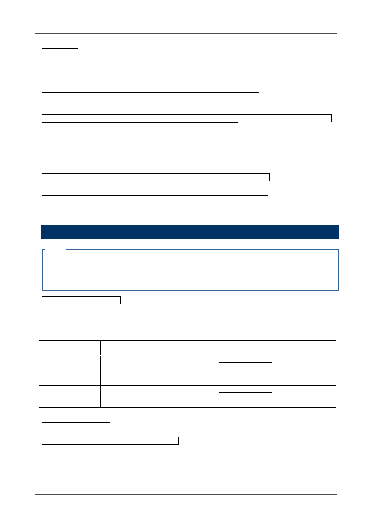
Using a stable power supply
The external output and alarm contact of the indicator/alarm unit may be activated when the power is turned
on, when momentary blackout occurs, or when the system is being stabilized. In such cases, use a safety
power supply, or take appropriate actions on the receiving side.
The indicator/alarm unit must be provided with the following power supply.
Power supply
voltage
Allowed time of
momentary
blackout
Others
Heat radiation designing
When it is installed in the closed instrumentation panel, attach ventilation fans above and below the panel.
Introducing protective measures against lightning
If cables are installed outside the factory/plant, or if internal cables are installed in the same duct as the
cables coming from outside the factory/plant, "lightning" will cause problems. Because lightning acts as a
large emission source while cables act as a receiving antenna, devices connected to the cables may be
damaged.
24 VDC (21.6 – 26.4 VDC) (Terminal voltage of the indicator/alarm unit)
Up to 10 milliseconds
(To recover from the momentary
blackout for 10 milliseconds or more,
restart the indicator/alarm unit.)
Do not use it with a power supply of
large power load or high-frequency
noise.
Example of actions
To ensure continuous operation and
activation, install a protective power
supply outside the indicator/alarm unit.
Example of actions
Use a line filter to avoid the noise source
if necessary.
RM-5000 - 16 -
Page 17

4 How to Use 4-3. Precautions for system designing
Lightning cannot be prevented. Cables installed in a metal conduit or under the ground cannot be
completely protected from inductive lightning surge caused by lightning. Although complete elimination of
disasters caused by lightning is impossible, the following protective measures can be taken.
Take appropriate measures in accordance with the importance of the facilities and the
environment.
• Connect the transmission signal route by using optical fiber.
Protection
against lightning
Grounding
* The lightning arrester has a circuit to remove a surge voltage which damages field devices, so that
signals may be attenuated by installing the arrester. Before installing a lightning arrester, verify that it
works properly.
Proper use of alarm contact
The alarm contact of the indicator/alarm unit is used to transmit signals to activate an external buzzer or
alarm lamp. Do not use the indicator/alarm unit for controlling purpose (e.g., controlling the shutdown valve).
CAUTION
The "b" contact (break contact) under de-energized state may be opened momentarily by a physical
shock, such as external force.
When the "b" contact is selected for the alarm contact, take appropriate actions to prepare for a
momentary activation, for example, add signal delay operation (approximately one second) to the
receiving side of the "b" contact.
The specifications for the alarm contact of the indicator/alarm unit are based on the resistant load conditions.
If inductive load is used at the alarm contact, the following errors will occur easily because counter
electromotive force is generated at the contact.
• Deposition, defective insulation or defective contact at the relay contact
• Damage of any electric parts due to high-voltage generated inside the indicator/alarm unit
• Abnormal operations by an out-of-control CPU
CAUTION
• In principle, do not activate inductive load at the alarm contact of the indicator/alarm unit. (In
particular, never use the inductive load to activate a fluorescent lamp or motor.)
• If inductive load is activated, relay it with an external relay (contact amplification). However,
because the coil of an external relay also involves inductive load, select a relay at a lower
voltage (100 VAC or below), and then protect the contact of the indicator/alarm unit with an
appropriate surge absorbing part, such as a CR circuit.
• Provide protection by a lightning arrester (cable arrester).
(Although inductive lightning surge can be transmitted through the cable, it is
prevented by installing a lightning arrester before the field devices and central
processing equipment. For information on how to use a lightning arrester, please
contact the manufacturer.)
In addition to lightning, there are more sources of surge noise. To protect units from
these noise sources, the units must be grounded.
- 17 - RM-5000
Page 18
4 How to Use 4-3. Precautions for system designing
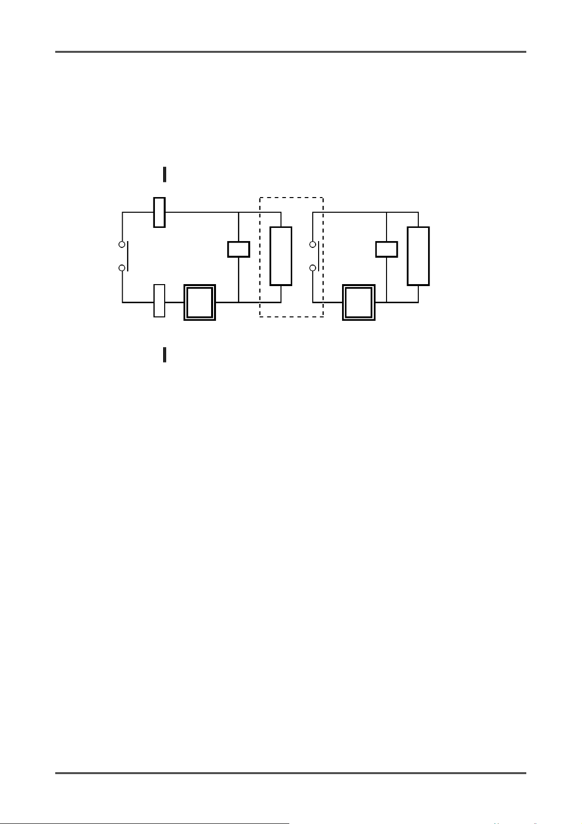
A
If load is to be activated, appropriate measures must be taken to stabilize the operation of the
indicator/alarm unit and protect the alarm contact referring to the following information.
• Relay it with an external relay at a lower voltage of 100 VAC or below (contact amplification). At the same
time, the surge absorbing part SK1 suitable for the specifications must be attached to the external relay.
• In addition, the surge absorbing part SK2 must be attached to the loaded side of the external relay if
necessary.
• It may be recommended that the surge absorbing part should be attached to the contact for certain load
conditions. It must be attached to an appropriate position by checking how the load is activated.
RM-5000
SK1 SK2
Coil
Load
larm contact
Power
supply
External relay
(low voltage relay)
* SK1, SK2: Surge absorbing parts
Power
supply
RM-5000 - 18 -
Page 19
4 How to Use 4-4. How to install
4-4. How to install
NOTE
Install the indicator/alarm unit in a single-unit case (option) or multi-unit case (option) before using it.
This section explains using the single-unit case.
For information on using the multi-unit case, see the operating manual of the multi-unit case.
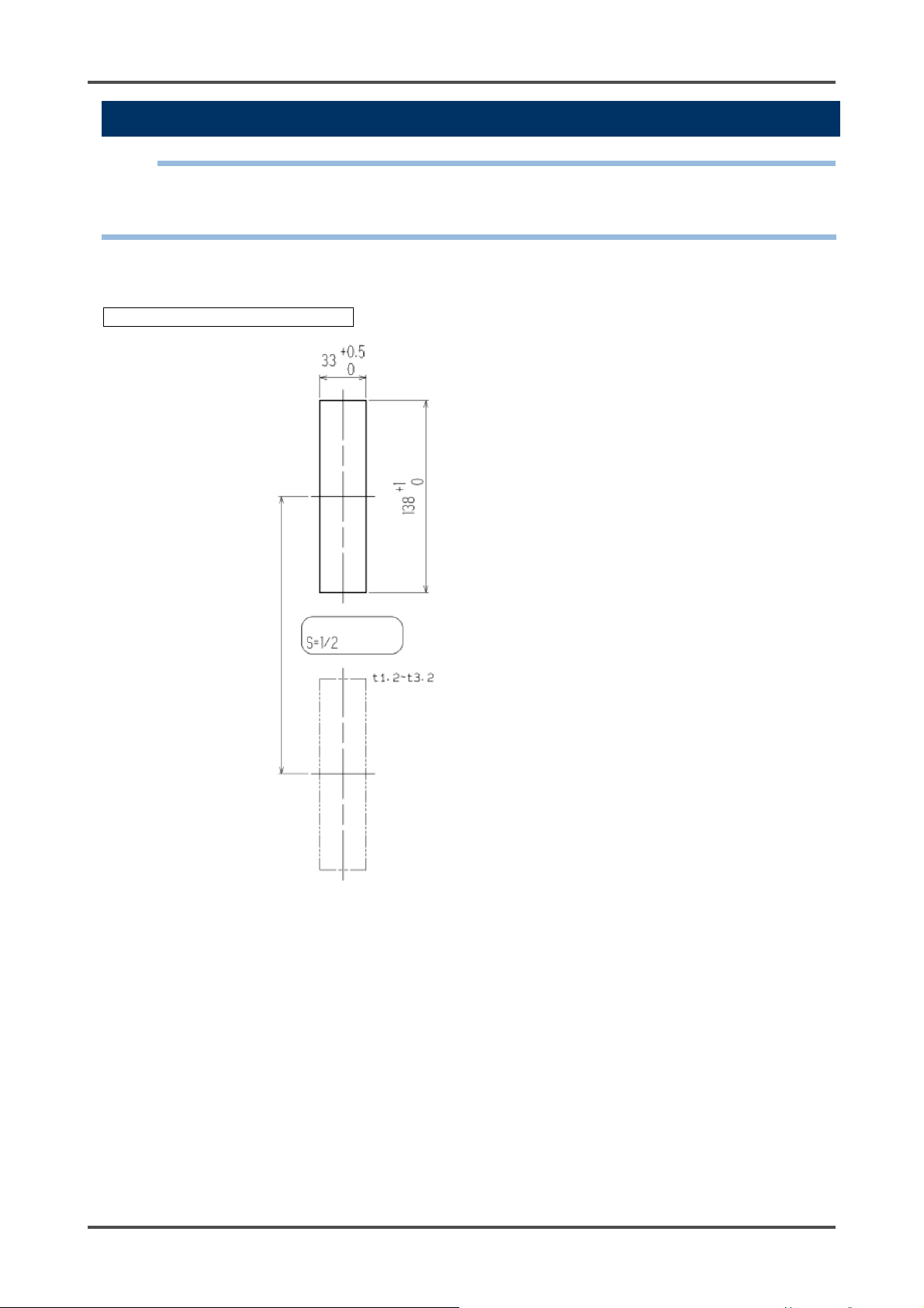
<Panel Cutout Dimensions>
When installed in two rows vertically
Single-point panel cutout
dimensions
200 or more
Panel thickness
- 19 - RM-5000
Page 20
4 How to Use 4-4. How to install
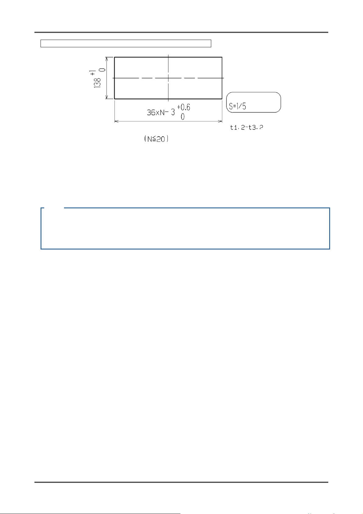
When installed in one row vertically and N columns horizontally
Multi-point panel cutout
dimensions
Panel thickness
N: Buzzer unit + Indicator/alarm unit
<Attaching procedure>
After drilling holes in the panel to install a single-unit case, attach the indicator/alarm unit according to the
following procedure.
(1) Insert the single-unit case from the rear terminal plate side to the panel front side.
(2) Set fixing bracket on the upper and lower parts of the single-unit case.
(3) Tighten the screws of the fixing bracket.
CAUTION
• Tightening the screws to a high torque may deform the case or damage the fixing bracket.
• Turn off the power of the indicator/alarm unit before attaching or detaching it. Otherwise, a failure
may be caused.
RM-5000 - 20 -
Page 21

4 How to Use 4-5. How to wire
4-5. How to wire
CAUTION
• Use the specified cables for each of the connections between the indicator/alarm unit and the
<Recommended Cables>
detector head.
• When wiring, be careful not to apply stresses on the terminal plate when (overweight) cables are
installed.
• The power cables and signal cables must not be installed together with the motor power cables,
etc.
• When stranded wires are used, prevent wires from contacting each other.
• Use the specified tools to wire.
Model Cable specifications
GP-5001
NC-5001
NC-5001W
SP-5001
NP-5001 Power supply: Equivalent to CVV (1.25 sq or 2.0 sq) - 2-core
OX-5001
OX-5002
RM-5002
GH-5001 Power supply: Equivalent to CVV (1.25 sq or 2.0 sq) - 2-core
EC-5002 Power supply: Equivalent to CVV (1.25 sq or 2.0 sq) - 2-core
RM-5003 Power supply: Equivalent to CVV (1.25 sq or 2.0 sq) - 2-core
Power supply: Equivalent to CVV (1.25 sq or 2.0 sq) - 2-core
Detector head: Equivalent to CVV (1.25 sq or 2.0 sq) - 4-core or 6-core
Signal: Equivalent to CVVS (1.25 sq or 2.0 sq) - 2-core
Contact: Equivalent to CVV (1.25 sq or 2.0 sq) - max. 6-core
Detector head: Equivalent to CVVS (1.25 sq or 2.0 sq) - 4-core or 6-core
Signal: Equivalent to CVVS (1.25 sq or 2.0 sq) - 2-core
Contact: Equivalent to CVV (1.25 sq or 2.0 sq) - max. 6-core
Power supply: Equivalent to CVV (1.25 sq or 2.0 sq) - 2-core
Detector head: Equivalent to CVVS (1.25 sq or 2.0 sq) - 2-core
Signal: Equivalent to CVVS (1.25 sq or 2.0 sq) - 2-core
Contact: Equivalent to CVV (1.25 sq or 2.0 sq) - max. 6-core
Detector head: Equivalent to CVVS (1.25 sq or 2.0 sq) - 3-core or 5-core
Signal: Equivalent to CVVS (1.25 sq or 2.0 sq) - 2-core
Contact: Equivalent to CVV (1.25 sq or 2.0 sq) - max. 6-core
Detector head: Equivalent to CVVS (1.25 sq or 2.0 sq) - 2-core or 4-core
Signal: Equivalent to CVVS (1.25 sq or 2.0 sq) - 2-core
Contact: Equivalent to CVV (1.25 sq or 2.0 sq) - max. 6-core
Detector head: Equivalent to CVVS (1.25 sq or 2.0 sq) - 3-core
Signal: Equivalent to CVVS (1.25 sq or 2.0 sq) - 2-core
Contact: Equivalent to CVV (1.25 sq or 2.0 sq) - max. 6-core
- 21 - RM-5000
Page 22

4 How to Use 4-5. How to wire
<Figure of Terminal Plate>
NOTE
Install the indicator/alarm unit in a single-unit case (option) or multi-unit case (option) before using it.
This section explains using the single-unit case.
For information on using the multi-unit case, see the operating manual of the multi-unit case.
Power input
Detector head
Reset signal input
(*3)
First alarm contact output
Test input (*3)
24 VDC
Terminal plate
Buzzer stop
Signal input (*3)
Common (*3)
First alarm signal output
(*1, *3)
Second alarm signal output
(*1, *3)
Fault alarm signal output
(*1, *3)
Buzzer signal output
(*1, *3)
Second alarm contact
output
Fault alarm contact output
Connector for between
4 - 20 mA
output
single-unit cases (*3)
Grounding
terminal
RS-485
input-output
(*2, *3)
*1: A signal to be used between the indicator/alarm unit and the buzzer unit TAN-5000 (option). This is not
used by the user.
*2: Output only if RS-485 (option) is mounted.
*3: Used for transition wiring for signals between devices when single-unit cases (option) are connected.
When this connector is used, no transition wiring between cases is required at the terminal plate.
RM-5000 - 22 -
Page 23

4 How to Use 4-5. How to wire
<Specifications of Terminal Plate>
Specifications of terminal plate
• Rated voltage: 250 VAC
• Rated current: 12 A
Driver slot Wire insertion hole
Driver slot Wire insertion hole
- 23 - RM-5000
Page 24

4 How to Use 4-5. How to wire
•
Connection conditions
• Cable: 0.08 - 2.5 mm
• Bare wire length: 8 - 9 mm
• Connecting tools: Dedicated screwdrivers manufactured by WAGO and equivalent (edge width 3.5 x 0.5
mm or less)
CAUTION
The specified bare wire length must be observed when the wire insulation is peeled off.
Improper clamping of the wire due to a shorter bare wire length may cause defective electric
conduction or heating.
Catching the wire insulation due to a shorter bare wire length may cause defective electric
conduction or heating.
Exposing the wire due to a longer bare wire length may cause defective insulation or a short circuit.
Be careful not to break up the wire. If the wire is broken up when inserted to the terminal, this may
cause defective insulation or heating.
Compatible bar terminal
For a bar terminal, the following items are available.
• Bar terminal (ferrule): Model 216 Series (manufactured by WAGO)
• Crimping tool: Model VarioCrimp 4 (206-204) (manufactured by WAGO)
CAUTION
A bar terminal of the specified model must be used. Using other bar terminals invalidates the
warranty of the performance.
z Dedicated products
210-120J: ..... Standard model
210-350/01:.. Short model
210-258J: ..... Angle model
2
8 - 9 mm
When using a general-purpose
screwdriver, use one with an edge width
from 2.5 mm to 3.5 mm. Do not use a
screwdriver that does not fit into the
screwdriver slot or cannot open the spring
properly.
RM-5000 - 24 -
Page 25

4 How to Use 4-5. How to wire
<How to Connect to Terminal Plate>
When cables are connected to the terminal plate, use the dedicated screwdriver or a compatible flathead
screwdriver to do so as shown below.
CAUTION
The right tools must be used. Only one wire can be connected to one wiring hole.
When the wire is inserted into the driver slot by mistake, it does not contact the conductive part. This
may cause defective electric conduction or heating.
When the wire is inserted under the spring by mistake, it does not contact the conductive part. This
may cause defective electric conduction or heating.
Wiring: Perform wiring as shown in the figure below.
(1) Insert the screwdriver at an
angle into the operating slot
(square hole).
(4) Properly peel off a wire and
insert it into the wiring hole
(round hole).
The wire will go in smoothly
if you insert the wire along
the edge of the round hole.
(2) While standing the
screwdriver upright, insert it
all the way securely.
(5) When the wire is inserted as
far as it will go, pull out the
screwdriver while holding
the wire.
(3) If you have done the previous
steps properly, the screwdriver is
kept upright when you let it go.
(6) To check whether the wire is
connected securely, pull the wire
gently.
(Do not pull the wire strongly.)
Removal: In the same way as for the wiring procedure, insert the screwdriver to remove the wire.
- 25 - RM-5000
Page 26

4 How to Use 4-5. How to wire
<Grounding>
Connect the indicator/alarm unit to your grounding terminal.
WARNING
Before turning on the indicator/alarm unit, never fail to connect it to a grounding terminal.
For stable operation of the indicator/alarm unit and safety, it must be connected to a grounding
terminal. Do not connect the grounding wire to a gas pipe. The grounding must be made as D type
grounding (below 100 Ω of grounding resistance).
Grounding
terminal
Terminal plate
RM-5000 - 26 -
Page 27

4 How to Use 4-5. How to wire
<Connecting to the Gas Detector Head>
GP-5001, NC-5001, NC-5001W, SP-5001
NP-5001
GP-5001
11
12
13
14
3
Gas detector head
4
5 AC 6 AC
Power supply
for pump
100 VAC
3
Gas detector head
4
5 AC 6 AC
NP-5001
11
12
13
14
Power supply
for pump
100 VAC
- 27 - RM-5000
Page 28

4 How to Use 4-5. How to wire
OX-5001, OX-5002
Gas detector head
+ -
OX-5001
11
12
13
14
Detector head signal
OX-5001: Sensor direct signal
OX-5002: Current signal (4 - 20 mA DC)
NOTE
To construct an intrinsically safe explosion-proof system by connecting the indicator/alarm unit to a gas
detector head with an intrinsically safe explosion-proof structure, connect the dedicated Zener Barrier
between them. Read also the operating manual of the gas detector head.
GH-5001
3
Gas detector head
4 5 AC AC
GH-5001
11
12
13
14
Power supply
for pump
100 VAC
RM-5000 - 28 -
Page 29

4 How to Use 4-5. How to wire
EC-5002
Gas detector head
-+ AC AC
EC-5002
11
12
13
14
Power supply
for pump
100 VAC
NOTE
To construct an intrinsically safe explosion-proof system by connecting the indicator/alarm unit to a gas
detector head with an intrinsically safe explosion-proof structure, connect the dedicated Zener Barrier
between them. Read also the operating manual of the gas detector head.
RM-5002
RM-5002
11
12
13
14
Gas detector head that outputs general
measurement signals
+ -
- 29 - RM-5000
Page 30

4 How to Use 4-5. How to wire
RM-5003
24 VDC
- +
Gas detector head
Sig
RM-5003
11
12
13
14
RM-5000 - 30 -
Page 31

5 How to Operate 5-1. Preparation for start-up
5
How to Operate
5-1. Preparation for start-up
Before connecting a power supply, read and understand the following precautions. Ignoring these
precautions may cause an electric shock or damage the indicator/alarm unit.
• Check that the wiring is connected to external device properly.
• Check that the power supply voltage is compliant with the specifications.
• Because the external contact may be activated during the adjustment, take measures to prevent an
activated contact from having influences on external circuits.
- 31 - RM-5000
Page 32

5 How to Operate 5-2. Basic operating procedures
5-2. Basic operating procedures
Normally, the detection mode is used for normal operations. (The detection mode is activated after the
power is turned on.)
Lamp on
Lamp off
Lamp blinking
MODE
(long pressing)
The indicator/alarm unit
is restarted after
recovering from fault.
<<Detection Mode>>
During maintenance
During inhibit
<<Gas Alarm Status>>
<<Fault Alarm Status>>
<<Gas Alarm Test Mode>>
<<Maintenance Mode (regular maintenance mode)>>
TEST
(long pressing)
<<Maintenance Mode (user mode)>>
MODE
(long pressing)
WARNING
When the indicator/alarm unit enters each mode from the detection mode while an alarm is
activated, the alarm contact is released.
RM-5000 - 32 -
Page 33

5 How to Operate 5-3. How to start the indicator/alarm unit
5-3. How to start the indicator/alarm unit
• Before turning on the power switch, check whether the indicator/alarm unit is installed properly.
• Open the front cover of the indicator/alarm unit to find the power switch.
• Turn ON the power switch.
• After the indicator/alarm unit completes the start-up, it enters the detection mode swiftly.
<<Start-up Procedures (approximately 25 seconds for system check of the indicator/alarm unit and alarm
deactivation)>>
Power switch
Slide
ON
OFF
Front cover
Power-on
(All lights ON)
Initial clear
Gas specifications display
(Gas name and full scale value)
Detection mode
(Gas name, detected
concentration value)
Lamp on
Lamp off
Lamp blinking
During maintenance
During inhibit
- 33 - RM-5000
Page 34

5 How to Operate 5-4. Modes
CAUTION
• Do not turn off the indicator/alarm unit during the initial clear.
• If a new sensor is installed or the sensor is replaced after the indicator/alarm unit is started, the
sensor must be warmed up for a specified period which is determined depending on the type of
the sensor. After the warm-up is completed, perform a gas calibration. Read also the operating
manual of the gas detector head.
• During the warm-up, the alarm activation and output signals are unstable. Provide a prior
notification to the related sections so that they can prepare for false abnormalities.
5-4. Modes
Details on each mode are provided as follows. (* Operations are slightly different depending on the model.)
Mode Item LCD display Details
Detection
Mode
Gas Alarm
Test Mode
Maintenance
Mode
(User)
Maintenance
Mode
(Regular
maintenance)
- Gas
- Gas
Zero Adjustment (Span
Adjustment)
Setting Display 1-2.CONFIRM Show the setting of the typical menu.
Peak Value Display 1-3 PEAK Display the peak concentration value when a gas is detected.
Main Unit Version Display 1-4 RM VER Show the program version of the main unit.
AMP Version Display 1-5 AMP VER Show the program version of the amplifier unit.
RS-485 Address Display 1-6 ADDRESS Show the address.
RS-485 Communication
Setting Display
Regular Maintenance Mode
Switching
Gas Introduction Display 2-0 GAS TEST Perform the gas introduction test in the regular maintenance mode.
Zero Adjustment 2-1 ZERO Perform the zero adjustment.
Span Adjustment 2-2 SPAN Perform the span adjustment.
Last Calibrated Date 2-3 LAST CAL Show the last calibrated date.
Heater Current Display 2-4 CUR CAL Show the heater current.
Environmental Setting 1 2-5 SETTING1 Operation setting
Environmental Setting 2 2-6 SETTING2 Functions setting
Environmental Setting 3 2-7 SETTING3 Adjustment and setting
concentration
Gas name
concentration
1-1 ZERO
(1-1 SPAN)
1-7 485 PTRN Show the setting status of the communication function.
1-8 M MODE Switch to the regular maintenance mode.
Normal state
Perform the alarm test.
Perform the zero adjustment.
(In case of oxygen 0 - 25 %, perform the span adjustment.)
• First alarm setpoint (AL1)
• Second alarm setpoint (AL2)
• Alarm delay time
• Zero suppression value
• Zero follower ON/OFF
• Indicator type
SE 0 INHIBIT setting (INHIBIT)
SE 1 Alarm setpoint value setting (ALM P)
SE 2 Alarm delay time setting (ALM DLY)
SE 3 Fault test (F TEST)
SE 0 Address setting (ADDRESS)
SE 1 Date/Time setting (DAY TIME)
SE 2 Zero suppression value setting (SUPPRESS)
SE 3 Zero suppression type setting (SUP TYPE)
SE 4 Contact setting for alarm test (TEST RLY)
SE 5 External output setting for alarm test (TEST4-20)
SE 6 Energized/De-energized setting (RLY PTRN)
SE 7 Alarm type setting (ALM TYP)
SE 8 Alarm pattern setting (ALM PTRN)
SE 9 Alarm value limiter setting (AL LIMIT)
SE10 Fault alarm pattern setting (FLT PTRN)
SE11 Zero follower ON/OFF setting (ZERO F)
SE12 External output in maintenance mode setting (MNT OUT)
SE13 External output adjustment (MA 4-20)
SE 0 Amplifier initialization (AMP DEF)
SE 1 Heater current adjustment (HEAT ADJ)
SE 2 Load voltage adjustment (LOAD ADJ)
SE 3 Measured gas selection (GAS SEL)
SE 4 Peak hold setting (PEAKHOLD)
SE 5 First alarm LCD setting (ALM1 LCD)
RM-5000 - 34 -
Page 35

5 How to Operate 5-4. Modes
SE 6 Alarm bar display setting (ALM BAR)
SE 7 Double range external output setting (DR OUT)
SE 8 Low flow rate setting (FLOW SET)
SE 9 External output setting (OUT SET)
SE10 RS-485 communication setting (485 PTRN)
SE11 Green LED brightness adjustment (GRN ADJ)
SE12 Red LED brightness adjustment (RED ADJ)
Fault Detailed View 2-8 FAULT Not used.
HART Device
Synchronization Setting
HART Device Setting 2-10 HART
Return to the user mode 2-11 U MODE Return to the user mode.
Factory Mode Switching 2-12 F MODE Not used.
2-9 HART SYN Not used.
SET
SE13 Orange LED brightness adjustment (ORNG ADJ)
Not used.
NOTE
Operations are slightly different depending on the model. Key operations are disabled for the key switches
of operation menus not available for the model.
- 35 - RM-5000
Page 36

5 How to Operate 5-5. Detection mode
5-5. Detection mode
<Gas Name and Full Scale Display>
Display a gas name, full scale value, etc. that have been set in advance.
CAUTION
Gas concentration bar
meter display
Gas name
Power lamp
A reading under zero is suppressed with the 10% FS suppression.
A reading that is 10% FS or more under zero is displayed as "-0.0", which prevents an accurate gas
detection and needs the zero adjustment. For information on the suppression function, see "6-4.
Other functions".
NOTE
NC-5001W offers two reading ranges (low and high ranges).
If the displayed combustible gas concentration rises above the full scale of the low range, the display is
automatically switched to the high range.
On the other hand, if the gas concentration drops below the full scale of the low range, the display is
automatically switched back to the low range.
The low range is indicated by lighting of the WL display, and the high range by lighting of the WH display,
informing the present reading range (low or high range).
Example
Target gas : Isobutane
Reading range : 0-2000 ppm / 0 - 100%LEL
Status display :
WL (low range)
/
WH (high range)
NOTE
At a low temperature, the response of the LCD display may get slow down.
Full scale value
Gas concentration digital
display
RM-5000 - 36 -
Page 37

5 How to Operate 5-6. Alarm test mode
5-6. Alarm test mode
This is used when dummy signals the same as the signals of the gas concentration are generated to check
the alarm lamp activation of the indicator/alarm unit and the transmission to external circuits.
WARNING
Before starting the alarm test (transmission test), provide a notification to the related sections so
that they can prepare for false abnormalities (external output signals and alarm contact). After the
test is completed, never fail to press the TEST key to return to the detection mode. (If the
indicator/alarm unit remains in the alarm test mode, it automatically returns to the detection mode in
ten hours.)
<<Alarm Test Mode>>
Detection Mode
Press the TEST key for three seconds.
During maintenance
During inhibit
Lamp on
Lamp off
Lamp blinking
Alarm Test Mode
The message "TEST ON" is displayed when the
contact is activated in the alarm test, while the
message "TEST OFF" is displayed when not
activated. (The setting can be changed.)
Increase or decrease the reading by pressing
the ▲ or ▼ key.
First Alarm
When the reading reaches the first alarm,
the ALM1 lamp lights up. (When Contact
ON is selected, the first alarm contact is
activated.)
Second Alarm
When the reading reaches the second
alarm, the ALM2 lamp lights up. (When
Contact ON is selected, the second alarm
contact is activated.)
- 37 - RM-5000
Page 38

5 How to Operate 5-7. User mode
A
5-7. User mode
WARNING
After the adjustment is completed, never fail to press the MODE key to return to the detection mode.
(If the indicator/alarm unit remains in the user mode, it automatically returns to the detection mode
in ten hours.)
<<User Mode>>
Lamp on
Detection Mode
Press the MODE key for three seconds.
During maintenance
During inhibit
User Mode
Lamp off
Lamp blinking
1-1. ZERO
Perform the zero adjustment.
(In case of OX-5001 and OX-5002,
perform the span adjustment.)
1-2.CONFIRM
Show the setting of the typical
menu.
1-3. PEAK
Displays the maximum
concentration value when a gas
is detected.
1-4. RM VER
Show the program version of the
main unit.
Zero Adjustment => P40
Setting Display => P41
1-5. AMP VER
Show the program version of the
MP unit.
1-6. ADDRESS
Show the communication
address of RS-485.
model with an option mounted)
(Only on a
RM-5000 - 38 -
Page 39

5 How to Operate 5-7. User mode
1-7. 485 PTRN
Show the communication setting
of RS-485.
an option mounted)
(Only on a model with
1-8. M MODE
Switch to the regular
maintenance mode.
See "7-2. Regular
maintenance mode".
To 1-1. ZERO
- 39 - RM-5000
Page 40

5 How to Operate 5-7. User mode
<Zero Adjustment "1-1">
This is used to perform the zero adjustment. Before starting the zero adjustment, let the detector head
(sensor) draw the zero adjustment gas and wait until the reading is stabilized.
For oxygen deficiency alarm specification (O2:0 - 25%), "1-1" is the span adjustment. In this case, the AIR
adjustment is performed, so that fresh air must be introduced to adjust it to 20.9%. For information on the
span adjustment, see “7-3. How to perform a gas calibration”.
<<Zero Adjustment>>
1-1. ZERO
Press SET key.
During maintenance
During inhibit
Present Concentration Value Display
Press the SET key to perform the
zero adjustment.
Zero Adjustment Completed
The menu returns to 1-1. ZERO
automatically.
Lamp on
Lamp off
Lamp blinking
Return to 1-1.ZERO
* When the zero adjustment fails
Return to 1-1.ZERO
CAUTION
In case of GH-5001, always perform both the zero adjustment and the span adjustment. Perform the
zero adjustment and the span adjustment in this order. If they are performed in a wrong order or
only one of them is performed, accurate gas detection cannot be ensured.
RM-5000 - 40 -
Page 41

5 How to Operate 5-7. User mode
<Setting Display "1-2">
This is used to check the setting of typical menus.
<<Setting Display>>
Lamp on
1-2. CONFIRM
Press SET key.
During maintenance
During inhibit
First Alarm Setpoint Display
Second Alarm Setpoint Display
Lamp off
Lamp blinking
Alarm Delay Time Display
(seconds)
Zero Suppression Value
Display
Zero Follower ON/OFF
Display
Indicator Type Display
To First Alarm Setpoint Display
- 41 - RM-5000
Page 42

5 How to Operate 5-8. How to exit
5-8. How to exit
To turn off the indicator/alarm unit, open the front cover of the main unit, and turn "OFF" the power switch.
Then, turn off the power supply (24 VDC) to the indicator/alarm unit.
WARNING
• When the indicator/alarm unit is turned off, an alarm may be activated on the upper (central)
system.
Before turning off the indicator/alarm unit, the inhibit (point skip) on the upper (central) system
must be activated.
Decide whether the power can be turned off by checking the operation of the devices connected
to the external output or external contact output terminal of the indicator/alarm unit.
• If the alarm contact is energized (option), it is activated when the indicator/alarm unit is turned
“OFF”.
RM-5000 - 42 -
Page 43

6 Operations and Functions 6-1. Gas alarm activation
6
Operations and Functions
6-1. Gas alarm activation
Gas alarm: Triggered when the concentration of detected gas reaches or exceeds the alarm setpoint value.
<<Self-latching>>
NOTE
The alarm setpoint (first alarm and second alarm) is factory-set. Although the alarm delay time (standard:
2 seconds) works in the indicator/alarm unit to prevent a false activation, it can be cancelled if not needed.
<Display Operation>
Gas Concentration Display
In case of over the detection range (Over Scale), "∩∩∩∩" is displayed on the LCD.
Power Indicator Lamp (POWER: Green)
This lights up continuously.
- 43 - RM-5000
Page 44

6 Operations and Functions 6-1. Gas alarm activation
Alarm Indicator Lamp (ALM1: Red), (ALM2: Red)
The alarm consists of two steps. Each of them is triggered when the respective alarm setpoint value is
reached to or exceeded.
The alarm indicator lamp goes out when the gas concentration settles below the alarm setpoint after a
reset operation.
First alarm Second alarm
<Contact Activation>
The alarm contact consists of two steps. Each of them is triggered when the respective alarm setpoint
value is reached to or exceeded.
The alarm contact is reset when the gas concentration settles below the alarm setpoint after a reset
operation.
RM-5000 - 44 -
Page 45

6 Operations and Functions 6-1. Gas alarm activation
"Alarm Pattern Example (H-HH)"
Normal Alarm Recovered
Gas
concentration
ALM1 alarm lamp (red)
ALM2 alarm lamp (red)
ALM1 alarm contact
ALM2 alarm contact
SP. HH side
(second)
SP. H side
(first)
Reset
Reset
Bar meter display
ALM1 alarm lamp (red)
ALM2 alarm lamp (red)
ALM1 alarm contact
ALM2 alarm contact
Bar meter display
ALM1 alarm lamp (red)
ALM2 alarm lamp (red)
ALM1 alarm contact
ALM2 alarm contact
Bar meter display
Green Orange Red
Orange
Green
Reset
Green Orange Red
Orange
Green
Reset
Green Orange Red Orange Green
ALM1 alarm lamp (red)
ALM2 alarm lamp (red)
ALM1 alarm contact
ALM2 alarm contact
Bar meter display
Fault
FAULT lamp (yellow)
Fault alarm contact
Reset
Green Orange Red Green
Reset
- 45 - RM-5000
Page 46

6 Operations and Functions 6-1. Gas alarm activation
"Alarm Pattern Example (L-LL)"
Normal Alarm Recovered
Gas
concentration
SP. L side
(first)
SP. LL side
(second)
Reset
Reset
ALM1 alarm lamp (red)
ALM2 alarm lamp (red)
ALM1 alarm contact
ALM2 alarm contact
Bar meter display
ALM1 alarm lamp (red)
ALM2 alarm lamp (red)
ALM1 alarm contact
ALM2 alarm contact
Bar meter display
ALM1 alarm lamp (red)
ALM2 alarm lamp (red)
Green Orange Red
Orange
Green
Reset
Green Orange Red
Orange
Green
Reset
ALM1 alarm contact
ALM2 alarm contact
Bar meter display
ALM1 alarm lamp (red)
ALM2 alarm lamp (red)
ALM1 alarm contact
ALM2 alarm contact
Bar meter display
Fault
FAULT lamp (yellow)
Fault alarm contact
Bar meter display
Green Orange Red
Orange
Green
Reset
Green Orange Red Green
Reset
RM-5000 - 46 -
Page 47

6 Operations and Functions 6-2. Fault alarm activation
<Response to Gas Alarm>
In case of responding to a leaked gas
When a gas alarm is triggered, take actions in accordance with your management rules of gas alarm.
Normally, take the following actions.
• Check the reading of the indicator/alarm unit.
NOTE
If a gas leak is momentary, the reading may already have dropped when you check it. In addition, when
the alarm is triggered by noise or other incidental conditions other than a gas, the reading may have
already dropped.
• Based on your management rules of gas alarm, no one should be allowed to access the monitored zone
to ensure safety.
• If the Gas Concentration Display continues to be shown, close the main valve of the gas, and then check
that the gas concentration reading is dropped.
• Assuming that gases remain, wear protective equipment to avoid dangers and go to the gas leak point,
and then check if gases remain using a portable gas detector etc.
• If you can determine that the point is free from dangers, take actions to fix the gas leak.
6-2. Fault alarm activation
A fault alarm is triggered when the indicator/alarm unit detects abnormalities <<Auto-Reset>>.
After a fault alarm is triggered, the FAULT lamp (yellow) blinks and an error message is displayed on the
LCD. Determine the causes and take appropriate actions.
After the indicator/alarm unit is successfully returned from the fault, it restarts with the process normally
performed right after it is turned on (initial clear).
If the indicator/alarm unit has problems and is repeatedly malfunctioning, contact RIKEN KEIKI immediately.
* Display example: E-1 DETECTOR
sensor abnormality
NOTE
For information on malfunctions (error messages), see "9. Troubleshooting".
- 47 - RM-5000
Page 48

6 Operations and Functions 6-3. External output operation
6-3. External output operation
Specifications 4 - 20 mA RS-485 (option)
Signal Transmission System Electric current transmission (non-isolated) Two-wire digital data transmission
system
Transmission Path CVVS KPEV-S
Transmission Distance Below 1 km (Depending on the system designing
conditions)
Connection Load Resistance Below 300 Ω -
(1) Detection Mode (No Alarm) 4 - 20 mA (concentration output) Concentration data
(2) Detection Mode (Gas Alarm) 4 - 20 mA (concentration output) Concentration data, Alarm bits
(3) Initial Clear
(4) Maintenance mode 2.5 mA setting: 2.5 mA
(5) Alarm Test Output ON setting: 4 - 20 mA (concentration output)
(6) Fault Alarm 0.5 mA (Fixed) Fault bits
(7) Inhibit
(8) Power Off 0 mA Signal OFF
* OX-5001,OX-5002: 0 - 25 vol% is equivalent of AIR (20.9 vol% = 17.4 mA)
Depending on the setting of (4)
2.5 mA setting: 2.5 mA
4 mA, HOLD, 4 - 20 mA setting
4 mA setting
HOLD setting
4-20 mA setting
Output OFF setting
Depending on the setting of (4)
2.5 mA setting: 2.5 mA
4 mA, HOLD, 4 - 20 mA setting
: 4 mA*
: The previous value retained
: 4 - 20 mA (concentration output)
: Depending on the setting of (4)
: 4 mA*
: 4 mA*
Example of Gas Concentration and External Output (4 - 20 mA)
CAUTION
<<4 - 20 mA>>
• The 4 - 20 mA output is already adjusted. In case of over scale, an output will not exceed 22 mA.
• Output during inhibit or initial clear is based on 4 - 20 mA output setting in the maintenance mode.
<GP-5001, NC-5001, NP-5001, SP-5001, GH-5001, EC-5002, OX-5001, OX-5002>
External output
22 mA
20 mA
4 mA
2.5 mA
Initial bit
Concentration data, Adjustment bit
Concentration data, Adjustment bit, Test
bit
Concentration data, Adjustment bit,
Inhibit bit
Detection mode
Maintenance mode
Zero suppression
0
RM-5000 - 48 -
Full scale
Gas concentration
Page 49

6 Operations and Functions 6-3. External output operation
<NC-5001W>
External output
22 mA
20 mA
Detection mode
16 mA
Maintenance mode
4 mA
2.5 mA
Zero
suppression
0
Low
range
High range
Gas concentration
Full scale
NOTE
NC-5001W offers two reading ranges (low and high ranges).
If the displayed combustible gas concentration rises above the full scale of the low range, the display is
automatically switched to the high range.
On the other hand, if the gas concentration drops below the full scale of the low range, the display is
automatically switched back to the low range.
The low range is indicated by lighting of the WL display, and the high range by lighting of the WH display,
informing the present reading range (low or high range).
Example
Target gas : Isobutane
Reading range : 0-2000 ppm / 0 - 100%LEL
Status display :
WL (low range)
/
WH (high range)
- 49 - RM-5000
Page 50

6 Operations and Functions 6-4. Other functions
6-4. Other functions
<Suppression Function>
Some types of detector heads connected to the indicator/alarm unit are influenced by environmental
changes (temperature, humidity, and other characteristics) or interference gases (interference
characteristics) in no small measure, which affects the reading.
Therefore, the reading might fluctuate around zero even in a normal state with no gas leakage.
This function obscures influences by environmental changes and interference gases around zero that have
no meaning for your management rules of gas alarm.This function is used to hide (suppress) the fluctuation
of the reading under the setting value, indicating zero.
<<Example: CH4 0 – 100% LEL Specifications>>
5%LEL
Suppression Disabled
A fluctuation around zero is displayed as the reading.
CH4
↓
0%LEL
CH4
NOTE
• In the maintenance mode, this function is disabled and the fluctuation of the reading under the setting
value is displayed.
• When a sensor unit with the oxygen deficiency alarm (O2: 0 - 25 vol%) is equipped, the zero
suppression is shifted to AIR suppression (20.9 vol%) automatically. That is, a small variation of the
reading around 20.9 vol% is displayed as 20.9 vol%.
CAUTION
A reading under zero is suppressed with the 10% FS suppression.
A reading that is 10% FS or more under zero is displayed as "-0.0", which prevents an accurate gas
detection and needs the zero adjustment.
<Zero Follower Function>
Some types of detector heads connected to the indicator/alarm unit might have sensitivity variations after
being used for a long period.
This function corrects the fluctuation of the reading at the zero point (zero drift) among the sensitivity
variations over time by a program manipulation to stabilize the zero point.
Zero Follower Off Zero Follower On
* The zero drift of the sensor appears as the
reading.
Zero
point
Suppression Enabled
A fluctuation under the setting value is hidden with zero.
(Zero suppression)
⇒
Time
* The zero-adjustment is made periodically.
Zero
point
Time
RM-5000 - 50 -
Page 51

6 Operations and Functions 6-4. Other functions
<Peak Hold Function>
The maximum (or minimum) concentration value after an alarm is triggered is displayed using the bar meter
blinking and a numeric value even after the reading returns to a normal status. The numeric value is
displayed in 1-3.PEAK in the maintenance mode (user).
To disable the peak display, keep the SET key pressed in
1-3.PEAK in the maintenance mode (user).
Peak display
<Calibration History/Alarm Trend History/Event History Functions>
The indicator/alarm unit has history functions. To use these functions, please contact RIKEN KEIKI.
- 51 - RM-5000
Page 52

7 Maintenance 7-1. Maintenance intervals and items
7
Maintenance
The indicator/alarm unit is an important instrument for the purpose of safety.
To maintain the performance of the indicator/alarm unit and improve the reliability of safety, perform a
regular maintenance.
NOTE
To use the multi-unit case, also refer to the separate operating manual.
7-1. Maintenance intervals and items
• Daily maintenance: Perform maintenance before beginning to work.
• Monthly maintenance: Perform maintenance on the alarm circuit (alarm test) once a month.
• Regular maintenance: Perform maintenance once or more for every six months to maintain the
performance as a safety unit.
Maintenance
item
Power Supply
Check
Concentration
Display Check
Alarm Test
Maintenance content
Check that the power lamp lights up.
Check that the concentration display value is
zero (or 20.9% on the oxygen deficiency
meter).
When the reading is incorrect, perform the zero
adjustment after ensuring that no other gases
exist around the detector head.
Inspect the alarm circuit by using the alarm test
function.
Daily
maintenance
{ { {
{ { {
–
Monthly
maintenance
{ {
Regular
maintenance
RM-5000 - 52 -
Page 53

7 Maintenance 7-1. Maintenance intervals and items
<About Maintenance Services>
• We provide services on regular maintenance including span adjustment, other adjustments and
maintenance.
To make the calibration gas, dedicated tools, such as a gas cylinder of the specified concentration and
gas sampling bag must be used.
Our qualified service engineers have expertise and knowledge on the dedicated tools used for services,
along with other products. To maintain the safety operation of the indicator/alarm unit, please use our
maintenance service.
• The followings are typical maintenance services. Please contact RIKEN KEIKI for more information.
Main Services
Power Supply
Check
Concentration
Display Check
Flow Rate Check : Checks the flow rate indicator to find abnormalities.
Filter Check : Checks the dust filter for dust or clogging.
Alarm Test :
Span Adjustment : Performs the span adjustment by using the calibration gas.
Gas Alarm Check :
Cleaning and
Repair of Device
(visual diagnosis)
Device Operation
Check
Replacement of
Consumable Parts
: Checks the power supply voltage.
Verifies that the power lamp lights up.
(Verifies that relevant points can be identified on the system.)
(When a UPS (uninterruptible power system) is used, checks the operation with the UPS.)
: Verifies that the concentration display value is zero (or 20.9 vol% on the oxygen deficiency meter) by
using the zero gas.
Performs the zero adjustment (fresh air adjustment) if the reading is incorrect.
Checks the flow rate by using an external flow meter to verify the correctness of the flow rate indicator
on the device. If the flow rate is incorrect, performs the flow rate adjustment.
Replaces a dirty or clogged dust filter.
Inspects the alarm circuit by using the alarm test function.
• Checks the alarm lamps. (Checks each activation of ALM1 and ALM2.)
• Checks the external alarm. (Checks the activation of the external alarm, such as a buzzer.)
Checks the gas alarm by using the calibration gas.
• Checks the alarm. (Checks the alarm activation when the alarm setpoint is reached.)
• Checks the delay time. (Checks time to delay until the alarm is triggered.)
• Checks the alarm lamps. (Checks each activation of ALM1 and ALM2.)
• Checks the external alarm. (Checks the activation of external alarms, such as a buzzer and reset
signal.)
: Checks dust or damage on surface, cover, or internal parts of the indicator/alarm unit, cleans and
repairs such parts of the device.
Replaces parts which are cracked or damaged.
: Uses the keys to check the operation of functions and parameters.
: Replaces consumable parts, such as a sensor, filter and pump.
- 53 - RM-5000
Page 54

7 Maintenance 7-2. Regular maintenance mode
7-2. Regular maintenance mode
WARNING
After the adjustment is completed, never fail to press the MODE key to return to the detection mode.
(If the indicator/alarm unit remains in the maintenance mode, it automatically returns to the
detection mode in ten hours.)
Mode Item LCD display Details
Maintenance
Mode
(Regular
maintenance)
NOTE
Operations are slightly different depending on the model. Key operations are disabled for the key switches
of operation menus not available for the model.
Gas Introduction Display 2-0 GAS TEST Perform the gas introduction test in the regular maintenance
mode.
Zero Adjustment
=> P70
Span Adjustment
=> P71
Last Calibrated Date 2-3 LAST CAL Show the last calibrated date.
Heater Current Display 2-4 CUR CAL Display the heater current value.
Environmental Setting 1
=> P58
Environmental Setting 2
=> P60
Environmental Setting 3
=> P65
Fault Investigation 2-8 FAULT Not used.
HART Device
Synchronization Setting
HART Device Setting 2-10 HART SET Not used.
Return to the user mode. 2-11 U MODE Returns to the user mode "1-1".
Factory Mode Switching 2-12 F MODE Not used.
2-1 ZERO Perform the zero adjustment.
2-2 SPAN Perform the span adjustment.
2-5 SETTING1 Operation setting
SE 0 INHIBIT setting (INHIBIT)
SE 1 Alarm setpoint value setting (ALM P) => P58
SE 2 Alarm delay time setting (ALM DLY)
SE 3 Fault test (F TEST) => P58
2-6 SETTING2 Functions setting
SE 0 RS-485 address setting (ADDRESS)
SE 1 Date/Time setting (DAY TIME) => P62
SE 2 Zero suppression value setting (SUPPRESS)
SE 3 Zero suppression type setting (SUP TYPE)
SE 4 Contact setting for alarm test (TEST RLY)
SE 5 External output setting for alarm test (TEST4-20)
SE 6 Energized/De-energized setting (RLY PTRN) => P63
SE 7 Alarm type setting (ALM TYP)
SE 8 Alarm pattern setting (ALM PTRN)
SE 9 Alarm value limiter setting (AL LIMIT)
SE10 Fault alarm pattern setting (FLT PTRN)
SE11 Zero follower ON/OFF setting (ZERO F)
SE12 External output in maintenance mode setting (MNT OUT)
SE13 External output adjustment (MA 4-20)
2-7 SETTING3 Functions setting
SE 0 Amplifier initialization (AMP DEF)
SE 1 Heater current adjustment (HEAT ADJ)
SE 2 Load voltage adjustment (LOAD ADJ)
SE 3 Measured gas selection (GAS SEL)
SE 4 Peak hold setting (PEAKHOLD)
SE 5 First alarm LCD setting (ALM1 LCD)
SE 6 Alarm bar display setting (ALM BAR)
SE 7 Double range external output setting (DR OUT)
SE 8 Low flow rate setting (FLOW SET)
SE 9 External output setting (OUT SET)
SE10 RS-485 communication setting (485 PTRN)
SE11 Green LED brightness adjustment (GRN ADJ)
SE12 Red LED brightness adjustment (RED ADJ)
SE13 Orange LED brightness adjustment (ORNG ADJ)
2-9 HART SYN Not used.
RM-5000 - 54 -
Page 55

7 Maintenance 7-2. Regular maintenance mode
<<Regular Maintenance Mode>>
Lamp on
User Mode
In "1-8.M MODE", press the
SET key.
Then press the SET key
again for three seconds.
Regular Maintenance Mode
2-0. GAS TEST
Perform a test with the gas.
Similar to the detection
mode, the reading changes
and the alarm lamp lights up
after the gas is introduced,
but the contact is not
activated.
During maintenance
During inhibit
(Alternate Display)
Lamp off
Lamp blinking
2-1. ZERO
Perform the zero adjustment.
2-2. SPAN
Perform the span
adjustment.
2-3. LAST CAL
Show the last calibrated date.
(Example: 2011/01/01 12:00)
2-4. HEAT CUR
Display the value of a current
that runs in the heater of the
sensor.
(GP-5001, NC-5001,
NC-5001W, GH-5001 only)
Zero Adjustment
=> P69
Span Adjustment
=> P70
2-5. SETTING1
Specify the environmental
setting 1.
Environmental Setting 1
=> P57
- 55 - RM-5000
Page 56

7 Maintenance 7-2. Regular maintenance mode
2-6. SETTING2
Specify the environmental
setting 2.
2-7. SETTING3
Specify the environmental
setting 3.
2-8. FAULT
This is used (by the
manufacturer) to investigate
and analyze the causes of
faults. This is not used by the
user.
2-9. HART SET
Used for synchronization
setting of HART
devices.(Only on a model
with an option mounted)
Environmental Setting 2
=> P59
Environmental Setting 3
=> P64
2-10. HART SET
Used for setting of HART
devices.(Only on a model
with an option mounted)
2-11. M MODE
Used to return to the user
mode.
2-12. F MODE
Changes to the factory mode.
This is not used by the user.
To 2-0.GAS TEST
RM-5000 - 56 -
Page 57

7 Maintenance 7-2. Regular maintenance mode
A
<Environmental Setting 1 "2-5">
In the environmental setting 1, specify the operation setting.
<<Environmental Setting 1>>
Lamp on
2-5. SETTING1
Press SET key.
During maintenance
During inhibit
SE 0. INHIBIT
Set Inhibit.
Press the ▲ or ▼ key to select
either ON/OFF, and then press the
SET key to confirm the selection.
When ON is selected, the
character I is displayed on the
LCD. As a result, an alarm is not
triggered to external circuits even
though the indicator/alarm unit is
in the detection mode.
Lamp off
Lamp blinking
SE 1. ALM P
Set the alarm setpoint value.
SE 2. ALM DLY
Set the alarm delay time.
Press the ▲ or ▼ key to
change the value (second),
and then press the SET key
to confirm the value.
SE 3. F TEST
Perform a fault alarm test.
To SE 0.INHIBIT Setting
larm setpoint value setting
=> P58
Fault Alarm Test
=> P58
- 57 - RM-5000
Page 58

7 Maintenance 7-2. Regular maintenance mode
<Alarm Setpoint Value Setting 1 "2-5" - "SET 1">
<<Alarm Setpoint Value Setting>>
Lamp on
SE 1. ALM P
Press SET key.
During maintenance
During inhibit
First Alarm Setpoint Value
Setting
Press the ▲ or ▼ key to change
the value, and then press the
SET key to confirm the value.
Second Alarm Setpoint Value
Setting
Press the ▲ or ▼ key to change
the value, and then press the
SET key to confirm the value.
Lamp off
Lamp blinking
Return to SET 1.ALM P
<Fault Alarm Test "2-5" - "SET 3">
SE 3.F TEST
Press SET key.
During maintenance
During inhibit
Fault Test ON/OFF
Select either ON/OFF.
Press the ▲ or ▼ key to select ON in
the display, and then press the SET
key to activate the fault alarm.
Select OFF in the display and press
the SET key to deactivate this
menu.(Alternatively, press the MODE
key to deactivate this menu.)
WARNING
Because the contact (fault) can be activated only by a fault alarm test in the maintenance mode, be
careful to perform the test. The fault alarm test cannot be performed during inhibit ( I ).
Lamp on
Lamp off
Lamp blinking
RM-5000 - 58 -
Page 59

7 Maintenance 7-2. Regular maintenance mode
<Environmental Setting 2 "2-6">
In the environmental setting 2, specify the settings of functions. (* It is recommended that setting changes should be recorded in a log.)
The environmental setting 2 includes setting menus which are usually not used. Be careful not to change these settings by mistake.
<<Environmental Setting 2>>
Lamp on
2-6. SETTING2
Press SET key.
SE 0. ADDRESS
Set the RS-485 communication
address.(Model with an option
mounted)
Press the ▲ or ▼ key to change
the value, and then press the
SET key to confirm the value.
SE 1. DAY TIME
Set the RS-485
communication Set the
date/time of the main unit.
During maintenance
During inhibit
Date/Time Setting
=> P62
Lamp off
Lamp blinking
SE 2. SUPPRESS
Set the suppression value.
Press the ▲ or ▼ key to
change the value, and then
press the SET key to confirm
the value.
SE 3. SUP TYPE
Set the suppression type.
Press the ▲ or ▼ key to select
either CUT/SLOPE, and then
press the SET key to confirm
the selection. When CUT (Cut
Off) is selected, values
exceeding the suppression
value are directly displayed.
When SLOPE (Slope) is
selected, values exceeding the
suppression value are gently
displayed.
SE 4. TEST RLY
Set the contact activation for
an alarm test.
Press the ▲ or ▼ key to select
either ON/OFF, and then press
the SET key to confirm the
selection. When ON is
selected, the contact can be
activated during an alarm test.
SE 5. TEST4-20
Set the external output for an
alarm test.
- 59 - RM-5000
Page 60

7 Maintenance 7-2. Regular maintenance mode
Press the ▲ or ▼ key to select either
ON/OFF, and then press the SET key
to confirm the selection. When ON is
selected, the test concentration is
output as the external output during
an alarm test.
When OFF is selected, the output is
kept at the one before the alarm test
mode is entered.
SE 6. RLY PTRN
Select either
energized/de-energized for
the contact.
SE 7. ALM TYPE
Set the alarm type.(You can
select either L-LL, L-H, or
H-HH.)
SE 8. ALM PTRN
This is a setting screen of the gas alarm
pattern. Do not change the setting when
the indicator/alarm unit is used in a
normal way, because it determines how
the indicator/alarm unit functions.
(Initial setting: Self-latching "L")
Energized/De-energized
Contact Setting
=> P63
SE 9. AL LIMIT
This is a setting screen of the
alarm value limiter. Do not
change the setting when the
indicator/alarm unit is used in a
normal way. (Initial setting: ON)
SE 10. FLT PTRN
This is a setting screen of the fault
alarm pattern. Do not change the
setting when the indicator/alarm unit
is used in a normal way, because it
determines how the indicator/alarm
unit functions.
(Initial setting: Auto-reset "nL")
SE 11. ZERO F
Set the zero follower.
Press the ▲ or ▼ key to select
either ON/OFF, and then press the
SET key to confirm the selection.
When ON is selected, the zero
follower function is activated.
RM-5000 - 60 -
Page 61

7 Maintenance 7-2. Regular maintenance mode
A
A
A
SE 12. MNT OUT
Set the external output for the
maintenance mode.
Press the ▲ or ▼ key to
select either 2.5 mA/4.0 mA
/HOLD (previous value)/4 - 20
mA (linked to display value),
and then press the SET key to
confirm the selection.
SET 13. MA 4-20
djust the external output (4 -
20 mA).
fter selecting 4 mA or 20 mA,
press the SET key to enable
adjustment.
fter adjustment of 4 mA is
completed, perform the
adjustment of 20 mA.
Press the ▲ or ▼ key to
select the output (%), and
then press the SET key to
confirm the value.(It must be
adjusted to the upper unit or
the ammeter. Press the
MODE key to skip this menu
during the operation.)
To SE 0. ADDRESS
- 61 - RM-5000
Page 62

7 Maintenance 7-2. Regular maintenance mode
<Alarm Value Setting 2 "2-6" - "SET 1">
<<Date/Time Setting>>
Lamp on
SE 1. DAY TIME
Press SET key.
During maintenance
During inhibit
Date/Time Setting Display
Press SET key.
Year Setting
Press the ▲ or ▼ key to change the
value, and then press the SET key to
confirm the value.
Month Setting
Press the ▲ or ▼ key to change the
value, and then press the SET key to
confirm the value.
Lamp off
Lamp blinking
Date Setting
Press the ▲ or ▼ key to change the
value, and then press the SET key to
confirm the value.
Hour Setting
Press the ▲ or ▼ key to change the
value, and then press the SET key to
confirm the value.
Minute Setting
Press the ▲ or ▼ key to change the
value, and then press the SET key to
confirm the value.
Return to SE 1. DAY TIME
* In the Date/Time Setting mode, press the MODE key to cancel this menu and go back to the previous
setting.
RM-5000 - 62 -
Page 63

7 Maintenance 7-2. Regular maintenance mode
<Energized/De-Energized Contact Setting "2-6" - "SET 6">
<<Energized/De-Energized Contact Setting>>
Lamp on
SE 6. RLY PTRN
Press SET key.
During maintenance
During inhibit
First Alarm Contact Setting
Press the ▲ or ▼ key to select either
nd (de-energized) or nE(energized),
and then press the SET key to confirm
the selection.
Second Alarm Contact Setting
Press the ▲ or ▼ key to select either
nd (de-energized) or nE(energized),
and then press the SET key to confirm
the selection.
Lamp off
Lamp blinking
Fault Alarm Contact Setting
Press the ▲ or ▼ key to select
either nd (de-energized) or
nE(energized), and then press
the SET key to confirm the
selection.
Return to SE 6. RLY PTRN
NOTE
When de-energized is selected, the relay is energized and activated in response to an alarm
(de-energized at a normal environment).
• When the contact "a" is used, it is open at a normal environment while closed in response to an alarm.
• When the contact "b" is used, it is activated conversely.
When energized is selected, the relay is energized at a normal environment (de-energized in response to
an alarm).
• When the contact "a" is used, it is closed at a normal environment while open in response to an alarm.
In addition, it is
When the contact "b" is used, it is activated conversely.
•
open wh
en the power is OFF.
NOTE
To change the settings of the contact specifications (the "a" or "b" contact), please contact RIKEN KEIKI.
- 63 - RM-5000
Page 64

7 Maintenance 7-2. Regular maintenance mode
A
A
<Environmental Setting 3 "2-7">
In the environmental setting 2, specify the settings of functions. (* It is recommended that setting changes
should be recorded in a log.)
The environmental setting 2 includes setting menus which are usually not used. Be careful not to change
these settings by mistake.
<<Environmental Setting 2>>
Lamp on
2-7. SETTING3
Press SET key.
During maintenance
During inhibit
SE 0. AMP DEF
Initialize the amplifier PCB.
To initialize the amplifier PCB, press
the SET key.
(Press the MODE key to cancel this
menu.)
SE 1. HEAT ADJ
djust the heater
current.(GP-5001, NC-5001,
NC-5001W, GH-5001 only)
Press SET key to confirm the
selection.
Lamp off
Lamp blinking
SE 2. LOAD ADJ
djust the load
voltage.(GH-5001 only)
Press the ▲ or ▼ key to
change the value, and then
press the SET key to confirm
the value.
(6 seconds later)
(3 seconds later)
(3 seconds later)
RM-5000 - 64 -
Page 65

7 Maintenance 7-2. Regular maintenance mode
SE 3. GAS SEL
Select and set the gas name of
measured gas and the full scale.
Press the ▲ or ▼ key to make a
selection, and then press the SET key
to confirm the selection.
SE 4. PEAKHOLD
Select either ON/OFF of
holding the maximum
concentration value when a
gas is detected.
Press the ▲ or ▼ key to
select either ON/OFF, and
then press the SET key to
confirm the selection.
SE 5. ALM1 LCD
Select the LCD color (orange or
red) when the first alarm is
triggered.
Press the ▲ or ▼ key to select
a color, and then press the SET
key to confirm the selection.
Setting of the gas name of measured
gas and the full scale.
=> P71
SE 6. ALM BAR
Press the ▲ or ▼ key to
select either the display or
non-display of the alarm
setpoint value (bar).
- 65 - RM-5000
Page 66

7 Maintenance 7-2. Regular maintenance mode
SE 7. DR OUT
Set the double range external
output.
SE 8. FLOW SET
Select either ON or OFF of
the low flow rate alarm
activation.
SE 9. OUT SET
Set the resolution of external
output.
Press the ▲ or ▼ key to select
either the same number of
divisions as the display
(standard setting) or 1000
divisions, and then press the
SET key to confirm the
selection.
SE 10. 485 PTRN
Set the RS-485
communications.(Only on a
model with an option
mounted)
RM-5000 - 66 -
Page 67

7 Maintenance 7-2. Regular maintenance mode
A
A
A
SE 11. GRN ADJ
djust the brightness of the
LCD backlight (green LED).
Press the ▲ or ▼ key to
increase or decrease the value
to adjust the brightness, and
then press the SET key to
confirm the value.
SE 12. RED ADJ
djust the brightness of the
LCD backlight (red LED).
Press the ▲ or ▼ key to
increase or decrease the
value to adjust the
brightness, and then press
the SET key to confirm the
value.
SE 13. ORG ADJ
djust the brightness of the
LCD backlight (orange LED).
Press the ▲ or ▼ key to
increase or decrease the value
to adjust the brightness, and
then press the SET key to
confirm the value.
- 67 - RM-5000
Page 68

7 Maintenance 7-2. Regular maintenance mode
To SE 0. ADDRESS
RM-5000 - 68 -
Page 69

7 Maintenance 7-3. Gas calibration method
7-3. Gas calibration method
Perform a gas calibration on the detector head (sensor) connected to the indicator/alarm unit in each mode
(zero adjustment mode and span adjustment mode) using the calibration gas.
• Zero adjustment gas (collected in a gas sampling bag)
• Span gas (collected in a gas sampling bag)
• Gas sampling bags
WARNING
After the adjustment is completed, never fail to press the MODE key to return to the detection mode.
<Zero Adjustment "2-1">
This is used to perform the zero adjustment on the detector head (sensor).
WARNING
When the zero adjustment is performed in the atmosphere, check the atmosphere around the
detector head (sensor) for freshness before beginning the adjustment. If other gases exist, the
adjustment cannot be performed properly, thus leading to dangers when the gas leaks.
NOTE
Before starting the zero adjustment, supply the zero adjustment gas to the detector head (sensor) and
wait until the reading is stabilized.
<<Zero Adjustment>>
Lamp on
2-1. ZERO
Press SET key.
During maintenance
During inhibit
Lamp off
Lamp blinking
Present Concentration Value Display
Press the SET key to perform the
zero adjustment.
Zero Adjustment Completed
Press the SET key to perform the
The menu returns to
2-1. ZERO automatically.
* When the zero adjustment fails
Return to 2-1.ZERO
Return to 2-1.ZERO
- 69 - RM-5000
Page 70

7 Maintenance 7-3. Gas calibration method
<Span Adjustment "2-2">
This is used to perform the span adjustment on the detector head (sensor). For the oxygen deficiency alarm
specification (O2: 0 - 25 vol%), this is the same as “1-1”.
<<Span Adjustment Display>>
Lamp on
2-2. SPAN
Press SET key.
Gas Introduction
Introduce a gas to the connected detector
head (sensor), and then press the SET
key when the reading is stabilized.
* In case of less than 10%FS, this is not
switched to the next menu.
Span Adjustment
Because the reading will be fixed, adjust
the introduced gas concentration by
pressing the ▲ or ▼ key. After adjusting
the value, press the SET key.
(20.9 vol% in the oxygen deficiency alarm
specification)
During maintenance
During inhibit
Do not press the SET
key before the reading
is stabilized.
Lamp off
Lamp blinking
Span Adjustment Completed
Adjustment Result Recording
To record the adjustment result, press the
SET key.
(Press the MODE key to cancel this
menu.)
Adjustment Completed
The menu returns to
2-2. SPAN automatically.
Exhaust gas must be collected in
the exhaust bag or discharged
through the exhaust line.
* When the span adjustment fails
Return to 2-2. SPAN
Return to 2-2. SPAN
RM-5000 - 70 -
Page 71

7 Maintenance 7-3. Gas calibration method
<Setting of Gas Name of Measured Gas and Full Scale "2-7" - "SET 3">
<<Setting of Gas Name of Measured Gas and Full Scale>>
Lamp on
SET 3. GAS SELECT
Press SET key.
During maintenance
During inhibit
Press the ▲ or ▼ key to select
the target model "GP", "nc", or
"nc d", and then press the SET
key to confirm the value.
(GP-5001, NC-5001,
NC-5001W only)
Setting of Gas Name
Press the ▲ or ▼ key to select
either of the methods "ud"
(up-down input) and "no"
(number input), select a gas
name, and then press the SET
key to confirm the value.
Lamp off
Lamp blinking
Return to SE 3. GAS SEL
- 71 - RM-5000
Page 72

7 Maintenance 7-4. How to clean
7-4. How to clean
Clean the indicator/alarm unit if it becomes extremely dirty. The indicator/alarm unit must be turned off while
cleaning it. Use a waste cloth to remove dust. Do not use water or organic solvent for cleaning because they
may cause malfunctions.
7-5. How to replace the fuse
Make sure that the power switch of the indicator/alarm unit is OFF.
Pull out the fuse from the fuse holder (see the figure on the right).
Insert a new fuse in the fuse holder.
WARNING
To prevent fire, use a fuse with the specified ratings for the indicator/alarm unit.
Turn the POWER switch OFF and disconnect the power plug from the outlet before replacing a
fuse. Do not use an unspecified fuse or short-circuit the fuse holder.
For more information on fuses, please contact RIKEN KEIKI.
Fuse holder
Fuse
RM-5000 - 72 -
Page 73

8 Storage, Relocation and Disposal 8-1. Procedures to store the indicator/alarm unit or leave it for a long time
8
Storage, Relocation and
Disposal
8-1. Procedures to store the indicator/alarm unit or
leave it for a long time
The indicator/alarm unit must be stored under the following environmental conditions.
• In a dark place under the normal temperature and humidity away from direct sunlight
• In a place where gases, solvents or vapors are not present
• In a place free from vibrations or shocks
8-2. Procedures to relocate the indicator/alarm unit or
use it again
When the indicator/alarm unit is relocated, select a new place in accordance with “4-2. Precautions for
installation points” and “4-4. How to install”.
For information on wiring, see “4-5. How to wire". The unpowered time for the detector head (sensor) or
indicator/alarm unit must be minimized when the device unit is relocated.
CAUTION
When using a relocated or stopped/stored indicator/alarm unit again, never fail to perform a gas
calibration. For information on readjustment including gas calibration, please contact RIKEN KEIKI.
8-3. Disposal of products
When the indicator/alarm unit is disposed of, it must be treated properly as an industrial waste in
accordance with the local regulations.
- 73 - RM-5000
Page 74

9 Troubleshooting 8-3. Disposal of products
9
Troubleshooting
The troubleshooting does not explain the causes of all the malfunctions which occur on the indicator/alarm
unit. This simply helps to find the causes of malfunctions which frequently occur. If the indicator/alarm unit
shows a symptom which is not explained in this manual, or still has malfunctions even though remedial
actions are taken, please contact RIKEN KEIKI.
NOTE
Read also the operating manual of the detector head connected to the indicator/alarm unit.
RM-5000 - 74 -
Page 75

9 Troubleshooting 8-3. Disposal of products
z: Lamp on
{: Lamp off
<Abnormalities on Unit>
Symptom/Display FAULT Causes Actions
The power cannot be turned
on.
Fuse open-circuit Find out why the fuse has blown and take appropriate actions
Incorrect connection of
Abnormalities/momentary
Cable abnormalities
Abnormal operations
Detector head abnormalities
E-1
DETECTOR
(EC-5002, OX-5002,
RM-5002, RM-5003 only)
Sensor abnormalities
E-1A
SENSOR
(GP-5001, NC-5001,
GH-5001, OX-5001 only)
Abnormalities in current
Abnormalities in voltage
Zero follower abnormalities Perform the zero adjustment.
Flow rate abnormalities
E-5d
(EC-5002, OX-5002,
RM-5002, RM-5003 only)
Communication
abnormalities
E-6
(Only on a model with
RS-485 (option) mounted)
System abnormalities
E-9
System abnormalities
E-9
SYSTEM
System abnormalities
E-9A
SYSTEM
– The power switch is turned
off.
power cable
blackout of power supply
system
(open circuit/not
connected/short circuit)
{
Disturbances by sudden
surge noise, etc.
{
Calibration gas
concentration
Sensor sensitivity
deterioration
z
Fault on the detector head
(fault, 4 - 20 mA
open-circuit, and low flow
rate)
Cable open-circuit between
the indicator/alarm unit and
the detector head
z
Amplifier PCB connection
abnormalities
Sensor open-circuit and
short-circuit in the detector
head
supply to the sensor
supply to the sensor
z
Flow loss on the detector
head
z
Abnormalities in
communications with the
upper unit
z
Clock abnormalities Please contact RIKEN KEIKI.
z
Abnormalities of ROM,
RAM, or EEPROM on the
main PCB
Power voltage abnormalities
on the main PCB
z
Abnormalities of ROM or
RAM on the amplifier PCB
Reference voltage
abnormalities on the
amplifier PCB
Turn ON the power switch.
before replacing it.
Check the terminal plate and correct the incorrect wiring.
Provide the rated voltage.
Take measures such as checking or adding the UPS, power
supply line filter and insulation transformer.
Check the wiring of indicator/alarm unit and related devices
around it.
Turn off and restart the indicator/alarm unit.
If such a symptom is observed frequently, take appropriate
measures to eliminate the noise.
Use the proper calibration gas. Span adjustment impossible
Replace the sensor.
Recover from the fault on the detector head.
Restore the cable connection between the indicator/alarm unit
and the detector head.
Check the harness between the amplifier PCB and the main
PCB for connections.
Connect the cable between the indicator/alarm unit and the
detector head (sensor) properly or replace the sensor.
Readjust the heater current.
Readjust the load voltage.
Recover from the flow rate abnormality on the detector head.
For more information, see the operating manual of the
detector head.
Please contact RIKEN KEIKI.
Please contact RIKEN KEIKI.
Please contact RIKEN KEIKI.
Please contact RIKEN KEIKI.
Please contact RIKEN KEIKI.
- 75 - RM-5000
Page 76

9 Troubleshooting 8-3. Disposal of products
<Abnormalities of Readings>
Symptoms Causes Actions
remains so.
Slow leak A very small amount of the gas to be detected may be
Environmental changes Perform the zero adjustment (fresh air adjustment).
A gas alarm is triggered despite of
no gas leak and no other
abnormalities at the detection point.
Disturbance by noise Turn off and restart the indicator/alarm unit.
Sudden change in the
Slow response Clogged dust filter Replace the dust filter.
Bended or clogged suction
Condensation is formed
Deteriorated sensor
Span adjustment impossible Improper calibration gas
Deteriorated sensor
Drifting of sensor output Perform the zero adjustment (fresh air adjustment). The reading rises (drops) and it
Presence of interference
gas
Presence of interference
gas
environment
tube or exhaust tube
inside the suction tube.
sensitivity
concentration
sensitivity
Disturbances by interference gases, such as solvents,
cannot be eliminated completely. For information on actions,
such as removal filter, please contact RIKEN KEIKI.
leaking (Slow leak). Because ignoring it may cause dangers,
take a remedial measure, i.e., taking actions the same as
those for the gas alarm.
In particular, the galvanic cell type is affected by the air
pressure.
Disturbances by interference gases, such as solvents,
cannot be eliminated completely. For information on actions,
such as removal filter, please contact RIKEN KEIKI.
If such a symptom is observed frequently, take appropriate
measures to eliminate the noise.
When the environment (temperature, etc.) changes
suddenly, the indicator/alarm unit cannot adjust to it and is
affected by it. In some cases, the indicator/alarm unit triggers
an indication alarm.
Because the indicator/alarm unit cannot be used under
sudden and frequent environmental changes, you must take
any preventive actions to eliminate them.
Fix the defective parts.
Fix the defective parts.
Replace the sensor unit with a new one.
Use the proper calibration gas.
Replace the sensor unit with a new one.
RM-5000 - 76 -
Page 77

10 Product Specifications 10-1. List of specifications
10
Product Specifications
10-1. List of specifications
<Common Specifications>
Concentration display Character LCD (digital and bar meter display <three colors: green, orange, and
red>)
Power display POWER lamp on (green)
Gas alarm display First: ALM1 lamp blinks or lights up (red)/Second: ALM2 lamp blinks or lights up
(red)
Gas alarm pattern Self-latching, auto-reset, or lock-in
Gas alarm contact No-voltage contact 1a or 1b (2 step independent)
De-energized (energized at an alarm) or energized (de-energized at an alarm)
Fault alarm/self
diagnosis
Fault alarm display FAULT lamp blinking (orange)/Detail display
Fault alarm pattern Auto-reset
Fault alarm contact No-voltage contact 1a or 1b
Contact capacity 100 VAC - 0.5A/30 VDC - 1.5A (resistant load)
Transmission system Analog/digital transmission [option]
Transmission
specifications
Power supply 24 VDC (21.6 – 26.4 VDC)
Initial clear Approx. 25 seconds
Operating
temperatures
Operating humidities 10 to 90%RH (Non-condensing)
Structure Card type with front display used enclosed in a case (a single-unit or multi-unit
External dimensions Approx. 29.6 (W) x 120 (H) x 92 (D) mm (projection portions excluded)
Weight Approx. 0.10 kg (unit only)
System abnormalities/detection circuit abnormalities/communication
abnormalities (digital transmission only)
De-energized (energized at an alarm) or energized (de-energized at an alarm)
Analog transmission: 4 - 20 mA DC (no-insulation/load resistance under 300
Ω)/Digital transmission: RS-485
-10 – 40°C (at a constant condition)
case)
* Specifications subject to changes without notice.
- 77 - RM-5000
Page 78

10 Product Specifications 10-1. List of specifications
<Specifications for Each Model>
Model GP-5001 NC-5001 NC-5001W
Gas to be detected Combustible gas
Applicable gas
detector head
Gas alarm type Two-step alarm (H-HH)
Detector head signal Sensor direct signal
Cable for gas
detector head
Distance to gas
detector head
Functions Alarm delay/Suppression/Zero follower/Peak hold/Calibration history/Alarm trend
Power consumption Max. 7 W (including the gas detector head; Approx. 10 VA if a multi-unit case is
Model NP-5001 SP-5001 GH-5001
Gas to be detected High concentration gas Combustible/toxic gas
Applicable gas
detector head
Gas alarm type Two-step alarm (H-HH)
Detector head signal Sensor direct signal
Cable for gas
detector head
Distance to gas
detector head
Functions Alarm delay/Suppression/Peak hold/Calibration history/Alarm trend history/Event
Power consumption Max. 7 W (including the gas detector head; Approx. 10 VA if a multi-unit case is
Catalytic combustion
type detector head
CVV, etc. (1.25 sq or 2.0 sq) - 4-core
2 km or less for CVV - 2.0 sq
history/Event history
used)
Thermal conductivity
type detector head
Shielded cable of CVVS,
etc. (1.25 sq or 2.0 sq) 4-core
2 km or less for CVVS - 2.0
sq
history
used)
New ceramic type detector head
Hot-wire semiconductor
type detector head
Cable of CVV, etc.
(1.25 sq or 2.0 sq) - 4-core
2 km or less for CVV - 2.0
sq
Semiconductor type
detector head
Cable of CVVS, etc.
(1.25 sq or 2.0 sq) - 3-core
2 km or less for CVVS - 2.0
sq
RM-5000 - 78 -
Page 79

10 Product Specifications 10-2. Product components
Model EC-5002 OX-5001 OX-5002
Gas to be detected Toxic gas Oxygen
Applicable gas
detector head
Gas alarm type Two-step alarm (H-HH) Two-step alarm (H-HH or L-H, L-LL)
Detector head signal Current signal (4 - 20 mA
Cable for gas
detector head
Distance to gas
detector head
Functions Alarm
Power consumption
Model RM-5002 RM-5003
Gas to be detected Depends on the connected gas detector head.
Applicable gas
detector head
Gas alarm type Two-step alarm (H-HH or L-H, L-LL)
Detector head signal Current signal (4 - 20 mA DC)
Cable for gas
detector head
Distance to gas
detector head
Functions Alarm delay/Peak hold/Alarm trend history/Event
Power consumption
Electrochemical type
detector head/
Pyrolysis-particle type
detector head
DC)
Shielded cable of CVVS, etc. (1.25 sq or 2.0 sq) - 2-core
2 km or less for CVVS - 2.0
sq
delay/Suppression/Peak
hold/Calibration
history/Alarm trend
history/Event history
Max. 3 W (including the gas
detector head; Approx. 3 VA
if a multi-unit case is used)
Gas detector head that
outputs general
measurement signals
Shielded cable of CVVS,
etc. (1.25 sq or 2.0 sq) 2-core
Depends on the connected gas detector head.
history
Max. 2 W (including the gas
detector head; Approx. 2 VA
if a multi-unit case is used)
Galvanic cell type detector head
Sensor direct signal Current signal (4 - 20
600 m or less for CVVS -
2.0 sq
Alarm delay/Peak hold/Calibration history/Alarm
trend history/Event history
Max. 2 W (including the gas
detector head; Approx. 2
VA if a multi-unit case is
used)
Various detector heads
Shielded cable of CVVS,
etc. (1.25 sq or 2.0 sq) 3-core (power, signal, and
common)
Max. 8 W (including the gas
detector head; Approx. 11
VA if a multi-unit case is
used)
mA DC)
2 km or less for CVVS - 2.0
sq
Max. 3 W (including the
gas detector head; Approx.
3 VA if a multi-unit case is
used)
10-2. Product components
• Main unit
• Operating manual (One copy per system regardless of the number of units to be delivered)
- 79 - RM-5000
Page 80

11 Definition of Terms
11
Definition of Terms
%LEL A percentage unit of the concentration of a combustible gas assuming the lower
explosive limit (LEL) of the combustible gas as 100. LEL (Lower Explosion Limit)
refers to the lowest concentration of a combustible gas in air capable of causing
explosion when ignited.
vol% Gas concentration indicated in the unit of one-hundredth of the volume
ppm Gas concentration indicated in the unit of one-millionth of the volume
Calibration Find relationship of the readings, display values or setpoints with the actual
values by using the calibration gas.
Maintenance mode When maintenance is performed on the indicator/alarm unit, the alarm contact is
disconnected, and a signal to indicate the maintenance mode status is sent out
to the external output signal. As a result, maintenance can be performed on a
single unit of the indicator/alarm unit.
Initial clear The reading is unstable for seconds after the power is turned on. To prevent
malfunctions for that period, the alarm contact is deactivated. In addition, a
signal to indicate the initial clear status is sent out to the external output.
Zero suppression A function to cut off the influences of environmental changes, interference
gases, etc.
Alarm delay time A function which temporarily suspends activation to prevent a false alarm
caused by noise from its outside.
Inhibit The gas detection function is temporarily suspended during maintenance, etc.
of the indicator/alarm unit. This is also called "point skip", which has the same
function.
- 80 - RM-5000
Page 81

Warranty Policy
RIKEN KEIKI CO., LTD., warrants gas alarm equipment sold by us to be free from defects in materials,
workmanship, and performance for a period of one year from date of shipment from RIKEN KEIKI CO., LTD.,
Inc. Any parts found defective within that period will be repaired or replaced, at our option, free of charge.
This warranty does not apply to those items which by their nature are subject to deterioration or
consumption in normal service, and which must be cleaned, repaired, or replaced on a routine basis.
Warranty is voided by abuse including mechanical damage, alteration, rough handling, or repair procedures
not in accordance with the operator’s manual. This warranty indicates the full extent of our liability, and we
are not responsible for removal or replacement costs, local repair costs, transportation costs, or contingent
expenses incurred without our prior approval.
THIS WARRANTY IS EXPRESSLY IN LIEU OF ANY AND ALL OTHER WARRANTIES AND
REPRESENTATIONS, EXPRESSED OR IMPLIED, AND ALL OTHER OBLIGATIONS OR LIABILITIES
ON THE PART OF RIKEN KEIKI CO., LTD., INCLUDING BUT NOT LIMITED TO, THE WARRANTY OF
MERCHANTABILITY OR FITNESS FOR A PARTICULAR PURPOSE. IN NO EVENT SHALL RIKEN
KEIKI CO., LTD., BE LIABLE FOR INDIRECT, INCIDENTAL, OR CONSEQUENTIAL LOSS OR
DAMAGE OF ANY KIND CONNECTED WITH THE USE OF ITS PRODUCTS OR FAILURE OF ITS
PRODUCTS TO FUNCTION OR OPERATE PROPERLY.
This warranty covers instruments and parts sold to users by authorized distributors, dealers, and
representatives as appointed by RIKEN KEIKI CO., LTD.
We do not assume indemnification for any accident or damage caused by the operation of this gas monitor,
and our warranty is limited to the replacement of parts or our complete goods.
- 81 - RM-5000
 Loading...