

Page 1

Pioneer Gas Monitor
Operator’s Manual
Part Number: 71-0027RK
Edition: Second
Released: June 2001
RKI Instruments, Inc. • 33248 Central Ave, Union City, CA 94587 • (510) 441-5656
Page 2

.
Warranty
RKI Instruments, Inc., warranties gas alarm equipment manufactured by RKI and sold by
RKI to be free from defects in materials and workmanship for a period of one year from
date of shipment from RKI Instruments, Inc. Any parts found defective within that period
will be repaired or replaced, at our option, fr ee of char ge. This warranty does not apply to
items that are subject to deterioration or consumption in normal service, and which must
be cleaned, repaired, or replaced routinely. Those items include, but are not limited to:
absorbent cartridges sensors
pump diaphragms and valves filter elements
lamp bulbs and fuses batteries
This warranty is voided by mechanical damage, misuse, alteration, rough handling, or
repairs not in accordance with the operator’s manual. This warranty indicates the full
extent of our liability. We ar e not responsible for r emoval or r eplacement costs, local repair
costs, transportation costs, or contingent expenses incurred without our prior approval.
T
HIS WARRANTY IS IN LIEU OF ANY OTHER WARRANTIES AND REPRESENTATIONS
EXPRESSED OR IMPLIED
I
NSTRUMENTS
MERCHANTABILITY
I
NSTRUMENTS
DAMAGE
PRODUCTS
OF
TO
, I
, I
ANY
FUNCTION
NC
.,
INCLUDING
OR
NC
.,
BE
KIND
,
AND
ALL
FITNESS
CONNECTED
LIABLE
OR
OPERATE
FOR
FOR
OTHER
BUT
A
INDIRECT
WITH
NOT
OBLIGATIONS
LIMITED
PARTICULAR
,
INCIDENTAL
THE
USE
PROPERLY
OR
TO
THE
PURPOSE
OF
ITS
LIABILITIES
WARRANTY
. I
N
NO
,
OR
CONSEQUENTIAL
PRODUCTS
ON
OF
EVENT
OR
THE
FAILURE
SHALL
PART
,
RKI
LOSS
OF
OF
ITS
RKI
OR
This warranty covers instruments and parts sold to end users by authorized distributors,
dealers, and representatives of RKI Instruments, Inc.
We do not assume indemnification for any accident or damage caused by the operation of
this gas monitor. Our warranty is limited to replacement of parts or our complete goods.
ii • Warranty Pioneer Gas Monitor Operator’s Manual
Page 3

Table of Contents
Chapter 1: Introduction . . . . . . . . . . . . . . . . . . . . . . . . . . . . . . . . . . . . . . . . . . . . . . . . . . . . . . . 1
Overview . . . . . . . . . . . . . . . . . . . . . . . . . . . . . . . . . . . . . . . . . . . . . . . . . . . . . . . . . . . . . . . . . . . . . . . . . . . . 1
About the Pioneer Gas Monitor . . . . . . . . . . . . . . . . . . . . . . . . . . . . . . . . . . . . . . . . . . . . . . . . . . . . . . . . . 1
About this Manual . . . . . . . . . . . . . . . . . . . . . . . . . . . . . . . . . . . . . . . . . . . . . . . . . . . . . . . . . . . . . . . . . . . . 1
Specifications. . . . . . . . . . . . . . . . . . . . . . . . . . . . . . . . . . . . . . . . . . . . . . . . . . . . . . . . . . . . . . . . . . . . . . . . . 2
Chapter 2: Description . . . . . . . . . . . . . . . . . . . . . . . . . . . . . . . . . . . . . . . . . . . . . . . . . . . . . . . . 3
Overview . . . . . . . . . . . . . . . . . . . . . . . . . . . . . . . . . . . . . . . . . . . . . . . . . . . . . . . . . . . . . . . . . . . . . . . . . . . . 3
External Description. . . . . . . . . . . . . . . . . . . . . . . . . . . . . . . . . . . . . . . . . . . . . . . . . . . . . . . . . . . . . . . . . . . 3
Internal Description . . . . . . . . . . . . . . . . . . . . . . . . . . . . . . . . . . . . . . . . . . . . . . . . . . . . . . . . . . . . . . . . . . . 4
Chapter 3: Installation and Start Up . . . . . . . . . . . . . . . . . . . . . . . . . . . . . . . . . . . . . . . . . . . 11
Overview . . . . . . . . . . . . . . . . . . . . . . . . . . . . . . . . . . . . . . . . . . . . . . . . . . . . . . . . . . . . . . . . . . . . . . . . . . . 11
Mounting the Pioneer Gas Monitor . . . . . . . . . . . . . . . . . . . . . . . . . . . . . . . . . . . . . . . . . . . . . . . . . . . . . 12
Wiring the Pioneer Gas Monitor. . . . . . . . . . . . . . . . . . . . . . . . . . . . . . . . . . . . . . . . . . . . . . . . . . . . . . . . 14
Starting Up the Pioneer Gas Monitor . . . . . . . . . . . . . . . . . . . . . . . . . . . . . . . . . . . . . . . . . . . . . . . . . . . 18
Chapter 4: Operation . . . . . . . . . . . . . . . . . . . . . . . . . . . . . . . . . . . . . . . . . . . . . . . . . . . . . . . . 19
Overview . . . . . . . . . . . . . . . . . . . . . . . . . . . . . . . . . . . . . . . . . . . . . . . . . . . . . . . . . . . . . . . . . . . . . . . . . . . 19
Normal Operation. . . . . . . . . . . . . . . . . . . . . . . . . . . . . . . . . . . . . . . . . . . . . . . . . . . . . . . . . . . . . . . . . . . . 19
Alarm Indications. . . . . . . . . . . . . . . . . . . . . . . . . . . . . . . . . . . . . . . . . . . . . . . . . . . . . . . . . . . . . . . . . . . . 19
Instrument Setup Program . . . . . . . . . . . . . . . . . . . . . . . . . . . . . . . . . . . . . . . . . . . . . . . . . . . . . . . . . . . . 23
Display Setpoints and Readings Program. . . . . . . . . . . . . . . . . . . . . . . . . . . . . . . . . . . . . . . . . . . . . . . . 30
Chapter 5: Maintenance. . . . . . . . . . . . . . . . . . . . . . . . . . . . . . . . . . . . . . . . . . . . . . . . . . . . . . 33
Overview . . . . . . . . . . . . . . . . . . . . . . . . . . . . . . . . . . . . . . . . . . . . . . . . . . . . . . . . . . . . . . . . . . . . . . . . . . . 33
Preventive Maintenance . . . . . . . . . . . . . . . . . . . . . . . . . . . . . . . . . . . . . . . . . . . . . . . . . . . . . . . . . . . . . . 33
Troubleshooting . . . . . . . . . . . . . . . . . . . . . . . . . . . . . . . . . . . . . . . . . . . . . . . . . . . . . . . . . . . . . . . . . . . . . 33
Replacing Components . . . . . . . . . . . . . . . . . . . . . . . . . . . . . . . . . . . . . . . . . . . . . . . . . . . . . . . . . . . . . . . 36
Appendix A: Parts List. . . . . . . . . . . . . . . . . . . . . . . . . . . . . . . . . . . . . . . . . . . . . . . . . . . . . . . 39
Overview . . . . . . . . . . . . . . . . . . . . . . . . . . . . . . . . . . . . . . . . . . . . . . . . . . . . . . . . . . . . . . . . . . . . . . . . . . . 39
Appendix B: Gas Detectors. . . . . . . . . . . . . . . . . . . . . . . . . . . . . . . . . . . . . . . . . . . . . . . . . . . 41
Overview . . . . . . . . . . . . . . . . . . . . . . . . . . . . . . . . . . . . . . . . . . . . . . . . . . . . . . . . . . . . . . . . . . . . . . . . . . . 41
Gas Detection Options for the Pioneer Gas Monitor. . . . . . . . . . . . . . . . . . . . . . . . . . . . . . . . . . . . . . . 41
Pioneer Gas Monitor Operator’s Manual Table of Contents • iii
Page 4

iv Pioneer Gas Monitor Operator’s Manual
Page 5

Chapter 1: Introduction
Overview
This chapter briefly describes the Pioneer Gas Monitor. This chapter also describes the
Pioneer Gas Monitor Operator’s Manual
lists the specifications for the Pioneer.
About the Pioneer Gas Monitor
The Pioneer is a fixed-mounted, continuous-monitoring instrument. This multiple
channel gas monitor is capable of detecting gas at up to four locations. The display screen
simultaneously displays the gas readings of all active channels.
The Pioneer includes audible and visual alarms that warn you of hazardous gas
conditions. The alarm circuit includes three levels of alarms: alarm 1, alarm 2, and alarm 3.
The fail circuit alerts you to failures in the detector(s) or monitor.
(this document). Table 1-1 at the end of this chapter
Four instrument programs allow you to display and change instrument, channel, and
calibration settings.
About this Manual
The
Pioneer Gas Monitor Operator’s Manual
•
Chapters 1 through 5
start up, operate, and maintain the Pioneer.
•
Appendix A
accessories offered for the Pioneer.
•
Appendix B
with your Pioneer . If you add an additional gas detection channel at a later date, make
sure you add the applicable manual insert to Appendix B to keep your manual up to
date.
The
Pioneer Gas Monitor Operator’s Manual
cautions, and warnings.
NOTE:
CAUTION:
Describes additional or critical information.
is organized as follows:
describe components of the Pioneer and procedures to install,
lists the part numbers and descriptions for replacement parts and
includes manual inserts for the gas detection channels originally shipped
uses the following conventions for notes,
Describes potential damage to equipment.
WARNING: Describes potential danger that can result in injury or death.
Pioneer Gas Monitor Operator’s Manual Introduction • 1
Page 6

Specifications
Table 1-1 lists specifications for the Pioneer. See the applicable detection insert in
Appendix B, Gas Detectors, for specifications that apply to the detectors supplied with the
Pioneer.
Input Power • 100 to 125 VAC, 50/60 Hz
Construction (housing) Fiberglass/polyester with lexan window (NEMA 4X)
Dimensions 12.0 in. H x 10.0 in. W x 6.0 in. D
Weight 8 lbs. (without analyzer cards or AC line cord)
User Controls • Reset switch
Table 1-1: Specifications
• 200 to 250 VAC, 50/60 Hz (optional)
• 11 to 22 VDC or 23 to 60 VDC
• Program buttons (ESCAPE, UP/YES, DOWN/NO,
and ENTER)
Relays Rated for 8 amps at 250 VAC resistive, Form C
Standard Accessory Operator’s manual (this document)
2 • Introduction Pioneer Gas Monitor Operator’s Manual
Page 7

Chapter 2: Description
Overview
This chapter describes external and internal components of the Pioneer Gas Monitor.
External Description
This section describes the housing and all external components of the Pioneer. For the
purposes of this description, the housing door is considered the front of the monitor.
Housing
The Pioneer’s fiberglass housing is weather- and corrosion-resistant. It is suitable for
installation where general purpose equipment is in use. The housing door is hinged on
the left side and is secured by two latches on the right side. The display screen and status
lights are visible through a window in the housing door. Four mounting feet are attached
to the back of the housing (one at each corner). The mounting feet allow you to install the
housing to a vertical surface. Four conduit hubs on the bottom of the housing are for
external wiring connections.
CAUTION:
To avoid electrical interference, do not route detector and power wiring through the
same conduit hub. Always install a 3/4 in. NPT conduit plug in any unused hub.
See Appendix A. Parts List, for ordering information.
Buzzer
The buzzer is on the bottom of the housing. It is behind the reset switch. The buzzer
sounds audible alarms to warn you of gas alarms and instrument failures.
Reset Switch
The reset switch is on the bottom of the housing. It is in front of the buzzer. The reset
switch serves three functions:
• You can reset the alarm circuits for “latched” alarms after an alarm 1, alarm 2, or
alarm 3 condition passes.
• If the alarm silence setting is ON in the Instrument Setup program, you can silence the
buzzer during an alarm 1, alarm 2, or alarm 3 condition. You cannot silence failure
alarms.
You can adjust the alarm silence setting in the Instrument Setup program
(see Chapter 4, Operation).
• You can run the Display Setpoints and Readings program (see Chapter 4, Operation).
Pioneer Gas Monitor Operator’s Manual Description • 3
Page 8
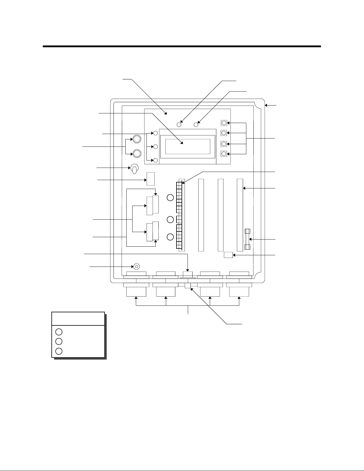
Internal Description
This section describes the internal components of the Pioneer.
Display screen
Alarm lights
(see Fig. 2-2)
AC fuses
(115V—1 amp top only)
(220V—1/2 amp both)
Power switch
AC terminal strip
External wiring
terminal strips (lower)
External wiring
terminal strips (upper)
Buzzer
(behind switch)
Ground stud
Transformer
(under display
screen board)
PILOT light
FAIL light
Housing
Program buttons
(see Fig. 2-2)
Analyzer card
Analyzer card
1.
socket (4)
2.
3.
DC fuse
(3A, 250V)
Expansion
terminal strip
Analyzer Card
terminal strips
Relay
1.
2.
Recorder output
3.
Detector
Conduit hubs
(3/4 in. NPT)
Reset switch
Figure 2-1: Pioneer Gas Monitor Component Location
4 • Description Pioneer Gas Monitor Operator’s Manual
Page 9

Fuses
The Pioneer includes up to two AC fuses and one DC fuse.
AC fuse(s)
Two AC fuse holders are above the power switch (near the upper left corner of the main
circuit board). The AC fuse(s) protects the AC line circuitry from short circuit or overload.
For a 115 VAC power source, a 1-amp fuse is installed in the top fuse holder. For a 220
VAC power source, two 1/2-amp fuses are installed in the top and bottom fuse holders.
NOTE:
DC fuse
The DC fuse is to the right of the fourth analyzer card socket (near the lower right corner
of the main circuit board). The DC fuse protects the DC line circuitry from short circuit or
overload. The DC fuse is rated at 3 amps.
The standard configuration is for 115 VAC operation. 220 VAC operation is an
optional configuration and must be specified when ordering.
Power Switch
The power switch is directly below the AC fuse. The power switch turns the incoming
power source on and off at the Pioneer. When the switch is up, the power switch is on. A
round polycarbonate guard is mounted to the switch bushing to protect against accidental
contact with live parts on the circuit board near the switch.
Transformer
The transformer is to the right of the AC fuse (under the display screen). The transformer
receives the incoming AC voltage and converts it to a nominal DC voltage.
Ground Stud
The ground stud extends from the bottom left corner of the main circuit board. Remove
the nut to install a ground wire terminated with a #10 lug, then replace the nut.
CAUTION: Do not use the GND terminal to connect the ground wire. Use the ground stud
described above.
Terminal Strips
The Pioneer includes four terminal strips for external wiring connections. See Chapter 3,
Installation and Start Up, for wiring procedures.
NOTE: The analyzer card also includes three terminal strips. They are described at the
end of this chapter.
AC terminal strip
The 3-point AC terminal strip is below and to the right of the power switch. You connect
the incoming AC power source to the AC terminal strip. The AC terminal strip is labeled
TB1 on the main circuit board. A polycarbonate terminal cover protects against
accidental contact with the live terminal screws once power to the unit is turned on.
Pioneer Gas Monitor Operator’s Manual Description • 5
Page 10

External wiring terminal strips
Two external wiring terminal strips are below the AC terminal strip and to the left of the
relays. Each 12-point terminal strip includes a lower (terminals 1 through 6) and upper
(terminals 7 through 12) row of terminals. The external wiring terminal strips are labeled
TB2 and TB3 on the main circuit board. Table 2-1 lists the function of the external wiring
terminal strips.
Table 2-1: Terminal Assignments for the External Wiring Terminal Strips
Terminal Number Wire to:
TB3
TB2
Expansion terminal strip
The 3-point expansion terminal strip is below and between the third and fourth analyzer
card sockets (near the bottom right corner of the main circuit board). You can network up
to four Pioneers together by using the expansion terminal strip. The expansion terminal
strip is labeled TB4 on the main circuit board.
1 Not currently used
2, 3 RS-485 connection to a personal computer (PC)
4 Shield
5, 6 RS-232 connection to a PC
7 - 9 External alarm for common alarm 3 relay
10 - 12 External alarm for common alarm 2 relay
1, 2 DC power source (Y ou can use DC power as a primary
or backup power source.)
3, 4 The buzzer (factory-wired)
5, 6 The reset switch (factory-wired)
7 - 9 External alarm for common alarm 1 relay
10 - 12 External alarm for common fail relay
Relays
NOTE: Each analyzer card also includes alarm 3, alarm 2, and alarm 1 relays that are
dedicated to the channel that the analyzer card is plugged into.
Four relays are to the right of the external wiring terminal strips. The relays are singlepole, double-throw (SPDT) and are rated for 8 amps at 250 VAC (resistive). The relays are
from top to bottom alarm 3, alarm 2, alarm 1, and fail. The relays are common for all
channels. For example, the alarm 1 relay energizes when any active channel goes into an
alarm 1 condition.
NOTE: You can select normally energized or normally de-energized relays in the
Instrument Setup program. This section describes the default setting: normally
de-energized. The fail relay is factory-set as normally energized and is not
user-selectable.
6 • Description Pioneer Gas Monitor Operator’s Manual
Page 11
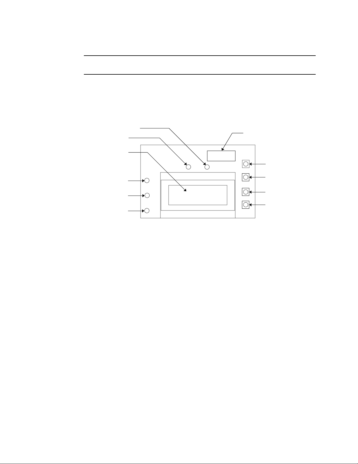
Display Screen
NOTE: The display screen, status lights, and program buttons are mounted to a small
circuit board. The circuit boar d is mounted to the main cir cuit board by standof fs.
The display screen is mounted to a circuit board that is installed in front of the main
circuit board. The display screen simultaneously displays the target gas, measuring unit,
and current gas reading of all active channels.
The display screen also displays messages, settings, and other data when you are
operating the instrument programs (see Chapter 4, Operation).
FAIL light
PILOT light
Display screen
ALARM 3 light
ALARM 2 light
ALARM 1 light
Data logging chip (optional)
ESCAPE button
UP/YES button
DOWN/NO button
ENTER button
Figure 2-2: Display Screen Component Location
Status Lights
The Pioneer includes six status lights that indicate the current status of the monitor.
POWER light
The POWER light is on the main circuit board near the top edge. The green POWER light
is on when the Pioneer has live power connected and the power switch is in the ON
position.
PILOT light
The PILOT light is above the display screen and to the left of the FAIL light. The green
PILOT light is on when the monitor is receiving incoming power. The PILOT light flashes
when the alarms are disabled. The alarms are disabled during instrument warm up and
when you enter one of the Pioneer’s various programs.
FAIL light
The FAIL light is above the display screen and to the right of the PILOT light. The FAIL
light turns on when the Pioneer is experiencing a fail condition. A fail condition can be
caused by a failure within the monitor or detector(s) wired to the monitor. See Chapter 5,
Maintenance, or the troubleshooting section in the applicable detection insert to respond
to a fail condition.
Pioneer Gas Monitor Operator’s Manual Description • 7
Page 12

ALARM 3 light
The ALARM 3 light is to the left of the display screen. The ALARM 3 light turns on when
the Pioneer is experiencing an alarm 3 condition (see Chapter 4, Operation).
ALARM 2 light
The ALARM 2 light is to the left of the display screen and below the ALARM 3 light. The
ALARM 2 light is on when the Pioneer is experiencing an alarm 2 or alarm 3 condition.
ALARM 1 light
The ALARM 1 light is to the left of the display screen and below the ALARM 2 light. The
ALARM 1 light turns on when the Pioneer is experiencing an alarm 1, alarm 2, or alarm 3
condition.
Program Buttons
The Pioneer includes four program button that allow you to enter the instrument
programs, navigate through the programs, update instrument and channel settings, and
save changes to the program settings.
ESCAPE button
The ESCAPE button is above and to the right of the display screen. Use the ESCAPE
button to:
• move backward through the instrument programs
• cancel changes you make in the instrument programs
• enter the Instrument Setup program (when pressed with the ENTER button)
UP/YES button
The UP/YES button is to the right of the display screen and below the ESCAPE button.
Use the UP/YES button to:
• change settings within the instrument programs
• enter the Calibration program (when pressed with the ENTER button)
DOWN/NO button
The DOWN/NO button is to the right of the display screen and below the UP/YES
button. Use the DOWN/NO button to:
• change settings within the instrument programs
• enter the Channel Setup program (when pressed with the ENTER button)
ENTER button
The ENTER button is to the right of the display screen and below the DOWN/NO button.
Use the ENTER button to:
• move forward through the instrument programs
• save changes you make in the instrument programs
• enter the Instrument Setup program (when pressed with the ESCAPE button)
• enter the Calibrate program (when pressed with the UP/YES button)
• enter the Channel Setup program (when pressed with the DOWN/NO button)
8 • Description Pioneer Gas Monitor Operator’s Manual
Page 13

Analyzer Card
The analyzer card plugs into one of four u-shaped sockets near the bottom right corner of
the main circuit board. Each channel of detection includes an analyzer card. The analyzer
card includes the detector terminal strip, analog output terminal strip, external alarms
terminal strip, pilot light, and three relays.
The terminals unplug from the terminal strips to give better access to the terminals when
you make wiring connections.
Detector terminal strip
The 7-point detector terminal strip (terminals 1 through 7) is the terminal strip closest to
the bottom of the analyzer card. You connect wiring from the detector to the detector
terminal strip.
NOTE: See the applicable detection insert in Appendix B, Gas Detectors, to wire the
detector to the analyzer card.
Analog Output terminal strip
The 2-point analog output terminal strip (terminals 8 and 9) is directly above the detector
terminal strip. You connect wiring from a recording device (if applicable) to the analog
output terminal strip.
The output at the analog output terminal strip is 4 to 20 mA or 0 to 1 V. The output is
selectable by jumpers on the analyzer card. The standard (default) output is 4 to 20 mA.
External alarms terminal strip
NOTE: The Pioneer also includes two common external alarm terminal strips. These
common terminal strips activate external alarms for all active channels.
The 9-point external alarm terminal strip is above the analog output terminal strip. You
connect wiring from external alarms (if applicable) to the external alarm terminal strip.
This terminal strip has common (C), normally closed (NC) and normally open (NO)
terminals for alarm 1, alarm 2, and alarm 3 connections.
Pilot light
The pilot light is between the external alarms terminal strip and analog output terminal
strip. The pilot light flashes when the analyzer card is receiving power and operating
normally. The pilot light does not flash or is off when a failure occurs.
Pioneer Gas Monitor Operator’s Manual Description • 9
Page 14

Relays
NOTE: The Pioneer also includes four common relays (to the left of the analyzer card
sockets). The common relays activate for all active channels.
Three relays are behind the external alarm terminal strip. The relays are single-pole,
double-throw (SPDT) and are rated for 8 amps at 250 VAC (resistive). The relays are from
top to bottom alarm 1, alarm 2, and alarm 3. The relays are dedicated to the channel that
the analyzer card is plugged into only. For example, the alarm 1 relay energizes only when
the channel that the card is plugged into goes into an alarm 1 condition.
NOTE: You can select normally energized or normally de-energized relays in the
Instrument Setup program. This section describes the default setting: normally
de-energized.
10 • Description Pioneer Gas Monitor Operator’s Manual
Page 15

Chapter 3: Installation and Start Up
Overview
This chapter describes procedures to mount the Pioneer Gas Monitor, make wiring
connections to the monitor, and start up the monitor.
WARNING: Perform all installation and start-up procedures in a “fresh air”
environment (known to be free of combustible gas, toxic gas, and of normal
oxygen content). The Pioneer is not in operation as a gas monitoring
system until the start-up procedure is complete.
Pioneer Gas Monitor Operator’s Manual Installation and Start Up • 11
Page 16
Mounting the Pioneer Gas Monitor
Perform the following procedure to install the instrument housing at the mounting site.
1. Select the mounting site. When you select the mounting site consider the following
factors:
• Is an AC or DC power source available?
• Is there enough room to open the housing door and make wiring connections
through the conduit hubs at the bottom of the housing?
• Are the display screen and status lights visible?
2. If necessary, close and latch the housing door.
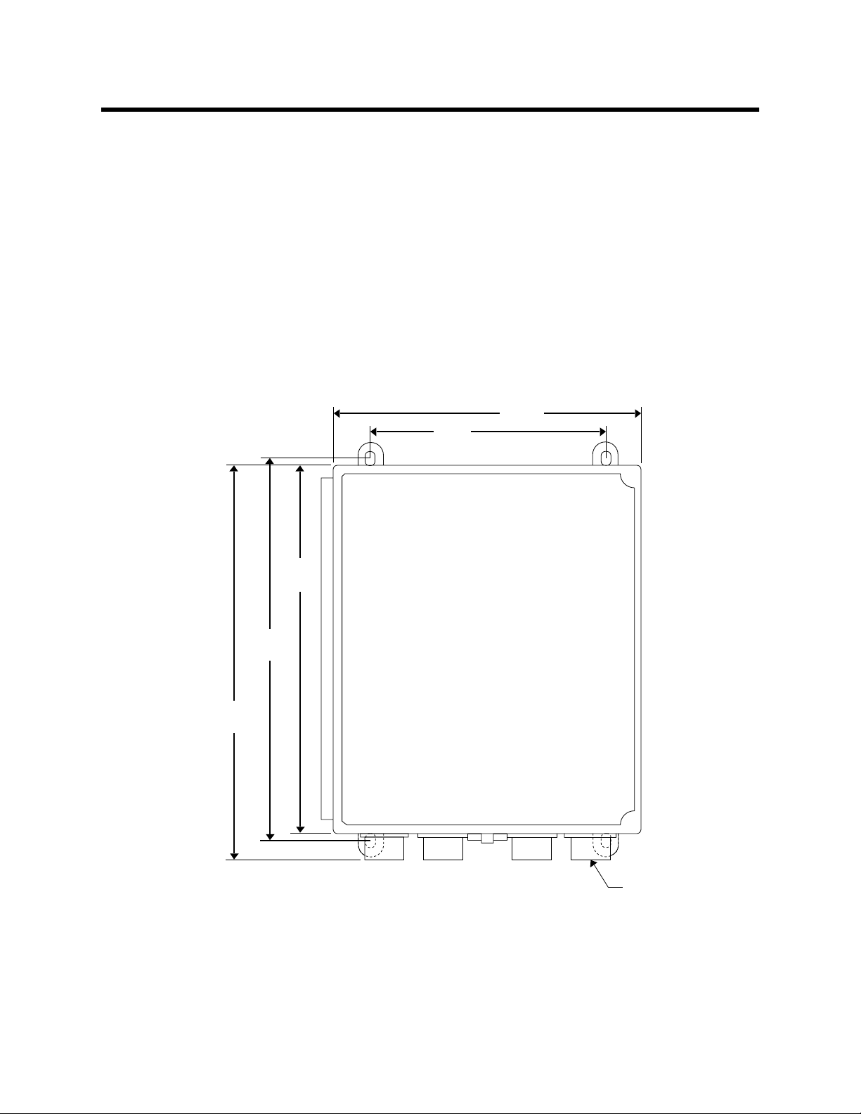
3. Position the monitor on a vertical surface at eye level (4 1/2 to 5 feet from the floor).
4. Insert 1/4 in. or 5/16 in. screws through the slots in the mounting feet at each corner
of the housing to secure the housing to the mounting surface (see Figure 3-1).
10.5 in.
8.0 in.
13.4
in.
12.5
in.
12.9
in.
3/4 in. conduit hub
(total of 4 hubs)
Note: The housing is 6.25 in. deep.
Figure 3-1: Pioneer Gas Monitor Outline and Mounting Dimensions
12 • Installation and Start Up Pioneer Gas Monitor Operator’s Manual
Page 17
9
C
NC
NO
NO
INDIVIDUAL ALARM 1
C
C
NC
ALARM 2 ALARM 1
INDIVIDUAL ALARM 2
NC
NO
ALARM 3
INDIVIDUAL ALARM 1
+
ANALOG OUTPUT
+
4 to 20 mA
RECORDER
(SEE MANUAL FOR OTHER OUTPUTS)
FOR EACH SET OF ALARM RELAYS CONTACTS.
CONTACT RATING OF 8 AMPS RESISTIVE AT 24VDC
ALARM 3
COMMON
8
-
-
4 to 20 mA
4 to 20 mA
ALARM 2
COMMON
7
6
GROUND
24V
(3-wire type)
Sensor/Transmitter
(2-wire type)
Sensor/Transmitter
ALARM 1
COMMON
5
4-20
4
3
RED
WHITE
COMMON
FAIL ALARM
2
1
GREEN
BLACK
(typical wiring)
AND HOUSING
OXYGEN SENSOR
green
-
+
white
white
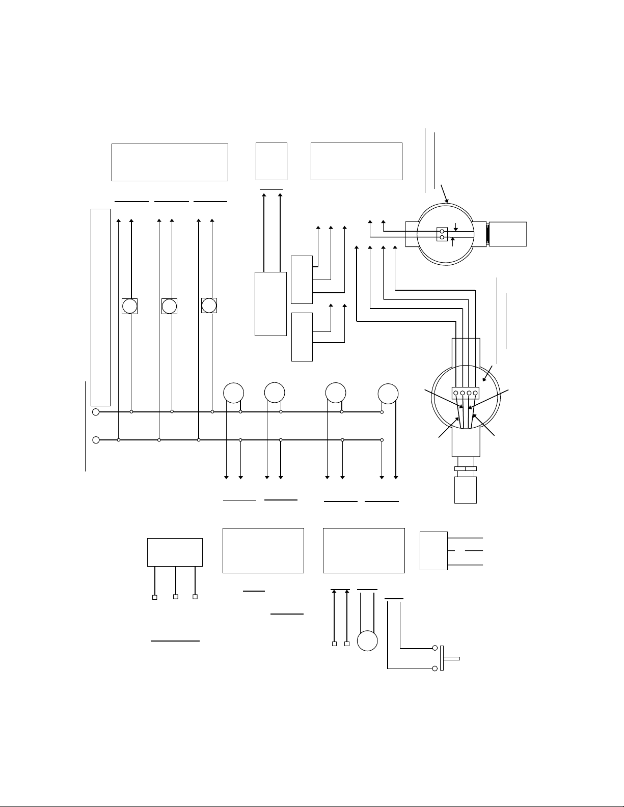
NOTE 3: See Appendix B
for other detection types.
(typical wiring)
AND HOUSING
COMBUSTIBLE SENSOR
green
ALARM DEVICE POWER
1
of main circuit board.
NOTE 1: Connect ground wire to
ground stud on lower left corner
GROUND
AC POWER
3
2
HOT
NEUTRAL
connection)
(see manual
for 230VAC
115V, 60 HZ.
ALARM 3
COMMON
NC
NO
C
NO
C
7
18293104115126
-
+
SHIELD
RS 485
(see manual)
NO CONNECTION
ALARM 2
COMMON
NC
RX
TX
RS 232
(see manual)
C
NO
7
8
1
+
24 VDC
-
+
STANDBY
DC POWER
ALARM 1
COMMON
NC
9
2
3
-
+
INTERNAL
FAIL
C
NO
10
11
4
5
NO
BUZZER
BUZZER
COMMON
NC
12
321
6
-
RESET
red
SDA
CLK GND
RESET
SWITCH
black
(see manual)
EXPANSION
(internal)
Figure 3-2: Pioneer Gas Monitor External Wiring Diagram
NOTE 2: The internal buzzer and
reset switch are factory-wired.
Pioneer Gas Monitor Operator’s Manual Installation and Start Up • 13
Page 18

Wiring the Pioneer Gas Monitor
This section describes procedures to connect the AC power source, DC power source,
external alarm(s), recorder, and detector(s). See Figure 3-2 for a general wiring diagram of
all external wiring to the Pioneer.
conduit plugs in all unused conduit hubs. See Appendix A. Parts List, for ordering information.
W ARNING: Make all connections to the Pioneer befor e you plug in or turn on the AC or
DC power source. Before you make any wiring adjustments, always verify
that all power sources are not live.
Connecting the AC Power Source
After completing all wiring connections, install 3/4 in. NPT
NOTE:
If you are using DC power as the primary power source, go to the next section,
“Connecting the DC Power Source” on page 15.
Perform the following procedure to connect the AC power source to the Pioneer.
WARNING: Verify that the power source is unplugged or turned off at the power source
end before you continue with this procedure.
1. Open the housing door , and locate the AC terminal strip (TB1). See Figure 2-1, Pioneer
Gas Monitor Component Location, to assist you in locating the AC terminal strip.
2. Remove the AC terminal cover by removing the two screws that retain it.
3. Guide the AC power cord through the leftmost conduit hub on the bottom of the
Pioneer housing.
CAUTION: Do not route power and detector wiring through the same conduit hub. The power
wiring may disrupt the transmission of the detector signal to the monitor.
4. Connect the AC line to the AC terminal strip as shown in Figure 3-3. (Connect the
ground wire to the ground stud on the lower left corner of the main circuit board.)
5. Replace the AC terminal cover.
(factory-wired) Ground
Neutral
Hot
1
2
3
AC Power
Source
AC Terminal Strip
Figure 3-3: AC Power Wiring
14 • Installation and Start Up Pioneer Gas Monitor Operator’s Manual
Page 19

Connecting the DC Power Source
WARNING: Verify that the power source is unplugged or turned off at the power source
end before you continue with this procedure.
Perform the following procedure to connect the DC power source to the Pioneer.
NOTE: A jumper block located at the middle upper edge of the main circuit board
allows you to configure the Pioneer to operate from either 12 VDC or 24 VDC.
To select 12 VDC operation (input range of 11 to 22 VDC), install the jumper
block over the right two pins. To select 24 VDC operation (input range of 23 to
60 VDC), install the jumper block over the left two pins. The factory default
configuration is for 24 VDC operation.
1. Open the housing door, and locate the bottom external wiring terminal strip (TB2).
See Figure 2-1, Pioneer Gas Monitor Component Location, to assist you in locating the
bottom external wiring terminal strip.
2. Guide a DC power cord through one of the conduit hubs on the bottom of the Pioneer
housing.
CAUTION: Do not route power and detector wiring through the same conduit hub. The power
wiring may disrupt the transmission of the detector signal to the monitor.
3. Connect the DC line to the lower row of terminals on the external wiring terminal
strip as shown in Figure 3-4.
+
1
2
-
DC Power
Source
Figure 3-4: DC Power Wiring
External Wiring
Terminal Strip (TB2)
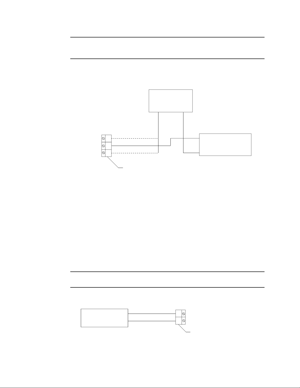
Connecting External Alarms
Perform the following procedure to connect external alarms to the Pioneer.
NOTE: The analyzer card includes external alarm connections that are dedicated to the
applicable channel only. See Appendix B, Gas Detectors, to wire external alarms
to the analyzer card.
1. Open the housing door, and locate the external wiring terminal strips (TB2 and TB3).
See Figure 2-1, Pioneer Gas Monitor Component Location, to assist you in locating the
external wiring terminal strips.
2. Guide the wiring of the external alarm through one of the conduit hubs on the bottom
of the Pioneer housing.
Pioneer Gas Monitor Operator’s Manual Installation and Start Up • 15
Page 20
or
CAUTION: If the external alarm device is powered by AC current, do not route the external
alarm wiring and detector wiring through the same conduit hub. The external alarm
wiring may disrupt the transmission of the detector signal to the Pioneer.
3. Connect the leads from the external alarm to the terminals on the appropriate external
wiring terminal strip as shown in Figure 3-5. See Table 2-1, Terminal Assignments for
the External Wiring Terminal Strips, to determine the applicable external alarm
terminals.
External
Power Source
+ (H)
NO
COM
NC
External Wiring
Terminal Strip (TB2, TB3)
— (N)
+ (H)
— (N)
External
Alarm Device
Figure 3-5: External Alarm Wiring
4. Repeat steps 2 and 3 for additional external alarms.
Connecting Recorders
Perform the following procedure to connect a recor ding device to the Pioneer. The output
at the analyzer card’s analog output terminal strip is a 4 to 20 mA
proportional to the detection range of the applicable detector. Unless specified, the
analyzer card is set up at the factory for 4 to 20 mA output.
1. Open the housing door, and locate the analog output terminal strip on the applicable
analyzer card. (The analog output terminal strip is the 2-point terminal strip between
the detector terminal strip and the external alarm terminal strip.)
0 to 1 V signal that is
2. Guide the wiring from the recording device through one of the conduit hubs on the
bottom of the Pioneer housing.
CAUTION: Do not route power and detector wiring through the same conduit hub. The power
wiring may disrupt the transmission of the detector signal to the monitor.
3. Connect the leads from the recording device to the analog output terminal strip as
shown in Figure 3-6.
Recording
Device
+
—
9
(Rec Out +)
8
(Rec Out -)
Analog Output Terminal Strip
(on analyzer card)
Figure 3-6: Recorder Output Wiring
16 • Installation and Start Up Pioneer Gas Monitor Operator’s Manual
Page 21

Connecting RKI Detectors
See the manual insert(s) in Appendix B, Gas Detectors, to wire the detector(s) supplied by
RKI Instruments, Inc., to the Pioneer.
Connecting User-Supplied 4 to 20 mA Transmitters
NOTE: : See the manual insert, “Generic 4 to 20 mA Transmitter,” in Appendix B,
Gas Detectors, for more detailed information related to the use of user-supplied
4 to 20 mA transmitters with the Pioneer.
Perform the following procedure to connect a 4 to 20 mA transmitter (that you supply) to
the Pioneer.
1. Open the housing door, and locate the detector terminal strip on the applicable
analyzer card. (The detector terminal strip is the 7-point terminal strip that is below
the analog output terminal strip.)
2. Route the cable leading from the transmitter through one of the conduit hubs on the
bottom of the Pioneer housing.
Transmitter
(+)
(-)
(FB)
CAUTION: Do not route power and transmitter wiring through the same conduit hub. The
power wiring may disrupt the transmission of the transmitter’s signal to the
Pioneer.
3. Connect the wires to the detector terminal strip of the applicable analyzer card as
shown in Figure 3-7. The detector is the 7-point terminal strip (terminals 1 through 7)
on the card.
3-Wire Connection
7 Gnd
6 24 V
5 4-20
4 RED
3 WHT
2 GRN
1 BLK
Detector
Terminal Strip
(+)
(-/FB)
Transmitter
2-Wire Connection
Detector
Terminal Strip
7 Gnd
6 24 V
5 4-20
4 RED
3 WHT
2 GRN
1 BLK
Figure 3-7: Generic 4 to 20 mA Transmitter Output Wiring
Pioneer Gas Monitor Operator’s Manual Installation and Start Up • 17
Page 22

Starting Up the Pioneer Gas Monitor
Perform the following procedure to place the Pioneer into normal operation.
1. Complete the mounting and wiring procedures described earlier in this chapter.
2. Complete all installation procedures described in Appendix B, Gas Detectors.
3. Verify that all wiring connections are correct and secure and the Pioneer’s power
switch is in the OFF position.
4. Plug in or turn on the incoming power source (AC or DC) at the power source end.
5. Place the Pioneer’s power switch in the ON position.
NOTE: To prevent unwanted alarms during warm up, the alarm circuits are not active
for 20 seconds to 2 minutes (depending on warm up) from the time you turn the
power switch on.
6. Verify the following:
• The PILOT light above the display screen is on.
• The POWER light on the main circuit board is on.
• The pilot light on each analyzer card is flashing.
If the pilot lights are not on or flashing, see the troubleshooting guides in Chapter 5,
Maintenance, and Appendix B, Gas Detectors.
7. Perform the start-up procedure for each detector as described in Appendix B,
Gas Detectors.
18 • Installation and Start Up Pioneer Gas Monitor Operator’s Manual
Page 23

Chapter 4: Operation
Overview
This chapter describes the Pioneer Gas Monitor in normal operation. This chapter also
describes the Pioneer in alarm 1, alarm 2, alarm 3, and fail conditions and suggests
response to these conditions. The Instrument Setup program and Display Setpoints and
Readings program are described at the end of this chapter.
Normal Operation
Normal operation is defined as follows:
• the start-up procedure is complete.
• the Pioneer is not indicating an alarm 1, alarm 2, alarm 3, or fail condition.
• the Pioneer is not running the Instrument Setup, Channel Setup, Calibrate, or
Display Setpoints and Readings program.
During normal operation, the Pioneer simultaneously displays the target gas, unit of
measure, and current gas reading for all active channels. The Pioneer displays the
readings horizontally for each channel. If all four channels are installed, channel 1 is the
top reading, and channel 4 is the bottom reading.
The PILOT light near the display screen, the POWER light on the main circuit board, and
the pilot light on each analyzer card are on during normal condition indicating that the
monitor and analyzer cards are receiving incoming power. The output at terminals 8 and 9
of the analyzer card’s output terminal strip is 4 to 20 mA
the detection range of the detector that is wired to the analyzer card. (The standard output
at terminals 8 and 9 is 4 to 20 mA.)
Alarm Indications
This section describes the Pioneer in alarm 1, alarm 2, alarm 3, and fail conditions and
suggests response to these conditions. Table 4-1 lists the alarm indications for each
condition.
C
H1
C
H2
CH3
C
H4
20.
0
9
0
0
%L
E
VOL
%
M
PP
PPM
L
COMB
OXY
CO
S
H2
or
0 to 1 V and is proportional to
NOTE:
Pioneer Gas Monitor Operator’s Manual Operation • 19
The Pioneer includes alarm on and alarm off delay settings. The alarm
indications described in this section operate according to the default delay
settings. See the Channel Setup program section in the applicable detection insert
(Appendix B, Gas Detectors) to display or change the alarm on and alarm off
delay settings.
Page 24

Table 4-1: Visual and Audible Alarm Indications
Condition Cause Visual Indication
Alarm 1 Increasing (decreasing for O2) gas reading
at or above the alarm 1 setpoint
Alarm 2 Increasing (decreasing for O2) gas reading
at or above the alarm 2 setpoint
• ALARM 1 light is on
• Gas reading flashes
• ALARM 1 and ALARM 2
lights are on
• Gas reading flashes
Alarm 3 Increasing gas reading at or above the
alarm 3 setpoint
• ALARM 1, ALARM 2,
and ALARM 3 lights are
on*
• Gas reading flashes
Fail • Disconnected or misconnected
• FAIL light is on Steady tone
detector wiring
• Disconnected or misconnected
analyzer card
• Display reading below fail setpoint
• Defective components
* The ALARM 1 and ALARM 2 lights are not on for oxygen channels.
Audible
Indication
Pulsing tone
Faster
pulsing tone
than Alarm 1
Faster
pulsing tone
than Alarm 2
NOTE:
You can select normally energized or normally de-energized relays in the
Channel Setup program. The following sections describe the default setting for
the relays: normally de-energized. The fail relay is factory-set for normally
energized and is not user-selectable.
Alarm 1 Condition
This section describes the audible and visual indications for an alarm 1 condition and
suggests response to an alarm 1 condition.
Alarm 1 condition indications
When the gas reading of an active channel reaches the alarm 1 setpoint, the Pioneer senses
an alarm 1 condition. The Pioneer alerts you to an alarm 1 condition as follows:
• the ALARM 1 light turns on
• the gas reading in alarm 1 condition flashes
• the buzzer sounds a pulsing tone
• the common alarm 1 relay energizes
• the alarm 1 relay on the applicable analyzer card energizes
Responding to an alarm 1 condition
This section suggests response to an alarm 1 condition.
1. Follow your established procedure for a low level combustible or toxic gas condition
or a decreasing oxygen content condition.
20 • Operation Pioneer Gas Monitor Operator’s Manual
Page 25

2. After the gas reading falls below the alarm 1 setpoint, press the reset switch to reset
the alarm 1 circuit. Resetting the alarm 1 circuit silences the buzzer, turns off the
ALARM 1 light, and de-energizes the common and analyzer card alarm 1 relays.
NOTE: To silence the buzzer while in an alarm 1 condition, press the reset switch.
You cannot de-energize the alarm 1 relays until the gas reading falls below
(above for oxygen) the alarm 1 setpoint.
Alarm 2 Condition
This section describes the audible and visual indications for an alarm 2 condition and
suggests response to an alarm 2 condition.
Alarm 2 condition indications
When the gas reading of an active channel reaches the alarm 2 setpoint, the Pioneer senses
an alarm 2 condition. The Pioneer alerts you to an alarm 2 condition as follows:
• the ALARM 2 light turns on
• the gas reading in alarm 2 condition continues to flash
• the buzzer sounds a faster pulsing tone than an alarm 1 condition
• the common alarm 2 relay energizes
• the alarm 2 relay on the applicable analyzer card energizes
Responding to an alarm 2 condition
This section suggests response to an alarm 2 condition.
1. Follow your established procedure for a mid level combustible or toxic gas condition
or a severe decreasing oxygen content condition.
2. After the gas reading falls below the alarm 2 setpoint, press the reset switch to reset
the alarm circuit. Resetting the alarm circuit turns off the ALARM 2 light, and
de-energizes the common and analyzer card alarm 2 relays.
NOTE: To silence the buzzer while in an alarm 2 condition, press the reset switch.
You cannot de-energize the alarm 2 relays until the gas reading falls below
(above for oxygen) the alarm 2 setpoint.
Alarm 3 Condition
This section describes the audible and visual indications for an alarm 3 condition and
suggests response to an alarm 3 condition.
Alarm 3 condition indications
When the gas reading of an active channel reaches the alarm 3 setpoint, the Pioneer senses
an alarm 3 condition. The Pioneer alerts you to an alarm 3 condition as follows:
• the ALARM 3 light turns on
• the gas reading in alarm 3 condition continues to flash (the gas reading for O
channels begins flashing)
• the buzzer sounds a faster pulsing tone than an alarm 1 or alarm 2 condition
• the common alarm 3 relay energizes
• the alarm 3 relay on the applicable analyzer card energizes
Pioneer Gas Monitor Operator’s Manual Operation • 21
2
Page 26

NOTE: The alarm 3 relay does not energize if you elect to use it as the channel’s fail relay
in the Channel Setup program (see the “Channel Setup Program” section of the
applicable detection insert in Appendix B, Gas Detectors.)
Responding to an alarm 3 condition
This section suggests response to an alarm 3 condition.
1. Follow your established procedure for a high level combustible or toxic gas condition
or an increasing oxygen content condition.
2. After the gas reading falls below the alarm 3 setpoint, press the reset switch to reset
the alarm 3 circuit. Resetting the alarm 3 circuit turns off the ALARM 3 light, and
de-energizes the common and analyzer card alarm 3 relays.
NOTE: To silence the buzzer while in an alarm 3 condition, press the reset switch.
You cannot de-energize the alarm 3 relays until the gas reading falls below the
alarm 3 setpoint.
Fail Condition
This section describes the audible and visual indications for a fail condition and suggests
response to a fail condition.
Fail condition indications
The Pioneer senses a fail condition for any of the following:
• the detector wiring is disconnected or incorrectly connected
• the analyzer card is disconnected or incorrectly connected
• the display reading is below the fail setpoint
• the monitor or detector is malfunctioning
When the Pioneer senses a fail condition, it alerts you as follows:
• the FAIL light turns on
• the gas reading in fail condition flashes
• the buzzer sounds a steady tone
• the common fail relay de-energizes
NOTE: If you elected to use the analyzer card’s alarm 3 relay as an individual fail relay
in the Channel Setup program, the relay de-energizes in a fail condition.
(See the “Channel Setup Program” section of the applicable detection insert in
Appendix B, Gas Detectors.)
Responding to a fail condition
This section suggests response to a fail condition.
1. Verify that the detector wiring is correctly and securely connected.
2. Verify that the analyzer card is securely and correctly installed. (The components of
the analyzer card face left when the analyzer card is correctly installed.)
3. See the troubleshooting guide in the applicable detection insert (Appendix B,
Gas Detectors).
22 • Operation Pioneer Gas Monitor Operator’s Manual
Page 27

Instrument Setup Program
This section describes the Instrument Setup program. You can display and change the
following instrument settings with the Instrument Setup program.
• Alarm On Delay
• Alarm Off Delay
• Relay Action
• Alarm Logic
• Alarm Silence
• Alarm Hysteresis
• Calibration Time Out
• Instrument ID (RS-232 or RS-485 address)
• Noise Filter
• Maximum Number of Channels (for use when connecting to other Pioneers)
• Zero Suppression
• Instrument Label
Navigating through the Instrument Setup Program
Use the program buttons to the right of the display screen to enter the program, move
forward or backward through the pr ogram, change settings within the pr ogram, and save
or cancel changes to the program settings. Table 4-2 lists the function of each program
button.
Table 4-2: Program Button Functions for the Instrument Setup Program
Button Function
ESCAPE • Moves you backward through the program
• Cancels changes made to the program settings
• Enters the program (with the ENTER button)
UP/YES • Updates the setting that is flashing on the
display screen
DOWN/NO • Updates the setting that is flashing on the
display screen
ENTER • Moves you forward through the program
• Saves changes made to the program settings
• Enters the program (with the ESCAPE button)
Pioneer Gas Monitor Operator’s Manual Operation • 23
Page 28

Running the Instrument Setup Program
This section describes how to enter the program, display and change program settings,
and save or cancel changes to the program settings.
Entering the instrument setup program
1. Open the housing door, and locate the program buttons to the right of the display
screen.
2. Press the ENTER and ESCAPE buttons simultaneously three times.
The display screen indicates that you are in the Instrument Setup program.
3. Press the ENTER, UP/YES, or DOWN/NO button to continue.
The program displays the Alarm ON Delay screen.
Alarm on delay screen
This screen indicates the length of time that the Pioneer delays alarm indications (buzzer
and relays) when it senses an alarm 1, alarm 2, or alarm 3 condition. You can choose from
a range of 0 Seconds to 60 Minutes. The default setting is
0 Minutes, 1 Seconds .
Alarm
0
1
• To accept the alarm on delay setting and continue the program, press the ENTER
button.
The program displays the Alarm OFF Delay screen.
• To update the alarm on delay setting:
1. Use the UP/YES and DOWN/NO buttons to display the setting you want.
2. Press the ENTER button to continue the program.
The program displays the Alarm OFF Delay screen.
Alarm off delay screen
This screen indicates the length of time that the Pioneer delays turning off alarm
indications (buzzer and relays) after an alarm 1, alarm 2, or alarm 3 condition passes. You
can choose from a range of 0 Seconds to 60 Minutes. The default setting is 0 Minutes,
0 Seconds .
Alarm
0
0S
O
NDel
Minutes
S
econds
O
F
F
Minutes
econds
ay:
De lay :
• To accept the alarm off delay setting and continue the program, press the ENTER
button.
The program displays the Relay Action screen.
• To update the alarm off delay setting:
1. Use the UP/YES and DOWN/NO buttons to display the setting you want.
2. Press the ENTER button to continue the program.
The program displays the Relay Action screen.
24 • Operation Pioneer Gas Monitor Operator’s Manual
Page 29

Relay action screen
This screen indicates how the relays operate in normal and alarm conditions. If the setting
is NORMALLY DE-ENERGIZED , the relays energize in alarm conditions. If the setting is
NORMALLY ENERGIZED , the relays de-energize in alarm conditions. The default
setting is NORMALLY DE-ENERGIZED .
NOTE: The common fail relay and channel fail relay (if assigned) are not af fected by this
setting. Fail relay(s) are factory-set as normally energized and are not adjustable.
RELAYSNORALLY
DE-NERGIZED
E
M
• To accept the relay action setting and continue the program, press the ENTER button.
The program displays the Alarm Logic screen.
• To update the relay action setting:
1. Use the UP/YES or DOWN/NO button to display the setting you want.
2. Press the ENTER button to continue the program.
The program displays the Alarm Logic screen.
Alarm logic screen
This screen indicates how an alarm circuit is reset after the applicable alarm condition
passes. If the setting is LATCHING , you must press the reset switch after the alarm
condition passes to reset the alarm circuit. If the setting is AUTO-RESET , the alarm circuit
is automatically reset after the alarm condition passes. The default setting is LATCHING .
S
ALAR
L
M
C
A
HIN
T
G
• To accept the alarm logic setting and continue the program, press the ENTER button.
The program displays the Alarm Silence screen.
• To update the alarm logic setting:
1. Use the UP/YES or DOWN/NO button to display the setting you want.
2. Press the ENTER button to continue the program.
The program displays the Alarm Silence screen.
Pioneer Gas Monitor Operator’s Manual Operation • 25
Page 30

ON
Alarm silence screen
This screen indicates how the buzzer operates during alarm conditions. If the setting is
, you can use the reset switch to silence the buzzer during alarm conditions. If the
setting is OFF , you cannot silence the buzzer until all alarm conditions pass. The default
setting is ON .
ARM
AL E E
O
N
S
LCIN
• To accept the alarm silence setting and continue the program, press the ENTER
button.
The program displays the Alarm Hysteresis screen.
• To update the alarm silence setting:
1. Use the UP/YES or DOWN/NO button to display the setting you want.
2. Press the ENTER button to continue the program.
The program displays the Alarm Hysteresis screen.
Alarm hysteresis screen
This screen indicates when the Pioneer considers an alarm condition passed. The alarm
hysteresis feature helps prevent readings that are near an alarm setpoint from frequently
going into and out of alarm (relay chattering). For example, if the alarm hysteresis setting
is 2.0% of fullscale, fullscale is 10.0 ppm, and the alarm 1 setpoint is 3.0 ppm; then the
Pioneer will not consider the alarm 1 condition “passed” until the reading goes below 2.8
ppm. You can choose from a range of 0.0% to 10.0% of fullscale (in 0.1% increments). The
default setting is 2.0% .
L
SC
S
ALE
ALAR HMYSTRESI
%
0
2.
O
E
U
F
L
F
• To accept the alarm hysteresis setting and continue the program, press the ENTER
button.
The program displays the Calibration Time Out screen.
• To update the alarm hysteresis setting:
1. Use the UP/YES or DOWN/NO button to display the setting you want.
2. Press the ENTER button to continue the program.
The program displays the Calibration Time Out screen.
26 • Operation Pioneer Gas Monitor Operator’s Manual
Page 31

Calibration time out screen
The Pioneer’s Calibrate program includes two separate time-out features. The first
time-out feature is a general 5-minute time-out. The Pioneer automatically returns to the
normal screen if you do not move from one Calibrate screen to another within 5 minutes.
You cannot adjust this setting, and it affects all Calibrate screens except the Fresh Air and
Calibration screens.
The second time-out feature affects the Fresh Air and Calibration screens only. These are
the screens you use during calibration to adjust the zero and span readings (either at the
transmitter or the Pioneer). The Pioneer automatically returns to the normal screen if you
do not move from the Fresh Air or Calibration scr een within the time-out setting specified
in the screen below. You can choose from a range of 10 to 100 minutes (in increments of
10). The default setting is
10 Minutes .
Ca
libr
Tim
10
atio
e-Ou t
nMenu
:
Minu
tes
• To accept the calibration time out setting and continue the program, press the ENTER
button.
The program displays the Instrument ID screen.
• To update the calibration time out setting:
1. Use the UP/YES or DOWN/NO button to display the setting you want.
2. Press the ENTER button to continue the program.
The program displays the Instrument ID screen.
Instrument ID screen
This screen indicates the ID number (address) for this Pioneer. The instrument ID is
recorded in the datalog when the datalog records instrument readings. This setting is
useful if you have more than one Pioneer networked together. You can choose from a
range of 1 to 255. The default setting is 1 .
INSTRUMENT ID FOR
RS232&RS4
85
:1
• To accept the instrument ID setting and continue the program, press the ENTER
button.
The program displays the Noise Filter screen.
• To update the instrument ID setting:
1. Use the UP/YES or DOWN/NO button to display the setting you want.
2. Press the ENTER button to continue the program.
The program displays the Noise Filter screen.
Pioneer Gas Monitor Operator’s Manual Operation • 27
Page 32

Noise filter screen
This screen indicates the length of time that the Pioneer averages data. You can choose
from a range of 0.5 to 15.0 seconds (in increments of 0.5). The default setting is 2.5
Seconds .
Filter
se
Noi
Soe
c
n
ds
5
2
.
NOTE: The Pioneer continuously displays gas readings although it averages gas
readings according to the noise filter setting.
• To accept the noise filter setting and continue the program, press the ENTER button.
The program displays the Number of Channels screen.
• To update the noise filter setting:
1. Use the UP/YES or DOWN/NO button to display the setting you want.
2. Press the ENTER button to continue the program.
The program displays the Number of Channels screen.
Number of channels screen
This screen indicates the maximum number of channels possible for the Pioneer. The
settings are displayed in multiples of 4. For example, if you have three Pioneers
networked together, select a setting of 12. You can choose from a range of 4 to16 (in
increments of 4). The default setting is 4 .
Chans
Max
m
of
#imu
:
4
• To accept the number of channels setting and continue the program, press the ENTER
button.
The program displays the Zero Suppression screen.
• To update the number of channels setting:
1. Use the UP/YES or DOWN/NO button to display the setting you want.
2. Press the ENTER button to continue the program.
The program displays the Zero Suppression screen.
28 • Operation Pioneer Gas Monitor Operator’s Manual
Page 33

Zero suppression screen
This screen indicates the zero suppression for the Pioneer. The zero suppression feature
helps prevent “jumpy” readings near the normal reading. For example, if the zero
suppression setting is 2.0% of fullscale and fullscale is 10.0 ppm, then the Pioneer will
display a reading of 0.0 ppm for gas readings from -0.2 to 0.2 ppm. You can choose from a
range of 0.0% to 5.0% (in 0.1% increments). The default setting is 2.0% .
ZER
2.
OUS
%
0
E
PPR SSI
O
U
F
F
O
N
SC
L
L
ALE
• To accept the zero suppression setting and continue the program, press the ENTER
button.
The program displays the Instrument Label screen.
• To update the zero suppression setting:
1. Use the UP/YES or DOWN/NO button to display the setting you want.
2. Press the ENTER button to continue the program.
The program displays the Instrument Label screen.
Instrument label screen
This screen indicates the identifying label for this Pioneer. The instrument label is
recorded in the datalog when the datalog records instrument readings. This setting is
useful if you have more than one Pioneer networked together. You can choose a label of
up to 15 characters. Characters can be letters, numbers, symbols, or blank spaces. The
default setting is RKI INSTRUMENTS .
In
RK
st
I
ent
rum
Label
INSTRUMENT
S
• To accept the instrument label setting and continue the program, press the ENTER
button until the Instrument Setup Exit screen displays.
• To update the instrument label setting:
1. Use the ENTER button to select the character you want to change. (The character
flashes when it is selected.)
2. Press the UP/YES or DOWN/NO button to display the character you want, then
press the ENTER button to select the next character.
3. Repeat steps 1 and 2 until the label is correct, then press the ENTER button until
the Instrument Setup Exit screen displays.
Pioneer Gas Monitor Operator’s Manual Operation • 29
Page 34

Instrument setup exit screen
This screen saves or cancels any changes you made in the Instrument Setup program.
APE
=
=
reviou
P
StoreSet-Up
E
SC
NTER
E
• To save changes and exit the program, press the ENTER button.
A confirmation message displays, then the normal screen displays. The Pioneer is in
normal operation.
• To cancel changes and exit the program, press the ESCAPE button until the following
message displays: “INSTRUMENT SET-UP NOT SAVED. USING PREVIOUS
VALUES.”
The normal screen displays. The Pioneer is in normal operation.
Display Setpoints and Readings Program
This section describes the Display Setpoints and Readings program. You can display the
following in this program. (You can also allow the Pioneer to perform a self check
procedure and reset the minimum and maximum readings in this program.)
• Software versions
• Time Weighted Average (TWA) and Short Term Exposure Limit (STEL) readings
(for applicable channels)
s
• Minimum and maximum readings (for each channel)
• Alarm Sets (for each channel)
Navigating through the Display Setpoints and Readings Program
Use the reset switch to begin the program, display the setpoints and readings, and exit the
program.
NOTE: This is a display only program. You cannot change settings or gas readings in the
Display Setpoints and Readings program.
Running the Display Setpoints and Readings Program
This section describes how to display the various setpoints and gas readings that are
included in this program. This section also describes how to display the time and date and
begin the self check procedure.
NOTE: Once you display one of the screens, the Pioneer automatically returns to the
normal screen in 1 minute if you do not continue or exit the program.
30 • Operation Pioneer Gas Monitor Operator’s Manual
Page 35

To display software versions:
The Display Setpoints and Readings program displays the version number of the
Pioneer’s instrument, display, and channel software programs.
1. Press and hold down the reset switch to enter the program.
2. When the DISPLAY VERSIONS screen appears, release the reset switch.
3. Press and release the reset switch to display the remaining software versions and
return to the normal screen.
To display TWA and STEL readings:
The Pioneer continuously computes Time Weighted Average (TWA) and Shot Term
Exposure Limit (STEL) readings for all active channels.
NOTE: The Pioneer does not calculate or display TWA and STEL setting for oxygen
channels or combustible gas channels that have a unit of measure setting of
%LEL . However, the Pioneer does calculate and display TWA and STEL settings
for combustible gas channels that have a unit of measure setting of PPM/LEL .
The STEL reading represents a channel’s average gas readings for the past 15 minutes.
The TWA reading represents a channel’s average gas readings for the past 8 hours.
1. Press and hold down the reset switch to enter the program.
2. When the DISPLAY TW A/STEL screen appears on the display scr een, release the r eset
switch.
The STEL reading displays for the first active channel.
3. Press and release the reset switch to display the TWA reading for the first active
channel.
4. Continue pressing and releasing the reset switch to display the STEL and TWA
readings for the remaining channels.
5. Press and release the reset switch to return to the normal screen.
To display minimum and maximum readings:
The Pioneer stores the minimum and maximum reading for all active channels since the
last time the minimum and maximum readings were reset.
1. Press and hold down the reset switch to enter the program.
2. When the DISPLAY MIN/MAX screen appears on the display screen, release the reset
switch.
The minimum reading displays for the first active channel.
3. Press and release the reset switch to display the maximum reading for the first active
channel.
4. Continue pressing and releasing the reset switch to display the minimum and
maximum readings for the remaining channels.
5. Press and release the reset switch to return to the normal screen.
Pioneer Gas Monitor Operator’s Manual Operation • 31
Page 36

To display alarm sets:
The Display Setpoints and Readings program displays the alarm sets for all active
channels. The alarm sets include the alarm logic, alarm silence, alarm setpoint, and alarm
type settings.
NOTE: You can change the alarm logic and alarm silence settings in the Instrument
Setup program. You can change the alarm setpoint and alarm type settings in the
Channel Setup program.
1. Press and hold down the reset switch to enter the program.
2. When the ALARM SETS screen appears on the display scr een, r elease the r eset switch.
The alarm logic setting (LATCHING or AUTO-RESET) displays for all active
channels.
3. Press and release the reset switch to display the alarm silence setting (ON or OFF) for
all active channels.
4. Continue pressing and releasing the reset switch to display the setpoint and alarm
type for the fail, alarm 1, alarm 2, and alarm 3 alarms of channel 1.
5. Repeat step 4 to display the setpoint and alarm type for the remaining active channels.
6. Press and release the reset switch to return to the normal screen.
To perform the self check:
The Pioneer includes a self check feature that makes sure the analyzer card(s) and
microprocessor are operating correctly.
1. Press and hold down the reset switch to enter the program.
2. When the SELF CHECK screen appears on the display screen, release the r eset switch.
The Pioneer performs the self check procedure and returns to the normal screen. This
process takes approximately 5 seconds.
To reset Minimum/Maximum readings:
If you reset the minimum and maximum readings, you cannot retrieve the minimum and
maximum readings previously stored by the Pioneer.
1. Press and hold down the reset switch to enter the program.
2. When the RESET MIN/MAX screen appears on the display screen, release the reset
switch.
3. The message “MIN/MAX RESET DONE” appears on the display screen, then the
program returns to the normal screen.
32 • Operation Pioneer Gas Monitor Operator’s Manual
Page 37

Chapter 5: Maintenance
Overview
This chapter describes corrective maintenance procedures for the Pioneer Gas Monitor.
It includes a troubleshooting guide for problems you may encounter with the Pioneer.
Procedures to replace components of the Pioneer are at the end of this chapter.
Preventive Maintenance
Preventive maintenance of the Pioneer consists of daily, monthly, and quarterly
procedures to ensure that the detectors remain on zero (20.9 for oxygen) in fresh air and
are responsive to gas. Appendix B, Gas Detectors, includes preventive maintenance
schedules for the detectors supplied with your Pioneer.
Troubleshooting
The troubleshooting guide describes symptoms, probable causes, and recommended
action for problems you may encounter with the Pioneer.
NOTE:
No Power
Symptoms
• All status lights are off.
• The display screen is blank.
Probable causes
• The power wiring is disconnected or misconnected.
• The AC or DC fuse is blown.
• The display cable is disconnected.
Recommended action
1. Verify that the wiring to the power source is correct and secure.
This troubleshooting guide describes controller problems only. See the
Troubleshooting guide in the applicable manual insert (Appendix B,
Gas Detectors) for problems you may encounter with the detectors.
2. At the Pioneer, verify that the wiring to the AC terminal strip is correct and secure.
3. Check the continuity of the applicable (AC or DC) fuse.
4. Verify that the display cable is connected. The display (ribbon) cable plugs into
connectors on the bottom of the display board and directly above the transformer.
5. If the power difficulties continue, contact RKI Instruments, Inc., for further
instruction.
Pioneer Gas Monitor Operator’s Manual Maintenance • 33
Page 38

Frequent or Suspect Alarms
Symptoms
• The Pioneer alerts you to frequent or suspect alarms, but the detector’s fresh air
readings remain on zero (20.9 for oxygen).
Probable causes
• The Pioneer is experiencing false readings due to Radio Frequency Interference (RFI)
or Electromagnetic Interference (EMI).
• The detector wiring is disconnected, misconnected, or intermittent.
Recommended action
1. Verify that the detector wiring is properly shielded (see the Installation section(s) in
Appendix B, Gas Detectors.)
2. Verify that the detector wiring is correct and secure.
3. Verify that power and detector wiring is routed through separate conduit hubs on the
bottom of the Pioneer housing.
4. Increase the alarm on delay setting in the Instrument Setup program (see Chapter 4,
Operation).
5. If the frequent or suspect alarm difficulties continue, contact RKI Instruments, Inc., for
further instruction.
Flickering Display
Symptoms
• The display readings flicker often.
Probable causes
• The Pioneer is experiencing false readings due to Radio Frequency Interference (RFI)
or Electromagnetic Interference (EMI).
• The noise filter setting is too low.
• The zero suppression setting is too low.
• The display screen is malfunctioning.
Recommended action
1. Verify that the detector wiring is properly shielded (see the Installation section(s) in
Appendix B, Gas Detectors.)
2. Verify that the detector wiring is correct and secure.
3. Verify that power and detector wiring is routed through separate conduit hubs on the
bottom of the Pioneer housing.
4. Increase the noise filter setting in the Instrument Setup program (see Chapter 4,
Operation).
5. Increase the zero suppression setting in the Instrument Setup pr ogram (see Chapter 4,
Operation).
6. If the display difficulties continue, contact RKI Instruments, Inc., for further
instruction.
34 • Maintenance Pioneer Gas Monitor Operator’s Manual
Page 39

The Buzzer is not Working Properly
Symptoms
• The buzzer does not sound an audible alarm when the Pioneer goes into an alarm 1,
alarm 2, alarm 3, or fail condition.
• The buzzer sounds weak or broken.
Probable causes
• The buzzer is disconnected.
• The buzzer is connected incorrectly.
• The buzzer is malfunctioning.
Recommended action
1. Open the housing door of the Pioneer, then verify that the buzzer wiring to terminals
9 and 10 of the external wiring terminal strip (TB2) is correct and secure.
2. If the buzzer difficulties continue, contact RKI Instruments, Inc., for further
instruction.
The Reset Switch is not Working Properly
Symptoms
• The buzzer is not silenced when you press the reset switch.
NOTE: Y ou cannot use the r eset switch to silence the buzzer if the alarm silence setting is
OFF in the Instrument Setup program (see Chapter 4, Operation).
• The applicable alarm circuit is not reset when an alarm condition passes and you
press the reset switch.
Probable causes
• The reset switch is disconnected.
• The reset switch is connected incorrectly.
• The alarm silence setting is OFF .
• The reset switch is malfunctioning.
Recommended action
1. Enter the Instrument Setup program, and verify that the alarm silence setting is ON
(see Chapter 4, Operation).
2. Open the housing door of the Pioneer, then verify that the reset switch wiring to
terminals 11 and 12 of the external wiring terminal strip (TB2) is correct and secure.
3. If the reset switch difficulties continue, contact RKI Instruments, Inc., for further
instruction.
Pioneer Gas Monitor Operator’s Manual Maintenance • 35
Page 40

Replacing Components
This section describes procedures to replace the analyzer card and fuses. To replace other
components of the Pioneer, contact RKI Instruments, Inc., for further information.
Replacing the Analyzer Card
This section describes the procedure to replace the analyzer card.
CAUTION: Removing or plugging in an analyzer card with the power on may damage the
analyzer card or the Pioneer’s main circuit board.
1. Place the Pioneer’s power switch in the OFF position.
2. Open the housing door of the Pioneer, then remove the analyzer card from the
u-shaped guide.
3. Plug the replacement analyzer card into the guide.
NOTE: The components of the analyzer card face left when the card is installed correctly.
4. Place the power switch in the ON position, then verify that the pilot light on the
replacement analyzer card is flashing.
5. Close and secure the housing door.
Replacing the AC Fuse
This section describes the procedure to replace the AC fuse.
1. Turn off or unplug all incoming power to the Pioneer at the power source end.
2. Place the Pioneer’s power switch in the OFF position.
3. Open the housing door of the Pioneer.
4. Use a flat-blade screwdriver to rotate the fuse holder 1/4 turn counterclockwise.
The fuse holder releases from the socket.
5. Remove the fuse holder from the socket, then remove the fuse from the fuse holder.
CAUTION: Verify that the replacement fuse is the same type and rating as the fuse you are
replacing.
6. Install the appropriate replacement fuse in the fuse holder, then place the fuse holder
in the socket.
7. Push the fuse holder into the socket, then turn the fuse 1/4 turn clockwise to secure
the fuse holder in the socket.
8. Plug in or turn on all incoming power to the Pioneer at the power source end.
9. Place the Pioneer’s power switch in the ON position, then verify that the PILOT light
is on.
10. Close and secure the housing door.
36 • Maintenance Pioneer Gas Monitor Operator’s Manual
Page 41

Replacing the DC Fuse
This section describes the procedure to replace the DC fuse.
1. Turn off or unplug all incoming power to the Pioneer at the power source end.
2. Place the Pioneer’s power switch in the OFF position.
3. Open the housing door of the Pioneer.
4. Remove the DC fuse from the clip holder.
CAUTION: Verify that the replacement fuse is the same type and rating as the fuse you are
replacing.
5. Install the appropriate replacement fuse into the clip holder.
6. Plug in or turn on all incoming power to the Pioneer at the power source end.
7. Place the Pioneer’s power switch in the ON position, then verify that the PILOT light
is on.
8. Close and secure the housing door.
Pioneer Gas Monitor Operator’s Manual Maintenance • 37
Page 42

38 • Maintenance Pioneer Gas Monitor Operator’s Manual
Page 43

Appendix A: Parts List
Overview
This appendix lists the part numbers and descriptions for replacement parts and
accessories offered for the Pioneer Gas Monitor.
Table A-1: Parts List for the Pioneer Gas Monitor
Part No. Description
18-0003RK Conduit Plug (3/4 in. NPT)
18-0107RK Conduit Hub (3/4 in.)
43-0440RK Reset Switch
43-4138RK AC Fuse, 220V (1/2 amp; 250V)
43-4140RK AC Fuse, 115V (1 amp; 250V)
43-4165RK DC Fuse (3 amps; 250V)
52-1016RK Buzzer
57-0004RK Analyzer Card
71-0027RK Pioneer Gas Monitor Operator’s Manual (this document)
Pioneer Gas Monitor Operator’s Manual Parts List • 39
Page 44

40 • Parts List Pioneer Gas Monitor Operator’s Manual
Page 45

Appendix B: Gas Detectors
Overview
This appendix includes manual inserts for the gas detectors/transmitters originally
shipped with your Pioneer Gas Monitor. If you add an additional gas detector/
transmitter at a later date, make sure you add the applicable manual insert to this
appendix to keep your manual up to date.
Gas Detection Options for the Pioneer
Gas Monitor
Table B-1 lists gas detectors and transmitters offered by RKI Instruments, Inc. for the
Pioneer Gas Monitor. The table lists the target gas(es), method of detection, part number,
and manual insert part number for each detector/transmitter.
Table B-1: Gas Detection Options for the Pioneer Gas Monitor
Detector/
Transmitter
Target Gas(es)
LEL Combustible gas
LEL/PPM Combustible gas
LEL Combustible gas
O
2
O
2
Oxygen
Oxygen
Method of
Detection
Diffusion
Diffusion
Diffusion
Diffusion
Diffusion
Det./Trans.
Part No.
1
1
2
1
2
61-1000RK 71-0027RK-01
61-1010RK 71-0027RK-01
65-2400RK 71-0027RK-10
65-2502RK
65-2504RK
Manual Insert
3
3
Part No.
71-0027RK-02
71-0027RK-09
CO Carbon monoxide Diffusion 65-2430RK 71-0027RK-07
H
S Hydrogen sulfide Diffusion 65-2420RK 71-0027RK-08
2
GD-K8A
GD-K7D
Various toxic gases
Various toxic gases
4
Diffusion
4
Sample-draw
GD-K8A-XXXX
GD-K7D-XXXX
5
71-0027RK-03
5
71-0027RK-05
1
Internal amplifier type.
2
Remote amplifier type.
3
Add -01 for the oxygen detector/transmitter that includes a vent patch that prevents water from
entering the sensor in case of hosing down or splashing.
4
See the applicable manual insert for a list of target gases.
5
Replace “XXXX” with the formula of the target gas. For example, GD-K8A-PH3 for the
phosphine version.
Pioneer Gas Monitor Operator’s Manual Gas Detectors • 41
Page 46

42 • Gas Detectors Pioneer Gas Monitor Operator’s Manual
Page 47

Combustible Gas Transmitter
Overview
This detection insert describes the combustible gas transmitter. This insert also describes
how to install, start up, maintain, and calibrate the transmitter and run the Channel Setup
program. A parts list at the end of this insert lists replacement parts and accessories for the
combustible gas transmitter.
Specifications
Table 1 lists specifications for the combustible gas transmitter. See the specifications in
Chapter 1, Introduction, for specifications that apply to the Pioneer Gas Monitor.
Table 1: Specifications
Target Gas Combustible gas
Area Classification Explosionproof for Class I, Groups B, C, and D
Sampling Method Diffusion
Signal Output 4 to 20 mA
Detection Range 0 to 100% LEL*
Alarm 1 Setpoint 10% LEL*
Alarm 2 Setpoint 20% LEL*
Alarm 3 Setpoint 50% LEL*
Response Time 90% in 45 seconds
* These specifications represent RKI standard settings; however, you can adjust them in the Channel Setup program.
Pioneer Operator’s Manual (PRELIMINARY) Combustible Gas Transmitter • 1
Page 48

Description
This section describes the components of the combustible gas transmitter . The transmitter
consists of the combustible gas detector, amplifier, and junction box.
Combustible gas
amplifier
Potentiometer
(factory set)
Securing screw (2)
Test point (+)
Potentiometer
(factory set)
Test point (-)
GND
24V
TP+
4-20
RED
WHT
GRN
SENSOR POWER/SIG
BLK
TP-
Interconnect
terminal strip
Jumper pins
(factory use only)
Span potentiometer
Zero potentiometer
Reducer
(3/4 in. x 1/2 in.)
Combustible gas
detector
Figure 1: Combustible Gas Transmitter Component Location
Combustible Gas Detector
The combustible gas detector includes the sensing elements, flame arrestor, detector
housing, and detector leads.
Sensing elements
Two sensing elements are protected within the detector assembly. Through a series of
thermal and electronic reactions, these elements produce an electrical output that is
proportional to the detection range of the transmitter.
Flame arrestor
The porous flame arrestor allows the target gas to diffuse into the detector assembly and
contact the sensing elements. The flame arrestor also contains sparks within the detector.
Combustilbe Gas Transmitter • 2 Pioneer Operator’s Manual (PRELIMINARY)
Page 49

Detector housing
The sensing elements and flame arrestor are installed within the detector housing.
Mounting threads (1/2 in. NPT) at the top of the detector allow you to mount the
combustible gas detector into the bottom conduit hub of the junction box. A rainshield
screws onto the bottom of the detector. The rainshield helps protect the detector from
debris in the monitoring environment.
Detector leads
Four color-coded leads extend from the top of the detector. The leads allow you to connect
the combustible gas detector to the amplifier.
Amplifier
The amplifier converts the electrical output from the detector to a 4 to 20 mA signal (that is
proportional to the detection range) and transmits the signal to the Pioneer. The amplifier
includes the interconnect terminal strip, span potentiometer, zero potentiometer, and test
points (see Figure 1.)
Interconnect terminal strip
The interconnect terminal strip is a seven-point terminal strip. Use the interconnect
terminal strip to connect the combustible gas detector to the amplifier and the amplifier to
the Pioneer Gas Monitor.
NOTE: The combustible gas detector is factory-wired to the amplifier. See the
Installation section of this insert for all wiring procedures related to the
transmitter.
Span potentiometer
The span potentiometer is near the bottom of the amplifier. Of the two potentiometers
near the bottom of the amplifier , the span potentiometer is farthest to the left. Use the span
potentiometer to adjust the transmitter’s response output during the calibration
procedure.
Zero potentiometer
The zero potentiometer is to the right of the span potentiometer. Use the zero
potentiometer to adjust the transmitter’s target gas-free output during the start-up and
calibration procedures.
CAUTION: The amplifier includes two additional potentiometers. They are factory-set. Do not
adjust them.
Test points
The test points (labeled TP+ and TP- ) are to the left of the interconnect terminal strip. The
test points produce a 100 to 500 mV output that is proportional to the transmitter’s 4 to 20
mA output. Use the test points and a voltmeter to measure the transmitter’s output
during the start-up and calibration procedures.
Pioneer Operator’s Manual (PRELIMINARY) Combustible Gas Transmitter • 3
Page 50

Junction Box
Use the junction box to install the combustible gas transmitter at a mounting site that is
remote from the Pioneer. The junction box also protects the amplifier and wiring
connections made to the amplifier . Use the two 3/4 in. conduit hubs to mount the detector
to the junction box (bottom hub) and connect wiring from the amplifier to the Pioneer
(top hub).
NOTE: The combustible gas detector and amplifier are factory-mounted to the
junction box.
Use the junction box’s two mounting holes to mount the combustible gas transmitter to a
vertical surface at the monitoring site. Use the cover on the front of the junction box to
access the interior of the junction box.
Combustilbe Gas Transmitter • 4 Pioneer Operator’s Manual (PRELIMINARY)
Page 51

Installation
This section describes procedures to mount the combustible gas transmitter in the
monitoring environment and wire the transmitter to the Pioneer Gas Monitor.
Mounting the Combustible Gas Transmitter
1. Select a mounting site that is representative of the monitoring environment. Consider
the following when you select the mounting site.
• Select a site where the transmitter is not likely to be bumped or disturbed. Make
sure there is sufficient room to perform start-up, maintenance, and calibration
procedures.
• Select a site where the target gas is likely to be found first. For lighter gases,
mount the detector near the ceiling; for heavier gases, mount the detector near the
floor.
2.75 in.
(7.0 cm)
Note: The junction box is
4.6 in. (11.7 cm) deep.
5.46 in.
(13.9 cm)
7.7 in. (max.)
(19.6 cm)
2.3 in.
(5.8 cm)
5.2 in.
(13.2 cm)
Figure 2: Mounting the Combustible Gas Transmitter
Pioneer Operator’s Manual (PRELIMINARY) Combustible Gas Transmitter • 5
Page 52

If the combustible gas detector is mounted to the junction box, skip to step 5. If not,
continue with step 2.
2. Remove the junction box cover.
3. Guide the four wires that extend from the top of the combustible gas detector through
the bottom conduit hub of the junction box.
4. Screw the combustible gas detector into the bottom conduit hub of the junction box.
5. At the monitoring site, use 1/4 in. screws through the junction box’s two mounting
holes to secure the junction box to a vertical surface.
CAUTION: Mount the combustible gas transmitter with the detector facing down (see Figure 2.)
Wiring the Combustible Gas Transmitter to the Pioneer
WARNING: Always verify that the Pioneer’s power switch is in the OFF position
before you make wiring connections.
1. Place the Pioneer’s power switch in the OFF position.
2. Remove the junction box cover.
3. Verify that the detector leads are wired to the amplifier’s interconnect terminal strip.
If necessary, connect the detector leads to the interconnect terminal strip as shown in
Figure 3.
4. Guide a three-conductor, shielded cable or three wires in conduit through the top
conduit hub of the junction box.
5. Connect the three wires to the interconnect terminal strip as follows (see Figure 3.)
• Connect the positive wire to the terminal labeled 24V + .
• Connect the feedback wire to the terminal labeled 4/20 FB .
• Connect the negative wire to the terminal labeled GND .
CAUTION: Leave the ground wire insulated and disconnected at the transmitter. You will
connect the opposite end of the cable’s ground wire at the Pioneer.
6. Secure the junction box cover to the junction box.
7. Route the cable or wires leading from the combustible gas transmitter through one of
the conduit hubs on the bottom of the Pioneer housing.
CAUTION: Do not route power and transmitter wiring through the same conduit hub. The
power cable may disrupt the transmission of the transmitter signal to the Pioneer.
Combustilbe Gas Transmitter • 6 Pioneer Operator’s Manual (PRELIMINARY)
Page 53

8. Connect the wires to the detector terminal strip of the applicable analyzer card as
shown in Figure 3. The detector terminal strip is the 7-point terminal strip (terminals 1
through 7) on the card.
7 Gnd
6 24 V
5 4-20
4 RED
3 WHT
2 GRN
NOT USED
1 BLK
Detector Terminal Strip
(on Pioneer Analyzer Card)
GND
24V
TP+
4-20
RED
WHT
GRN
SENSOR POWER/SIG
BLK
TP-
Black
Green
White
Red
Figure 3: Wiring the Combustible Gas Transmitter to the Pioneer Gas Monitor
9. At the Pioneer, connect the cable’s ground wire to an available chassis ground. The
grounding screw on each conduit hub is an example of a chassis ground.
10. At the Pioneer, insert 3/4 in. NPT conduit plugs in any unused conduit hubs. See
“Parts List” on page 28 for ordering information.
Pioneer Operator’s Manual (PRELIMINARY) Combustible Gas Transmitter • 7
Page 54

Start Up
This section describes procedures to start up the combustible gas transmitter and place the
transmitter into normal operation.
Introducing Incoming Power
1. Complete the installation procedures described earlier in this insert.
2. Verify that the power wiring is correct and secure (see Chapter 3, Installation and
Start Up.)
3. Turn on or plug in the incoming power at the power source end, then place the
Pioneer’s power switch in the ON position.
4. Verify that the main PILOT light is on and the pilot light for each analyzer card is
flashing.
CAUTION: Allow the detector to warm up for 15 minutes before you continue with the next
section, “Setting the Zero Signal.”
Setting the Zero Signal
CAUTION: If you suspect the presence of combustible gas in the monitoring environment, use
the calibration kit and the zero air calibration cylinder to introduce “fresh air” to the
detector and verify an accurate zero setting.
1. Verify that the transmitter is in a fresh air environment (environment known to be free
of combustible gas).
2. Unscrew and remove the junction box cover from the junction box.
3. Set a voltmeter to measure in the millivolt (mV) range.
4. Plug the voltmeter leads into the test points on the amplifier. Plug the positive lead
into the test point labeled TP+ ; plug the negative lead into the test point labeled TP- .
5. Verify a voltmeter reading of 100 mV (±2 mV).
6. If necessary, use a flat-blade screwdriver to adjust the zero potentiometer until the
voltmeter reading is 100 mV (±2 mV).
7. Secure the junction box cover to the junction box.
Combustilbe Gas Transmitter • 8 Pioneer Operator’s Manual (PRELIMINARY)
Page 55

Channel Setup Program
This section describes the Pioneer’s Channel Setup program for the combustible gas
transmitter. You can display and change the following channel settings with the Channel
Setup program.
• Channel Status
• Target Gas, Unit of Measure, and Fullscale Setting
• Channel Type and Measuring Options
• Relay 3 Assignment
• Alarm Setpoints and Alarm Type (rising or falling)
NOTE: Channels that are included with the original shipment of the Pioneer are setup at
the factory. If you are adding a channel to an existing Pioneer, you need to
establish the channel settings in this program.
Navigating through the Channel Setup Program
Use the program buttons to the right of the display screen to enter the program, move
forward or backward through the pr ogram, change settings within the pr ogram, and save
or cancel changes to the program settings. Table 2 lists the function of each program
button.
Table 2: Program Button Functions for the Channel Setup Program
Button Function
ESCAPE • Moves you backward through the program.
• Cancels changes made to the program
settings.
UP/YES • Updates the setting that is displayed on the
display screen.
• Saves changes made to the program settings.
DOWN/NO • Updates the setting that is displayed on the
display screen.
• Enters the program (with the ENTER button).
• Saves changes made to the program settings.
ENTER • Moves you forward through the program.
• Enters the program (with the DOWN/NO
button).
Pioneer Operator’s Manual (PRELIMINARY) Combustible Gas Transmitter • 9
Page 56

Running the Channel Setup Program
This section describes how to enter the program, display and change program settings,
and save or cancel changes to the program settings.
Entering the channel setup program
1. Open the housing door, and locate the program buttons to the right of the display
screen.
2. Press the ENTER and DOWN/NO buttons simultaneously three times.
The Channel Setup program screen appears.
ersi
V
Cha
ESCA
A
NYTO
on X.XX
ne tSen
E
P
HE
pul
Abor t
REK
Y
Nex t
NOTE: Once you enter the Channel Setup program, the status lights, buzzer, and relays
are disabled until you exit the program.
3. Press the UP/YES, DOWN/NO, or ENTER button to continue.
The program asks if you want to setup Channel 1.
h
C
ESCAE t
UP/D
E
NTER
4. To display or change settings for Channel 1, press the ENTER button (the program
displays the Channel Status screen.) To continue to Channel 2 settings, press the
UP/YES button. To go to Channel 4 settings, press the DOWN/NO button.
NOTE: The screens illustrated in this section are examples and describe the Channel
Setup program for Channel 1.
ann
e
1
l
-
t
S
i
P
N
x
C
angeC
hh
Se
-
tpu
eE
Now
u
ann
p
el
Combustilbe Gas Transmitter • 1 0 Pioneer Operator’s Manual (PRELIMINARY)
Page 57

Channel status screen
This screen indicates the status of Channel 1. For installed channels the default setting is
ACTIVE/ONLINE . For empty channels, the default setting is NO SENSOR/AMP . The
third setting, SILENCED/OFFLINE , displays the gas reading as XXXX; and the buzzer,
status lights, and relays are disabled for the channel.
hanne l
C
ACTIVE/
O
1
N
LINE
• To accept the channel status setting and continue the program, press the ENTER
button.
The program displays the Fullscale Reading, Unit of Measure, and Target Gas screen.
• To update the channel status setting:
1. Use the UP/YES and DOWN/NO buttons to change the setting.
2. Press the ENTER button to accept the new setting and continue the program.
The program displays the Fullscale Reading, Unit of Measure, and Target Gas screen.
NOTE: If you select a channel status of NO SENSOR/AMP , the program continues with
the next channel.
Fullscale reading, unit of measure, and target gas screen
This screen indicates the fullscale reading, unit of measure, and target gas for Channel 1.
The default settings for the combustible gas channel are 100 (fullscale reading), %LEL
(unit of measure), and COMB (target gas).
00 %
1
LEL
CO
MB
• To accept the settings and continue the program, press the ENTER button three times.
The program displays the Channel Type and Measuring Options screen.
• To update the target gas, unit of measure, and/or fullscale reading setting:
1. Use the ENTER and ESCAPE buttons to select the setting you want to change.
(The setting flashes when it is selected.)
2. Use the UP/YES and DOWN/NO buttons to change the setting.
3. Press the ENTER button until the program displays the Channel Type and
Measuring Options screen.
NOTE: If you update the target gas, turn the Pioneer’s power switch OFF and then ON
again after you return to normal operation.
Pioneer Operator’s Manual (PRELIMINARY) Combustible Gas Transmitter • 11
Page 58

Channel type and measuring options screen
This screen indicates the channel type and measuring options for Channel 1. The default
setting for the channel type (input) setting is 4-20 Remote . The default setting for the
measuring options (range) setting is LEL ONLY .
INPUT:
RANG
E:LE
4-20Re
LONLY
te
o
m
• To accept the settings and continue the program, press the ENTER button.
The program displays the Relay 3 Assignment screen.
• To update the channel type setting:
1. Use the UP/YES or DOWN/NO button to change the setting.
2. Press the ENTER button to accept the new setting and continue the program.
The program displays the Relay 3 Assignment screen.
NOTE: If the channel type setting is 4-20 Remote , the measuring options setting is
LEL ONLY and is not adjustable.
Relay 3 assignment screen
This screen indicates the assignment of the alarm 3 relay for Channel 1. If you select
Alarm 3 , then the alarm 3 relay activates if Channel 1 goes into an alarm 3 condition.
If you select Fail Alarm , then the alarm 3 relay de-energizes if Channel 1 goes into a fail
condition.
NOTE: If you assign the alarm 3 relay as the channel’s fail relay, the status light and
buzzer still indicate visual and audible alarms for an alarm 3 condition.
hanne l
C
Rela
y
Alarm
1
3
A
ss
igned
to
:
3
• To accept the relay 3 assignment setting and continue the program, press the ENTER
button.
The program displays the Fail Setpoint screen.
• To update the relay 3 assignment setting:
1. Use the UP/YES or DOWN/NO button to change the setting.
2. Press the ENTER button to accept the new setting and continue the program.
The program displays the Fail Setpoint screen.
Combustilbe Gas Transmitter • 1 2 Pioneer Operator’s Manual (PRELIMINARY)
Page 59

Fail setpoint screen
This screen indicates the setpoint and alarm type for the fail alarm. The setpoint is the
display reading at which the alarm is activated. The alarm type controls how the alarm is
activated (rising or falling readings).
The default setting for the fail setpoint for the combustible gas channel is -10 . The default
setting for the alarm type is FALL .
NOTE: If you selected a measuring options setting of PPM/LEL , you can select PPM or
LEL fail and alarm setpoint settings.
anne l 1 Fa i l Alarm
C
h
-
0%
1
LEL
CO
MB
FALL
• To accept the settings and continue the program, press the ENTER button two times.
The program displays the Alarm 1 Setpoint screen.
• To update the fail setpoint setting:
1. Use the UP/YES and DOWN/NO buttons to change the fail setpoint setting.
2. Press the ENTER button two times to accept the new setting and continue the
program.
The program displays the Alarm 1 Setpoint screen.
• To update the alarm type setting:
1. Press the ENTER button to select the alarm type setting. (The setting flashes when
it is selected.)
2. Use the UP/YES or DOWN/NO button to change the setting.
3. Press the ENTER button to accept the new setting and continue the program.
The program displays the Alarm 1 Setpoint screen.
Pioneer Operator’s Manual (PRELIMINARY) Combustible Gas Transmitter • 13
Page 60

Alarm 1 setpoint screen
This screen indicates the setpoint and alarm type for Alarm 1. The default setting for the
alarm 1 setpoint for the combustible gas channel is 10 . The default setting for the alarm
type is RISE .
anne l 1 A larm
C
h
0%
1
LEL
CO
1
MB
RISE
• To accept the settings and continue the program, press the ENTER button two times.
The program displays the Alarm 2 Setpoint screen.
• To update the alarm 1 setpoint:
1. Use the UP/YES and DOWN/NO buttons to change the setpoint.
2. Press the ENTER button two times to accept the new setting and continue the
program.
The program displays the Alarm 2 Setpoint screen.
• To update the alarm type setting:
1. Press the ENTER button to select the alarm type setting. (The setting flashes when
it is selected.)
2. Use the UP/YES or DOWN/NO button to change the setting.
3. Press the ENTER button to accept the new setting and continue the program.
The program displays the Alarm 2 Setpoint screen.
Alarm 2 setpoint screen
This screen indicates the setpoint and alarm type for Alarm 2. The default setting for the
alarm 2 setpoint for the combustible gas channel is 20 . The default setting for the alarm
type is RISE .
anne l 1 A larm
C
h
LEL
0%
2
CO
2
MB
RISE
• To accept the settings and continue the program, press the ENTER button two times.
The program displays the Alarm 3 Setpoint screen.
• To update the alarm 2 setpoint:
1. Use the UP/YES and DOWN/NO buttons to change the setpoint.
2. Press the ENTER button two times to accept the new setting and continue the
program.
The program displays the Alarm 3 Setpoint screen.
• To update the alarm type setting:
1. Press the ENTER button to select the alarm type setting. (The setting flashes when
it is selected.)
2. Use the UP/YES or DOWN/NO button to change the setting.
3. Press the ENTER button to accept the new setting and continue the program.
The program displays the Alarm 3 Setpoint screen.
Combustilbe Gas Transmitter • 1 4 Pioneer Operator’s Manual (PRELIMINARY)
Page 61

Alarm 3 setpoint screen
This screen indicates the setpoint and alarm type for Alarm 3. The default setting for the
alarm 3 setpoint for the combustible gas channel is 50 . The default setting for the alarm
type is RISE .
anne l 1 A larm
C
h
50 %
LEL
CO
3
MB
RISE
• To accept the settings and continue the program, press the ENTER button two times.
The program begins channel setup for Channel 2.
• To update the alarm 3 setpoint:
1. Use the UP/YES and DOWN/NO buttons to change the setpoint.
2. Press the ENTER button two times to accept the new setting and continue the
program.
The program begins channel setup for Channel 2.
• To update the alarm type setting:
1. Press the ENTER button to select the alarm type setting. (The setting flashes when
it is selected.)
2. Use the UP/YES or DOWN/NO button to change the setting.
3. Press the ENTER button to accept the new setting and continue the program.
The program begins channel setup for Channel 2.
NOTE: To exit the Channel Setup program, press the ESCAPE button. The Channel
Setup Exit screen displays.
Channel setup exit screen
This screen saves or cancels any changes you made in the Channel Setup program.
=
=
Abor t Se
=
Save & Ex i
Nex t
t
up
t
SC
E
APE
UP/DOWN
ENTER
• To save changes and exit the program, press the UP/YES or DOWN/NO button.
The program displays a confirmation message, then the normal screen appears. The
Pioneer is in normal operation.
• To cancel changes and exit the program, press the ESCAPE button.
The program displays a confirmation message, then the normal screen appears. The
Pioneer is in normal operation.
• To setup another channel , press the ENTER button.
The program asks if you want to setup the next channel. Press the ENTER button to
continue.
Pioneer Operator’s Manual (PRELIMINARY) Combustible Gas Transmitter • 15
Page 62

Maintenance
This section describes maintenance procedures. It includes preventive maintenance,
troubleshooting, and component replacement procedures.
Preventive Maintenance
This section describes a preventive maintenance schedule to ensure the optimum
performance of the combustible gas transmitter. It includes daily, monthly, and quarterly
procedures.
Daily
1. Verify that the pilot light on the applicable analyzer card is flashing. If the pilot light is
NOTE: If the Pioneer’s main PILOT light is not on, see the Troubleshooting guide in
not flashing, see the following troubleshooting guide in this insert.
Chapter 5, Maintenance.
2. Verify a display reading of 0 %LEL. Investigate significant changes in the display
reading.
Monthly
This procedure describes a test to verify that the combustible gas transmitter responds
properly to the target gas.
Preparing for the response test
1. Verify that the display reading(s) for the channel(s) you plan to test is 0.
If the display reading(s) is not zero, set the zero reading of the applicable
transmitter(s) as described in the Start Up section of this insert, then continue this
procedure.
2. Assemble the calibration kit as described in the Calibration section of this insert.
NOTE: Do not screw the regulator into the calibration cylinder at this time.
3. Set a voltmeter to measure in the millivolt (mV) range.
4. Remove the junction box cover, then plug the voltmeter leads into the test points on
the amplifier.
Plug the positive lead into the test point labeled TP+ ; plug the negative lead into the
test point labeled
5. Use the following formula to determine the correct test points output for the test
sample.
TP-
.
Output (mV) = (calibrating sample/fullscale) X 400 + 100
For example, with a test sample of 50% LEL and a fullscale setting of 100% LEL, the
correct output is 300 mV.
300 (mV) = (50/100) X 400 +100
Combustilbe Gas Transmitter • 1 6 Pioneer Operator’s Manual (PRELIMINARY)
Page 63

Entering the Calibrate program
1. Open the Pioneer’s housing door, and locate the program buttons to the right of the
display screen.
2. Press the ENTER and UP/YES button simultaneously three times.
The Calibrate program screen appears.
ersi
V
Cal
ESCA
A
NYTO
on X.XX
irateb
E
P
HE
Abort
REK
Y
Nex t
NOTE:
Once you enter the Calibrate program, the status lights, buzzer, and relays are
disabled until you exit the Calibrate program.
The Pioneer automatically exits the Calibrate program if you do not exit the
program before the calibration time-out setting expires. You can display and
change the calibration time-out setting in the Instrument Setup program
(see Chapter 4, Operation.)
3. Press the UP/YES, DOWN/NO, or ENTER button to continue.
The Select screen appears. The first line (channel 1) is flashing.
No
2
N
3
N
4
N
Selecte
t
o
S
t
S
o
t
S
o
t
d
e
e
c
t
l
e
l
e
l
e
d
e
c
e
t
d
e
c
t
e
d
NOTE:
C
H1
C
H
C
H
C
H
The example used in this procedure describes a response test for Channels
3 and 4.
4. Press the DOWN/NO button two times. The third line (channel 3) is flashing.
5. Press the ENTER button to “select” Channel 3, then press the DOWN/NO button.
6. Press the ENTER button to “select” Channel 4, then press the DOWN/NO button.
NOTE:
The description for Channels 3 and 4 changes to
4-20 Monitor
when you “select”
Channels 3 and 4.
The Channels Selected screen appears.
o
uhav
Y
these Cha
eSelecte
nels:
n
d
34,
ENTER Nex
Pioneer Operator’s Manual (PRELIMINARY) Combustible Gas Transmitter • 17
t
SC
E
,
Prev
Page 64

7. Verify that you selected the correct channel(s), then press the ENTER button to
continue.
The Choose Calibration screen appears.
Choose Ca
o
Zer
Spa
ENTER Nex
NOTE
: If one or more of the channels you selected on the Select screen is an oxygen
channel, then the Choose Calibration screen appears as follows.
Choose Ca
Z
er
ENT
8. Verify that the
then press the ENTER button to continue. If the
press the DOWN/NO button, then press the ENTER button.
The Calibration screen appears.
9. Press the ENTER button.
The Apply Gas screen appears.
Span Proceed
C
A
L
C
C
C
C
Pr
n
Pr
(
o
(
ER
line is flashing [or
H
1
2
H
3
H
4
H
l
ocee
ocee
t
l
Oxygen
OSpan
x
y
Nex
t
(
o
(
50 COMB
50 COMB
at
ibr
d
d
E
,
ibr
neg
E
,
Sel ec t ed
tN
in
SC
at
in
Spa
Zero
SC
Span (Oxygen Zero)
Span Proceed
o
Prev
o
)
n
)
Prev
line is not flashing,
)
)
detceleStoN
if applicable],
SC
E
ENTER
10. Press the ENTER button.
The Span screen appears.
C
H1
C
2
H
3
C
H
C
4
H
APE
eo
Pr vi u
pp
A
XXX
XXX
0
0
ly G
pply
A
e
t
hn
NTER
E
*
Spa
*
s
as
n
G
to
as
Combustilbe Gas Transmitter • 1 8 Pioneer Operator’s Manual (PRELIMINARY)
Page 65

erforming the response test
P
1. Screw the regulator into the calibration cylinder.
NOTE: Once you introduce the test sample to the transmitter, the Span screen “freezes”
and displays each “selected” channel’s highest reading. This feature enables you
to verify the readings at the Pioneer in addition to the “local” test at the
transmitter.
2. When the reading on the voltmeter stabilizes, verify that the reading is within ± 10%
of the response reading you determined earlier.
NOTE: If the readings are not within ± 10% of the correct response reading, calibrate the
affected transmitters as described in the Calibration section of this insert.
3. Unscrew the regulator from the calibration cylinder, then disassemble the calibration
kit as described in the Calibration section of this insert.
NOTE: If the Pioneer’s display reading(s) is above the alarm 1 setpoint when you return
to the normal screen, the Pioneer will initiate the appropriate alarm condition.
You can view the reading(s) of the “selected” channels on the Fresh Air screen in
the Calibrate program.
T o display the Fr esh Air screen, press the ESCAPE button, next pr ess the UP/YES
button, then press the ENTER button.
4. Press the ESCAPE button until the Save screen appears.
=
=
Abor t Se
=
Save & Ex i
Nex t
t
up
t
SC
E
APE
UP/DOWN
ENTER
5. Press the ESCAPE button. A confirmation message displays, then the normal screen
appears.
I
TRUM N
NS
NOT
PREV
E
O
I
UVA
S
T
S
UAVEDS
,
-
E
T
UP
SING
UL
ES
NOTE: The Pioneer does not save calibration values for remote transmitters. When
calibrating the transmitter, you perform calibration at the transmitter; therefore,
it is not necessary to save calibration values at the Pioneer.
The purpose of entering the Calibrate program when performing this response
test is to disable the status lights, buzzer, and relays and so you can view the
response reading(s) on the Span screen.
Quarterly
Calibrate the combustible gas transmitter as described in the Calibration section of this
insert.
Pioneer Operator’s Manual (PRELIMINARY) Combustible Gas Transmitter • 19
Page 66

Troubleshooting
The troubleshooting guide describes symptoms, probable causes, and recommended
action for problems you may encounter with the combustible gas transmitter.
NOTE: This troubleshooting guide describes transmitter problems only. See the
Troubleshooting guide in Chapter 5, Maintenance, for problems you may
encounter with the Pioneer Gas Monitor.
Fail Condition
Symptoms
• The FAIL light is on.
• The buzzer is sounding a steady tone.
• The fail relay is de-energized.
• The display reading is flashing.
Probable causes
• The analyzer card is disconnected or misconnected.
• The transmitter wiring is disconnected or misconnected.
• The transmitter is malfunctioning.
Recommended action
1. Verify that the analyzer card is installed correctly and that the pilot light on the
analyzer card is flashing. The components of the analyzer card face left when the card
is installed correctly.
2. Verify that the transmitter wiring is correct and secure. The Installation section of this
insert describes transmitter wiring connections.
3. Calibrate the transmitter as described in the Calibration section of this insert.
4. If the fail condition continues, replace the detector as described later in this section.
5. If the fail condition continues, contact RKI Instruments, Inc., for further instruction.
Combustilbe Gas Transmitter • 2 0 Pioneer Operator’s Manual (PRELIMINARY)
Page 67

Slow or No Response/Difficult or Unable to Calibrate
Symptoms
• The transmitter responds slowly or does not respond during the monthly response
test.
• Unable to accurately set the zero or response reading during the calibration
procedure.
• The transmitter requires frequent calibration.
NOTE: Under “normal” circumstances, the transmitter requires calibration once every
three months. Some applications may require a more frequent calibration
schedule.
Probable causes
• The calibration cylinder is low, out-dated, or defective.
• The transmitter is malfunctioning.
Recommended action
1. Verify that the calibration cylinder contains an adequate supply of a fresh test sample.
2. If the calibration/response difficulties continue, replace the detector as described later
in this section.
3. If the calibration/response difficulties continue, contact RKI Instruments, Inc., for
further instruction.
No Display Reading
Symptoms
• The transmitter is installed, but the display screen is blank for that channel.
NOTE: If the display screen is blank for all channels, see the troubleshooting guide in
Chapter 5, Maintenance.
Probable causes
• The channel status setting is set at NO SENSOR/AMP.
Recommended action
1. Enter the Channel Setup program, and change the channel status setting to ACTIVE/
ONLINE or SILENCED/OFFLINE.
2. If the display reading difficulties continue, contact RKI Instruments, Inc., for further
instruction.
Pioneer Operator’s Manual (PRELIMINARY) Combustible Gas Transmitter • 21
Page 68

Replacing Components of the Combustible Gas Transmitter
This section includes procedure to replace the combustible gas detector and amplifier.
Replacing the combustible gas detector
1. Place the Pioneer’s power switch in the OFF position.
2. Remove the junction box cover.
3. Disconnect the detector leads from the detector terminal strip. Note the position of the
color-coded leads as you remove them.
4. Unscrew the detector from the junction box.
5. Guide the detector leads of the replacement detector through the bottom conduit hub
of the junction box, then screw the mounting threads of the detector into the conduit
hub.
6. Connect the detector leads to the detector terminal strip as shown in Table 3 and
Figure 3, Wiring the Combustible Gas Transmitter to the Pioneer Gas Monitor.
Table 3: Reconnecting the Combustible Gas Detector to the Amplifier
Detector Lead
Red SENSOR RED
White SENSOR WHT
Green SENSOR GRN
Black SENSOR BLK
7. Place the Pioneer’s power switch in the ON position.
CAUTION: Allow the replacement detector to warm up for 15 minutes before you continue with
the next step.
8. Calibrate the replacement detector as described in the Calibration section of this
insert.
9. Secure the junction box cover to the junction box.
Replacing the amplifier
1. Place the Pioneer’s power switch in the OFF position.
2. Remove the junction box cover.
3. Disconnect the detector leads from the interconnect terminal strip.
4. Unscrew and remove the two screws that secure the amplifier to the junction box.
The screws are at the top left and bottom right of the amplifier.
5. Remove the amplifier.
6. Place the new amplifier in the same position as the amplifier you removed in the
previous step.
7. Use the two screws you removed in step 4 to secure the amplifier to the junction box.
Interconnect Terminal Strip
Amplifier
Combustilbe Gas Transmitter • 2 2 Pioneer Operator’s Manual (PRELIMINARY)
Page 69

8. Reconnect the wiring from the Pioneer to the interconnect terminal strip as shown in
Table 4 and Figure 3, Wiring the Combustible Gas Transmitter to the Pioneer Gas
Monitor.
Table 4: Reconnecting the Combustible Gas Amplifier to the Pioneer Gas Monitor
Amplifier
Interconnect Terminal Strip
Pioneer Analyzer Card
GND Gnd (Terminal 7)
4-20 4-20 (Terminal 5)
24V 24 V (Terminal 6)
9. Reconnect the detector leads to the interconnect terminal strip as shown in Table 5 and
Figure 3, Wiring the Combustible Gas Transmitter to the Pioneer Gas Monitor.
Table 5: Reconnecting the Combustible Gas Detector to the Amplifier
Detector Lead
Interconnect Terminal Strip
Amplifier
Red SENSOR RED
White SENSOR WHT
Green SENSOR GRN
Black SENSOR BLK
10. Place the Pioneer’s power switch in the ON position.
CAUTION: Allow the detector to warm up for 15 minutes before you continue with the next step.
11. Calibrate the combustible gas transmitter as described in the Calibration section of
this insert.
Pioneer Operator’s Manual (PRELIMINARY) Combustible Gas Transmitter • 23
Page 70

Calibration
This section describes how to calibrate the combustible gas transmitter. It includes
procedures to prepar e for calibration, enter the Calibrate program, set the zer o reading, set
the response reading, and return to normal operation.
WARNING: The Pioneer is not an active gas monitoring device during the calibration
procedure.
Preparing for Calibration
1. Slide the calibration cup over the bottom of the combustible gas detector, then secure
the calibration cup to the detector with the two screws.
2. Use the sample tubing to connect the regulator to the calibration cup.
NOTE: Do not screw the regulator into the zero air calibration cylinder at this time.
3. Set a voltmeter to measure in the millivolt (mV) range.
4. Remove the junction box cover, then plug the voltmeter leads into the test points on
the amplifier.
Plug the positive lead into the test point labeled TP+; plug the negative lead into the
test point labeled TP-.
5. Use the following formula to determine the correct test points output for the
calibrating sample.
Output (mV) = (calibrating sample/fullscale) X 400 + 100
For example, with a calibrating sample of 50% LEL and a fullscale setting of
100% LEL, the correct output is 300 mV.
300 (mV) = (50/100) X 400 +100
Entering the Calibrate Program
1. Open the housing door of the Pioneer, and locate the program buttons to the right of
the display screen.
2. Press the ENTER and UP/YES buttons simultaneously three times.
The Calibrate program screen appears.
ersi
V
Cal
ESCA
A
NYTO
NOTE: Once you enter the Calibrate program, the status lights, buzzer, and relays are
disabled until you exit the Calibrate program.
The Pioneer automatically exits the Calibrate program if you do not exit the
program before the calibration time-out setting expires. You can display and
change the calibration time-out setting in the Instrument Setup program
(see Chapter 4, Operation.)
on X.XX
irateb
E
P
HE
Abort
REK
Y
Nex t
Combustilbe Gas Transmitter • 2 4 Pioneer Operator’s Manual (PRELIMINARY)
Page 71

3. Press the UP/YES, DOWN/NO, or ENTER button to continue.
The Select screen appears. The first line (channel 1) is flashing.
C
C
C
C
H1
H
H
H
No
2
N
3
N
4
N
Selecte
t
o
S
t
S
o
t
S
o
t
d
e
e
c
t
l
e
l
e
l
e
d
e
c
e
t
d
e
c
t
e
d
NOTE: The example used in this procedure describes calibration for Channels
1, 2, and 3.
4. Press the ENTER button to “select” Channel 1, then press the DOWN/NO button.
The second line (channel 2) is flashing.
5. Repeat step 4 to “select” Channels 2 and 3.
NOTE: The description for Channels 1, 2, and 3 changes to 4-20 Monitor when you
“select” Channels 1, 2, and 3.
6. Press the DOWN/NO or UP/YES button until the Channels Selected screen appears.
o
uhav
Y
these Cha
,2,
1
3
ENTER Nex
eSelecte
nels:
n
t
SC
E
,
d
Prev
7. Verify that you selected the correct channel(s), then press the ENTER button to
continue.
The Choose Calibration screen appears.
Choose Ca
Zer
Spa
o
n
Pr
Pr
ocee
ocee
ENTER Nex
l
t
ibr
d
d
E
,
at
SC
o
in
Prev
NOTE: If one or more of the channels you selected on the Select screen is an oxygen
channel, then the Choose Calibration screen appears as follows.
Choose Ca
(
o
(
Oxygen
OSpan
x
y
Nex
Z
er
ENT
ER
l
t
ibr
neg
E
,
at
in
Spa
Zero
SC
Prev
o
)
n
)
Pioneer Operator’s Manual (PRELIMINARY) Combustible Gas Transmitter • 25
Page 72

8. Verify that the Zero Proceed line is flashing [or Zero (Oxygen Span) if applicable],
then press the ENTER button to continue. If the Zero Proceed line is not flashing,
press the UP/YES button, then press the ENTER button.
The Fresh Air screen appears. The readings displayed on the Fresh Air screen are the
current gas readings. The asterisk (*) to the right of each reading indicates that you
cannot adjust this reading at the Pioneer.
XXX
0
ENTER
*
0
Fr
*
0
Adju
*
es
hAir
st
to
C
H1
C
2
H
3
C
H
C
4
H
CAUTION: Do not press the ENTER button at this time.
Setting the Zero Reading
1. Screw the regulator into the zero air calibration cylinder.
2. When the reading on the voltmeter stabilizes, verify a reading of 100 mV (±2 mV).
If necessary, use the zero potentiometer on the amplifier to adjust the reading to
100 mV (±2 mV).
3. Unscrew the regulator from the zero air calibration cylinder.
Leave the sample tubing connected to the regulator and the calibration cup.
Setting the Response Reading
1. Screw the regulator into the calibration cylinder.
2. When the reading on the voltmeter stabilizes, verify that the reading matches the
response reading (±2 mV) you determined earlier. If necessary, use the span
potentiometer on the amplifier to adjust the reading to match the correct response
reading.
3. Unscrew the regulator from the calibration cylinder.
4. Remove the voltmeter leads from the amplifier test points.
Combustilbe Gas Transmitter • 2 6 Pioneer Operator’s Manual (PRELIMINARY)
Page 73

Returning to Normal Operation
1. Loosen the two screws that secure the calibration cup to the detector, then remove the
cup from the bottom of the detector.
NOTE: For convenience, leave the components of the calibration kit connected by the
sample tubing.
2. Secure the junction box cover to the junction box.
NOTE: If the reading(s) is above the alarm 1 setpoint when you return to the normal
screen, the Pioneer will initiate the appropriate alarm condition. You can view
the current reading(s) of the “selected” channels on the Fresh Air screen.
3. Press the ESCAPE button three times.
The Save screen appears.
SC
E
APE
UP/DOWN
ENTER
4. Press the ESCAPE button. A confirmation message displays, then the normal screen
appears.
I
TRUM N
NS
NOT
PREV
NOTE: Because you performed calibration at the transmitter, it is not necessary to save
calibration values at the Pioneer . The Pioneer does not save calibration values for
remote transmitters.
The purpose of entering the Calibrate program is to disable the status lights,
buzzer, and relays during calibration and so you can view the current reading(s)
on the Fresh Air screen.
5. Store the components of the calibration kit in a safe and convenient place.
6. Verify that the applicable display reading(s) decreases and stabilizes at 0 %LEL.
I
=
Abor t Se
=
Save & Ex i
=
Nex t
T
E
,
O
UVA
S
S
E
T
UAVEDS
SING
UL
ES
-
UP
t
up
t
Pioneer Operator’s Manual (PRELIMINARY) Combustible Gas Transmitter • 27
Page 74

Parts List
Table 6 lists replacement parts and accessories for the combustible gas channel.
Table 6: Parts List
Part Number Description
06-1248RK Sample tubing (3/16 in. x 5/16 in.; specify length when ordering)
18-0003RK Conduit plug (3/4 in. NPT)
18-0405RK-01 Junction box (without cover, pre-drilled for amplifier)
18-0406RK Junction box cover (cover only)
57-0004RK Analyzer card
57-1050RK Amplifier (specify target gas when ordering)
61-0140RK Combustible gas detector (specify target gas when ordering)
65-2400RK Combustible gas transmitter (includes detector and amplifier;
specify target gas when ordering)
71-0027RK-10 Combustible Gas Transmitter Manual Insert (this document)
81-0007RK-01 Calibration cylinder (50% LEL Hexane; 34 liter)
81-0012RK-01 Calibration cylinder (50% LEL Methane; 34 liter)
81-0076RK-01 Zero air calibration cylinder (34 liter)
81-1003RK Regulator, 0.5 liter/minute; continuous flow
(for 17 and 34 liter calibration cylinders)
81-1110RK Calibration cup
Combustilbe Gas Transmitter • 2 8 Pioneer Operator’s Manual (PRELIMINARY)
Page 75

Pioneer Hydrogen Transmitter Technical Notice
Although this Pioneer manual insert was written for the combustible gas LEL transmitter, the
operational instructions are the same for the hydrogen transmitter with the exception of the
sensor wiring and the following specifications:
- Model: Pioneer hydrogen transmitter, 65-2440RK
- Gas: Hydrogen
- Measuring range: 0 - 2000 ppm
- Alarm points: Alarm 1 200 ppm
Alarm 2 500 ppm
Alarm 3 1000 ppm
- Calibration gas: 1000 ppm Hydrogen
- Sensor: 61-0160RK
- Transmitter: 57-1071RK
Please see the attached wiring diagram for the sensor wiring. The wiring from the transmitter
to the Pioneer controller is the same as shown in the following insert.
Page 76

Beacon 800 Oxygen Detection
65-2507RK Technical Notice
Although this detction insert was written for the standard oxygen transmitter, 65-2504RK,
the operational instructions are the same for the 65-2507RK transmitter with the following
differences:
- Model: Oxygen transmitter, 65-2507RK
- Measuring range: 0 - 25% (same)
- Sensor: 65-2506RK
- Amplifier: 57-1061RK
The wiring from the sensor to the amplifier and the amplifier to the Beacon 800 controller is
the same as shown in this manual.
Page 77

Oxygen T ransmitter
Overview
This detection insert describes the oxygen transmitter. This insert also describes how to
install, start up, maintain, and calibrate the transmitter and run the Channel Setup
program. A parts list at the end of this insert lists replacement parts and accessories for the
oxygen transmitter.
Specifications
Table 1 lists specifications for the oxygen transmitter. See the specifications in Chapter 1,
Introduction, for specifications that apply to the Pioneer Gas Monitor.
Table 1: Specifications
Target Gas Oxygen (O2)
Sampling Method Diffusion
Signal Output 4 to 20 mA
Detection Range 0 to 25.0% VOL (by volume)*
Alarm 1 Setpoint 19.5% VOL (decreasing)*
Alarm 2 Setpoint 17.0% VOL (decreasing)*
Alarm 3 Setpoint 23.5% VOL (increasing)*
Response Time 90% in 30 seconds
* These specifications represent RKI standard settings; however, you can adjust them in the Channel Setup program.
Pioneer Operator’s Manual (PRELIMINARY) Oxygen Transmitter • 1
Page 78

Description
This section describes the components of the oxygen transmitter. The transmitter consists
of the oxygen detector and amplifier. The oxygen detector and amplifier are housed in
separate junction boxes. The junction boxes are connected by a 3/4 in. closed nipple.
Zero
Span
potentiometer
Amplifier
type selector
Detector
terminal strip
TOXIC
OXY
potentiometer
Test point (-)
Interconnect
terminal strip
Securing
screw (2)
Test point (+)
3/4 in. closed nipple
Oxygen
amplifier
Detector junction box
Oxygen
Sensor
Sensor
terminal block
Sensor
connector
Figure 1: Oxygen Transmitter Component Location
Oxygen Detector
The oxygen detector includes the sensor, sensor connector, sensor terminal block, and
detector junction box (see Figure 1.)
Oxygen sensor
The oxygen sensor is installed within the detector junction box. Through a series of
chemical and electronic reactions, the cell produces an electrical output that is
proportional to the detection range of the transmitter.
Detector connector
The cable that extends from the sensor terminates in a socket. A 7-pin male connector
plugs into the socket to complete the detector connector assembly. Two color-coded leads
extend from the detector connector.
Oxygen Transmitter • 2 Pioneer Operator’s Manual (PRELIMINARY)
Page 79

Sensor terminal block
The sensor terminal block is the two-point terminal block that is located in the detector
junction box. Use the sensor terminal block to connect the oxygen detector to the
amplifier.
NOTE:
Detector junction box
The rectangular junction box allows you to install the oxygen detector at a mounting site
that is remote from the Pioneer, and it protects the detector and wiring connections.
A hub at the top of the junction box allows you to r oute the wiring from the detector to the
amplifier. The front of the junction box is the junction box cover. It includes a diffusion
port that allows oxygen in the surrounding environment to contact the oxygen sensor.
Two slot-head screws secure the cover to the junction box. You can loosen these screws to
access the interior of the junction box.
The oxygen sensor is factory-wired to the sensor terminal block. See the
Installation section of this insert for all wiring procedures related to the
transmitter.
Amplifier
The amplifier converts the electrical output from the oxygen sensor to a 4 to 20 mA signal
(that is proportional to the detection range) and transmits the signal to the Pioneer. The
amplifier includes the amplifier type selector, detector terminal strip, interconnect
terminal strip, span potentiometer, zero potentiometer, and test points (see Figure 1.)
Amplifier type selector
The amplifier type selector is near the top left corner of the amplifier. It is above the
detector terminal strip and to the left of the span potentiometer.
The amplifier included with the oxygen transmitter is designed for use with RKI’s oxygen
and toxic gas transmitters. The amplifier type selector determines for which transmitter
the amplifier is intended. For oxygen transmitters, a jumper block is installed over the
OXY selector (see Figure 1.)
Detector terminal strip
The detector terminal strip is the four-point terminal strip on the left side of the amplifier.
Use the detector terminal strip to connect the oxygen detector to the amplifier.
NOTE: The oxygen detector is factory-wired to the amplifier. See the Installation section
of this insert for all wiring procedures related to the transmitter.
Interconnect terminal strip
The interconnect terminal strip is the four-point terminal strip on the right side of the
amplifier. Use the interconnect terminal strip to connect the amplifier to the Pioneer.
Pioneer Operator’s Manual (PRELIMINARY) Oxygen Transmitter • 3
Page 80

Span potentiometer
The span potentiometer is near the top of the amplifier. Of the three potentiometers, the
span potentiometer is farthest to the left. Use the span potentiometer to adjust the
transmitter’s response output during the start-up and calibration procedures.
Zero potentiometer
The zero potentiometer is to the right of the span potentiometer. Use the zero
potentiometer to adjust the transmitter’s oxygen-free output during the calibration
procedure.
CAUTION: The third potentiometer is factory-set. Do not adjust it.
Test points
The test points (labeled TP- and TP+ ) are directly above and below the interconnect
terminal strip. The test points produce a 100 to 500 mV output that is proportional to the
transmitter’s 4 to 20 mA output. Use the test points and a voltmeter to measure the
transmitter’s output during the start-up and calibration procedures.
Amplifier junction box
Use the amplifier junction box to install the amplifier at a mounting site that is remote
from the Pioneer. The junction box also protects the amplifier and wiring connections
made to the amplifier. Use the two 3/4 in. conduit hubs to connect the detector junction
box to the amplifier junction box (bottom hub) and connect wiring from the amplifier to
the Pioneer (top hub).
NOTE: The amplifier is factory-mounted to the amplifier junction box.
Use the amplifier junction box’s two mounting holes to mount the oxygen transmitter to a
vertical surface at the monitoring site. Use the cover on the front of the junction box to
access the interior of the junction box.
Oxygen Transmitter • 4 Pioneer Operator’s Manual (PRELIMINARY)
Page 81

Installation
This section describes procedures to mount the oxygen transmitter in the monitoring
environment and wire the transmitter to the Pioneer Gas Monitor.
Mounting the Oxygen Transmitter
1. Select a mounting site that is representative of the monitoring environment. Consider
the following when you select the mounting site.
• Select a site where the transmitter is not likely to be bumped or disturbed. Make
sure there is sufficient room to perform start-up, maintenance, and calibration
procedures.
• Select a site that is at normal breathing level.
CAUTION: Mount the oxygen transmitter with the amplifier junction box above the detector
junction box (see Figure 2.)
2. At the monitoring site, use 1/4 in. screws through the two mounting holes on the left
side of the amplifier junction box to secure the e junction box to the vertical mounting
surface (see Figure 2.)
5.25
in.
5.9
in.
10.5
in.
5.0 in.
Note: The junction box is 4.63 in. deep.
Figure 2: Mounting the Oxygen Transmitter
Pioneer Operator’s Manual (PRELIMINARY) Oxygen Transmitter • 5
Page 82

Wiring the Oxygen Transmitter to the Pioneer
WARNING: Always verify that the Pioneer’s power switch is in the OFF position
before you make wiring connections.
1. Place the Pioneer’s power switch in the OFF position.
2. Loosen the two securing screws from the detector junction box cover, then remove the
cover.
3. Unscrew and remove the amplifier junction box cover.
4. In the detector junction box, verify that the leads from the sensor connector are wired
to the (2-point) sensor terminal block.
5. In the amplifier junction box, verify that the wiring from the opposite side of the
(2-point) sensor terminal block is wired to the amplifier’s detector terminal strip.
If necessary, connect the sensor terminal block and detector terminal strip as shown in
Figure 3.
6. Verify that the jumper block is installed over the OXY selector of the amplifier type
selector as shown in Figure 3.
7. Guide a two-conductor, shielded cable or two wires in conduit through the top
conduit hub of the junction box.
8. Connect the two wires to the interconnect terminal strip as follows (see Figure 3.)
• Connect the positive wire to the terminal labeled 24V + .
• Connect the feedback wire to the terminal labeled 4/20 FB .
CAUTION: Leave the ground wire insulated and disconnected at the transmitter. You will
connect the opposite end of the cable’s ground wire at the Pioneer.
9. Secure the detector junction box cover to the junction box with the two screws you
removed in step 2.
10. Secure the amplifier junction box cover to the junction box.
11. Route the cable or wires leading from the oxygen transmitter through one of the
conduit hubs on the bottom of the Pioneer housing.
CAUTION: Do not route power and transmitter wiring through the same conduit hub. The
power cable may disrupt the transmission of the transmitter signal to the Pioneer.
Oxygen Transmitter • 6 Pioneer Operator’s Manual (PRELIMINARY)
Page 83

12. Connect the wires to the detector terminal strip of the applicable analyzer card as
shown in Figure 3. The detector terminal strip is the 7-point terminal strip (terminals 1
through 7) on the card.
Oxygen Amplifier
TOXIC
OXY
white
RD
TOXIC
BK
OXY
GW
+
—
BATT
+
FB
24V4/20
+
7 Gnd
6 24 V
5 4-20
-
4 RED
3 WHT
green
2 GRN
1 BLK
Oxygen
Sensor
Detector Terminal Strip
(on Pioneer Analyzer Card)
Oxygen Detector
Figure 3: Wiring the Oxygen Transmitter to the Pioneer Gas Monitor
13. At the Pioneer, connect the cable’s ground wire to an available chassis ground. The
grounding screw on each conduit hub is an example of a chassis ground.
Pioneer Operator’s Manual (PRELIMINARY) Oxygen Transmitter • 7
Page 84

Start Up
This section describes procedures to start up the oxygen transmitter and place the
transmitter into normal operation.
Introducing Incoming Power
1. Complete the installation procedures described earlier in this insert.
2. Verify that the power wiring is correct and secure (see Chapter 3, Installation and
Start Up).
3. Turn on or plug in the incoming power at the power source end, then place the
Pioneer’s power switch in the ON position.
4. Verify that the main PILOT light is on and the pilot light for each analyzer card is
flashing.
Setting the Normal Signal
CAUTION: If you suspect the monitoring environment is not of normal oxygen content (20.9%),
use the calibration kit and the zero air calibration cylinder to introduce “fresh air” to
the sensor and verify an accurate normal setting.
1. Verify that the transmitter is in a fresh air environment (environment known to be of
normal oxygen content).
2. Unscrew and remove the amplifier junction box cover from the junction box.
3. Set a voltmeter to measure in the millivolt (mV) range.
4. Plug the voltmeter leads into the test points on the amplifier. Plug the positive lead
into the test point labeled TP+ ; plug the negative lead into the test point labeled TP- .
5. Verify a voltmeter reading of 434.4 mV (±2 mV).
6. If necessary, use a flat-blade screwdriver to adjust the span potentiometer until the
voltmeter reading is 434.4 mV (±2 mV).
7. Secure the junction box cover to the junction box.
Oxygen Transmitter • 8 Pioneer Operator’s Manual (PRELIMINARY)
Page 85

Channel Setup Program
This section describes the Pioneer’s Channel Setup program for the oxygen transmitter.
You can display and change the following channel settings with the Channel Setup
program.
• Channel Status
• Target Gas, Unit of Measure, and Fullscale Setting
• Channel Type
• Relay 3 Assignment
• Alarm Setpoints and Alarm Type (rising or falling)
NOTE: Channels that are included with the original shipment of the Pioneer are setup at
the factory. If you are adding a channel to an existing Pioneer, you need to
establish the channel settings in this program.
Navigating through the Channel Setup Program
Use the program buttons to the right of the display screen to enter the program, move
forward or backward through the pr ogram, change settings within the pr ogram, and save
or cancel changes to the program settings. Table 2 lists the function of each program
button.
Table 2: Program Button Functions for the Channel Setup Program
Button Function
ESCAPE • Moves you backward through the program.
• Cancels changes made to the program
settings.
UP/YES • Updates the setting that is displayed on the
display screen.
• Saves changes made to the program settings.
DOWN/NO • Updates the setting that is displayed on the
display screen.
• Enters the program (with the ENTER button).
• Saves changes made to the program settings.
ENTER • Moves you forward through the program.
• Enters the program (with the DOWN/NO
button).
Pioneer Operator’s Manual (PRELIMINARY) Oxygen Transmitter • 9
Page 86

Running the Channel Setup Program
This section describes how to enter the program, display and change program settings,
and save or cancel changes to the program settings.
Entering the channel setup program
1. Open the housing door, and locate the program buttons to the right of the display
screen.
2. Press the ENTER and DOWN/NO buttons simultaneously three times.
The Channel Setup program screen appears.
ersi
V
Cha
ESCA
A
NYTO
on X.XX
ne tSen
E
P
HE
pul
Abor t
REK
Y
Nex t
NOTE: Once you enter the Channel Setup program, the status lights, buzzer, and relays
are disabled until you exit the program.
3. Press the UP/YES, DOWN/NO, or ENTER button to continue.
The program asks if you want to setup Channel 1.
h
C
ESCAE t
UP/D
E
NTER
4. To display or change settings for Channel 1, press the ENTER button (the program
displays the Channel Status screen.) To continue to Channel 2 settings, press the
UP/YES button. To go to Channel 4 settings, press the DOWN/NO button.
NOTE: The screens illustrated in this section are examples and describe the Channel
Setup program for Channel 1.
ann
e
1
l
-
t
S
i
P
N
x
C
angeC
hh
Se
-
tpu
eE
Now
u
ann
p
el
Oxygen Transmitter • 10 Pioneer Operator’s Manual (PRELIMINARY)
Page 87

Channel status screen
This screen indicates the status of Channel 1. For installed channels the default setting is
ACTIVE/ONLINE . For empty channels, the default setting is NO SENSOR/AMP . The
third setting, SILENCED/OFFLINE , displays the gas reading as XXXX; and the buzzer,
status lights, and relays are disabled for the channel.
hanne l
C
ACTIVE/
O
1
N
LINE
• To accept the channel status setting and continue the program, press the ENTER
button.
The program displays the Fullscale Reading, Unit of Measure, and Target Gas screen.
• To update the channel status setting:
1. Use the UP/YES and DOWN/NO buttons to change the setting.
2. Press the ENTER button to accept the new setting and continue the program.
The program displays the Fullscale Reading, Unit of Measure, and Target Gas screen.
NOTE: If you select a channel status of NO SENSOR/AMP , the program continues with
the next channel.
Fullscale reading, unit of measure, and target gas screen
This screen indicates the fullscale reading, unit of measure, and target gas for Channel 1.
The default settings for the oxygen channel are 25.0 (fullscale reading), %VOL (unit of
measure), and OXY (target gas).
25 0 %VO
O
L
XY.
• To accept the settings and continue the program, press the ENTER button three times.
The program displays the Channel Type screen.
• To update the target gas, unit of measure, and/or fullscale reading setting:
1. Use the ENTER and ESCAPE buttons to select the setting you want to change.
(The setting flashes when it is selected.)
2. Use the UP/YES and DOWN/NO buttons to change the setting.
3. Press the ENTER button until the program displays the Channel Type screen.
Pioneer Operator’s Manual (PRELIMINARY) Oxygen Transmitter • 11
Page 88

Channel type screen
This screen indicates the channel type for Channel 1. The default setting for the channel
type (input) setting for the oxygen transmitter is 4-20 Remote .
INPUT:
0Remte
4-2
o
• To accept the setting and continue the program, press the ENTER button.
The program displays the Relay 3 Assignment screen.
• To update the setting:
1. Use the UP/YES or DOWN/NO button to change the setting.
2. Press the ENTER button to accept the new setting and continue the program.
The program displays the Relay 3 Assignment screen.
Relay 3 assignment screen
This screen indicates the assignment of the alarm 3 relay for Channel 1. If you select
Alarm 3 , then the alarm 3 relay activates if Channel 1 goes into an alarm 3 condition.
If you select Fail Alarm , then the alarm 3 relay de-energizes if Channel 1 goes into a fail
condition.
NOTE: If you assign the alarm 3 relay as the channel’s fail relay, the status light and
buzzer still indicate visual and audible alarms for an alarm 3 condition.
hanne l
C
Rela
y
Alarm
1
3
A
ss
igned
to
:
3
• To accept the relay 3 assignment setting and continue the program, press the ENTER
button.
The program displays the Fail Setpoint screen.
• To update the relay 3 assignment setting:
1. Use the UP/YES or DOWN/NO button to change the setting.
2. Press the ENTER button to accept the new setting and continue the program.
The program displays the Fail Setpoint screen.
Oxygen Transmitter • 12 Pioneer Operator’s Manual (PRELIMINARY)
Page 89

Fail setpoint screen
This screen indicates the setpoint and alarm type for the fail alarm. The setpoint is the
display reading at which the alarm is activated. The alarm type controls how the alarm is
activated (rising or falling readings).
The default setting for the fail setpoint for the oxygen channel is -2.0 . The default setting
for the alarm type is FALL .
C
h
anne
-
2
1
l
0%VO
.
ail Alarm
F
O
L
XY
AFLL
• To accept the settings and continue the program, press the ENTER button two times.
The program displays the Alarm 1 Setpoint screen.
• To update the fail setpoint setting:
1. Use the UP/YES and DOWN/NO buttons to change the fail setpoint setting.
2. Press the ENTER button two times to accept the new setting and continue the
program.
The program displays the Alarm 1 Setpoint screen.
• To update the alarm type setting:
1. Press the ENTER button to select the alarm type setting. (The setting flashes when
it is selected.)
2. Use the UP/YES or DOWN/NO button to change the setting.
3. Press the ENTER button to accept the new setting and continue the program.
The program displays the Alarm 1 Setpoint screen.
Pioneer Operator’s Manual (PRELIMINARY) Oxygen Transmitter • 13
Page 90

Alarm 1 setpoint screen
This screen indicates the setpoint and alarm type for Alarm 1. The default setting for the
alarm 1 setpoint for the oxygen channel is 19.5 . The default setting for the alarm type is
FALL .
anne l 1 A larm
C
h
9
5%VO
.1
L
1
O
X
Y
FALL
• To accept the settings and continue the program, press the ENTER button two times.
The program displays the Alarm 2 Setpoint screen.
• To update the alarm 1 setpoint:
1. Use the UP/YES and DOWN/NO buttons to change the setpoint.
2. Press the ENTER button two times to accept the new setting and continue the
program.
The program displays the Alarm 2 Setpoint screen.
• To update the alarm type setting:
1. Press the ENTER button to select the alarm type setting. (The setting flashes when
it is selected.)
2. Use the UP/YES or DOWN/NO button to change the setting.
3. Press the ENTER button to accept the new setting and continue the program.
The program displays the Alarm 2 Setpoint screen.
Alarm 2 setpoint screen
This screen indicates the setpoint and alarm type for Alarm 2. The default setting for the
alarm 2 setpoint for the oxygen channel is 17.0 . The default setting for the alarm type is
FALL .
anne l 1 A larm
C
h
70%VO
.1
A2F
L
L
O
L
XY
• To accept the settings and continue the program, press the ENTER button two times.
The program displays the Alarm 3 Setpoint screen.
• To update the alarm 2 setpoint:
1. Use the UP/YES and DOWN/NO buttons to change the setpoint.
2. Press the ENTER button two times to accept the new setting and continue the
program.
The program displays the Alarm 3 Setpoint screen.
• To update the alarm type setting:
1. Press the ENTER button to select the alarm type setting. (The setting flashes when
it is selected.)
2. Use the UP/YES or DOWN/NO button to change the setting.
3. Press the ENTER button to accept the new setting and continue the program.
The program displays the Alarm 3 Setpoint screen.
Oxygen Transmitter • 14 Pioneer Operator’s Manual (PRELIMINARY)
Page 91

Alarm 3 setpoint screen
This screen indicates the setpoint and alarm type for Alarm 3. The default setting for the
alarm 3 setpoint for the oxygen channel is 23.5 . The default setting for the alarm type is
RISE .
anne l 1 A larm
C
h
35%VO
.2
L
O
3
XY
RISE
• To accept the settings and continue the program, press the ENTER button two times.
The program begins channel setup for Channel 2.
• To update the alarm 3 setpoint:
1. Use the UP/YES and DOWN/NO buttons to change the setpoint.
2. Press the ENTER button two times to accept the new setting and continue the
program.
The program begins channel setup for Channel 2.
• To update the alarm type setting:
1. Press the ENTER button to select the alarm type setting. (The setting flashes when
it is selected.)
2. Use the UP/YES or DOWN/NO button to change the setting.
3. Press the ENTER button to accept the new setting and continue the program.
The program begins channel setup for Channel 2.
NOTE: To exit the Channel Setup program, press the ESCAPE button. The Channel
Setup Exit screen displays.
Channel setup exit screen
This screen saves or cancels any changes you made in the Channel Setup program.
=
=
Abor t Se
=
Save & Ex i
Nex t
t
up
t
SC
E
APE
UP/DOWN
ENTER
• To save changes and exit the program, press the UP/YES or DOWN/NO button.
The program displays a confirmation message, then the normal screen appears. The
Pioneer is in normal operation.
• To cancel changes and exit the program, press the ESCAPE button.
The program displays a confirmation message, then the normal screen appears. The
Pioneer is in normal operation.
• To setup another channel , press the ENTER button.
The program asks if you want to setup the next channel. Press the ENTER button to
continue.
Pioneer Operator’s Manual (PRELIMINARY) Oxygen Transmitter • 15
Page 92

Maintenance
This section describes maintenance procedures. It includes preventive maintenance,
troubleshooting, and component replacement procedures.
Preventive Maintenance
This section describes a preventive maintenance schedule to ensure the optimum
performance of the oxygen transmitter. It includes daily, monthly, and quarterly
procedures.
Daily
1. Verify that the pilot light on the applicable analyzer card is flashing. If the pilot light is
NOTE: If the Pioneer’s main PILOT light is not on, see the Troubleshooting guide in
not flashing, see the following troubleshooting guide in this insert.
Chapter 5, Maintenance.
2. Verify a display reading of 20.9 %VOL. Investigate significant changes in the display
reading.
Monthly
This procedure describes a test to verify that the oxygen transmitter responds properly to
oxygen deficiency.
Preparing for the response test
1. Set a voltmeter to measure in the millivolt (mV) range.
2. Remove the junction box cover, then plug the voltmeter leads into the test points on
the amplifier. Plug the positive lead into the test point labeled
lead into the test point labeled
3. At the Pioneer, verify that the display reading(s) for the channel(s) you plan to test is
20.9.
If the display reading(s) is not 20.9, set the fresh air reading of the applicable
transmitter(s) as described in the Start Up section of this insert, then continue this
procedure.
Entering the Calibrate program
1. Open the Pioneer’s housing door, and locate the program buttons to the right of the
display screen.
2. Press the ENTER and UP/YES button simultaneously three times.
The Calibrate program screen appears.
TP-
.
TP+
; plug the negative
ersi
V
Cal
ESCA
A
NYTO
NOTE:
Oxygen Transmitter • 16 Pioneer Operator’s Manual (PRELIMINARY)
Once you enter the Calibrate program, the status lights, buzzer, and relays are
disabled until you exit the Calibrate program.
The Pioneer automatically exits the Calibrate program if you do not exit the
program before the calibration time-out setting expires. You can display and
change the settings in the Instrument Setup program (see Chapter, Operation.)
on X.XX
irateb
E
P
HE
Abort
REK
Y
Nex t
Page 93

3. Press the UP/YES, DOWN/NO, or ENTER button to continue.
The Select screen appears. The first line (channel 1) is flashing.
No
2
N
3
N
4
N
Selecte
t
o
S
t
S
o
t
S
o
t
d
e
e
c
t
l
e
l
e
l
e
d
e
c
e
t
d
e
c
t
e
d
NOTE:
C
H1
C
H
C
H
C
H
The example used in this procedure describes a response test for Channels
3 and 4.
4. Press the DOWN/NO button two times. The third line (channel 3) is flashing.
5. Press the ENTER button to “select” Channel 3, then press the DOWN/NO button.
6. Press the ENTER button to “select” Channel 4, then press the DOWN/NO button.
NOTE:
The description for Channels 3 and 4 changes to
4-20 Monitor
when you “select”
Channels 3 and 4.
The Channels Selected screen appears.
o
uhav
Y
these Cha
eSelecte
nels:
n
d
34,
ENTER Nex
t
SC
E
,
Prev
7. Verify that you selected the correct channel(s), then press the ENTER button to
continue.
The Choose Calibration screen appears.
Choose Ca
l
Oxygen
Zero
xO
ENTERNex
NOTE
: If one or more of the channels you selected on the Select screen is set up for a
ne
g
y
t
at
ibr
ProceeSpan
Proceed
SC
E
,
o
in
d
Prev
target gas other than oxygen, then the Choose Calibration screen appears as
follows.
Choose Ca
(
o
(
Oxygen
OSpan
x
y
Nex
Z
er
ENT
ER
l
t
ibr
neg
E
,
at
in
Spa
Zero
SC
Prev
o
)
n
)
Pioneer Operator’s Manual (PRELIMINARY) Oxygen Transmitter • 17
Page 94

8. Verify that the
Oxygen Zero Proceed
line is flashing [or
Span (Oxygen Zero)
applicable], then press the ENTER button to continue. If the Oxygen Zero Proceed
line is not flashing, press the DOWN/NO button, then press the ENTER button.
The Calibration screen appears.
(
C
C
H
1
C
A
L
2
H
3
C
H
C
4
H
NottSe lec t ed
Se lec t edoN
0.0 OXY
0.0OXY
)
)(
9. Press the ENTER button.
The Apply Gas screen appears.
SC
E
APE
ENTER
eo
Pr vi u
pp
A
ly G
s
as
10. Press the ENTER button.
The Span screen appears.
C
C
C
C
H1
2
H
3
H
4
H
XXX
XXX
20.9
9.02
A
t
E
*
Spa
*
pply
e
hn
NTER
n
G
to
as
if
Performing the response test
1. Exhale into the diffusion port in the oxygen detector’s junction box cover.
NOTE: Once you begin exhaling into the diffusion port, the Span screen “freezes” and
displays each “selected” channel’s lowest reading. This feature enables you to
verify the readings at the Pioneer in addition to the “local” test at the transmitter.
2. Stop exhaling into the diffusion port, then verify that the readings on the voltmeter
decreased from the normal reading (434.4 mV).
NOTE: If the reading(s) does not decrease, calibrate the affected transmitter(s) as
described in the Calibration section of this insert.
If the oxygen reading(s) is below the alarm 1 setpoint when you return to the
normal screen, the Pioneer will initiate the appropriate alarm condition. You can
view the reading(s) of the “selected” channels on the Fresh Air screen.
T o display the Fr esh Air screen, press the ESCAPE button, next pr ess the UP/YES
button, then press the ENTER button.
3. Remove the voltmeter leads from the amplifier test points.
4. Press the ESCAPE button until the Save screen appears.
=
=
Abor t Se
=
Save & Ex i
Nex t
t
up
t
SC
E
APE
UP/DOWN
ENTER
Oxygen Transmitter • 18 Pioneer Operator’s Manual (PRELIMINARY)
Page 95

5. Press the ESCAPE button. A confirmation message displays, then the normal screen
appears.
I
TRUM N
NS
NOT
PREV
E
O
I
UVA
S
T
S
,
UAVEDS
-
E
T
UP
SING
UL
ES
NOTE: The Pioneer does not save calibration values for remote transmitters. When
calibrating the transmitter, you perform calibration at the transmitter; therefore,
it is not necessary to save calibration values at the Pioneer.
The purpose of entering the Calibrate program when performing this response
test is to disable the status lights, buzzer, and relays and so you can view the
response reading(s) on the Span screen.
Quarterly
Calibrate the oxygen transmitter as described in the Calibration section of this insert.
Troubleshooting
The troubleshooting guide describes symptoms, probable causes, and recommended
action for problems you may encounter with the oxygen transmitter.
NOTE: This troubleshooting guide describes transmitter problems only. See the
Troubleshooting guide in Chapter 5, Maintenance, for problems you may
encounter with the Pioneer Gas Monitor.
Fail condition
Symptoms
• The FAIL light is on.
• The buzzer is sounding a steady tone.
• The fail relay is de-energized.
• The display reading is flashing.
Probable causes
• The analyzer card is disconnected or misconnected.
• The transmitter wiring is disconnected or misconnected.
• The transmitter is malfunctioning.
Recommended action
1. Verify that the analyzer card is installed correctly and that the pilot light on the
analyzer card is flashing. The components of the analyzer card face left when the card
is installed correctly.
2. Verify that the transmitter wiring is correct and secure. The Installation section of this
insert describes transmitter wiring connections.
3. Calibrate the transmitter as described in the Calibration section of this insert.
4. If the fail condition continues, replace the detector as described later in this section.
5. If the fail condition continues, contact RKI Instruments, Inc., for further instruction.
Pioneer Operator’s Manual (PRELIMINARY) Oxygen Transmitter • 19
Page 96

Slow or no response/difficult or unable to calibrate
Symptoms
• The transmitter responds slowly or does not respond during the monthly response
test.
• Unable to accurately set the fresh air or zero reading during the calibration pr ocedur e.
• The transmitter requires frequent calibration.
NOTE: Under “normal” circumstances, the transmitter requires calibration once every
three months. Some applications may require a more frequent calibration
schedule.
Probable causes
• The calibration cylinder is low, out-dated, or defective.
• The detector junction box’s diffusion port is obstructed.
• The transmitter is malfunctioning.
Recommended action
1. Verify that the calibration cylinder contains an adequate supply of a fresh test sample.
2. Verify that the detector junction box’s diffusion port is not obstructed.
3. If the calibration/response difficulties continue, replace the detector as described later
in this section.
4. If the calibration/response difficulties continue, contact RKI Instruments, Inc., for
further instruction.
No display reading
Symptoms
• The transmitter is installed, but the display screen is blank for that channel.
NOTE: If the display screen is blank for all channels, see the troubleshooting guide in
Chapter 5, Maintenance.
Probable causes
• The channel status setting is set at NO SENSOR/AMP.
Recommended action
1. Enter the Channel Setup program, and change the channel status setting to ACTIVE/
ONLINE or SILENCED/OFFLINE.
2. If the display reading difficulties continue, contact RKI Instruments, Inc., for further
instruction.
Oxygen Transmitter • 20 Pioneer Operator’s Manual (PRELIMINARY)
Page 97

Replacing Components of the Oxygen Transmitter
This section includes procedure to replace the oxygen sensor, amplifier, and sensor
backup battery.
Replacing the oxygen sensor
1. Place the Pioneer’s power switch in the OFF position.
2. Loosen the two securing screws from the detector junction box cover, then remove the
cover.
The sensor is mounted to the back of the junction box cover. A retaining strip secures the
sensor to the cover. The retaining strip is secured by two screws in standoffs. One end of
the strip has a slot cutout.
3. Loosen one of the screws that secures the retaining strip (cutout end), then rotate the
retaining strip so it no longer covers the sensor.
4. Unplug the sensor socket from the male connector, them remove the sensor.
5. Place the replacement sensor in the same position as the original sensor, then rotate
the securing strip over the sensor. Tighten the screw you removed in step 3 to secure
the sensor to the junction box cover.
6. Plug the socket of the replacement sensor into the male connector.
7. Place the Pioneer’s power switch in the ON position.
8. Secure the detector junction box cover to the junction box with the two screws you
removed in step 2.
9. Calibrate the replacement detector as described in the Calibration section of this
insert.
Replacing the amplifier
1. Place the Pioneer’s power switch in the OFF position.
2. Remove the amplifier junction box cover.
3. Disconnect the wiring from the detector terminal strip.
NOTE: Leave the opposite end of the wiring connected in the detector junction box.
4. Disconnect the wiring from terminals 4/20 FB and 24V + of the interconnect terminal
strip.
NOTE: Leave the opposite end of the wiring connected at the Pioneer.
5. Unscrew and remove the two screws that secure the amplifier to the junction box.
The screws are at the top right and bottom left of the amplifier.
6. Remove the amplifier.
7. Place the new amplifier in the same position as the amplifier you removed in the
previous step.
8. Use the two screws you removed in step 5 to secure the amplifier to the junction box.
9. Verify that the jumper block is installed over the OXY selector of the amplifier type
selector as shown in Figure 3, Wiring the Oxygen Transmitter to the Pioneer Gas
Monitor.
Pioneer Operator’s Manual (PRELIMINARY) Oxygen Transmitter • 21
Page 98

10. Reconnect the wiring from the Pioneer to the interconnect terminal strip as shown in
Table 3 and Figure 3, Wiring the Oxygen Transmitter to the Pioneer Gas Monitor.
Table 3: Reconnecting the Oxygen Amplifier to the Pioneer Gas Monitor
Amplifier
Interconnect Terminal Strip
Pioneer Analyzer Card
4/20 FB 4-20 (Terminal 5)
24V + 24 V (Terminal 6)
11. Reconnect the wiring from the (2-point) sensor terminal block in the detector junction
box to the amplifier’s detector terminal strip as shown in Table 4 and Figure 3, Wiring
the Oxygen Transmitter to the Pioneer Gas Monitor.
Table 4: Reconnecting the Oxygen Detector to the Amplifier
Sensor
Terminal Block
Interconnect Terminal Strip
Amplifier
+ (white) OXY W
— (green) OXY G
12. Place the Pioneer’s power switch in the ON position.
13. Calibrate the oxygen transmitter as described in the Calibration section of this insert.
Oxygen Transmitter • 22 Pioneer Operator’s Manual (PRELIMINARY)
Page 99

Calibration
This section describes how to calibrate the oxygen transmitter. It includes procedures to
set the fresh air reading, assemble the calibration kit, enter the Calibrate program, set the
zero reading, and return to normal operation.
WARNING: The Pioneer is not an active gas monitoring device during the calibration
procedure.
Setting the Fresh Air Reading
1. Verify that the oxygen transmitter is in a fresh air environment (environment known
to be of normal oxygen content).
2. Set a voltmeter to measure in the millivolt (mV) range.
3. Remove the junction box cover, then plug the voltmeter leads into the test points on
the amplifier.
Plug the positive lead into the test point labeled TP+; plug the negative lead into the
test point labeled TP-.
4. Verify a voltmeter reading of 434.4 mV (±2 mV).
5. If necessary, use a flat-blade screwdriver to adjust the span potentiometer until the
voltmeter reading is 434.4 mV (±2 mV).
Assembling the Calibration Kit
1. Connect one end of the sample tubing to the regulator.
2. Connect the opposite end of the sample tubing to the calibration cup.
NOTE: Do not screw the regulator into the calibration cylinder at this time.
Entering the Calibrate Program
1. Open the housing door of the Pioneer, and locate the program buttons to the right of
the display screen.
2. Press the ENTER and UP/YES buttons simultaneously three times.
The Calibrate program screen appears.
ersi
V
Cal
ESCA
A
NYTO
NOTE: Once you enter the Calibrate program, the status lights, buzzer, and relays are
disabled until you exit the Calibrate program.
The Pioneer automatically exits the Calibrate program if you do not exit the
program before the calibration time-out setting expires. You can display and
change the settings in the Instrument Setup program (see Chapter, Operation.)
on X.XX
irateb
E
P
HE
Abort
REK
Y
Nex t
Pioneer Operator’s Manual (PRELIMINARY) Oxygen Transmitter • 23
Page 100

3. Press the UP/YES, DOWN/NO, or ENTER button to continue.
The Select screen appears. The first line (channel 1) is flashing.
C
C
C
C
H1
H
H
H
No
2
N
3
N
4
N
Selecte
t
o
S
t
S
o
t
S
o
t
d
e
e
c
t
l
e
l
e
l
e
d
e
c
e
t
d
e
c
t
e
d
NOTE: The example used in this procedure describes calibration for Channels
1, 2, and 3.
4. Press the ENTER button to “select” Channel 1, then press the DOWN/NO button.
The second line (channel 2) is flashing.
5. Repeat step 4 to “select” Channels 2 and 3.
NOTE: The description for Channels 1, 2, and 3 changes to 4-20 Monitor when you
“select” Channels 1, 2, and 3.
6. Press the DOWN/NO button.
The Channels Selected screen appears.
o
uhav
Y
these Cha
,2,
1
3
ENTER Nex
eSelecte
nels:
n
t
SC
E
,
d
Prev
7. Verify that you selected the correct channel(s), then press the ENTER button to
continue.
The Choose Calibration screen appears.
Choose Ca
Oxygen
Zero
xO
ne
g
y
ENTERNex
l
t
at
ibr
ProceeSpan
Proceed
SC
E
,
o
in
d
Prev
NOTE: If one or more of the channels you selected on the Select screen is set up for a
target gas other than oxygen, then the Choose Calibration screen appears as
follows.
Choose Ca
(
o
(
Oxygen
OSpan
x
y
Nex
Z
er
ENT
ER
l
t
ibr
neg
E
,
at
in
Spa
Zero
SC
Prev
o
)
n
)
Oxygen Transmitter • 24 Pioneer Operator’s Manual (PRELIMINARY)
 Loading...