

Page 1

Pioneer-R16 Gas Monitor
Operator’s Manual
Edition 7/2/97
RKI INSTRUMENTS, INC
RKI Instruments, Inc. • 33248 Central Ave, Union City, CA 94587 • (510) 441-5656
Page 2

Chapter 1: Description
About the Pioneer-R16 Gas Monitor
The Pioneer-16R is a 19” rack mounting, fixed continuous-monitoring instrument. This multiple channel
gas monitor is capable of detecting gas at up to sixteen locations. Four display screens on the front panel
simultaneously display the gas readings of all active channels.
The Pioneer-16R includes audible and visual alarms that warn you of hazardous gas conditions. The alarm
circuit includes three levels of alarm: alarm 1, alarm 2, and alarm 3. The fail circuit alerts you to failures in the
detectors or monitor.
Four instrument programs allow you to display and change instrument, channel, and calibration settings.
Specifications
Table 1-1 Specifications
Input Power • 100 to 125 VAC, 50/60 Hz
• 200 to 250 VAC, 50/60 Hz (optional)
• 11 to 15 VDC
Construction Aluminum subrack suitable for mounting in a 19” rack enclosure
Dimensions 18.94” W x 6.9 “ H x 12 “ D
Weight • 14 lbs. w/o analyzer cards
• 19 lbs. Fully loaded with 16 analyzer cards
User Controls • Program buttons (ENTER, UP/YES, DOWN/NO, and ESCAPE)
• Reset switch ( also used as a program button)
Relays Rated for 8 amps at 250 VAC, Form C
Subrack
The Pioneer-16R is housed in a 19” aluminum subrack. It is suitable for installation into a 19” rack
enclosure. At the front, a mounting flange on each side of the subrack allows mounting. A front panel
covers the front of the subrack and the rear is open to allow installation of the analyzer cards and power I/O
card into the main circuit board. The top and bottom of the subrack are open to allow cooling of the
internal components.
Front Panel
The front panel allows for viewing of the gas readings, alarm status, and control of the different instrument
programs.
Displays
Four displays are visible through the right side of the front panel. Each display shows the reading of
four channels. A label above or below each display indicates which group of four channels are being
displayed. Only active channels are displayed.
Status Lights
Five status lights are visible through the left side of the front panel.
• PILOT Light
The PILOT light is on the far left of the five lights. It is green and is on when the monitor is receiveing
incoming power. The PILOT light flashes when the alarms are disabled. The alarms are disabled
during instrument warmup and when you enter one of the instrument programs.
• FAIL Light
The FAIL light is to the right of the PILOT light. It turns on when the monitor is experiencing a fail
Pioneer-16R Gas Monitor Operator’s Manual Operation 1
Page 3

condition such as an open sensor connection or a circuit board fault.
• ALARM 1 Light
The ALARM 1 light is to the right of the FAIL light. It turns on when the monitor is experiencing an
alarm 1 condition.
• ALARM 2 Light
The ALARM 2 light is to the right of the ALARM 1 light. It turns on when the monitor is experiencing
an alarm 2 condition (the ALARM 1 light is also on).
• ALARM 3 Light
The ALARM 3 light is to the right of the ALARM 2 light. It turns on when the monitor is experiencing
an alarm 3 condition (the ALARM 1 and ALARM 2 lights are also on).
Program Buttons
The Pioneer -16R includes five program buttons that allow you to enter the instrument programs, navigate
through the programs, update instrument and channel settings, and save changes to the program
settings. The buttons are incorporated into a switch label below the status lights.
• ENTER Button
The ENTER button is on the far left of the button arrangement. Use the ENTER button to :
- Move forward through the instrument programs.
- Save changes you make in the instrument programs
- Enter the Instrument Setup program (when pressed with the ESCAPE button).
- Enter the Calibrate program (when pressed with the U/YES button).
- Enter the Channel Setup program (when pressed with the DOWN/NO button).
• UP/YES Button
The UP/YES button is to the right of the ENTER button. Use the UP/YES button to:
- Change settings within the instrument programs.
- Enter the Calibration program (when pressed with the ENTER button).
• DOWN/NO Button
The DOWN /NO button is to the right of the UP/YES button. Use the DOWN/NO button to :
- Change settings within the instrument programs.
- Enter the Channel Setup program (when pressed with the ENTER button).
• ESCAPE Button
The ESCAPE button is to the right of the DOWN/NO button. Use the ESCAPE button to:
- Move backward through the instrument programs.
- Cancel changes you make in the instrument programs.
- Enter the Instrument Setup program (when pressed with the ENTER button).
• RESET Button
The reset button is below the UP/YES and DOWN/NO buttons. Use the RESET button to:
- Reset the alarm circuits for “latched alarms after an alarm 1, alarm 2, or alarm 3 condition passes.
- If the alarm silence setting is ON in the Instrument Setup program, you can silence the buzzer
during an alarm 1, alarm 2, or alarm 3 condition. You cannot silence failure alarms. You can adjust
the alarm silence setting in the Instrument Setup Program (see Chapter 3, Operation).
- You can run the Display Setpoints and Readings program (see Chapter 3, Operation).
Main Circuit Board
The main circuit board is visible through the back of the subrack. It has 16 vertically oriented card guide
sockets for the analyzer cards that start near the right side of the board with channel one and continue to
the left almost to the left edge of the board. On the lower right of the main circuit board is a horizontally
oriented card connector for the power I/O circuit card. There is a green POWER light near the middle of
the right edge of the board which is lit continuously when power is applied to the monitor.
Piower I/O Card
The power I/O card plugs into the horizontally oriented 18-point card connector located at the lower right
of the main circuit board. When properly installed the components are on the top side of the card. The
Pioneer-16R Gas Monitor Operator’s Manual Operation 2
Page 4

power I/O card includes external wiring terminal strips, four relays, and two fuses.
Terminal Strips
• AC Terminal Strip
The 3-point AC terminal strip is on the right side of the card. You connect the incoming AC power
source to the AC terminal strip. The AC terminal strip is labeled TB2 on the circuit board.
• Common Alarm Relay Terminal Strip
The 12-point common alarm relay terminal strip is located to the left of the AC terminal strip. You
connect wiring from external alarms (if applicable) to the terminal strip. It has common (C), normally
closed (NC), and normally open (NO) terminals for alarm 1, alarm 2, and alarm 3 connections. It is
labeled TB1 on the circuit board.
• I/O Terminal Strip
The 11-point I/O terminal strip is located to the left of the common alarm terminal strip. It is labeled TB4
on the right side of strip and TB5 on the left side of the strip. The terminals for RS-232, optional
external reset switch, external buzzer, auxiliary DC power, and RS-485 are included in the I/O terminal
strip.
• Expansion Terminal Strip
The 3-piont expansion terminal strip is located to the left of the I/O terminal strip. You can network up
to four Pioneer-16R’s together by using the expansion terminal strip. It is labeled TB3 on the circuit
board.
Relays
Four relays are loacated behind the common alarm terminal strip. They are single pole double throw
(SPDT) and are rated for 8 amps at 250 VAC. The relays are from left to right alarm 3, alarm 2, alarm 1, and
fail. The relays are common for all channels.
NOTE: You can select normally energized or normally de-energized relays in the Instrument Setup
Program. This section describes the default setting: normally de-energized. The fail relay is
factory-set as normally energized and is not user-selectable.
Fuses
• AC Fuse(s)
Two AC fuse holders are located behind the AC terminal strip. They are marked F1 and F2 on the
circuit board. The AC fuse(s) protects the AC line circuitry from short circuit or overload. For 115 VAC
operation, only one 3 amp fuse, F1 which is closest to the right edge of the circuit board, is needed.
For 220 VAC operation two 2 amp fuses must be installed
• DC fuse
The DC fuse is to the left of the alarm 3 relay and behind the I/O terminal strip. The DC fuse protects
the DC line circuitry from short circuit or overload. The DC fuse is rated at 8 amps.
Analyzer Card
The analyzer card plugs into one of the 16 u-shaped card guide sockets on the main circuit board. Each
channel of detection includes an analyzer card. The analyzer card includes the detector terminal strip,
analog output terminal strip, external alarm terminal strip, a pilot light, and three relays.
The terminals unplug from the terminal strips on the card to give better access to the terminals when you
make wiring connections.
Do not pull an analyzer card from its socket unless power to the monitor is off or
damage to the card or main circuit board may result.
Detector Terminal strip
The 7-point detector terminal strip (terminals 1 through 7) is the terminal strip closest to the bottom of the
analyzer card. You connect wiring from the detector to the detector terminal strip.
NOTE: See the applicable detection insert in Appendix B, Gas Detectors, to wire the detector to the
Pioneer-16R Gas Monitor Operator’s Manual Operation 3
Page 5

analyzer card.
Analog Output terminal strip
The 2-point analog output terminal strip (terminals 8 and 9) is directly above the detector terminal strip. You
connect wiring from a recording device (if applicable) to the analog output terminal strip. The output at the
analog output terminal strip is 4 to 20 mA or 0 to 1 V. The output is selectable by jumpers on the analyzer
card. The standard (default) output is 4 to 20 mA.
External alarms terminal strip
NOTE: The Pioneer-16R also includes a common external alarm terminal strip (on the Power I/O card).
The common terminal strip activates external alarms for all active channels.
The 9-point external alarm terminal strip is above the analog output terminal strip. You connect wiring from
external alarms (if applicable) to the external alarm terminal strip. This terminal strip has common (C),
normally closed (NC), and normally open (NO) terminals for alarm 1, alarm 2, and alarm 3 connections.
Pilot Light
The pilot light is between the external alarms terminal strip and analog output terminal strip. The pilot light
flashes when the analyzer card is receiving power and operating normally. The pilot light does not flash or
is off when a failure occurs.
Relays
NOTE: The Pioneer-16R also includes four common relays (on the Power I/O card). The common
relays activate for all active channels.
Three relays are behind the external alarm terminal strip. The relays are single-pole, double-throw (SPDT)
and are rated for 8 amps at 250 VAC (resistive). The relays are from top to bottom alarm 1, alarm 2, and
alarm 3. The relays are dedicated to the channel that the analyzer card is plugged into only. For example,
the alarm 1 relay energizes only when the channel that the card is plugged into goes into an alarm 1
condition.
NOTE: You can select normally energized or normally de-energized relays in the Instrument Setup
program. This section describes the default setting: normally de-energized.
Pioneer-16R Gas Monitor Operator’s Manual Operation 4
Page 6
Chapter 2: Installation and Startup
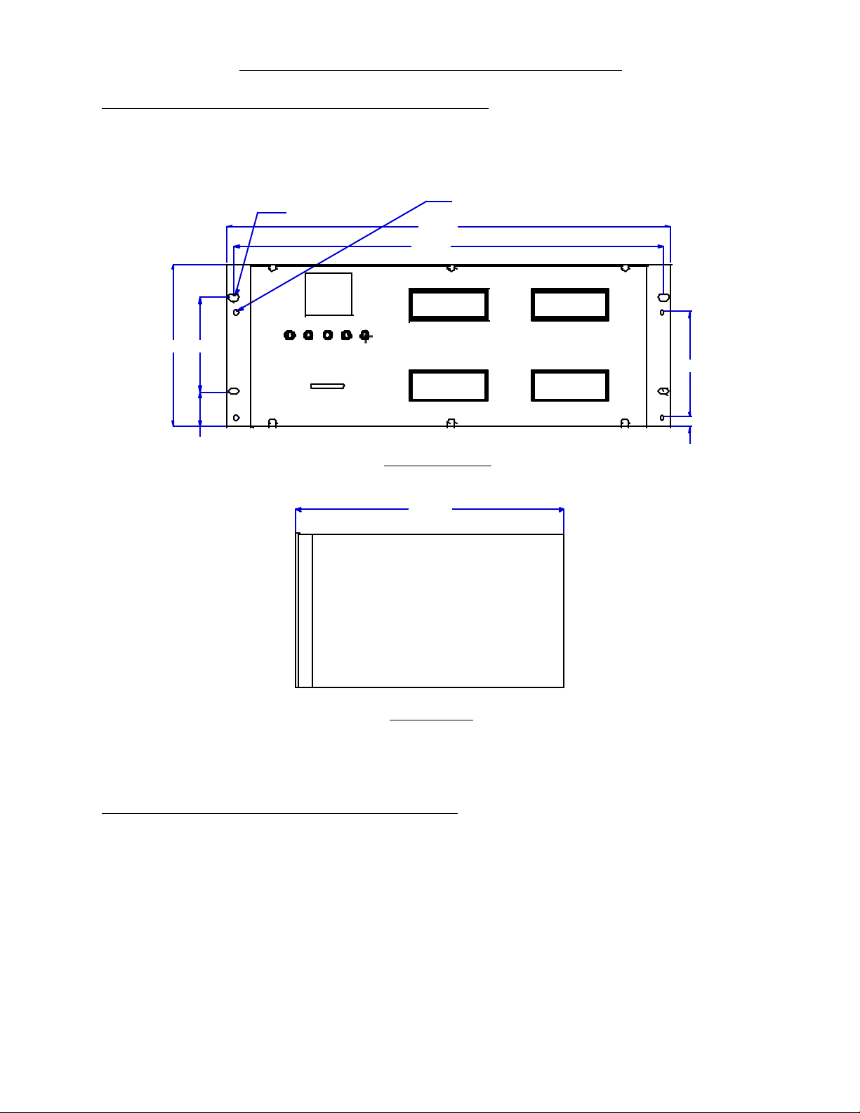
Mounting the Pioneer-16R Gas Monitor
The subrack which houses the monitor is suitable for mounting in a 19” rack or rack enclosure. Position
the subrack in the rack as desired and use the mounting flange on each side of the subrack to mount it to
the rack with screws. .28” diameter slotted holes are provided on the flanges for mounting. Two .20”
diameter holes are also provided on the mounting flanges for mounting of a handles if desired.
Ø.20,4
Ø.28,4
X
18.94
18.31
3.986.9
X
4.49
1.48
PIONEER-16
16 POINTGAS
R
MONIT
OR
.
37
Front View
11.941
Side View
Figure 2-1: Outline & Mounting
Wiring the Pioneer-16R Gas Monitor
All external and detector wiring terminals are accessible at the back of the subrack. See the wiring diagram
below for external wiring connections.
Pioneer-R16 Operator’s Manual Installation & Startup 5
Page 7

Connecting External Alarms
Perform the following procedure to connect external alarms to the Pioneer.
NOTE: The analyzer card includes external alarm connections that are dedicated to the applicable
channel only.
1. Guide the wiring of the external alarm to the rear of the subrack.
CAUTION: If the external alarm device is powered by AC current, do not route the external alarm
wiring and detector wiring through the same conduit hub or cable. The external alarm wiring may
disrupt the transmission of the detector signal to the Pioneer.
Pioneer-R16 Operator’s Manual Installation & Startup 6
Page 8
2. Connect the leads from the external alarm to the terminals on the appropriate external wiring
NO
COM
terminal strip.
NC
Figure 2-3: External Alarm Wiring
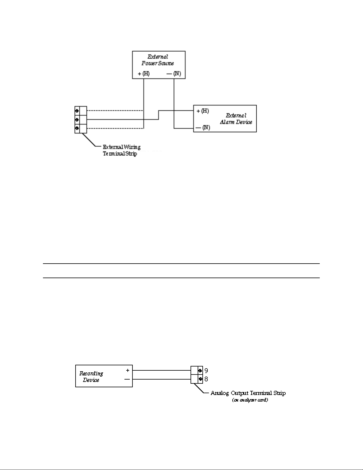
Connecting Recorders
Perform the following procedure to connect a recording device to the Pioneer. The output at the analyzer
card’s analog output terminal strip is a 4 to 20 mA or 0 to 1 V signal that is proportional to the detection
range of the applicable detector. Unless specified, the analyzer card is set up at the factory for 4 to 20 mA
output.
1. Gain access to the rear of the monitor and locate the analog output terminal strip on the applicable
analyzer card. (The analog output terminal strip is the 2-point terminal strip between the detector
terminal strip and the external alarm terminal strip.)
2. Route the wiring from the recording device to the rear of the monitor.
CAUTION: Do not route power and detector wiring through the same conduit hub or cable. The power
wiring may disrupt the transmission of the detector signal to the monitor.
3. Connect the leads from the recording device to the analog output terminal strip as shown in Figure 2-
4.
Figure 2-4: Recorder Output Wiring
Pioneer-R16 Operator’s Manual Installation & Startup 7
Page 9

Connecting RKI Detectors
See the applicable detection insert for wiring the detector(s) supplied by RKI Instruments, Inc. To the
Pioneer-R16.
Connecting User-Supplied 4 to 20 mA Transmitters
NOTE:See Generic 4 - 20 mA Transmitter Insert for more detailed information related to the use of user-
supplied 4 to 20 mA transmitters with the Pioneer-R16.
Perform the following procedure to connect a 4 to 20 mA transmitter (that you supply) to the Pioneer:
1. At the rear of the subrack locate the detector terminal strip on the applicable analyzer card. (The
detector terminal strip is the 7-point terminal strip that is below the analog output terminal strip.)
2. Route the cable leading from the transmitter to the rear of the subrack.
CAUTION: Do not route power and transmitter wiring through the same conduit hub. The power wiring
may disrupt the transmission of the transmitter’s signal to the Pioneer.
3. Connect the wires to the detector terminal strip of the applicable analyzer card as shown in Figure 2-5
below. The detector is the 7-point terminal strip (terminals 1 through 7) on the card.
Figure 2-5: Generic 4 to 20 mA Transmitter Output Wiring
Starting up the Pioneer-16R Gas Monitor
Perform the following procedures to place the Pioneer-16R into normal operation.
1. Complete the mounting and wiring procedures described earlier in this chapter.
2. Complete all installation procedures described in the gas detection insert(s).
3. Verify that all wiring connections are correct and secure.
4. Plug in or turn on the incoming power source (AC or DC) at the power source end.
NOTE:To prevent unwanted alarms during warm up, the alarm circuits are not active for 20 seconds to 2
minutes (depending on warm up) from the time you turn the power switch on.
5. Verify the following:
- The PILOT light on the front panel is on
- The POWER light on the main circuit board is on.
- The pilot light on each analyzer card is flashing.
If the pilot lights are not on or flashing, see the troubleshooting guide.
Pioneer-R16 Operator’s Manual Installation & Startup 8
Page 10

6. Perform the start-up procedure for each detector as described in the gas detection insert(s).
Pioneer-R16 Operator’s Manual Installation & Startup 9
Page 11

Chapter 3: Operation
Normal Operation
Normal operation is defined as follows:
• The start-up procedure is complete.
• The Pioneer is not indicating an alarm 1, alarm 2, alarm 3, or fail condition.
• The Pioneer is not running the Instrument Setup, Channel Setup, Calibrate, or Display Setpoints and
Readings program.
During normal operation, the Pioneer simultaneously displays the target gas, unit of measure, and current
gas reading for all active channels. The Pioneer displays the readings horizontally for each channel. Four
channels are displayed on each of the four displays visible through the front panel. On each display the
channel sequence starts at the top and goes down. For example, on the upper left display, channel 1 is
the top reading and channel 4 is the bottom reading.
The PILOT light on the front panel, the POWER light on the main circuit board, and the pilot light on each
analyzer card are on during normal operation indicating that the monitor and analyzer cards are receiving
incoming power. The output at terminals 8 and 9 of the analyzer card’s output terminal strip is 4 to 20 mA or
0 to 1 V and is proportional to the detection range of the detector that is wired to the analyzer card. (The
standard output at terminals 8 and 9 is 4 to 20 mA.)
Alarm Indications
This section describes the Pioneer in alarm 1, alarm 2, alarm 3, and fail conditions and suggests response
to these conditions. Table 3-1 lists the alarm indications for each condition.
NOTE:The Pioneer includes alarm on and alarm off delay settings. The alarm indications described in this
section operate according to the default delay settings. See the Channel Setup program section
in the applicable detection insert to display or change the alarm on and alarm off delay settings.
TABLE 3-1: Visual and Audible Alarm Indications
Condition Cause Visual Indication Audible
Indication
Alarm 1 Increasing (or decreasing for O2) gas
reading at or above alarm 1 setpoint
Alarm 2 Increasing (or decreasing for O2) gas
reading at or above alarm 2 setpoint
Alarm 3 Increasing gas reading at or above
alarm 3 setpoint
Fail • Disconnected or misconnected
detector wiring
• Disconnected or misconnected
analyzer card
• Display reading below fail setpoint
• Defective components
* The ALARM 1 and ALARM 2 lights are not on for oxygen channels
NOTE:You can select normally energized or normally de-energized relays in the Channel Setup program.
The following sections describe the default setting for the relays: normally de-energized. The fail
• ALARM 1 light is on
• Gas reading flashes
• ALARM 1 and ALARM 2
lights are on
• Gas reading flashes
• ALARM 1, ALARM 2 and
ALARM 3 lights are on*
• Gas reading flashes
• Fail light is on Steady tone
Pulsing tone
Faster pulsing
tone than Alarm 1
Faster pulsing
tone than Alarm 2
Pioneer-R16 Operator’s Manual Operation 10
Page 12

relay is factory-set for normally energized and is not user-selectable.
Alarm 1 Condition
This section describes the audible and visual indications for an alarm 1 condition and suggests response
to an alarm 1 condition.
• Alarm 1 condition indications
When the gas reading of an active channel reaches the alarm 1 setpoint, the Pioneer senses an alarm
1 condition. The Pioneer alerts you to an alarm 1 condition as follows:
- The ALARM 1 light turns on
- The gas reading in alarm 1 condition flashes
- The buzzer sounds a pulsing tone
- The common alarm 1 relay energizes
- The alarm 1 relay on the applicable analyzer card energizes
• Responding to an alarm 1 condition
- Follow your established procedure for a low level combustible or toxic gas condition or a
decreasing oxygen content condition.
- After the gas reading falls below the alarm 1 setpoint, press the reset switch to reset the alarm 1
circuit. Resetting the alarm 1 circuit silences the buzzer, turns off the ALARM 1 light, and deenergizes the common and analyzer card alarm 1 relays.
NOTE:To silence the buzzer while in an alarm 1 condition, press the reset switch. You cannot de-
energize the alarm 1 relays until the gas reading falls below (above for oxygen) the alarm 1
setpoint.
Alarm 2 Condition
This section describes the audible and visual indications for an alarm 2 condition and suggests response
to an alarm 2 condition.
• Alarm 2 condition indications
When the gas reading of an active channel reaches the alarm 2 setpoint, the Pioneer senses an alarm
2 condition. The Pioneer alerts you to an alarm 2 condition as follows:
- The ALARM 2 light turns on
- The gas reading in alarm 2 condition continues to flash
- The buzzer sounds a faster pulsing tone than an alarm 1 condition
- The common alarm 2 relay energizes
- The alarm 2 relay on the applicable analyzer card energizes
• Responding to an alarm 2 condition
This section suggests response to an alarm 2 condition.
- Follow your established procedure for a mid level combustible or toxic gas condition or a severe
decreasing oxygen content condition.
- After the gas reading falls below the alarm 2 setpoint, press the reset switch to reset the alarm
circuit. Resetting the alarm circuit turns off the ALARM 2 light, and de-energizes the common and
analyzer card alarm 2 relays.
NOTE:To silence the buzzer while in an alarm 2 condition, press the reset switch. You cannot de-
energize the alarm 2 relays until the gas reading falls below (above for oxygen) the alarm 2
setpoint.
Alarm 3 Condition
This section describes the audible and visual indications for an alarm 3 condition and suggests response
to an alarm 3 condition.
• Alarm 3 condition indications
Pioneer-R16 Operator’s Manual Operation 11
Page 13

When the gas reading of an active channel reaches the alarm 3 setpoint, the Pioneer senses an alarm
3 condition. The Pioneer alerts you to an alarm 3 condition as follows:
- The ALARM 3 light turns on
- The gas reading in alarm 3 condition continues to flash (the gas reading for O2 channels begins
flashing) and the buzzer sounds a faster pulsing tone than an alarm 1 or alarm 2 condition
- The common alarm 3 relay energizes
- The alarm 3 relay on the applicable analyzer card energizes
NOTE:The alarm 3 relay does not energize if you elect to use it as the channel’s fail relay in the
Channel Setup program (see the “Channel Setup Program” section of the applicable
detection insert ).
• Responding to an alarm 3 condition
This section suggests response to an alarm 3 condition.
- Follow your established procedure for a high level combustible or toxic gas condition or an
increasing oxygen content condition.
- After the gas reading falls below the alarm 3 setpoint, press the reset switch to reset the alarm 3
circuit. Resetting the alarm 3 circuit turns off the ALARM 3 light, and de-energizes the common
and analyzer card alarm 3 relays.
NOTE:To silence the buzzer while in an alarm 3 condition, press the reset switch. You cannot de-
energize the alarm 3 relays until the gas reading falls below the alarm 3 setpoint.
Fail Condition
This section describes the audible and visual indications for a fail condition and suggests response to a fail
condition.
• Fail condition indications
The Pioneer senses a fail condition for any of the following:
- The detector wiring is disconnected or incorrectly connected.
- The analyzer card is disconnected or incorrectly connected.
- The display reading is below the fail setpoint.
- The monitor or detector is malfunctioning.
When the Pioneer senses a fail condition, it alerts you as follows:
- The FAIL light turns on.
- The gas reading in fail condition flashes
- The buzzer sounds a steady tone
- The common fail relay de-energizes
NOTE:If you elected to use the analyzer card’s alarm 3 relay as an individual fail relay in the Channel
Setup program, the relay de-energizes in a fail condition (see the “Channel Setup Program”
section of the applicable detection insert).
• Responding to a fail condition
This section suggests response to a fail condition.
1. Verify that the detector wiring is correctly and securely connected.
2. Verify that the analyzer card is securely and correctly installed. (The components of the analyzer
card face left when the analyzer card is correctly installed.)
3. See the troubleshooting guide in the applicable detection insert.
Instrument Setup Program
This section describes the Instrument Setup program. You can display and change the following
instrument settings with the Instrument Setup program.
• Alarm On Delay
Pioneer-R16 Operator’s Manual Operation 12
Page 14

• Alarm Off Delay
• Relay Action
• Alarm Logic
• Alarm Silence
• Alarm Hysteresis
• Calibration Time Out
• Instrument ID (RS-232 or RS-485 address)
• Noise Filter
• Maximum Number of Channels (for use when connecting to other Pioneers)
• Zero Suppression
• Instrument Label
Navigating Through the Instrument Setup Program
Use the program buttons on the front panel to enter the program, move forward or backward through the
program, change settings within the program, and save or cancel changes to the program settings. Table
3-2 lists the function of each program button.
Table 3-2: Program Button Functions for the Instrument Setup Program
Button Function
ENTER • Moves you forward through the program
• Saves changes made to the program settings
• Enters the program (with the ESCAPE button)
UP/YES • Updates the setting that is flashing on the display screen
DOWN/NO • Updates the setting that is flashing on the display screen
ESCAPE • Moves you backward through the program
• Cancels changes made to the program
• Enters the program (with the ENTER button)
RESET • No function in this program
Running the Instrument Setup Program
This section describes how to enter the program, display and change program settings, and save or
cancel changes to the program settings.
• Entering the instrument setup program
1. Press the ENTER and ESCAPE buttons simultaneously three times. The upper left display
screen indicates that you are in the Instrument Setup program. All the screens of the Instument
Setup Program appear in the upper left display screen which displays channels 1 through 4
during normal operation.
2. Press the ENTER, UP/YES, or DOWN/NO button to continue. The program displays the Alarm
ON Delay screen.
• Alarm on delay screen
This screen indicates the length of time that the PioneerR-16 delays alarm indications (buzzer and
relays) when it senses an alarm 1, alarm 2, or alarm 3 condition. You can choose from a range of 0
Seconds to 60 Minutes. The default setting is 0 Minutes, 1 Seconds.
- To accept the alarm on delay setting and continue the program, press the ENTER button. The
program displays the Alarm OFF Delay screen.
- To update the alarm on delay setting:
1. Use the UP/YES and DOWN/NO buttons to display the setting you want.
Pioneer-R16 Operator’s Manual Operation 13
Page 15

2. Press the ENTER button to continue the program. The program displays the Alarm OFF Delay
screen.
• Alarm Off Delay Screen
This screen indicates the length of time that the Pioneer-R16 delays turning off alarm indications
(buzzer and relays) after an alarm 1, alarm 2, or alarm 3 condition passes. You can choose from a range
of 0 Seconds to 60 Minutes. The default setting is 0 Minutes, 0 Seconds.
- To accept the alarm off delay setting and continue the program, press the ENTER button. The
program displays the Relay Action screen.
- To update the alarm off delay setting:
1. Use the UP/YES and DOWN/NO buttons to display the setting you want.
2. Press the ENTER button to continue the program. The program displays the Relay Action
screen.
• Relay Action Screen
This screen indicates how the relays operate in normal and alarm conditions. If the setting is
NORMALLY DE-ENERGIZED, the relays energize in alarm conditions. If the setting is
NORMALLY ENERGIZED, the relays de-energize in alarm conditions. The default setting is
NORMALLY DE-ENERGIZED.
NOTE: The common fail relay and channel fail relay (if assigned) are not affected by this setting. Fail
relay(s) are factory-set as normally energized and are not adjustable.
- To accept the relay action setting and continue the program, press the ENTER button. The
program displays the Alarm Logic screen.
- To update the relay action setting:
1. Use the UP/YES or DOWN/NO button to display the setting you want.
2. Press the ENTER button to continue the program. The program displays the Alarm Logic
screen.
• Alarm Logic Screen
This screen indicates how an alarm circuit is reset after the applicable alarm condition passes. If the
setting is LATCHING, you must press the reset switch after the alarm condition passes to reset the
alarm circuit. If the setting is AUTO-RESET, the alarm circuit is automatically reset after the alarm
condition passes. The default setting is LATCHING.
Pioneer-R16 Operator’s Manual Operation 14
Page 16

- To accept the alarm logic setting and continue the program, press the ENTER button. The
program displays the Alarm Silence screen.
- To update the alarm logic setting:
1. Use the UP/YES or DOWN/NO button to display the setting you want.
2. Press the ENTER button to continue the program. The program displays the Alarm Silence
screen.
• Alarm Silence Screen
This screen indicates how the buzzer operates during alarm conditions. If the setting is ON, you can
use the reset switch to silence the buzzer during alarm conditions. If the setting is OFF, you cannot
silence the buzzer until all alarm conditions pass. The default setting is ON.
- To accept the alarm silence setting and continue the program, press the ENTER button. The
program displays the Alarm Hysteresis screen.
- To update the alarm silence setting:
1. Use the UP/YES or DOWN/NO button to display the setting you want.
2. Press the ENTER button to continue the program. The program displays the Alarm
Hysteresis screen.
• Alarm Hysteresis Screen
This screen indicates when the PioneerR-16 considers an alarm condition passed. The alarm
hysteresis feature helps prevent readings that are near an alarm setpoint from frequently going into
and out of alarm (relay chattering). For example, if the alarm hysteresis setting is 2.0% of fullscale,
fullscale is 10.0 ppm, and the alarm 1 setpoint is 3.0 ppm; then the Pioneer will not consider the alarm
1 condition “passed” until the reading goes below 2.8 ppm. You can choose from a range of 0.0% to
10.0% of fullscale (in 0.1% increments). The default setting is 2.0%.
- To accept the alarm hysteresis setting and continue the program, press the ENTER button. The
program displays the Calibration Time Out screen.
- To update the alarm hysteresis setting:
1. Use the UP/YES or DOWN/NO button to display the setting you want.
2. Press the ENTER button to continue the program. The program displays the Calibration Time
Out screen.
• Calibration Time Out Screen
The Pioneer-R16’s Calibrate program includes two separate time-out features. The first time-out
feature is a general 5-minute time-out. The Pioneer automatically returns to the normal screen if you
do not move from one Calibrate screen to another within 5 minutes. You cannot adjust this setting,
and it affects all Calibrate screens except the Fresh Air and Calibration screens.
Pioneer-R16 Operator’s Manual Operation 15
Page 17

The second time-out feature affects the Fresh Air and Calibration screens only. These are the screens
you use during calibration to adjust the zero and span readings (either at the transmitter or the
Pioneer). The Pioneer automatically returns to the normal screen if you do not move from the Fresh
Air or Calibration screen within the time-out setting specified in the screen below. You can choose
from a range of 10 to 100 minutes (in increments of 10). The default setting is 10 Minutes.
- To accept the calibration time out setting and continue the program, press the ENTER button.
The program displays the Instrument ID screen.
- To update the calibration time out setting:
1. Use the UP/YES or DOWN/NO button to display the setting you want.
2. Press the ENTER button to continue the program. The program displays the Instrument ID
screen.
• Instrument ID screen
This screen indicates the ID number (address) for this Pioneer-R16. The instrument ID is recorded in
the datalog when the datalog records instrument readings. You can choose from a range of 1 to 255.
The default setting is 1.
- To accept the instrument ID setting and continue the program, press the ENTER button. The
program displays the Noise Filter screen.
- To update the instrument ID setting:
1. Use the UP/YES or DOWN/NO button to display the setting you want.
2. Press the ENTER button to continue the program. The program displays the Noise Filter
screen.
• Noise filter screen
This screen indicates the length of time that the Pioneer-R16 averages data. You can choose from a
range of 0.5 to 15.0 seconds (in increments of 0.5). The default setting is 2.5 Seconds.
NOTE: The Pioneer-R16 continuously displays gas readings although it averages gas readings
according to the noise filter setting.
Pioneer-R16 Operator’s Manual Operation 16
Page 18

- To accept the noise filter setting and continue the program, press the ENTER button. The
program displays the Number of Channels screen.
- To update the noise filter setting:
1. Use the UP/YES or DOWN/NO button to display the setting you want.
2. Press the ENTER button to continue the program. The program displays the Number of
Channels screen.
• Number of channels screen
This screen indicates the maximum number of channels possible for the Pioneer-R16. The maximum
number of channels possible is 16 (for a fully loaded subrack with four displays). This is factory set for
16 channels and if less than 16 are loaded, they unused channels may be deactivated in the Channel
Setup Program.
16
- To accept the number of channels setting and continue the program, press the ENTER button.
The program displays the Zero Suppression screen.
- To update the number of channels setting:
1. Use the UP/YES or DOWN/NO button to display the setting you want.
2. Press the ENTER button to continue the program. The program displays the Zero
Suppression screen.
• Zero suppression screen
This screen indicates the zero suppression for the Pioneer-R16. The zero suppression feature helps
prevent “jumpy” readings near the normal reading. For example, if the zero suppression setting is
2.0% of fullscale and fullscale is 10.0 ppm, then the Pioneer will display a reading of 0.0 ppm for gas
readings from -0.2 to 0.2 ppm. You can choose from a range of 0.0% to 5.0% (in 0.1% increments).
The default setting is 2.0%.
- To accept the zero suppression setting and continue the program, press the ENTER button. The
program displays the Instrument Label screen.
- To update the zero suppression setting:
1. Use the UP/YES or DOWN/NO button to display the setting you want.
2. Press the ENTER button to continue the program. The program displays the Instrument
Label screen.
• Instrument label screen
This screen indicates the identifying label for this Pioneer-R16. You can choose a label of up to 15
characters. Characters can be letters, numbers, symbols, or blank spaces. The default setting is RKI
INSTRUMENTS.
Pioneer-R16 Operator’s Manual Operation 17
Page 19

- To accept the instrument label setting and continue the program, press the ENTER button until
the Instrument Setup Exit screen displays.
- To update the instrument label setting:
1. Use the ENTER button to select the character you want to change. (The character flashes
when it is selected.)
2. Press the UP/YES or DOWN/NO button to display the character you want, then press the
ENTER button to select the next character.
3. Repeat steps 1 and 2 until the label is correct, then press the ENTER button until the
Instrument Setup Exit screen displays.
• Instrument setup exit screen
This screen saves or cancels any changes you made in the Instrument Setup program.
- To save changes and exit the program, press the ENTER button. A confirmation message
displays, then the normal screen displays. The Pioneer is in normal operation.
- To cancel changes and exit the program, press the ESCAPE button until the following message
displays: “INSTRUMENT SET-UP NOT SAVED. USING PREVIOUS VALUES.” Then the normal
screen displays and the Pioneer is in normal operation.
Display Setpoints and Readings Program
This section describes the Display Setpoints and Readings program. You can display the following in this
program. (You can also allow the Pioneer to perform a self check procedure and reset the minimum and
maximum readings in this program.)
• Software versions
• Time Weighted Average (TWA) and Short Term Exposure Limit (STEL) readings (for applicable
channels)
• Minimum and maximum readings (for each channel)
• Alarm Sets (for each channel)
Navigating Through the Display Setpoints and Readings Program
Use the reset switch to begin the program, display the setpoints and readings, and exit the program.
NOTE: This is a display only program. You cannot change settings or gas readings in the Display
Setpoints and Readings program.
Running the Display Setpoints and Readings Program
This section describes how to display the various setpoints and gas readings that are included in this
program. This section also describes how to display the time and date and begin the self check
procedure.
NOTE: Once you display one of the screens, the Pioneer automatically returns to the normal screen in
1 minute if you do not continue or exit the program.
• To display software versions:
The Display Setpoints and Readings program displays the version number of the Pioneer’s
Pioneer-R16 Operator’s Manual Operation 18
Page 20

instrument, display, and channel software programs.
1. Press and hold down the reset switch to enter the program.
2. When the DISPLAY VERSIONS screen appears, release the reset switch.
3. Press and release the reset switch to display the remaining software versions and return to the
normal screen.
• To display TWA and STEL readings:
The Pioneer continuously computes Time Weighted Average (TWA) and Short Term Exposure Limit
(STEL) readings for all active channels.
NOTE: The Pioneer does not calculate or display TWA and STEL setting for oxygen channels or
combustible gas channels that have a unit of measure setting of %LEL. However, the Pioneer does
calculate and display TWA and STEL settings for combustible gas channels that have a unit of
measure setting of PPM/LEL.
The STEL reading represents a channel’s average gas readings for the past 15 minutes.
The TWA reading represents a channel’s average gas readings for the past 8 hours.
1. Press and hold down the reset switch to enter the program.
2. When the DISPLAY TWA/STEL screen appears on the display screen, release the reset switch.
The STEL reading displays for the first active channel.
3. Press and release the reset switch to display the TWA reading for the first active channel.
4. Continue pressing and releasing the reset switch to display the STEL and TWA readings for the
remaining channels.
5. Press and release the reset switch to return to the normal screen.
• To display minimum and maximum readings:
The Pioneer stores the minimum and maximum reading for all active channels since the last time the
minimum and maximum readings were reset.
1. Press and hold down the reset switch to enter the program.
2. When the DISPLAY MIN/MAX screen appears on the display screen, release the reset switch.
The minimum reading displays for the first active channel.
3. Press and release the reset switch to display the maximum reading for the first active channel.
4. Continue pressing and releasing the reset switch to display the minimum and maximum readings
for the remaining channels.
5. Press and release the reset switch to return to the normal screen.
• To display alarm sets:
The Display Setpoints and Readings program displays the alarm sets for all active channels. The alarm
sets include the alarm logic, alarm silence, alarm setpoint, and alarm type settings.
NOTE: You can change the alarm logic and alarm silence settings in the Instrument Setup
program. You can change the alarm setpoint and alarm type settings in the Channel Setup
program.
1. Press and hold down the reset switch to enter the program.
2. When the ALARM SETS screen appears on the display screen, release the reset switch. The
alarm logic setting (LATCHING or AUTO-RESET) displays for all active channels.
3. Press and release the reset switch to display the alarm silence setting (ON or OFF) for all active
channels.
4. Continue pressing and releasing the reset switch to display the setpoint and alarm type for the fail,
alarm 1, alarm 2, and alarm 3 alarms of channel 1.
5. Repeat step 4 to display the setpoint and alarm type for the remaining active channels.
6. Press and release the reset switch to return to the normal screen.
• To perform the self check:
The Pioneer includes a self check feature that makes sure the analyzer card(s) and microprocessor are
operating correctly.
Pioneer-R16 Operator’s Manual Operation 19
Page 21

1. Press and hold down the reset switch to enter the program.
2. When the SELF CHECK screen appears on the display screen, release the reset switch. The
Pioneer performs the self check procedure and returns to the normal screen. This process takes
approximately 5 seconds.
• To reset Minimum/Maximum readings:
If you reset the minimum and maximum readings, you cannot retrieve the minimum and maximum
readings previously stored by the Pioneer.
1. Press and hold down the reset switch to enter the program.
2. When the RESET MIN/MAX screen appears on the display screen, release the reset switch.
3. The message “MIN/MAX RESET DONE” appears on the display screen, then the program returns
to the normal screen.
NOTE: See the detections insert(s) for a description of the Channel Setup Program.
Pioneer-R16 Operator’s Manual Operation 20
Page 22

Chapter 4: Maintenance
Preventive Maintenance
Preventive maintenance of the Pioneer-R16 consists of daily, monthly, and quarterly procedures to
ensure that the detectors remain on zero (20.9 for oxygen) in fresh air and are responsive to gas. The gas
detection inserts includes preventive maintenance schedules for the detectors supplied with your
Pioneer-R16.
Troubleshooting
The troubleshooting guide describes symptoms, probable causes, and recommended action for
problems you may encounter with the Pioneer.
NOTE:This troubleshooting guide describes controller problems only. See the Troubleshooting guide in
the applicable manual insert (Appendix B, Gas Detectors) for problems you may encounter with
the detectors.
No Power
• Symptoms
- All status lights are off.
- The display screen is blank.
• Probable causes
- The power wiring is disconnected or misconnected.
- The AC or DC fuse is blown.
• Recommended action
1. Verify that the wiring to the power source is correct and secure.
2. At the Pioneer-16R, verify that the wiring to the AC terminal strip is correct and secure.
3. Check the continuity of the applicable (AC or DC) fuse.
4. If the power difficulties continue, contact RKI Instruments, Inc., for further instruction.
Frequent or Suspect Alarms
• Symptoms
- The Pioneer-16R alerts you to frequent or suspect alarms, but the detector’s fresh air readings
remain on zero (20.9 for oxygen).
• Probable causes
- The Pioneer is experiencing false readings due to Radio Frequency Interference (RFI) or
Electromagnetic Interference (EMI).
- The detector wiring is disconnected, misconnected, or intermittent.
• Recommended action
1. Verify that the detector wiring is properly shielded (see the Installation section(s) in the applicable
detection insert).
2. Verify that the detector wiring is correct and secure.
3. Verify that power and detector wiring are not routed in the same conduit or cable.
4. Increase the alarm on delay setting in the Instrument Setup program (see Chapter 3, Operation).
5. If the frequent or suspect alarm difficulties continue, contact RKI Instruments, Inc., for further
instruction.
Jumpy Readings
• Symptoms
- The display readings often momentarily increase or decrease.
Pioneer-R16 Operator’s Manual Maintenance 21
Page 23

• Probable causes
- The Pioneer is experiencing false readings due to Radio Frequency Interference (RFI) or
Electromagnetic Interference (EMI).
- The noise filter setting is too low.
- The zero suppression setting is too low.
• Recommended action
1. Verify that the detector wiring is properly shielded (see the Installation section(s) in the applicable
detection insert).
2. Verify that the detector wiring is correct and secure.
3. Verify that power and detector wiring are not routed in the same conduit or cable.
4. Increase the noise filter setting in the Instrument Setup program (see Chapter 3, Operation).
5. Increase the zero suppression setting in the Instrument Setup program (see Chapter 3,
Operation).
6. If the display difficulties continue, contact RKI Instruments, Inc., for further instruction.
Replacing Components
This section describes procedures to replace the analyzer card and fuses. To replace other components
of the Pioneer, contact RKI Instruments, Inc., for further information.
Replacing the Analyzer Card
CAUTION: Removing or plugging in an analyzer card with the power
on may damage the analyzer card or the Pioneer-R16’s
main circuit board.
1. Turn off or unplug all incoming power to the Pioneer at the power source end.
2. Gain access to the rear of the monitor.
3. Gently pull the old card out of its socket and slide it out of its card guide.
4. Plug the replacement analyzer card into the guide.
NOTE: The components of the analyzer card face left when the card is installed correctly.
5. Plug in or turn on all incoming power to the monitor at the power source end., then verify that the
pilot light on the replacement analyzer card is flashing.
CAUTION: If installing a new channel, define the channel
position as Oxygen and activate (see detection
insert) before turning power off to plug in new
module.
Replacing the AC Fuse
1. Turn off or unplug all incoming power to the monitor at the power source end.
2. Gain access to the rear of the monitor.
3. Gently pull the Power I/O card toward you and slide it out of its plastic card guides.
4. Remove the AC fuse(s) from its holder. The AC fuse(s) is behind the AC terminal strip and to the
right of the relays.
NOTE: If the monitor is configured for 115 VAC operation, only one fuse is used, F1. If it is
configured for 220 VAC, both F1 and F2 are used.
CAUTION: Verify that the replacement fuse is the same type and rating as the fuse you are
replacing.
Pioneer-R16 Operator’s Manual Maintenance 22
Page 24

5. Install the appropriate replacement fuse in the fuse holder.
6. Align the Power I/O card in its card guide with the fuses on the right and the terminal blocks on the
top side of the card.
7. Gently push the Power I/O card into its socket on the main circuit board.
8. Plug in or turn on all incoming power to the monitor at the power source end.
Replacing the DC Fuse
1. Turn off or unplug all incoming power to the monitor at the power source end.
2. Gain access to the rear of the monitor.
3. Gently pull the Power I/O card out of its main circuit board socket toward you and slide it out of its
plastic card guides.
4. Remove the DC fuse from its holder. The DC fuse is behind the RS 232 terminals and to the left
of the relays.
CAUTION: Verify that the replacement fuse is the same type and rating as the fuse you are
replacing.
5. Install the appropriate replacement fuse in the fuse holder.
6. Align the Power I/O card in its card guide with the fuses on the right and the terminal blocks on the
top side of the card.
7. Gently push the Power I/O card into its socket on the main circuit board.
8. Plug in or turn on all incoming power to the monitor at the power source end.
Appendix A: Parts List
This appendix lists the part numbers and descriptions for replacement parts and accessories offered for
the Pioneer-R16 Gas Monitor.
Table A-1: Parts List for the Pioneer Gas Monitor
Part No. Description
43-4165RK AC fuse, 115 VAC (3A 250V)
43-4177RK DC fuse, 12 VDC (8A 250V)
57-0004RK Analyzer card
57-0025RK Power I/O card
Pioneer-R16 Operator’s Manual Maintenance 23
 Loading...