

Page 1

INSTRUCTION MANUAL
MODEL GX-82A
PORTABLE THREE GAS DETECTOR
RKI Instruments, Inc.
33248 Central Ave. Union City CA 94587 • Tel: 510-441-5656
Page 2

Model GX-82A Instruction Manual
Table of Contents
INTRODUCTION 1
DESCRIPTION 2
COMPONENTS AND CONTROLS 3
Case 3
Control Panel 3
Switches 3
Battery Compartment 4
Interface Port 4
Buzzers and Earphone 5
Carrying Case 5
Sensors 5
Combustible Gas Sensor 5
Oxygen Sensor 6
CO, or H2S (toxic gas) Sensor 6
OPERATION 7
Preparation 7
Standard Start-up 7
Normal Operation 9
DISPLAY FUNCTIONS 10
User and Station ID 10
Peak 10
Average 11
Elapsed Time 11
Short-Term Exposure Limit (STL) 11
Time-Weighted Average (TWA) 12
Battery Voltage 12
Date / Time 12
Clear Data Logger 13
Log. Time 13
ALARMS 14
Alarm Indications 14
Resetting Alarms 15
Malfunction Alarm and Emergency Operation 16
Low Battery Alarm 17
CALIBRATION 18
Calibration Supplies and Equipment 18
Demand Zero and Calibration Preparation 18
Calibration Start-up 19
Auto Calibration 20
Combustibles Span 22
Oxygen Zero 23
H2S and CO Span 24
062796 RKI Instruments, Inc. Table of Contents
Page 3

Model GX-82A Instruction Manual
MAINTENANCE 25
Batteries 25
Sensor Maintenance 26
Combustibles Sensor 26
O2 Sensor 27
Toxics Sensors 27
Sensor Replacement 27
CO Filter 28
ACCESSORIES 29
Extender Cable 29
Sample-Drawing Pump 29
Manually-Operated Sample-Drawing Aspirator 30
USER OPTIONS 32
Entering Programming Mode 32
General Programming Hints 32
WARRANTY 37
Table of Contents Hayward, California (510) 441-5656
Page 4

Model GX-82A Instruction Manual
INTRODUCTION
The RKI Model GX-82A is an advanced gas detection instrument,
incorporating proven detection hardware and microprocessor controls.
The GX-82A is compact, convenient, and offers a full range of
features, including:
• Simultaneous detection of combustible gas, oxygen deficiency, and
carbon monoxide or hydrogen sulfide (detection for other toxic
gases is optional)
• Dot-matrix liquid crystal display (LCD) for complete, understandable information at a glance
• Distinctive audible alarms for dangerous conditions and malfunctions
• Intrinsic safety for Class I, Division I, Groups A, B, C, and D hazardous atmospheres
• Microprocessor control for reliability, ease of use, and advanced
capabilities, including data logging and user-adjustable alarms
• Convenient size, with the full range of well-known GX-82 accessories
WARNING
THE GX-82A IS DESIGNED TO DETECT COMBUSTIBLE
GAS
, OXYGEN DEFICIENCY, AND HYDROGEN SULFIDE OR
CARBON
MONOXIDE, WHICH CAN BE LETHAL. USERS
MUST
THIS
OF
062796 RKI Instruments, Inc. 1
FOLLOW THE INSTRUCTIONS AND WARNINGS IN
MANUAL TO ASSURE PROPER AND SAFE OPERATION
THE INSTRUMENT.
Page 5
Model GX-82A Instruction Manual
DESCRIPTION
The RKI Model GX-82A detects combustible gas (LEL), oxygen
deficiency (O2), and carbon monoxide (CO) or hydrogen sulfide
(H2S). See Table 1 for standard detection ranges for these gases. Gas
detection features include distinctive alarms for dangerous gas
concentrations, time-weighted averaging and short term exposure
limit for toxic gases, and logging of detection data.
Table 1: Standard Detection Ranges
Gas
Range
Detected
Combusti-
ble
O
2
0 - 100% LEL (lower
explosive limit)
0 - 40%
H2S 0 - 100 ppm (parts per mil-
lion)
CO 0 - 500 ppm
The GX-82A has a rugged plastic housing, touch-pad control panel,
and a back-lit dot matrix LCD. The included carrying case protects the
instrument and allows hands-free operation for the user.
The GX-82A is easy to adjust and maintain, with user-replaceable
batteries and sensors. The microprocessor control enables the user to
display a comprehensive listing of gas levels detected and other
related data.
2 Hayward, California (510) 441-5656
Page 6
Model GX-82A Instruction Manual
ol Panel
COMPONENTS AND CONTROLS
Case
The GX-82A has a durable plastic case. The sensors are housed in a
detachable block at the bottom of the instrument.
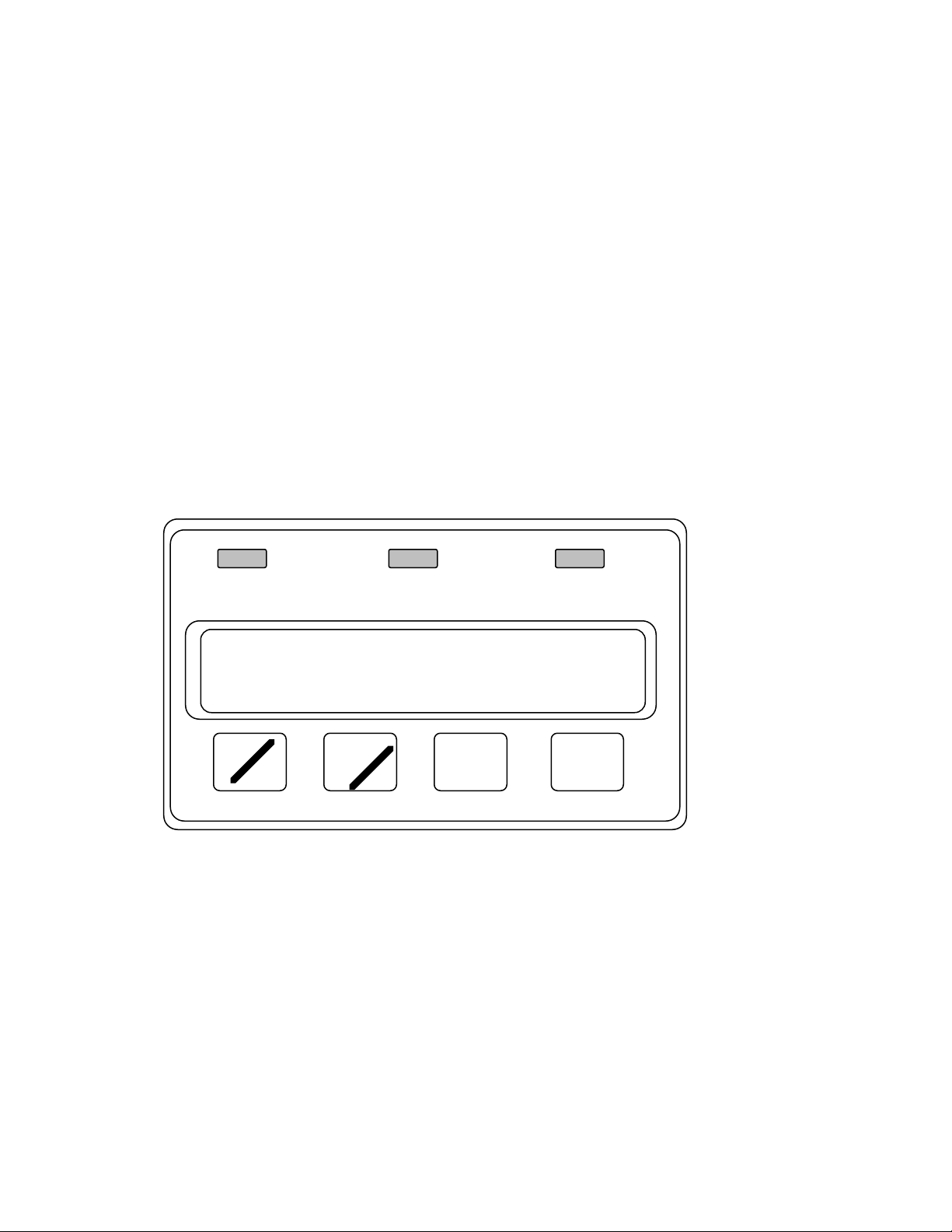
Control Panel
The control panel contains the display, alarm lights, and switches that
control the many functions of the GX-82A. The switches are touchpads, to reduce the possibility of accidental activation or damage. See
Figure 1.
% LEL %
AIR
▲
(SHIFT)
▼
DISPLAY
/(ADJ.)
PPM
ON/OFF
/ENTER
OFF - HOLD 5 SEC
Figure 1. Contr
Switches
1. ON/OFF/ENTER
The ON/OFF/ENTER switch controls power to the instrument.
(Bias power for the electrochemical sensors is not affected by the
power switch.) It also selects input modes to access userchangeable features.
062796 RKI Instruments, Inc. 3
Page 7

Model GX-82A Instruction Manual
2. AIR/▲
The AIR/▲ switch activates the GX-82A’s Demand Zero function,
which automatically adjusts the instrument in fresh-air conditions.
It is also used to scroll through the display and settings modes.
3. (SHIFT)/▼
The (SHIFT)/▼ switch scrolls through the display and settings
modes, and enters instructions into the GX-82A’s microprocessor.
4. DISPLAY/(ADJ)
The DISPLAY/(ADJ) switch activates the display modes, and
enters instructions into the GX-82A’s microprocessor.
5. Alarm LEDs
Three red light-emitting diodes (LEDs) provide visual alarms for
gas concentrations and malfunctions.
Battery Compartment
The GX-82A uses two “C” size cells; alkaline batteries will run the
GX-82A for approximately 10 hours, rechargeable nickel-cadmium
batteries will run for approximately 7 hours. (Rechargeable batteries
can be recharged in the GX-82A with the optional battery charger.)
The GX-82A battery compartment is located on the back of the
instrument. The battery cover has a strap to prevent accidental
opening.
Interface Port
The GX-82A’s built-in data logger records gas concentrations at
programmed intervals. These measurements can be downloaded
through the interface port to a PC-compatible computer for use in data
4 Hayward, California (510) 441-5656
Page 8

Model GX-82A Instruction Manual
analysis programs.
Buzzers and Earphone
An electronic buzzer is mounted at the back of the case, behind a felt
screen. The buzzer sounds for gas alarms and system malfunctions.
A 2.5 mm phone jack at the bottom left rear corner of the case
connects to an earphone, for use in high noise environments, and the
battery charger.
Carrying Case
The carrying case has openings for the diffusion grill, buzzer,
earphone/charger jack, control panel, and Data Logger interface port.
The carrying case includes a belt loop and shoulder straps.
Sensors
The sensors are mounted at the rear of the instrument, in a removable
block. A slotted metal cover protects the sensors, but allows
atmosphere to diffuse inward.
Combustible Gas Sensor
The LEL sensor detects combustible gas and vapors in the atmosphere
with a catalytic platinum element. The reaction of gas with oxygen on
the catalyst causes a change in the resistance of the element, which is
converted by the GX-82A into a reading of gas concentration.
062796 RKI Instruments, Inc. 5
Page 9

Model GX-82A Instruction Manual
Oxygen Sensor
The O2 sensor is an electrochemical cell, which reacts to the oxygen
in the atmosphere, producing a current proportional to the oxygen
concentration. This current is converted by the GX-82A into an
oxygen reading.
CO, or H2S (toxic gas) Sensor
The toxic gas sensor is an electrochemical cell, which reacts to gas in
the atmosphere, producing a current proportional to the concentration
of gas. The current is converted by the GX-82A into a measurement of
gas concentration. The CO sensor uses a charcoal filter disk that
covers its opening, to eliminate interference from H2S.
To maintain sensitivity and stability, these sensors are kept on a
continuous bias current, even when the instrument power is off.
Batteries with an adequate charge must be installed to provide the bias
current.
6 Hayward, California (510) 441-5656
Page 10

Model GX-82A Instruction Manual
OPERATION
Preparation
Normally the GX-82A requires little preparation before use. To install
the GX-82A Extender Cable, see the ACCESSORIES section.
Standard Start-up
1. Press the ON/OFF/ENTER switch once.
a.This message shows only when the “Lunchbreak” feature is
activated (See USER OPTIONS). Press the AIR/▲ switch to
continue Short Term Exposure Limit (STL) and Time-Weighted
Average readings from the last use of the GX-82A. Press DISP/
(ADJ.) to start new STL and TWA readings
STL TWA RESUME
YES:AIR NO:DISP
Lunchbreak can accumulate up to 100 hours of STL/TWA readings. If the 100-hour limit is exceeded, this prompt appears:
CANT RESUME
PUSH AIR: CLEAR
Press AIR/▲ to clear the memory and start accumulation of
readings.
b.The start-up battery check shows the minimum usable and
actual battery voltage (for example, 3.0V for fresh batteries).
BATTERY MIN. 2.3V
BATTERY NOW 3.0V
062796 RKI Instruments, Inc. 7
Page 11

Model GX-82A Instruction Manual
c.This message shows to verify that the data logger circuits are set
properly for accurate data collection according to date and time.
DATE / TIME
MMM DD YY 00:00
Note
The display illustrations in this manual show only “H2S.” If
your instrument detects CO or another toxic gas, information for that gas will appear in the H2S section of the display.
d.These messages show while the GX-82A checks itself for
proper operation. If a malfunction occurs, the display will alert
the user. (The display shows “HC” [hydrocarbons] for the
%LEL reading.)
SELF DIAGNOSIS
10 SECONDS TO GO
HC O2 H2S
STANDBY
d.The normal operating display shows after the “OK” message,
showing fresh-air concentrations for all gases. The GX-82A
sounds a double tone to indicate the instrument is in normal
8 Hayward, California (510) 441-5656
Page 12

operation.
Model GX-82A Instruction Manual
HC O2 H2S
OK
062796 RKI Instruments, Inc. 9
Page 13

Model GX-82A Instruction Manual
2. Verify Operation
To easily verify correct operation of the GX-82A, breathe out over
the diffusion grill of the instrument. The O2 reading should drop
measurably before returning to normal.
To verify detection of combustibles use a controlled source of
flammable vapor, for example, a bottle of isopropyl alcohol. The
audible alarm will sound, the %LEL will blink, and the HC will
flash on the display.
Caution
Do not use gas from a cigarette lighter to test response to
combustibles. Exposing the sensor to uncontrolled high
concentrations of gas in this manner will reduce
response and sensor life.
WARNING
IF THE GX-82A DOES NOT RESPOND TO THESE VERIFICA-
TIONS
MENT
DESCRIBED
THE
, TAKE IT TO A KNOWN “FRESH-AIR” ENVIRON-
, THEN FOLLOW THE DEMAND ZERO PROCEDURE
IN ADJUSTMENT AND CALIBRATION. REPEAT
VERIFY OPERATION PROCEDURE BEFORE USING THE
GX-82A IN A POTENTIALLY HAZARDOUS LOCATION.
Normal Operation
The GX-82A will continuously monitor the atmosphere, and display
the LEL, O2, and toxic gas concentrations present. If the GX-82A is
taken into a low-light environment, the display backlight will
automatically turn on. To use with sample-drawing attachments, insert
the probe into the area to be monitored and wait a few seconds for
10 Hayward, California (510) 441-5656
Page 14

response.
Model GX-82A Instruction Manual
062796 RKI Instruments, Inc. 11
Page 15

Model GX-82A Instruction Manual
DISPLAY FUNCTIONS
While the GX-82A is in normal operation, press the DISPLAY/(ADJ.)
switch to step through the measurement functions. The display will
hold for 20 seconds before reverting to normal detection, or until
DISPLAY/(ADJ.) is pressed to go to the next screen.
User and Station ID
This screen appears only when the user ID option is activated. (See
USER OPTIONS.) Use this screen to verify user, location, or other
programmed information.
U ID:0123456789
S ID:ABCDEFGHIJ
To change User and Station ID:
1. At the User and Station ID screen, press ON/OFF/ENTER.
2. The first character (left end) on “U ID” will flash. Press AIR or
SHIFT to scroll through 0 - 9, A - Z to select the desired character.
3. Press ON/OFF/ENTER to enter that value and move to the next
character.
4. Repeat steps 1. and 2. until the desired User and Station IDs are
entered.
Peak
The Peak function shows the highest (lowest for O2) concentrations
detected since the GX-82A was turned on. Peak readings (indicated
by “P” at the left side of the display) stay in the instrument’s memory
12 Hayward, California (510) 441-5656
Page 16

Model GX-82A Instruction Manual
until a higher level is detected, the data logger is cleared, or the unit is
turned off.
HC O2 H2S
P45 19.5 10.5
Average
The Average function shows the average gas concentrations (indicated
by “A” at the left side of the display) detected since the last time the
GX-82A was turned on or the data logger was cleared.
HC O2 H2S
A18 20.8 2.5
Elapsed Time
The Elapsed Time function shows the time in minutes since the
memory was cleared or the instrument was turned on. This allows the
user to easily track total time over multiple monitoring sessions.
TIME (OPERATION)
XXX MINUTES
Short-Term Exposure Limit (STL)
The STL function shows the average reading for toxic gases during
the last 15 minutes.
(STL) H2S
PPM XX.X
062796 RKI Instruments, Inc. 13
Page 17

Model GX-82A Instruction Manual
Time-Weighted Average (TWA)
The TWA function shows the average reading for toxic gases during
the last 8 hours. If 8 hours has not elapsed since the last time the
STEL/TWA was cleared, the average is still calculated over 8 hours,
with the missing time assigned a 0 value for readings.
(TWA) H2S
PPM XX.X
Battery Voltage
The Battery Voltage function shows the minimum operating voltage
and present battery voltage.
BATTERY MIN 2.3V
BATTERY NOW 3.0V
Note
The GX-82A automatically checks battery voltage during
start-up; if the measurement is below 2.3V, the GX-82A will
not operate.
Date / Time
This function shows the current time and date, for example:
DATE / TIME
JUL 8 95 14:23
14 Hayward, California (510) 441-5656
Page 18

Model GX-82A Instruction Manual
Clear Data Logger
The Clear Data Logger function allows the user to reset the data
logger storage to accept a new set of data. Clearing the Data Logger
also resets the Peak, Average, Time in Operation, STL, TWA, and
Log. Time readings. This function shows three displays. Press AIR/▲
to continue through this function, or DISPLAY/(ADJ.) to skip to the
next function.
CLEAR DATA LOG.
YES:AIR NO:DISP
ARE YOU SURE ?
YES:AIR NO:DISP
CLEARED
OK
Log. Time
The Log. Time function shows the time left on the data collection
program. The duration depends upon the frequency of sampling. Press
DISPLAY/(ADJ.) once more to return to the normal operating display.
LOG. TIME: XXX.0
HOURS REMAINING
062796 RKI Instruments, Inc. 15
Page 19

Model GX-82A Instruction Manual
ALARMS
Alarm Indications
1. Combustibles (%LEL)
If the combustible gas detected exceeds the first level alarm setting
(20% LEL for most applications), a pulsed tone will sound, the
%LEL LED will blink, and the “HC” on the display will flash.
If the combustible gas detected rises above the high alarm setting
(50% LEL for most applications), the alarm tone and LED will be
continuous. The LEL alarm may be turned off and on by the user;
see USER OPTIONS.
2. Oxygen
If the oxygen content of the air drops below the low alarm setting
(usually 19.5%), a pulsed tone will sound, the % LED will blink,
and the “O2” on the display will flash.
If the oxygen content of the air rises above the high alarm setting
(usually 23.5%), the alarm tone and LED will be continuous. The
O2 alarm may be turned off and on by the user; see USER
OPTIONS.
3. H2S or CO
If the H2S or CO detected exceeds the alarm setting, a pulsed tone
will sound, the PPM LED above the reading will blink, and “H2S”
or “CO” on the display will flash. The toxic gas alarm may be
turned off and on by the user; see USER OPTIONS.
16 Hayward, California (510) 441-5656
Page 20

Model GX-82A Instruction Manual
5. STEL (toxics only)
If the average toxic gas level detected over the last 15 minutes
exceeds the STL, an alarm will sound and the message “STL” will
show on the display in the field for that gas. The STEL alarm may
be turned off and on by the user; see USER OPTIONS.
6. TWA (toxics only)
If the average toxic gas level detected over the last 8 hours exceeds
the TWA, an alarm will sound and the message “TWA” will show
on the display in the field for that gas.
7. CLG (toxics only)
If toxic gas detected exceeds the ceiling level, the alarm tone and
LED will be continuous, and the display will alternate between
“CLG” and the name of that gas. The CLG alarm may be turned
off and on by the user; see USER OPTIONS.
8. If the full scale reading is exceeded for any channel, the alarm
tone and LED will be continuous. The display will show “MAX”
in the field for that gas.
Resetting Alarms
The GX-82A can be set for latching or self-resetting logic. Latching
alarms can not be reset until the gas concentration falls below the
alarm point. When the condition is corrected, press (SHIFT)/▼ to
reset the alarm. Self-resetting alarms will automatically shut off when
the concentration falls below the alarm point. (See USER OPTIONS.)
062796 RKI Instruments, Inc. 17
Page 21

Model GX-82A Instruction Manual
Malfunction Alarm and Emergency Operation
The GX-82A continuously monitors itself for proper operation. If a
malfunction occurs, a single steady “trouble” tone will sound, and one
of the following messages will show on the display:
1. Sensor failure
If any sensor fails during operation, the display will show the
failed sensor in parentheses (H2S sensor in this example):
SELF DIAGNOSIS
FAIL( H2S)
To continue using the GX-82A, turn it off, then follow the
appropriate start-up sequence. During start-up the display will
show the failed channel before the count down. In normal
operation display will indicate the failed sensor as “xx or xx.x.”
HC O2 H2S
0 20.9 XX.X
18 Hayward, California (510) 441-5656
Page 22

Model GX-82A Instruction Manual
Low Battery Alarm
When the battery charge drops near the lower limit, the display will
show the first screen below, with the “B” flashing. When the charge
drops to the limit, the second screen will show, with the “CHANGE
BATTERY” flashing, the buzzer will sound continuously, and the GX82A can not be used to monitor gas concentrations:
HC O2 H2S CO
B 0 20.9 00.0 0
HC O2 H2S CO
CHANGE BATTERY
062796 RKI Instruments, Inc. 19
Page 23

Model GX-82A Instruction Manual
CALIBRATION AND MAINTENANCE
The GX-82A’s microprocessor circuits provide advanced calibration
and adjustment features, including Demand Zero and Auto Calibration.
Note
Calibrate the GX-82A when a gas reading drifts below zero
or a sensor has been replaced.
Calibration Supplies and Equipment
For automatic one-source calibration, the RKI Four Gas Cylinder can
be used to adjust all sensors with one connection and one operation.
To calibrate the GX-82A with separate gas sources, you will need the
following supplies and equipment:
• Known calibrating samples of combustible and the appropriate
toxic gases. The samples should have concentrations in approximately the middle of the range of detection.
• An oxygen-free source, such as pure nitrogen or CO in a nitrogen
balance
• A flowmeter with a range of 0 - 1.0 SCFH
• A control valve/pressure regulator, non-absorbent tubing, and
adapter cups
Demand Zero and Calibration Preparation
1. Take the GX-82A to a non-hazardous location with fresh-air con-
ditions.
2. Turn on the instrument and allow 1 minute after the “OK” display
to warm up.
20 Hayward, California (510) 441-5656
Page 24

Model GX-82A Instruction Manual
3. Demand Zero
Press and hold the AIR/▲ switch on the control panel until a tone
sounds. Follow the instructions on the display:
DEMAND ZERO
HOLD AIR KEY
ADJUSTING ZERO
HOLD AIR KEY
ZERO ADJUSTED
RELEASE AIR KEY
The instrument will automatically set the LEL and toxic gas
circuits to zero and the O2 circuit to 20.9%.
Calibration Start-up
1. Preparation
Assemble the calibration cylinder (Four-Gas for Auto Calibration,
or a specific cylinder for separate gas calibration), valve/regulator,
flowmeter, and adapter cup.
Note
Allow adequate time for the GX-82A to respond to changes
in adjustment. Adjust the controls in small increments, then
wait approximately 3 seconds for a change in reading.
Ignore alarms during the calibration procedure.
062796 RKI Instruments, Inc. 21
Page 25

Model GX-82A Instruction Manual
2. Enter calibration mode
With the instrument on, press and hold the (SHIFT)/▼ switch,
then press the DISPLAY/(ADJ.) switch. The display will show:
1.AUTO CAL.
2.SET SPAN <HC>
The “1” will flash, indicating the active selection. To select Auto
Calibration, press ON/OFF/ENTER. (Go to next section, Auto
Calibration.)
To skip to separate calibration for individual sensors, press the
(SHIFT)/▼ switch to scroll down through the calibration menu
(Press AIR/▲ to scroll up). The flashing number indicates the
active selection. Press ON/OFF/ENTER to start calibration for
that selection. (Go to Combustibles Span section.)
Auto Calibration
At the Auto Calibration prompt, press AIR to enter the Auto
Calibration procedure, or DISPLAY to return to the calibration menu.
AUTO CALIBRATION
YES:AIR NO:DISP.
1. Setting Calibration Values
The Calibration Values display shows the current settings in the
instrument’s memory for Auto Calibration. These values must
agree with the gas concentrations written on the Four-Gas
22 Hayward, California (510) 441-5656
Page 26

Model GX-82A Instruction Manual
Cylinder.
AUTO CALIBRATION
50 12.0 25.0
To change the calibration values, press the (SHIFT)/▼ and
DISPLAY/(ADJ.). The following screen will appear.
SET CAL. <HC>
50 LEL
Press the AIR/▲ or (SHIFT)/▼ to adjust the LEL value to agree
with the concentration on the Four-Gas Cylinder. Press ON/OFF/
ENTER to advance to the SET CAL screen, the repeat the
adjustment procedure for O2, H2S and CO.
2. Perform Auto Calibration
After setting all Calibration Values, the display will return to the
Calibration Values screen.
a.Press ON/OFF/ENTER to go to the next screen:
GAS/WAIT/ENTER
0 20.9 0.0 0
b.Turn on the Four-Gas Cylinder and wait approximately 1 minute
for the flow and instrument readings to stabilize.
c.Press ON/OFF/ENTER to calibrate the detection circuits. The
062796 RKI Instruments, Inc. 23
Page 27

Model GX-82A Instruction Manual
END screen will appear:
AUTO CALIBRATION
NORMAL END
d.After the end screen, the display automatically returns to the
first calibration screen.
e Turn off the Four-Gas Cylinder and disconnect it from the valve.
f. Press (SHIFT)/▼ to scroll through the options to “7.RETURN,”
then press ON/OFF/ENTER to return to normal operation.
Combustibles Span
Note
The combustible gas sensor is a general hydrocarbon sensor
that responds to most flammable vapors and gases; the
response will vary depending upon the substance. For best
results, calibrate the instrument to the gas or vapor intended
to be detected. See Appendix A for Relative Response
Curves for common gases and vapors.
1. At the Calibration Mode screen, press (SHIFT)/▼ to scroll to “2.
SET SPAN <HC>.” Press ON/OFF/ENTER to select. The display
will show:
HC CAL. 0LEL
GAS/ADJ./ENTER
2. Turn on the combustible gas calibration source, for example a
50% LEL cylinder. Wait approximately 1 minute while the LEL
24 Hayward, California (510) 441-5656
Page 28

Model GX-82A Instruction Manual
reading stabilizes:
HC CAL. 45LEL
GAS/ADJ./ENTER
3. If the reading does not correspond to the sample, press the AIR/▲
switch to increase the reading, or the (SHIFT)/▼ switch to
decrease the reading.
4. Press ON/OFF/ENTER. The END screen will show:
HC CAL.
END
5. The display will automatically return to the Calibration Menu.
Press (SHIFT) to scroll down to the next desired calibration.
6. Turn off the combustible gas cylinder and disconnect it from the
valve.
Oxygen Zero
1. Connect an oxygen free or low-concentration (e.g. the RKI Four-
Gas Cylinder has 12% O2) known oxygen sample to the calibration adapter.
2. From the calibration menu, scroll to “3. SET O2 ZERO,” then
press ON/OFF/ENTER to start O2 zero. The display will show:
O2 CAL. 20.9%
GAS/ADJ./ENTER
3. Open the control valve to the sample source and set the flow to 1.0
SCFH.
062796 RKI Instruments, Inc. 25
Page 29

Model GX-82A Instruction Manual
4. The reading should fall to near zero for an oxygen-free sample, or
near the level of the low concentration sample. Adjust the reading
using the AIR/▲ or (SHIFT)/▼ switches.
5. Press ON/OFF/ENTER to complete the oxygen zero sequence.
6. Turn off the zero oxygen cylinder and disconnect it from the valve.
26 Hayward, California (510) 441-5656
Page 30

Model GX-82A Instruction Manual
H2S and CO Span
1. Connect a H2S or CO calibration cylinder to the adapter.
2. From the calibration menu, scroll to “4.SET SPAN <H2S>,” or
“5.SET SPAN <CO>.” Press ON/OFF/ENTER to start the selected
calibration.
3. Adjust the calibration value following the procedure in Combusti-
bles Span, steps 2 - 6.
Note
The GX-82A will display up to 99 ppm H2S, but the limit of
linear response is 60 ppm, well above acceptable exposure
levels.
The GX-82A will display up to 499 ppm CO, but the limit
of linear response is 150 ppm, well above acceptable exposure levels.
If any reading cannot be set to agree with the calibrating gas sample,
replace the sensor.
062796 RKI Instruments, Inc. 27
Page 31

Model GX-82A Instruction Manual
MAINTENANCE
Batteries
1. Check the battery voltage periodically by pressing the DISPLAY
switch to reach the Battery Voltage function. Replace the batteries
before the voltage drops to the operational limit (see OperationAlarms).
WARNING
TAKE THE GX-82A TO A NON-HAZARDOUS LOCATION
BEFORE
CHANGING OR CHARGING THE BATTERIES.
2. To replace the batteries, remove the battery compartment cover.
Remove the batteries and verify that the battery compartment and
electrical contacts are clean. Insert fresh batteries (alkaline or
fully-charged Ni-Cad) according to the polarity (+/-) markings
and replace the cover.
3. Recharging Batteries
Note
The GX-82A charger detects the installed battery type and
will not charge alkaline cells, to prevent damage to the
instrument. Only Ni-Cad cells will charge properly with the
GX-82A charger.
Rechargeable batteries may be recharged inside the GX-82A in a
non-hazardous location. Turn the instrument off, connect the
charger to the charger jack, and plug the charger into a 115 V AC
outlet. Full charge requires approximately 12 hours.
28 Hayward, California (510) 441-5656
Page 32

Model GX-82A Instruction Manual
3. Bias Current Discharge
The batteries continuously supply a small current to maintain the
toxics sensors, even when the instrument is off (see Sensor
Maintenance). This current drain is minimal, but will result in a
normal discharge of the batteries over a period of several weeks.
Note
If the batteries are fully discharged before replacement,
allow 1/2 hour for the toxic gas circuit to show a normal
response.
Sensor Maintenance
Electrochemical sensors (O2, H2S, CO) gradually deteriorate,
regardless of use, and require periodic replacement. Combustibles
sensor life is generally related to usage, but other factors may affect
duration.
The GX-82A sensors are easy to replace, but only the combustibles
sensor contains user-serviceable components. If a sensor requires
replacement, call RKI or your local distributor. All sensors are
warranted usable for one year from the date of shipment. Sensors that
fail within the warranty period will be replaced at no charge.
Combustibles Sensor
Replace the combustibles sensor or filaments when:
1. The combustibles circuit cannot be calibrated correctly.
2. The HC (%LEL) display does not show 0 immediately after the
start-up sequence, and it cannot be set to zero by the Demand Zero
command.
062796 RKI Instruments, Inc. 29
Page 33

Model GX-82A Instruction Manual
O2 Sensor
Replace the O2 sensor when:
1. The O2 circuit cannot be set to 00.0% on an oxygen-free sample.
2. The OXY (O2) display does not show 20.9% immediately after
the start-up sequence and after the Demand Zero command.
3. The O2 reading tends to drift with instrument orientation.
Toxics Sensors
Replace the sensor when:
1. The detection circuit cannot be calibrated correctly.
2. The display does not show 0 (CO) or 00 (H2S) immediately after
the start-up sequence and cannot be set to zero by Demand Zero.
Note
Allow up to 1/2 hour after the toxics sensors have been
replaced to show a normal response, then calibrate.
Sensor Replacement
1. Take the GX-82A to a non-hazardous location and turn the power
off.
2. Remove the instrument from the carrying case.
3. Press in the cover latch and slide the sensor cover down and away
from the instrument case.
30 Hayward, California (510) 441-5656
Page 34

Model GX-82A Instruction Manual
e 2. Sensor Installation
(CO only)
Block
4. To replace individual sensors, press down and turn counter-clock-
wise, then pull out of block. Figure 2 shows the installation of the
CO sensor with filter; do not use the filter with other sensors.
Sensor
CO Sensor
Filter (CO only)
Rubber Collar
Figur
5. Insert a new sensor and turn clockwise. Be sure to use the correct
socket for the sensor type; sensors are not interchangeable
between sockets.
6. Reinstall the cover.
7. Turn on the instrument and verify the display is normal.
8. Calibrate the detection circuit to work correctly with the new sen-
sor.
CO Filter
CO sensors are equipped with an activated carbon filter disk that
removes H2S and most hydrocarbons to limit interference with the CO
measurement.
Replace the filter when CO readings become suspect (e.g., CO circuit
calibrates properly, but shows response in a known CO-free
environment), or when replacing sensor, whichever comes first. See
Figure 2.
062796 RKI Instruments, Inc. 31
Page 35

Model GX-82A Instruction Manual
ACCESSORIES
Extender Cable
The Extender Cable extends the sensor block up to 10 meters from the
instrument, allowing confined space and remote monitoring, with all
the features of the GX-82A. The Extender cable includes the cable
with sensor block plug and socket, and a rubber guard for the sensor
cover.
1. Installing Extender Cable
Take the GX-82A to a non-hazardous area and turn off.
2. Remove the sensor cover.
3. Flip open the spring clips at the sides of the sensor block.
4. Pull the block straight up to unplug.
5. Plug the extender cable into the GX-82A, in place of the sensor
block. Flip closed the spring clips.
6. Plug the sensor block into the end of the Extender Cable. Close the
spring clips.
7. Slide the sensor cover over the block on the end of the Extender
Cable. Slip on the rubber guard.
8. Start-up the GX-82A and verify operation as normal.
Sample-Drawing Pump
The Sample-Drawing Pump accessory includes the pump, hose, and
probe. It provides continuous sample-drawn monitoring for a variety
of applications.
1. Turn off the GX-82A and take to a non-hazardous area.
2. Assemble the pump, probe, and hose. Remove the GX-82A’s
32 Hayward, California (510) 441-5656
Page 36

Model GX-82A Instruction Manual
sensor cover, then slide the pump into place. Make sure the pump
housing seats and clips securely.
2. Turn on the pump and the GX-82A and allow it to complete the
start-up procedure.
3. Take the instrument into the area to be monitored.
Caution
Do not place the probe tip in liquid or other materials
which could be drawn into the Pump or the GX-82A.
4. Place the probe tip in the desired location to sample the atmo-
sphere. Watch the GX-82A’s display for changes. If the sample
system becomes blocked, the low flow alarm will sound.
WARNING
WHEN THE SAMPLE-DRAWING PUMP IS ATTACHED, IT
MUST
CHANGES
RESPOND
AIR
SUREMENTS
RESUMING
BE RUNNING FOR THE GX-82A TO DETECT
IN GAS CONCENTRATIONS. THE GX-82A MAY
MORE SLOWLY TO CHANGES IN THE AMBIENT
. USE THE PUMP ONLY WHEN SAMPLE-DRAWING MEA-
ARE NECESSARY, AND REMOVE IT BEFORE
REGULAR MONITORING.
5. The Pump will run about 10 hours on a set of fresh “AA” batter-
ies. If the battery voltage drops too low, the low flow alarm will
sound. Take the GX-82A and Pump to a non-hazardous area
before replacing the batteries.
Manually-Operated Sample-Drawing Aspirator
The Sample-Drawing Aspirator accessory includes an adapter, hose,
aspirator bulb, and probe. It provides a low-cost solution to occasional
062796 RKI Instruments, Inc. 33
Page 37

Model GX-82A Instruction Manual
requirements for portable sample-drawn monitoring.
1. Assemble the probe, hose, bulb, and adapter. Slide the adapter
into place over the sensor cover.
2. Turn on the GX-82A and allow it to complete the start-up proce-
dure.
3. Take the instrument into the area to be monitored.
Caution
Do not place the probe tip in liquid or other materials
which could be drawn into the Aspirator accessory or
the GX-82A.
4. Place the probe tip in the desired location, then squeeze the aspi-
rator bulb several times, at a moderate pace. Watch the GX-82A’s
display for changes.
WARNING
WITH THE SAMPLE-DRAWING ASPIRATOR ATTACHED,
THE GX-82A DOES NOT MONITOR THE AMBIENT AIR. USE
THE
SUREMENTS
RESUMING
ASPIRATOR ONLY WHEN SAMPLE-DRAWING MEA-
ARE NECESSARY, AND REMOVE IT BEFORE
REGULAR MONITORING.
34 Hayward, California (510) 441-5656
Page 38

Model GX-82A Instruction Manual
USER OPTIONS
The advanced microprocessor program in the GX-82A allows the user
to select and adjust many of the detection and data logging features.
The GX-82A is pre-set to suit most applications; follow these
instructions only if required.
Entering Programming Mode
1. Take the GX-82A to a non-hazardous location—the instrument
does not detect gas during programming operations.
2. Turn the GX-82A off.
3. Hold down the AIR and (SHIFT) switches, then press ON. The
programming menu will appear:
1.SET NVRAM DEFAULT
2.SET COMBINATION GAS
General Programming Hints
• Press (SHIFT) to scroll down through the menu, and to change values in a specific option.
• Press AIR to scroll up through the menu, and to change values in a
specific option.
• Press ON/OFF/ENTER to select an individual option, and to enter
data during programming.
• The current option or value to be changed shows a flashing character
• Many options have on-screen instructions
062796 RKI Instruments, Inc. 35
Page 39

Model GX-82A Instruction Manual
SET DEF. NVRAM
1. “DEF. SET ALL”
The first option allows the user to reset all values for non-volatile
RAM; all options are returned to default values.
2. “DEF. SET ALARM”
The second option resets only the alarm levels to default values.
3. “DEF. SET O2 ZERO”
The third option resets the O2 zero to default value.
COMBINE GAS
Sets the display and circuitry for types of gases to be detected; there
are five possible combinations.
Note
Change the GAS COMBINATION values only when the
appropriate sensors are used in the corresponding sensor
sockets.
SET ALARM
Sets the alarm levels for gases detected by the GX-82A. If different
gases are specified by the GAS COMBINATION option, the Set
Alarm prompts will show those gases.
1. “SET ALARM <HC>”
Prompts the user to change LOW and HIGH %LEL alarms for
combustibles.
2. “SET ALARM <O2>”
Prompts changes for LOW and HIGH %O2 alarms.
36 Hayward, California (510) 441-5656
Page 40

Model GX-82A Instruction Manual
3. “SET ALARM <H2S> or <CO>”
Prompts changes for LOW, TWA, STL, and CLG (ceiling) alarms
for H2S or CO.
SET SERIAL No.
Sets the serial number for use by the Data Logger.
1. At the “SERIAL No.” screen, the first character (left end) will
flash. Press AIR or SHIFT to scroll through 0 - 9, A - Z to select
the desired character.
2. Press ON/OFF/ENTER to enter that value and move to the next
character.
3. Repeat steps 1. and 2. until the serial number is displayed, then
press ON/OFF/ENTER to go to the END screen.
SET DATE / TIME
Sets the date and time for use by the Data Logger.
1. The SET DATE / TIME screen shows the current settings, with the
month flashing.
2. Press AIR or (SHIFT) to select the desired month.
3. Press ON/OFF/ENTER to enter the selection and go to the next
setting.
4. Repeat steps 2 and 3 for each value: day, year, hours, minutes.
5. When the desire date/time is entered, press ON/OFF/ENTER to go
to the END.
SET INT. TIME
Sets the interval between logging events for the Data Logger.
Minimum value 10 seconds, maximum value 300 seconds.
062796 RKI Instruments, Inc. 37
Page 41

Model GX-82A Instruction Manual
LATCHING ALARM
Toggles the instrument alarm logic between self-resetting (default)
and latching alarms.
Note
In the event of an alarm, the latching alarms option requires
the user to press DISPLAY/(ADJ.) to reset the alarms, even
after the gas concentration has dropped below the alarm
level.
SET LUNCH
Toggles the Lunchbreak feature on and off. With Lunchbreak off
(default), the STL TWA RESUME screen does not show at start-up.
SET ID
Toggles the ID INPUT option on and off. With the option off (default)
the user can not change the USER and ID values (see Display
Functions).
SET TIME CAL.
Sets the interval between calibration alerts on the GX-82A. Default
setting is off, with a range of 1 - 9999 hours. Tip: hold AIR or
(SHIFT) to scroll rapidly through values.
SET LOG ALARM
Sets the value of Data Logger memory capacity alerts on the GX-82A.
Default setting is off, with a range of 1 - 100%. Tip: hold AIR or
(SHIFT) to scroll rapidly through values.
38 Hayward, California (510) 441-5656
Page 42

Model GX-82A Instruction Manual
AUTO CAL.
The procedure is the same as described in Calibration and
Maintenance, Auto Calibration.
DISPLAY VOL.
This feature is for factory use only.
START
Press ON/OFF/ENTER to begin the instrument’s normal start-up
sequence.
062796 RKI Instruments, Inc. 39
Page 43

Model GX-82A Instruction Manual
WARRANTY
RKI Instruments, Inc. warranties gas alarm equipment manufactured by Riken Keiki
Co., Ltd., and sold by us to be free from defects in materials and workmanship for a
period of one year from date of shipment from RKI Instruments, Inc. Any parts found
defective within that period will be repaired or replaced, at our option, free of charge.
This warranty does not apply to items that are subject to deterioration or consumption
in normal service, and which must be cleaned, repaired, or replaced routinely. Those
items include, but are not limited to:
Absorbent cartridges Sensors
Pump diaphragms and valves Filter elements
Lamp bulbs and fuses Batteries
This warranty is voided by mechanical damage, misuse, alteration, rough handling,
or repairs not in accordance with the instruction manual. This warranty indicates the
full extent of our liability. We are not responsible for removal or replacement costs,
local repair costs, transportation costs, or contingent expenses incurred without our
prior approval.
THIS WARRANTY IS IN LIEU OF ANY OTHER WARRANTIES AND REPRESENTATIONS,
EXPRESSED OR IMPLIED, AND ALL OTHER OBLIGATIONS OR LIABILITIES ON THE
PART OF RKI INSTRUMENTS, INC., INCLUDING BUT NOT LIMITED TO THE WARRANTY OF MERCHANTABILITY OR FITNESS FOR A PARTICULAR PURPOSE. IN NO
EVENT SHALL RKI INSTRUMENTS, INC., BE LIABLE FOR INDIRECT, INCIDENTAL,
OR CONSEQUENTIAL LOSS OR DAMAGE OF ANY KIND CONNECTED WITH THE USE
OF ITS PRODUCTS OR FAILURE OF ITS PRODUCTS TO FUNCTION OR OPERATE
PROPERLY.
This warranty covers instruments and parts sold to end users by authorized distributors, dealers, and representatives of RKI Instruments, Inc.
We do not assume indemnification for any accident or damage caused by the operation of this gas monitor. Our warranty is limited to replacement of parts or our complete goods.
40 Hayward, California (510) 441-5656
 Loading...