

Page 1

GX-6000
Operator’s Manual
Part Number: 71-0362
Revision: L
Released: 6/27/19
www.rkiinstruments.com
Page 2

WARNING
Read and understand this instruction manual before
operating instrument. Improper use of the gas
monitor could result in bodily harm or death.
Periodic calibration and maintenance of the gas
monitor is essential for proper operation and correct
readings. Please calibrate and maintain this
instrument regularly! Frequency of calibration
depends upon the type of use y ou have and th e sensor
types. Typical calibration frequencie s for most
applications are between 1 and 3 months, but can be
required more often or less often based on your usage.
GX-6000 Operator’s Manual
Page 3

Table of Contents
Chapter 1: Introduction . . . . . . . . . . . . . . . . . . . . . . . . . . . . . . . . . . . . . . . . . . . 10
Overview . . . . . . . . . . . . . . . . . . . . . . . . . . . . . . . . . . . . . . . . . . . . . . . . . . . . . . . . . . . . . 10
About the GX-6000 . . . . . . . . . . . . . . . . . . . . . . . . . . . . . . . . . . . . . . . . . . . . . . . . . . . . . 10
Specifications . . . . . . . . . . . . . . . . . . . . . . . . . . . . . . . . . . . . . . . . . . . . . . . . . . . . . . . . . . 12
About this Manual . . . . . . . . . . . . . . . . . . . . . . . . . . . . . . . . . . . . . . . . . . . . . . . . . . . . . . 14
Chapter 2: Description . . . . . . . . . . . . . . . . . . . . . . . . . . . . . . . . . . . . . . . . . . . . 15
Overview . . . . . . . . . . . . . . . . . . . . . . . . . . . . . . . . . . . . . . . . . . . . . . . . . . . . . . . . . . . . . 15
Instrument Description . . . . . . . . . . . . . . . . . . . . . . . . . . . . . . . . . . . . . . . . . . . . . . . . . . 15
Case . . . . . . . . . . . . . . . . . . . . . . . . . . . . . . . . . . . . . . . . . . . . . . . . . . . . . . . . . . . 15
LCD . . . . . . . . . . . . . . . . . . . . . . . . . . . . . . . . . . . . . . . . . . . . . . . . . . . . . . . . . . . 15
Control Buttons . . . . . . . . . . . . . . . . . . . . . . . . . . . . . . . . . . . . . . . . . . . . . . . . . . 16
Flashlight LED . . . . . . . . . . . . . . . . . . . . . . . . . . . . . . . . . . . . . . . . . . . . . . . . . . . 16
Alarm LEDs . . . . . . . . . . . . . . . . . . . . . . . . . . . . . . . . . . . . . . . . . . . . . . . . . . . . . 16
Infrared Communications Port . . . . . . . . . . . . . . . . . . . . . . . . . . . . . . . . . . . . . . 16
Buzzer . . . . . . . . . . . . . . . . . . . . . . . . . . . . . . . . . . . . . . . . . . . . . . . . . . . . . . . . . . 16
Vibrator. . . . . . . . . . . . . . . . . . . . . . . . . . . . . . . . . . . . . . . . . . . . . . . . . . . . . . . . . 17
Printed Circuit Boards (PCBs) . . . . . . . . . . . . . . . . . . . . . . . . . . . . . . . . . . . . . . 17
Pump. . . . . . . . . . . . . . . . . . . . . . . . . . . . . . . . . . . . . . . . . . . . . . . . . . . . . . . . . . . 17
Flow Chamber . . . . . . . . . . . . . . . . . . . . . . . . . . . . . . . . . . . . . . . . . . . . . . . . . . . 17
Sensors . . . . . . . . . . . . . . . . . . . . . . . . . . . . . . . . . . . . . . . . . . . . . . . . . . . . . . . . . 17
Filters . . . . . . . . . . . . . . . . . . . . . . . . . . . . . . . . . . . . . . . . . . . . . . . . . . . . . . . . . . 18
Inlet Filter Holder. . . . . . . . . . . . . . . . . . . . . . . . . . . . . . . . . . . . . . . . . . . . . . . . . 19
Batteries . . . . . . . . . . . . . . . . . . . . . . . . . . . . . . . . . . . . . . . . . . . . . . . . . . . . . . . . 19
Included Accessories . . . . . . . . . . . . . . . . . . . . . . . . . . . . . . . . . . . . . . . . . . . . . . . . . . . . 20
Tapered Rubber Nozzle . . . . . . . . . . . . . . . . . . . . . . . . . . . . . . . . . . . . . . . . . . . . 20
Belt Clip . . . . . . . . . . . . . . . . . . . . . . . . . . . . . . . . . . . . . . . . . . . . . . . . . . . . . . . . 20
Rubber Boot . . . . . . . . . . . . . . . . . . . . . . . . . . . . . . . . . . . . . . . . . . . . . . . . . . . . . 20
Wrist Strap . . . . . . . . . . . . . . . . . . . . . . . . . . . . . . . . . . . . . . . . . . . . . . . . . . . . . . 20
Sample Hose and Probe . . . . . . . . . . . . . . . . . . . . . . . . . . . . . . . . . . . . . . . . . . . . 20
Screen Protector . . . . . . . . . . . . . . . . . . . . . . . . . . . . . . . . . . . . . . . . . . . . . . . . . . 21
Other Accessories . . . . . . . . . . . . . . . . . . . . . . . . . . . . . . . . . . . . . . . . . . . . . . . . . . . . . . 21
VOC Zero Filter . . . . . . . . . . . . . . . . . . . . . . . . . . . . . . . . . . . . . . . . . . . . . . . . . . 21
External Dilution Fitting . . . . . . . . . . . . . . . . . . . . . . . . . . . . . . . . . . . . . . . . . . . 22
DIN Rail Mounting Assembly . . . . . . . . . . . . . . . . . . . . . . . . . . . . . . . . . . . . . . . . 22
Chapter 3: Operation. . . . . . . . . . . . . . . . . . . . . . . . . . . . . . . . . . . . . . . . . . . . . 25
Overview . . . . . . . . . . . . . . . . . . . . . . . . . . . . . . . . . . . . . . . . . . . . . . . . . . . . . . . . . . . . . 25
Start Up . . . . . . . . . . . . . . . . . . . . . . . . . . . . . . . . . . . . . . . . . . . . . . . . . . . . . . . . . . . . . . 25
Turning On the GX-6000 . . . . . . . . . . . . . . . . . . . . . . . . . . . . . . . . . . . . . . . . . . . 25
Performing a Demand Zero . . . . . . . . . . . . . . . . . . . . . . . . . . . . . . . . . . . . . . . . . 34
Turning Off the GX-6000 . . . . . . . . . . . . . . . . . . . . . . . . . . . . . . . . . . . . . . . . . . . 34
GX-6000 Operator’s Manual
Page 4

Measuring Mode, Normal Operation . . . . . . . . . . . . . . . . . . . . . . . . . . . . . . . . . . . . . . . . 35
Monitoring an Area . . . . . . . . . . . . . . . . . . . . . . . . . . . . . . . . . . . . . . . . . . . . . . . 35
Using Optional Sample Hoses . . . . . . . . . . . . . . . . . . . . . . . . . . . . . . . . . . . . . . . 36
Combustible Gas Detection . . . . . . . . . . . . . . . . . . . . . . . . . . . . . . . . . . . . . . . . . 36
VOC Detection . . . . . . . . . . . . . . . . . . . . . . . . . . . . . . . . . . . . . . . . . . . . . . . . . . . 38
Oxygen Detection . . . . . . . . . . . . . . . . . . . . . . . . . . . . . . . . . . . . . . . . . . . . . . . . . 38
Snap Log Mode. . . . . . . . . . . . . . . . . . . . . . . . . . . . . . . . . . . . . . . . . . . . . . . . . . . 39
Measuring Mode, Alarms . . . . . . . . . . . . . . . . . . . . . . . . . . . . . . . . . . . . . . . . . . . . . . . . 41
Alarm Indications . . . . . . . . . . . . . . . . . . . . . . . . . . . . . . . . . . . . . . . . . . . . . . . . . 41
Responding to Alarms . . . . . . . . . . . . . . . . . . . . . . . . . . . . . . . . . . . . . . . . . . . . . 43
Display Mode . . . . . . . . . . . . . . . . . . . . . . . . . . . . . . . . . . . . . . . . . . . . . . . . . . . . . . . . . . 46
Tips for Using Display Mode . . . . . . . . . . . . . . . . . . . . . . . . . . . . . . . . . . . . . . . . 47
PID Gas Name Screen . . . . . . . . . . . . . . . . . . . . . . . . . . . . . . . . . . . . . . . . . . . . . 48
Peak Screen . . . . . . . . . . . . . . . . . . . . . . . . . . . . . . . . . . . . . . . . . . . . . . . . . . . . . 50
STEL Screen . . . . . . . . . . . . . . . . . . . . . . . . . . . . . . . . . . . . . . . . . . . . . . . . . . . . . 51
TWA Screen. . . . . . . . . . . . . . . . . . . . . . . . . . . . . . . . . . . . . . . . . . . . . . . . . . . . . . 51
View Alarm Settings Screen . . . . . . . . . . . . . . . . . . . . . . . . . . . . . . . . . . . . . . . . . 52
Time in Operation Screen . . . . . . . . . . . . . . . . . . . . . . . . . . . . . . . . . . . . . . . . . . . 54
Date/Time, Battery Voltage Screen. . . . . . . . . . . . . . . . . . . . . . . . . . . . . . . . . . . . 54
Log Time Remaining Screen . . . . . . . . . . . . . . . . . . . . . . . . . . . . . . . . . . . . . . . . . 55
Clear Data Logging Screen . . . . . . . . . . . . . . . . . . . . . . . . . . . . . . . . . . . . . . . . . 55
Pump Off Screen. . . . . . . . . . . . . . . . . . . . . . . . . . . . . . . . . . . . . . . . . . . . . . . . . . 57
Select User ID Screen. . . . . . . . . . . . . . . . . . . . . . . . . . . . . . . . . . . . . . . . . . . . . . 58
Select Station ID Screen . . . . . . . . . . . . . . . . . . . . . . . . . . . . . . . . . . . . . . . . . . . . 59
Viewing Snap Logger Data. . . . . . . . . . . . . . . . . . . . . . . . . . . . . . . . . . . . . . . . . . 61
Peak Bar Screen . . . . . . . . . . . . . . . . . . . . . . . . . . . . . . . . . . . . . . . . . . . . . . . . . . 62
Gas Display Screen. . . . . . . . . . . . . . . . . . . . . . . . . . . . . . . . . . . . . . . . . . . . . . . . 63
LCD Flip Screen. . . . . . . . . . . . . . . . . . . . . . . . . . . . . . . . . . . . . . . . . . . . . . . . . . 64
Combustible Sensor Protection Screen. . . . . . . . . . . . . . . . . . . . . . . . . . . . . . . . . 65
LCD Background Color Flip Screen. . . . . . . . . . . . . . . . . . . . . . . . . . . . . . . . . . . 66
Language Screen. . . . . . . . . . . . . . . . . . . . . . . . . . . . . . . . . . . . . . . . . . . . . . . . . . 66
Data Logging . . . . . . . . . . . . . . . . . . . . . . . . . . . . . . . . . . . . . . . . . . . . . . . . . . . . . . . . . . 67
Chapter 4: Calibration Mode . . . . . . . . . . . . . . . . . . . . . . . . . . . . . . . . . . . . . . . 69
Overview . . . . . . . . . . . . . . . . . . . . . . . . . . . . . . . . . . . . . . . . . . . . . . . . . . . . . . . . . . . . . 69
Calibration Supplies and Equipment . . . . . . . . . . . . . . . . . . . . . . . . . . . . . . . . . . . . . . . . 70
Entering Calibration Mode . . . . . . . . . . . . . . . . . . . . . . . . . . . . . . . . . . . . . . . . . . . . . . . 70
Calibrating Using the Auto Calibration Method . . . . . . . . . . . . . . . . . . . . . . . . . . . . . . . 71
Setting the Fresh Air Reading. . . . . . . . . . . . . . . . . . . . . . . . . . . . . . . . . . . . . . . . 71
Performing a Span Adjustment . . . . . . . . . . . . . . . . . . . . . . . . . . . . . . . . . . . . . . 74
Returning to Measuring Mode . . . . . . . . . . . . . . . . . . . . . . . . . . . . . . . . . . . . . . . 81
Calibrating Using the Single Calibration Method . . . . . . . . . . . . . . . . . . . . . . . . . . . . . . 82
Setting the Fresh Air Reading . . . . . . . . . . . . . . . . . . . . . . . . . . . . . . . . . . . . . . . 82
Performing a Span Adjustment in Single Calibration . . . . . . . . . . . . . . . . . . . . . 83
Performing a Bump Test . . . . . . . . . . . . . . . . . . . . . . . . . . . . . . . . . . . . . . . . . . . . . . . . . . 87
GX-6000 Operator’s Manual
Page 5

Chapter 5: User Mode . . . . . . . . . . . . . . . . . . . . . . . . . . . . . . . . . . . . . . . . . . . . . 92
Overview. . . . . . . . . . . . . . . . . . . . . . . . . . . . . . . . . . . . . . . . . . . . . . . . . . . . . . . . . . . . . . 92
Tips for Using User Mode . . . . . . . . . . . . . . . . . . . . . . . . . . . . . . . . . . . . . . . . . . . . . . . . 92
Entering User Mode . . . . . . . . . . . . . . . . . . . . . . . . . . . . . . . . . . . . . . . . . . . . . . . . . . . . . 92
Setting the Date and Time. . . . . . . . . . . . . . . . . . . . . . . . . . . . . . . . . . . . . . . . . . . . . . . . . 94
Setting the Date Format . . . . . . . . . . . . . . . . . . . . . . . . . . . . . . . . . . . . . . . . . . . . . . . . . . 94
Configuring the Channels . . . . . . . . . . . . . . . . . . . . . . . . . . . . . . . . . . . . . . . . . . . . . . . . . 95
Updating the Language Setting. . . . . . . . . . . . . . . . . . . . . . . . . . . . . . . . . . . . . . . . . . . . . 97
Viewing the ROM/SUM of the Instrument. . . . . . . . . . . . . . . . . . . . . . . . . . . . . . . . . . . . 97
Turning the Password Function On or Off . . . . . . . . . . . . . . . . . . . . . . . . . . . . . . . . . . . . 98
Exiting User Mode . . . . . . . . . . . . . . . . . . . . . . . . . . . . . . . . . . . . . . . . . . . . . . . . . . . . . . 99
Chapter 6: Maintenance . . . . . . . . . . . . . . . . . . . . . . . . . . . . . . . . . . . . . . . . . . 100
Overview . . . . . . . . . . . . . . . . . . . . . . . . . . . . . . . . . . . . . . . . . . . . . . . . . . . . . . . . . . . . 100
Troubleshooting . . . . . . . . . . . . . . . . . . . . . . . . . . . . . . . . . . . . . . . . . . . . . . . . . . . . . . . 100
Replacing or Recharging the Batteries . . . . . . . . . . . . . . . . . . . . . . . . . . . . . . . . . . . . . 102
Replacing the Alkaline Batteries . . . . . . . . . . . . . . . . . . . . . . . . . . . . . . . . . . . . 102
Replacing the Lithium Ion Battery Pack. . . . . . . . . . . . . . . . . . . . . . . . . . . . . . . 104
Recharging the Lithium Ion Battery Pack. . . . . . . . . . . . . . . . . . . . . . . . . . . . . . 105
Recharging the Lithium Ion Battery Pack Out of the Instrument. . . . . . . . . . . . 107
Replacing the Probe’s Particle Filter and Hydrophobic Filter Disk . . . . . . . . . . . . . . . 110
Replacing the H
Replacing a Sensor . . . . . . . . . . . . . . . . . . . . . . . . . . . . . . . . . . . . . . . . . . . . . . . . . . . . . 113
Replacing the Hydrophobic Filter and Wire Mesh Disk. . . . . . . . . . . . . . . . . . . . . . . . . 116
PID Sensor Maintenance . . . . . . . . . . . . . . . . . . . . . . . . . . . . . . . . . . . . . . . . . . . . . . . . 117
Cleaning the PID Sensor’s Lamp . . . . . . . . . . . . . . . . . . . . . . . . . . . . . . . . . . . . 117
Replacing the PID Sensor’s Lamp . . . . . . . . . . . . . . . . . . . . . . . . . . . . . . . . . . . 121
Replacing the PID Sensor’s Electrode Stack . . . . . . . . . . . . . . . . . . . . . . . . . . . 125
S Scrubber Disk and the Charcoal Filter . . . . . . . . . . . . . . . . . . . . . . 111
2
Chapter 7: General Parts List . . . . . . . . . . . . . . . . . . . . . . . . . . . . . . . . . . . . . 128
Appendix A: Maintenance Mode . . . . . . . . . . . . . . . . . . . . . . . . . . . . . . . . . . . 131
Overview . . . . . . . . . . . . . . . . . . . . . . . . . . . . . . . . . . . . . . . . . . . . . . . . . . . . . . . . . . . . 131
Entering Maintenance Mode. . . . . . . . . . . . . . . . . . . . . . . . . . . . . . . . . . . . . . . . . . . . . . 134
Using Maintenance Mode . . . . . . . . . . . . . . . . . . . . . . . . . . . . . . . . . . . . . . . . . . . . . . . 137
Setting the Date and Time (DATE) . . . . . . . . . . . . . . . . . . . . . . . . . . . . . . . . . . . . . . . . . 137
Setting the Date Format (DATE FORMAT) . . . . . . . . . . . . . . . . . . . . . . . . . . . . . . . . . . 137
Performing a Calibration (GAS CALIBRATION) . . . . . . . . . . . . . . . . . . . . . . . . . . . . . 138
Performing a Bump Test (BUMP TEST) . . . . . . . . . . . . . . . . . . . . . . . . . . . . . . . . . . . . 138
Updating Calibration Settings (CAL SETTING) . . . . . . . . . . . . . . . . . . . . . . . . . . . . . . 139
Updating Bump Test Settings (BUMP SETTING). . . . . . . . . . . . . . . . . . . . . . . . . . . . . 141
Updating Alarm Parameters (ALARM SETTING) . . . . . . . . . . . . . . . . . . . . . . . . . . . . 145
Turning the Pump On/Off Display On or Off (PUMP OFF DISP) . . . . . . . . . . . . . . . . 147
Turning the User/Station ID Function On or Off (ID DISPLAY) . . . . . . . . . . . . . . . . . 148
Updating the Backlight Time Setting (BACK LIGHT TIME) . . . . . . . . . . . . . . . . . . . . 148
Updating the Language Setting (LANGUAGE). . . . . . . . . . . . . . . . . . . . . . . . . . . . . . . 148
Updating the Lunch Break Setting (LUNCH BREAK) . . . . . . . . . . . . . . . . . . . . . . . . . 149
GX-6000 Operator’s Manual
Page 6

Updating the Auto Zero Setting (AUTO ZERO) . . . . . . . . . . . . . . . . . . . . . . . . . . . . . . 149
Updating the Demand Zero Setting (DEMAND ZERO) . . . . . . . . . . . . . . . . . . . . . . . . 149
Zero Follower Setting (ZERO FOLLOWER) . . . . . . . . . . . . . . . . . . . . . . . . . . . . . . . . 150
Zero Suppression Settings (ZERO SUPPRESS) . . . . . . . . . . . . . . . . . . . . . . . . . . . . . . 150
Updating the Autoranging Setting (IR AUTO RANGE) . . . . . . . . . . . . . . . . . . . . . . . . 150
Updating the Confirmation Alert Setting (CONFIRMATION) . . . . . . . . . . . . . . . . . . . 150
Turning the Key Tone Noise On or Off (KEY TONE). . . . . . . . . . . . . . . . . . . . . . . . . . 151
Turning Inert Mode On or Off (INERT MODE) . . . . . . . . . . . . . . . . . . . . . . . . . . . . . . 151
Updating the Leak Check/Bar Hole Mode Setting (L./B. MODE) . . . . . . . . . . . . . . . . 152
Setting the Bar Hole Measurement Time (BAR HOLE TIME) . . . . . . . . . . . . . . . . . . . 152
Updating the CO Display Setting (CO DISPLAY). . . . . . . . . . . . . . . . . . . . . . . . . . . . . 152
Updating the Man Down Settings (MAN DOWN) . . . . . . . . . . . . . . . . . . . . . . . . . . . . 153
Updating the Datalogging Parameters (LOG SETTING). . . . . . . . . . . . . . . . . . . . . . . . 155
Adjusting the Low Flow Setpoint (FLOW ADJUST) . . . . . . . . . . . . . . . . . . . . . . . . . . 156
Viewing the ROM/SUM of the Instrument (ROM/SUM) . . . . . . . . . . . . . . . . . . . . . . . 157
Turning the Password Function On or Off (PASSWORD). . . . . . . . . . . . . . . . . . . . . . . 157
Restoring the Default Settings (RESTORE DEFAULT) . . . . . . . . . . . . . . . . . . . . . . . . 158
Exiting Maintenance Mode (START MEASURE). . . . . . . . . . . . . . . . . . . . . . . . . . . . . 159
Appendix B: Maintenance Mode 2 . . . . . . . . . . . . . . . . . . . . . . . . . . . . . . . . . . 160
Overview. . . . . . . . . . . . . . . . . . . . . . . . . . . . . . . . . . . . . . . . . . . . . . . . . . . . . . . . . . . . . 160
Entering Maintenance Mode 2 . . . . . . . . . . . . . . . . . . . . . . . . . . . . . . . . . . . . . . . . . . . . 160
Tips for Using Maintenance Mode 2 . . . . . . . . . . . . . . . . . . . . . . . . . . . . . . . . . . . . . . . 162
Changing the Gas Combination (GAS COMB) . . . . . . . . . . . . . . . . . . . . . . . . . . . . . . . 162
Changing the Catalytic LEL Channel’s Target Gas (HC SELECT). . . . . . . . . . . . . . . . 163
Changing the Streaming Setting (STREAMING MODE) . . . . . . . . . . . . . . . . . . . . . . . 164
Exiting Maintenance Mode 2 (ESCAPE) . . . . . . . . . . . . . . . . . . . . . . . . . . . . . . . . . . . . 164
Appendix C: Using the GX-6000 in Leak Check Mode . . . . . . . . . . . . . . . . . 207
Overview. . . . . . . . . . . . . . . . . . . . . . . . . . . . . . . . . . . . . . . . . . . . . . . . . . . . . . . . . . . . . 165
Start Up, Leak Check Mode . . . . . . . . . . . . . . . . . . . . . . . . . . . . . . . . . . . . . . . . . . . . . . 165
Turning On the GX-6000, Leak Check Mode . . . . . . . . . . . . . . . . . . . . . . . . . . . 165
Performing a Demand Zero, Leak Check Mode. . . . . . . . . . . . . . . . . . . . . . . . . 167
Leak Testing . . . . . . . . . . . . . . . . . . . . . . . . . . . . . . . . . . . . . . . . . . . . . . . . . . . . . . . . . . 167
Setting the Display Range Value. . . . . . . . . . . . . . . . . . . . . . . . . . . . . . . . . . . . . 168
Turning the Alarm On and Off . . . . . . . . . . . . . . . . . . . . . . . . . . . . . . . . . . . . . . 168
Locating a Leak. . . . . . . . . . . . . . . . . . . . . . . . . . . . . . . . . . . . . . . . . . . . . . . . . . 168
Overscale Conditions . . . . . . . . . . . . . . . . . . . . . . . . . . . . . . . . . . . . . . . . . . . . . 169
Peak Hold Mode . . . . . . . . . . . . . . . . . . . . . . . . . . . . . . . . . . . . . . . . . . . . . . . . . 169
Snap Log Mode, Leak Check Mode Operation. . . . . . . . . . . . . . . . . . . . . . . . . . 170
Viewing Snap Log Data in Leak Check Mode . . . . . . . . . . . . . . . . . . . . . . . . . . 172
Turning Off the GX-6000, Leak Check Mode . . . . . . . . . . . . . . . . . . . . . . . . . . . 174
Appendix D: Using the GX-6000 in Bar Hole Mode . . . . . . . . . . . . . . . . . . . . 175
Overview. . . . . . . . . . . . . . . . . . . . . . . . . . . . . . . . . . . . . . . . . . . . . . . . . . . . . . . . . . . . . 175
Start Up, Bar Hole Mode . . . . . . . . . . . . . . . . . . . . . . . . . . . . . . . . . . . . . . . . . . . . . . . . 176
Turning on the GX-6000, Bar Hole Mode . . . . . . . . . . . . . . . . . . . . . . . . . . . . . 176
Performing a Fresh Air Adjustment, Bar Hole Mode. . . . . . . . . . . . . . . . . . . . . 177
GX-6000 Operator’s Manual
Page 7

Bar Hole Testing . . . . . . . . . . . . . . . . . . . . . . . . . . . . . . . . . . . . . . . . . . . . . . . . . . . . . . . 178
Performing a Bar Hole Test . . . . . . . . . . . . . . . . . . . . . . . . . . . . . . . . . . . . . . . . 178
Turning Off the GX-6000, Bar Hole Mode . . . . . . . . . . . . . . . . . . . . . . . . . . . . . 181
Appendix E: Using the GX-6000 in Inert Mode . . . . . . . . . . . . . . . . . . . . . . . 182
Alarms. . . . . . . . . . . . . . . . . . . . . . . . . . . . . . . . . . . . . . . . . . . . . . . . . . . . . . . . . . . . . . . 182
Start Up and Operation . . . . . . . . . . . . . . . . . . . . . . . . . . . . . . . . . . . . . . . . . . . . . . . . . . 183
Appendix F: ESS-03 Toxic Sensors . . . . . . . . . . . . . . . . . . . . . . . . . . . . . . . . . . 184
Overview. . . . . . . . . . . . . . . . . . . . . . . . . . . . . . . . . . . . . . . . . . . . . . . . . . . . . . . . . . . . . 184
Description . . . . . . . . . . . . . . . . . . . . . . . . . . . . . . . . . . . . . . . . . . . . . . . . . . . . . . . . . . . 184
Interference . . . . . . . . . . . . . . . . . . . . . . . . . . . . . . . . . . . . . . . . . . . . . . . . . . . . . . . . . . . 185
Start Up and Normal Operation . . . . . . . . . . . . . . . . . . . . . . . . . . . . . . . . . . . . . . . . . . . 186
ESS-03 Calibration . . . . . . . . . . . . . . . . . . . . . . . . . . . . . . . . . . . . . . . . . . . . . . . . . . . . . 186
Calibrating the ESS-03 Sensor Using Auto Calibration. . . . . . . . . . . . . . . . . . . 186
Calibrating the ESS-03 Sensor Using Single Calibration . . . . . . . . . . . . . . . . . 192
ESS-03 Bump Testing. . . . . . . . . . . . . . . . . . . . . . . . . . . . . . . . . . . . . . . . . . . . . . . . . . . 192
Replacing the ESS-03 Sensor or Changing Sensor Type . . . . . . . . . . . . . . . . . . . . . . . . 192
Parts List . . . . . . . . . . . . . . . . . . . . . . . . . . . . . . . . . . . . . . . . . . . . . . . . . . . . . . . . . . . . . 196
Appendix G: IR Sensors . . . . . . . . . . . . . . . . . . . . . . . . . . . . . . . . . . . . . . . . . . 198
Overview. . . . . . . . . . . . . . . . . . . . . . . . . . . . . . . . . . . . . . . . . . . . . . . . . . . . . . . . . . . . . 198
IR HC Target Gases . . . . . . . . . . . . . . . . . . . . . . . . . . . . . . . . . . . . . . . . . . . . . . 198
IR CH4 Target Gases . . . . . . . . . . . . . . . . . . . . . . . . . . . . . . . . . . . . . . . . . . . . . 198
Description . . . . . . . . . . . . . . . . . . . . . . . . . . . . . . . . . . . . . . . . . . . . . . . . . . . . . . . . . . . 199
IR Sensor. . . . . . . . . . . . . . . . . . . . . . . . . . . . . . . . . . . . . . . . . . . . . . . . . . . . . . . 199
CO2 Scrubber . . . . . . . . . . . . . . . . . . . . . . . . . . . . . . . . . . . . . . . . . . . . . . . . . . . 200
IR HC Start Up and Normal Operation . . . . . . . . . . . . . . . . . . . . . . . . . . . . . . . . . . . . . 204
0 - 100 %LEL/2.0 - 30.0 %vol Autoranging. . . . . . . . . . . . . . . . . . . . . . . . . . . . 201
IR CH4 Start Up and Normal Operation . . . . . . . . . . . . . . . . . . . . . . . . . . . . . . . . . . . . 201
0 - 100 %LEL/5.0 - 100.0 %vol Autoranging. . . . . . . . . . . . . . . . . . . . . . . . . . . 201
IR CO2 Start Up and Normal Operation . . . . . . . . . . . . . . . . . . . . . . . . . . . . . . . . . . . . 202
Performing a Demand Zero for Carbon Dioxide Sensors . . . . . . . . . . . . . . . . . 202
IR Calibration . . . . . . . . . . . . . . . . . . . . . . . . . . . . . . . . . . . . . . . . . . . . . . . . . . . . . . . . . 204
IR Bump Testing. . . . . . . . . . . . . . . . . . . . . . . . . . . . . . . . . . . . . . . . . . . . . . . . . . . . . . . 204
Replacing an IR Sensor. . . . . . . . . . . . . . . . . . . . . . . . . . . . . . . . . . . . . . . . . . . . . . . . . . 204
Parts List . . . . . . . . . . . . . . . . . . . . . . . . . . . . . . . . . . . . . . . . . . . . . . . . . . . . . . . . . . . . . 205
Appendix H: 10.0 eV/Benzene PID Sensor . . . . . . . . . . . . . . . . . . . . . . . . . . . 207
Overview. . . . . . . . . . . . . . . . . . . . . . . . . . . . . . . . . . . . . . . . . . . . . . . . . . . . . . . . . . . . . 207
Sensor Description . . . . . . . . . . . . . . . . . . . . . . . . . . . . . . . . . . . . . . . . . . . . . . . . . . . . . 207
Tube and Tube Holder. . . . . . . . . . . . . . . . . . . . . . . . . . . . . . . . . . . . . . . . . . . . . . . . . . . 208
Tube. . . . . . . . . . . . . . . . . . . . . . . . . . . . . . . . . . . . . . . . . . . . . . . . . . . . . . . . . . . . . .
Tube Holder . . . . . . . . . . . . . . . . . . . . . . . . . . . . . . . . . . . . . . . . . . . . . . . . . . . . 208
Start Up . . . . . . . . . . . . . . . . . . . . . . . . . . . . . . . . . . . . . . . . . . . . . . . . . . . . . . . . . . . . . . 209
Display Mode . . . . . . . . . . . . . . . . . . . . . . . . . . . . . . . . . . . . . . . . . . . . . . . . . . . . . . . . . 209
Measuring Mode . . . . . . . . . . . . . . . . . . . . . . . . . . . . . . . . . . . . . . . . . . . . . . . . . . . . . . . 210
GX-6000 Operator’s Manual
Page 8

Benzene Select Mode . . . . . . . . . . . . . . . . . . . . . . . . . . . . . . . . . . . . . . . . . . . . . . . . . . . 211
Viewing Benzene Select Mode Data. . . . . . . . . . . . . . . . . . . . . . . . . . . . . . . . . . . . . . . . 217
Calibrating the 10.0 eV/Benzene PID Sensor. . . . . . . . . . . . . . . . . . . . . . . . . . . . . . . . . 219
Important Calibration Information. . . . . . . . . . . . . . . . . . . . . . . . . . . . . . . . . . . 219
Performing an AUTO CAL . . . . . . . . . . . . . . . . . . . . . . . . . . . . . . . . . . . . . . . . . 220
Performing a SINGLE CAL . . . . . . . . . . . . . . . . . . . . . . . . . . . . . . . . . . . . . . . . 220
Performing a TUBE CAL . . . . . . . . . . . . . . . . . . . . . . . . . . . . . . . . . . . . . . . . . . 221
Entering a CAL CODE . . . . . . . . . . . . . . . . . . . . . . . . . . . . . . . . . . . . . . . . . . . . 228
Maintenance . . . . . . . . . . . . . . . . . . . . . . . . . . . . . . . . . . . . . . . . . . . . . . . . . . . . . . . . . . 229
Replacing a Sensor . . . . . . . . . . . . . . . . . . . . . . . . . . . . . . . . . . . . . . . . . . . . . . . 229
PID Sensor Maintenance . . . . . . . . . . . . . . . . . . . . . . . . . . . . . . . . . . . . . . . . . . 229
Replacing a Tube. . . . . . . . . . . . . . . . . . . . . . . . . . . . . . . . . . . . . . . . . . . . . . . . . 229
Parts List . . . . . . . . . . . . . . . . . . . . . . . . . . . . . . . . . . . . . . . . . . . . . . . . . . . . . . . . . . . . . 231
Appendix I: 11.7 eV PID Sensor . . . . . . . . . . . . . . . . . . . . . . . . . . . . . . . . . . . . 232
Overview. . . . . . . . . . . . . . . . . . . . . . . . . . . . . . . . . . . . . . . . . . . . . . . . . . . . . . . . . . . . . 232
11.7 eV PID Lamp Warranty. . . . . . . . . . . . . . . . . . . . . . . . . . . . . . . . . . . . . . . . . . . . . . 232
Description . . . . . . . . . . . . . . . . . . . . . . . . . . . . . . . . . . . . . . . . . . . . . . . . . . . . . . . . . . . 233
Instrument. . . . . . . . . . . . . . . . . . . . . . . . . . . . . . . . . . . . . . . . . . . . . . . . . . . . . . 233
Sensor . . . . . . . . . . . . . . . . . . . . . . . . . . . . . . . . . . . . . . . . . . . . . . . . . . . . . . . . . 233
Dehumidifier Filter. . . . . . . . . . . . . . . . . . . . . . . . . . . . . . . . . . . . . . . . . . . . . . . 233
Start Up . . . . . . . . . . . . . . . . . . . . . . . . . . . . . . . . . . . . . . . . . . . . . . . . . . . . . . . . . . . . . . 234
Display Mode . . . . . . . . . . . . . . . . . . . . . . . . . . . . . . . . . . . . . . . . . . . . . . . . . . . . . . . . . 234
Measuring Mode . . . . . . . . . . . . . . . . . . . . . . . . . . . . . . . . . . . . . . . . . . . . . . . . . . . . . . . 235
Turning off a GX-6000 with an 11.7 eV Sensor . . . . . . . . . . . . . . . . . . . . . . . . . 235
Calibrating the 11.7 eV PID Sensor . . . . . . . . . . . . . . . . . . . . . . . . . . . . . . . . . . . . . . . . 236
Setting the Fresh Air Reading. . . . . . . . . . . . . . . . . . . . . . . . . . . . . . . . . . . . . . . 236
Performing an AUTO CAL . . . . . . . . . . . . . . . . . . . . . . . . . . . . . . . . . . . . . . . . . 236
Performing a SINGLE CAL . . . . . . . . . . . . . . . . . . . . . . . . . . . . . . . . . . . . . . . . 237
Maintenance . . . . . . . . . . . . . . . . . . . . . . . . . . . . . . . . . . . . . . . . . . . . . . . . . . . . . . . . . . 237
Replacing the Dehumidifier Filter . . . . . . . . . . . . . . . . . . . . . . . . . . . . . . . . . . . 237
Replacing a Sensor . . . . . . . . . . . . . . . . . . . . . . . . . . . . . . . . . . . . . . . . . . . . . . . 237
Replacing the PID Sensor’s Lamp and Electrode Stack. . . . . . . . . . . . . . . . . . . 237
Cleaning the 11.7 eV PID Sensor’s Lamp. . . . . . . . . . . . . . . . . . . . . . . . . . . . . . 238
Parts List for 11.7 eV PID Instruments. . . . . . . . . . . . . . . . . . . . . . . . . . . . . . . . . . . . . . 239
Appendix J: Creating a PID User List . . . . . . . . . . . . . . . . . . . . . . . . . . . . . . . 240
Overview. . . . . . . . . . . . . . . . . . . . . . . . . . . . . . . . . . . . . . . . . . . . . . . . . . . . . . . . . . . . . 240
Materials . . . . . . . . . . . . . . . . . . . . . . . . . . . . . . . . . . . . . . . . . . . . . . . . . . . . . . . . . . . . . 240
Procedure . . . . . . . . . . . . . . . . . . . . . . . . . . . . . . . . . . . . . . . . . . . . . . . . . . . . . . . . . . . . 240
Installing the PID Gas List Editor Program. . . . . . . . . . . . . . . . . . . . . . . . . . . . 240
Connecting a GX-6000 . . . . . . . . . . . . . . . . . . . . . . . . . . . . . . . . . . . . . . . . . . . . 240
Editing the User List. . . . . . . . . . . . . . . . . . . . . . . . . . . . . . . . . . . . . . . . . . . . . . 241
GX-6000 Operator’s Manual
Page 9

WARNING: Understand manual before operating. Substitution of components may
impair intrinsic safety. To prevent ignition of a hazardous atmosphere,
batteries must only be changed or charged in an area known to be
nonhazardous. Not tested in oxygen enriched atmospheres (above
21%).
NOTE: RKI Instruments, Inc. recommends that you refer to ISA-RP12.13, Part II-1987
or an equivalent international recommended practice for guidance in the use of
combustible gas detection instruments.
GX-6000 Operator’s Manual
Page 10

Chapter 1: Introduction
Overview
This chapter briefly describes the GX-6000 gas monitor. This chapter also describes the
GX-6000 Operator’s Manual (this document). Table 1 at the end of this chapter lists the
specifications for the GX-6000.
About the GX-6000
Using an advanced detection system consisting of up to six gas sensors, the GX-6000
sample draw gas monitor is capable of detecting the presence of combustible gas, oxygen
(O2), carbon monoxide (CO), hydrogen sulfide (H2S), and various other toxic gases
simultaneously. The GX-6000’s rugged, reliable, and easy-to-use design makes it ideally
suited for a wide range of applications, including sewage treatment plants, utility
manholes, tunnels, hazardous waste sites, power stations, petrochemical refineries, mines,
paper mills, drilling rigs, and fire fighting stations. The GX-6000 offers a full range of
features including:
• Simultaneous monitoring of one to six gases.
• Choice of three operating modes:
• Normal Mode for typical confined space or area monitoring. Normal Mode is the
standard factory setting.
• Bar Hole Mode for checking of bar holes when searching for underground gas
leaks
• Leak Check Mode for locating leaks in valves and piping
• Sample-drawing pump with up to 50 foot range
• Liquid crystal display (LCD) for complete and understandable information at a glance
• Ultrabright alarm LEDs
• Distinctive audible/vibrating alarms for dangerous gas conditions and audible alarms
for unit malfunction
• Microprocessor control for reliability, ease of use, and advanced capabilities
• Data logging functions (when used in Normal Mode)
• Alarm trend data (when used in Normal Mode)
• STEL and TWA (when used in Normal Mode) and over range alarms
• Peak readings (when used in Normal Mode)
• Built-in time function
• Lunch break feature
• RF shielded high impact plastic case
• CSA “C/US” classification for Class I, Division I, Groups A, B, C, and D hazardous
atmospheres
10 • Chapter 1: Introdu ction GX-6000 Operator’s Manual
Page 11

WARNING: The Model GX-6000 detects oxygen deficiency, elevated levels of
oxygen, combustible gases, carbon monoxide, and hydrogen sulfide, all
of which can be dangerous or life threatening. When using the
GX-6000, you must follow the instructions and warnings in this manual
to assure proper and safe operation of t he un it an d to min imiz e th e risk
of personal injury. Be sure to maintain and periodically calibrate the
GX-6000 as described in this manual.
NOTE: ONLY THE COMBUSTIBLE GAS DETECTION PORTION OF THIS
INSTRUMENT HAS BEEN ASSESSED FOR PERFORMANCE.
GX-6000 Operator’s Manual Chapter 1: Introduction • 11
Page 12
Specifications
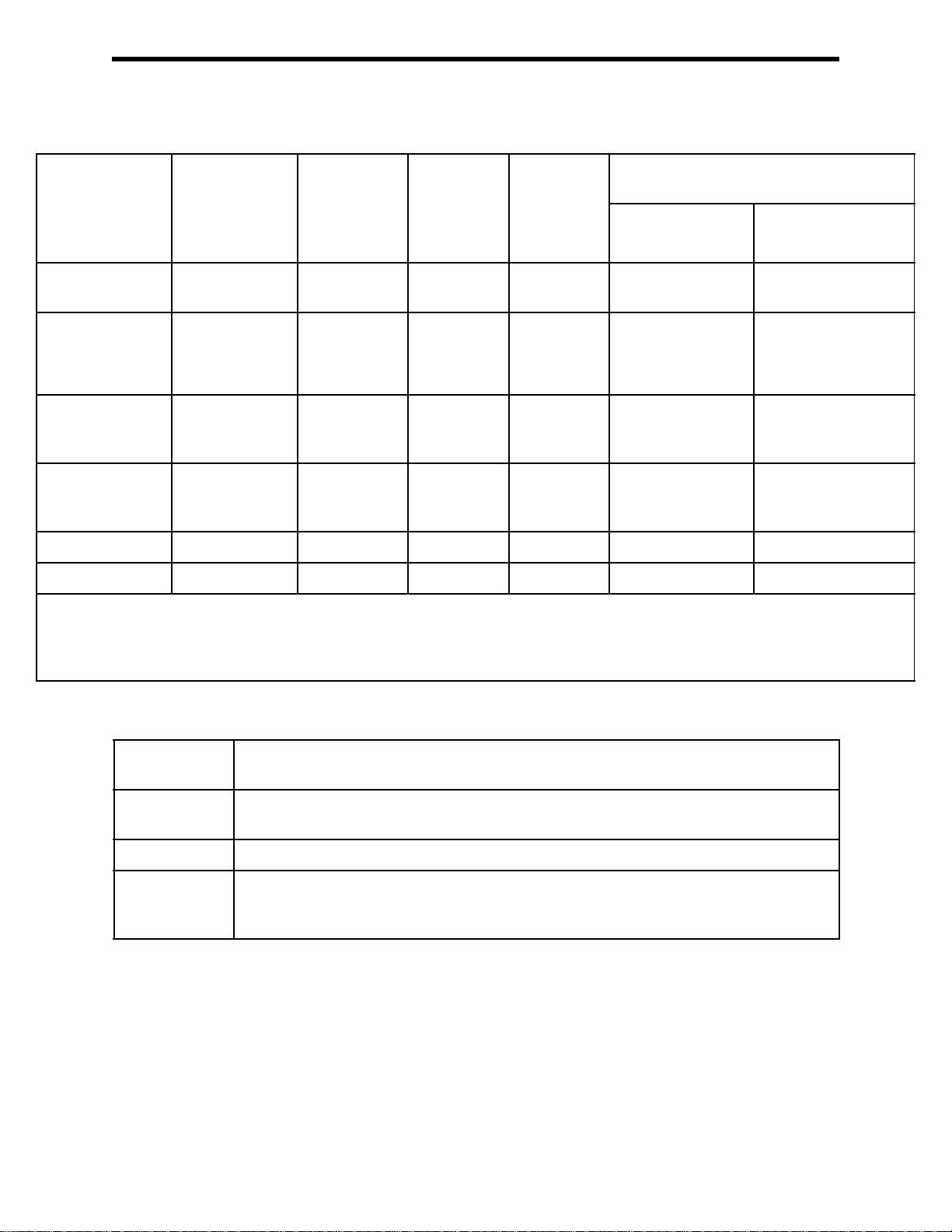
Table 1: Standard Sensor Specifications/Alarm Points
Combustible
Gas, Methane
(CH
)
4
Calibration
Standard**
Detection
Range
Reading
Increment
Alarm 1
Factory Setting
Alarm 2
Factory Setting
STEL Alarm n/a n/a 5.0 ppm 200 ppm n/a 60.0 ppm
TWA Alarm n/a n/a 1.0 ppm 25 ppm n/a 40.0 ppm
* When calibrating the GX-6000 with the Auto Calibration or the Single Calibration method, the calibration gas value must be
equal to or higher than the alarm 1 setting. See “Updating the Alarm Point Settings (ALARM POINTS)” on page 145 for
instructions to change the alarm points if necessary for the desired calibration gas value.
** Although calibrated to a specific gas, these sensors will respond to a variety of gases.
0 - 100 %LEL 0 - 40
1 %LEL 0.1 volume% 0.5 ppm 1 ppm • 0 - 5000:
10 %LEL* 19.5
50 %LEL 23.5
Oxygen (O
volume%
volume%,
decreasing*
volume%,
increasing
) Hydrogen
2
Sulfide
(H
S)
2
0 - 100.0
ppm
5.0 ppm* 25 ppm* 5000 ppb* 400 ppm*
30.0 ppm 50 ppm 10000 ppb 1000 ppm
Carbon
Monoxide
(CO)
0 - 500
ppm
VOCs, Isobutylene Calibration
Standard**
Low Range PID High Range PID
0 - 50000 ppb 0 - 6000 ppm
1 ppb
• 5000 - 50000:
10 ppb
• 0 - 600 ppm:
0.1 ppm
• 600 - 6000 ppm: 1
ppm
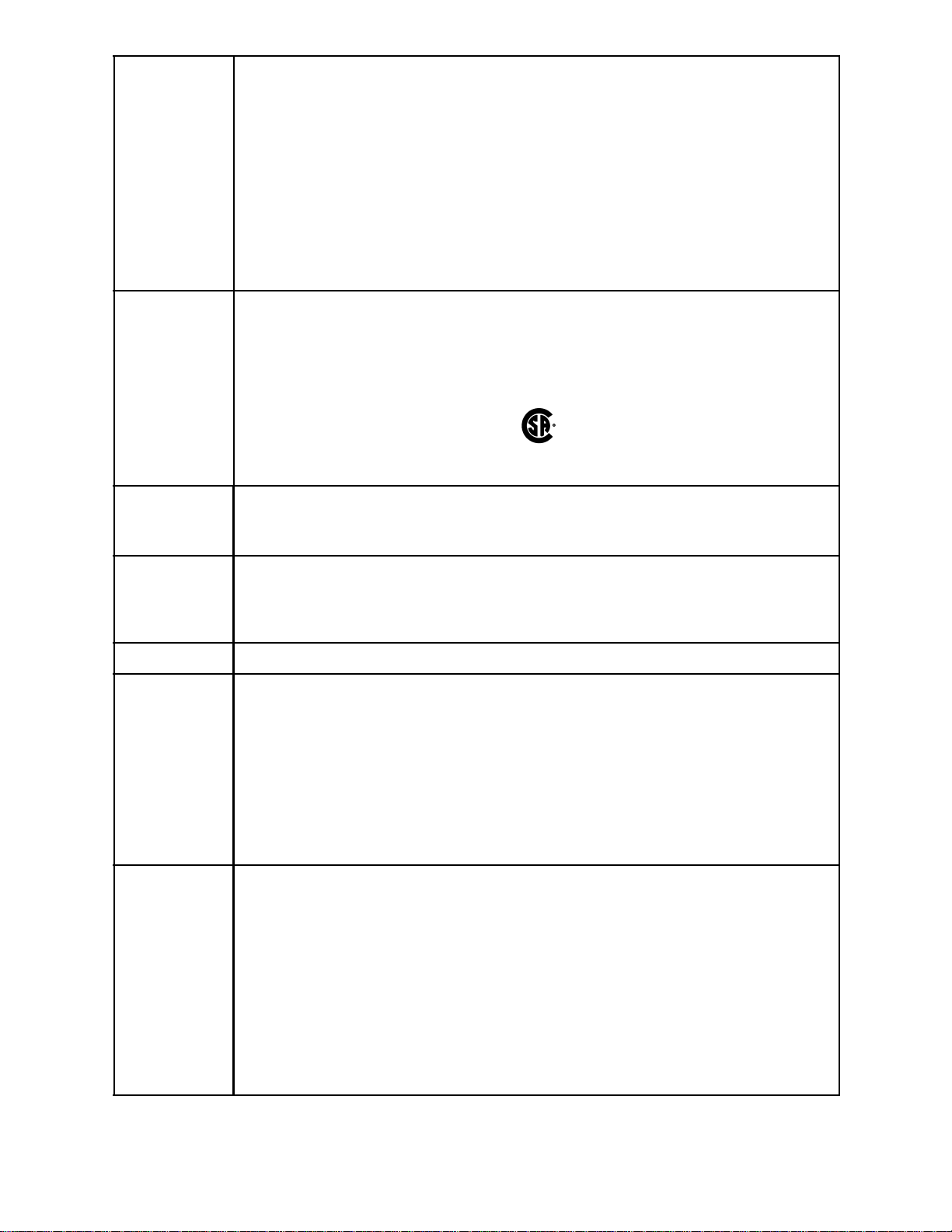
Table 2: GX-6000 Specifications
Sampling
Method
Response
Time
Display Graphics LCD Display
Operating
Temperature
& Humidity
Sample Draw
T90 Within 30 Seconds
-20°C to 50
°
C/Below 95% RH (Without Condensation)
12 • Chapter 1: Introdu ction GX-6000 Operator’s Manual
Page 13
Indication
Accuracy
Combustible Gas (LEL), Catalytic Type Sensor
• -10°C to 40
• -20°C to 50
°
C: 5% of full scale
°
C: 6% of full scale
Oxygen
•± 0.5% O
2
Hydrogen Sulfide
• ± 5% of reading or ± 2 ppm H
S (whichever is greater)
2
Carbon Monoxide
• ± 5% of reading or ± 5 ppm CO (whichever is greater)
PID
• ± 10% of reading or ± 1 increment (whichever is greater)
Safety/
Regulatory
• ATEX: II 1 G Ex ia IIC T4 Ga
Certificate Number Presafe 15ATEX6171
• IECEx: Ex ia IIC T4 Ga
Certificate Number PRE 15.0011
• CSA classified, “C/US”, as Intrinsically Safe. Exia. Class I, Groups A, B, C, & D.
Temperature Code T3A.
C US
186718
Power Supply • Three AA size alkaline batteries
OR
• One lithium ion battery pack
Continuous
Operating
• Alkaline Batteries: 8 Hours (Non Alarm Operation, Fully Charged)
• Li-ion Battery Pack: 14 Hours (Non Alarm Operation, Fully Charged)
Hours
@ 25 °C
Case High-impact Plastic, RF Shielded, Dust and Weather Proof
Included
Accessories
• Belt clip
• Rubber boot
• Wrist strap
• Tapered nozzle
• Screen protector
• 3 foot hose and probe
• VOC zero filter (included for instruments with a low range PID sensor, a 10.0 eV/
benzene PID sensor, an 11.7 eV PID sensor or any PID/IR CO
• Dehumidifier filter (included for instruments with an 11.7 eV PID sensor)
combination)
2
Other
Accessories
• Alkaline Battery Pack
• Rechargeable Li-ion Battery Pack
• 115 VAC Charger
• 12 VDC Charger
• Hose/Probes of Various Lengths, See “Chapter 7: General Parts List” on page 128.
• VOC Zero Filter (optional for instruments with a high range PID sensor)
• Dilution Fitting (1:1)
• DIN Rail Mounting Assembly (for mounting chargers to the wall)
®
• Product CD, includes Data Logger Management Program (Windows
7, 8, and 10)
• IrDA/USB Cable for connecting to a computer when using the Data Logger
Management Program (not needed if computer has an infrared port)
GX-6000 Operator’s Manual Chapter 1: Introduction • 13
Page 14

Dimensions
and Weight
Approximately 200(H) x 68(W) x 52(D) mm (7.9”H x 2.7”W x 2.0”D)
Approximately 400 g (14 oz.)
About this Manual
Although the GX-6000 can support up to 6 sensors, this manual specifically describes an
instrument with the four standard sensors and a PID sensor. See the appendices for
descriptions of other sensors.
The GX-6000 Operator’s Manual uses the following conventions for notes, cautions, and
warnings.
NOTE: Describes additional or critical information.
CAUTION: Describes potential damage to equipment.
WARNING: Describes potential danger that can result in injury or death.
14 • Chapter 1: Introdu ction GX-6000 Operator’s Manual
Page 15
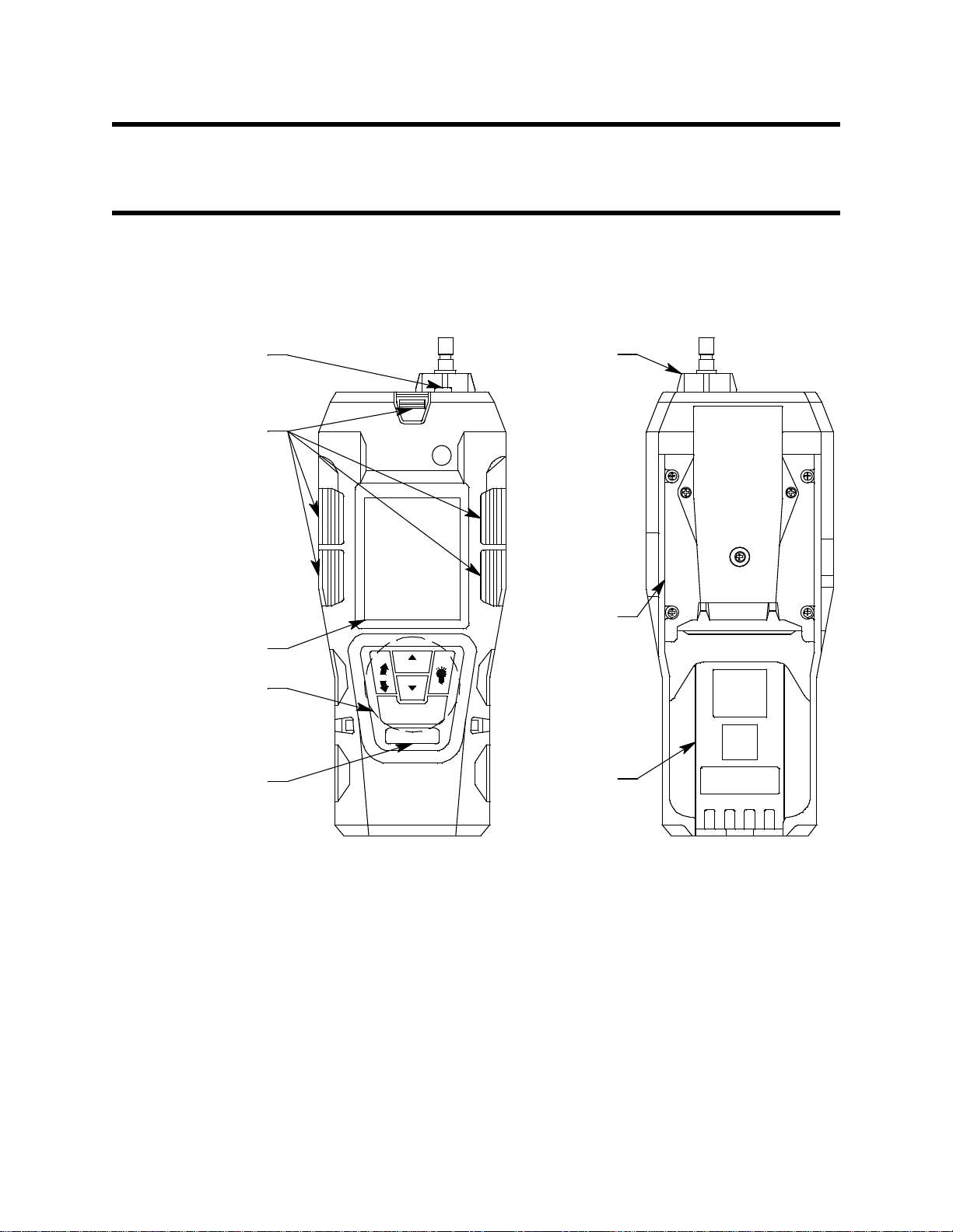
Chapter 2: Description
Inlet Filter
Holder
Flow
Chamber
Battery
Pack
Flashlight LED
Alarm L EDs
RKI GX-6000
DISP
LOCK
(PANI C)
AIR
SHIFT
RESE T
Infrared
Communications
Port
Control Buttons
LC D
POWER/ENTER
Overview
This chapter describes the GX-6000 instrument and accessories.
Instrument Description
The GX-6000 includes the case, LCD, control buttons, flashlight LED, alarm LEDs,
infrared communication port, buzzer, vibrator, printed circuit board, pump, flow chamber,
sensors, filters, inlet filter holder, and batteries.
GX-6000 Operator’s Manual Chapter 2: Description • 15
Figure 1: Component Location
Case
The GX-6000’s sturdy, high-impact plastic case is radio frequency (RF) resistant and is
suitable for use in many environmental conditions, indoors and out. The case is dust proof
and water resistant. A clear plastic window is located on the front of the case. The battery
pack and flow chamber are located on the back of the GX-6000. The inlet filter holder is
located on the top of the GX-6000 case.
LCD
A digital LCD (liquid crystal display) is visible through a clear plastic window in the top
case. The LCD simultaneously shows the gas reading for all installed sensors. The LCD
also shows information for each of the GX-6000’s operating modes.
Page 16

Control Buttons
Five control buttons are located below the LCD. They are, from left to right and top to
bottom, DISP/LOCK, ▲AIR, SHIFT ▼ (PANIC), POWER/ENTER, and RESET.
Table 3: GX-6000 Control Button Functions
Button Function(s)
DISP/LOCK • activates Display Mode
• enters instructions into the GX-6000’s microprocessor
• allows you to exit a menu without saving changes
• locks screen orientation in any mode if INVERSION SELECT is set
to ON
▲AIR • activates the demand zero function (adjusts the GX-6000’s fresh air
SHIFT ▼ (PANIC) • enters instructions into the GX-6000’s microprocessor
POWER/ENTER • turns the GX-6000 on and off
RESET • silences and resets audible alarm if ALARM LATCHING is set to
reading)
• enters instructions into the GX-6000’s microprocessor
• moves the cursor on the LCD up the screen
• increases the value of a parameter available for adjustment
• scrolls through parameter options
• moves the cursor on the LCD down the screen
• decreases the value of a parameter available for adjustment
• scrolls through parameter options
• initiates a Panic alarm in any mode if PANIC is set to ON
• enters instructions, values, and settings into the GX-6000’s
microprocessor
LATCHING and ALARM SILENCE is set to ON
• turns the flashlight LED on and off
Flashlight LED
A white LED is visible through a round, raised, frosted lens in the top of the case. This
LED can be used to provide extra light, if necessary. The RESET button turns this LED on
and off.
Alarm LEDs
Five sets of red alarm LEDs (light emitting diodes) border the LCD. The alarm LEDs alert
you to gas, low battery, and failure alarms.
Infrared Communications Port
An infrared (IR) communications port is located on the front of the case, below the
POWER/ENTER button. The data transmitted through the port is in standard IrDA
protocol. A computer’s infrared port or an IrDA/USB cable connected to a USB port can
be used to download data saved by the GX-6000 to a computer using the GX-6000 Data
Logger Management Program. See the GX-6000 Data Logger Management Program
operator’s manual for data logging and downloading instructions.
Buzzer
One solid-state electronic buzzer is located inside the case. Holes on the top front of the
case allow the sound to exit the case. The buzzer sounds for gas alarms, malfunctions, low
battery voltage, and as an indicator during use of the GX-6000’s many display and
16 • Chapter 2: Description GX-6000 Operator’s Manual
Page 17

adjustment options.
Vibrator
A vibrating motor inside the GX-6000 case vibrates for gas alarms, unit malfunctions, and
as an indicator during normal use of the various modes of the GX-6000.
Printed Circuit Boards (PCBs)
The GX-6000 printed circuit boards analyze, record, control, store, and display the
information collected. The circuit boards are located inside the case. They are not user
serviceable.
Pump
A diaphragm pump inside the GX-6000 draws the sample to the sensors. It can draw
sample from as far as 50 feet from the GX-6000. The pump is not user serviceable.
CAUTION: Sample hose lengths of more than 50 feet are not recommended for the
GX-6000 because of flow rate reduction.
Flow Chamber
The flow chamber is on the back of the GX-6000 and is held in place by four Phillips
screws. The flow chamber seals to the rubber sensor gasket which seals to the sensor faces
inside the GX-6000 and routes flow from the pump to the sensors and to the exhaust port
(on the top of the GX-6000 case).
Sensors
The GX-6000 uses five sensors to monitor combustible gas, oxygen (O2), carbon
monoxide (CO), hydrogen sulfide (H
sensors are located inside the GX-6000 and are held in their sockets by the flow chamber.
The sensors use different detection principles, as described below.
Combustible Gas Sensor
The % LEL sensor detects combustible gas in the % LEL range. It uses a catalytic element
for detection. The reaction of gas with oxygen on the catalyst causes a change in the
resistance of the element which affects the current flowing through it. The current is
amplified by the GX-6000’s circuitry, converted to a measurement of combustible gas
concentration, and displayed on the LCD.
The standard calibration for the combustible gas sensor is to methane but the sensor will
still detect and respond to a variety of combustible gases.
Oxygen Sensor
The O
diffuse into the cell at a rate proportional to the partial pressure of oxygen. The oxygen
reacts in the cell and produces a voltage proportional to the concentration of oxygen. The
voltage is measured by the GX-6000’s circuitry, converted to a measurement of gas
concentration, and displayed on the LCD.
sensor is a galvanic type of sensor. A membrane covers the cell and allows gas to
2
S), and isobutylene (IBL) simultaneously. The
2
GX-6000 Operator’s Manual Chapter 2: Description • 17
Page 18

CO and H2S Sensors
The CO and H2S sensors are electrochemical cells that consist of two precious metal
electrodes in a dilute acid electrolyte. A gas permeable membrane covers the sensor face
and allows gas to diffuse into the electrolyte. The gas reacts in the sensor and produces a
current proportional to the concentration of the target gas. The current is amplified by the
GX-6000’s circuitry, converted to a measurement of gas concentration, and displayed on
the LCD.
PID Sensor
Two types of PID sensors can be used with the GX-6000, a low range (higher sensitivity)
sensor and a high range (lower sensitivity) sensor (see Table 1 for specifications).
The PID sensor is a cylindrical sensor with a diffusion opening on the front and 3 pins on
the back. It is installed in a white housing that has three sockets on the bottom that mate
with the GX-6000 instrument. The PID sensor must always be installed in the first smart
sensor position which is located in the top left corner of the sensor block.
The standard calibration for a PID channel is to isobutylene. A PID channel can be factory
setup for and calibrated to other gases. Regardless of the calibration gas, the PID channel
will still detect and respond to a variety of volatile organic compounds (VOCs). Consult
RKI Instruments, Inc. for other available PID configurations and to specify the desired
PID configuration when a unit is ordered.
Dummy Sensors
Any unit that has less than 6 sensors will have a dummy sensor installed in one or more
unused sensor positions. Dummy sensors are factory installed. The flat top of the dummy
sensor should face up and the bottom hollow side should face down.
Filters
An H2S removal filter disk is placed into a recess in the sensor gasket over the %LEL
sensor. It prevents H2S in the ambient air from reaching the unit’s combustible gas sensor.
Removing H2S that is present in the monitored air prolongs the life of the sensor. The H2S
filter disk is dark red in color and although it may darken over time, its color is not
indicative of remaining filter life. The H2S filter disk can absorb H2S for 33 ppm hours
and should be replaced after that much exposure. With this many ppm hours of absorption,
the H2S filter disk should be replaced after 80 minutes of exposure to 25 ppm H2S. This
equates to replacing the H
containing 25 ppm H2S. If H2S exists in the monitoring environment, the H2S filter disk
will have to be replaced more frequently.
A charcoal filter is placed into a recess in the sensor gasket over the CO sensor. The
charcoal filter is black, has a woven texture, and is impregnated with an H2S absorbing
material. The CO sensor will respond if exposed to H2S and certain hydrocarbon gases.
The charcoal filter disk scrubs these gases out of the sample to avoid false CO readings. If
false or elevated CO readings are noticed, especially in the presence of H2S, change the
charcoal filter.
S filter disk after 40 2-minute calibrations with a cylinder
2
18 • Chapter 2: Description GX-6000 Operator’s Manual
Page 19

Inlet Filter Holder
The filter holder is a clear plastic dome shaped piece on the top of the case. A male quick
connect fitting is located on the inlet filter holder. This is the GX-6000’s inlet fitting. The
filter holder may be removed by turning it counterclockwise and pulling it away from the
case. One flat membrane disk hydrophobic filter, a wire mesh disk, and a rubber filter
retaining gasket are held in place by the filter holder and are located in the bottom of the
case chamber where the filter holder is installed.
Batteries
Three AA-size alkaline batteries or a rechargeable lithium ion battery pack (4.1 VDC)
power the GX-6000. Instrument run time is dependent upon battery type. At 25°C the
alkaline batteries last at least 8 hours and the lithium ion battery pack lasts at least 14
hours. The battery icon in the upper right of the LCD shows remaining battery life.
When the GX-6000 detects a low battery voltage, a low battery warning is activated.
When battery voltage is too low for Measuring Mode, the GX-6000 sounds a dead battery
alarm.
The alkaline batteries can be replaced by removing the battery cover on the back of the
case. The lithium ion pack can be replaced by removing the entire battery pack. The
battery pack release latch is located on the bottom of the instrument. When viewing the
instrument from the bottom with the LCD facing down, push the battery pack release latch
toward the right to release the pack.
The lithium ion battery pack can be recharged by placing the GX-6000 in its battery
charging station or by placing the battery pack in the charging station.
NOTE: Use of batteries or battery chargers not specified by RKI Instruments, Inc. will
compromise the CSA classification and may void the warranty. See “Replacing
or Recharging the Batteries” on page 102.
WARNING: To prevent ignition of a hazardous atmosphere, batteries must only be
changed or charged in an area known to be nonhazardous.
AVERTISSEMENT:Pour éviter l’inflammation d’une atmosphère dangereuse, les
batteries doivent uniquement être modifiés ou facturés dans une zone
connue comme non dangereuse.
GX-6000 Operator’s Manual Chapter 2: Description • 19
Page 20

Included Accessories
Included accessories consist of the tapered rubber nozzle, belt clip, rubber boot, wrist
strap, and the sample hose/probe.
Tapered Rubber Nozzle
A cone shaped 4 inch long rubber nozzle is included with the GX-6000 as standard. It can
be installed on the inlet fitting by pushing the larger end over it. The smaller end can be
inserted through a hole in a wall or some other access to an enclosed area to sample the
environment.
Belt Clip
A belt clip can be mounted to the back of the case using 3 Phillips head screws. The belt
clip allows the GX-6000 to be securely attached to a belt.
Rubber Boot
A protective rubber boot can be installed over the GX-6000.
Wrist Strap
A wrist strap is included with the GX-6000 and can be attached to the right or left wrist
strap installation feature on the GX-6000 case.
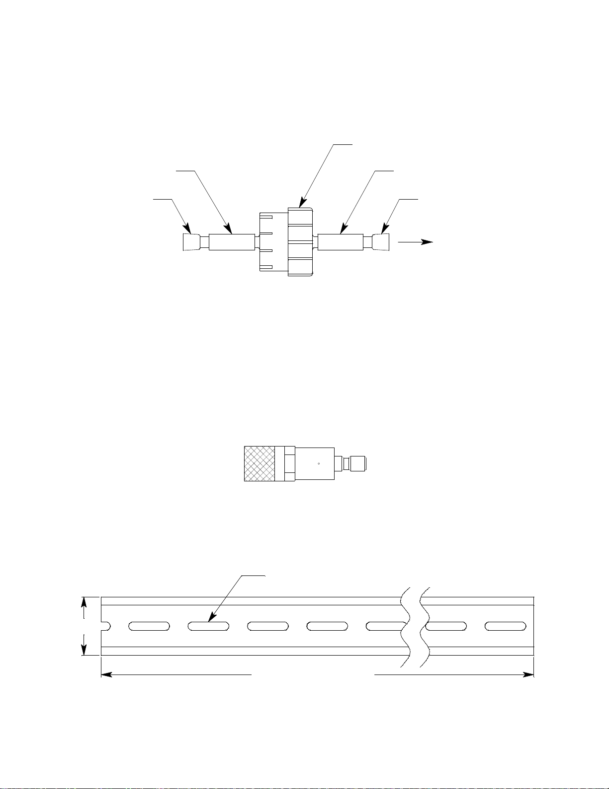
Sample Hose and Probe
A 3 foot sample hose with an attached probe is standard with the GX-6000. When desired,
the rubber nozzle may be removed and the sample hose and probe may be connected to the
inlet fitting. Sample hose lengths are available from 3 feet to 50 feet (see “Chapter 7:
General Parts List” on page 128). The quick connect end of the sample hose connects to
the inlet fitting of the GX-6000. The probe is integral with the hose and connects to it with
a tube fitting.
CAUTION: Sample hose lengths of more than 50 feet are not recommended for the GX-
6000 because of flow rate reduction.
The probe includes a replaceable particle filter and hydrophobic filter disk that prevent
particulates and water from entering the GX-6000’s flow system. See “Replacing the
Probe’s Particle Filter and Hydrophobic Filter Disk” on page 110 for instructions to
replace the particle filter and hydrophobic filter disk.
Figure 2: Sample Hose and Probe
20 • Chapter 2: Description GX-6000 Operator’s Manual
Page 21

Screen Protector
The clear screen protector can be installed over the GX-6000’s LCD to prevent it from
getting scratched.
1 . Remove the GX-6000’s rubber boot.
2 . Orient the GX-6000 so that the LCD is as horizontal as possible.
3 . Clean the LCD with rubbing alcohol.
4 . Place 1 drop of water in the center of the LCD.
5 . Grasp the tab at the top of the screen protector’s backing and pull it away from the
screen protector.
6 . Use needle-nose pliers or tweezers to handle the screen protector.
7 . Align the top of the screen protector with the top of the “RKI GX-6000” logo.
8 . Press down on the center of the screen protector. Water should spread out along the
entire surface of the screen protector between the screen protector and the LCD.
Some of the water may come out the edges.
9 . If you are unhappy with the initial placement of the screen protector, lift the screen
protector up from a corner. Quickly rearrange the screen protector and set it back
down on the LCD.
10 . Use a small, stiff piece of plastic and, working your way out from center, remove any
air bubbles. The screen protector may shift during this process so be sure to hold it
securely with your other hand.
11 . Allow enough time for the water between the screen protector and the LCD to dry
before handling the GX-6000.
12 . Reinstall the rubber boot.
Other Accessories
Several other accessories are available for the GX-6000. This section describes the VOC
zero filter, the dilution fitting, and the DIN rail. Detailed instructions regarding the use of
the dilution fitting are included in other parts of this manual. Data logging accessories are
briefly described in “Data Logging” on page 67.
VOC Zero Filter
A VOC zero filter is included as standard with GX-6000s that include:
• Low range PID sensor (PID-001L)
• 10.0 eV/benzene PID sensor (PID-003L)
• 11.7 eV PID sensor (PID-004)
• Any PID sensor and any CO2 sensor
The VOC zero filter scrubs out low levels of VOC gases using charcoal. Use the VOC
zero filter when:
• Performing an air adjust on a PID sensor in an area that may have a low-level VOC
background.
• Performing an air adjust on a PID/CO
scrubber).
GX-6000 Operator’s Manual Chapter 2: Description • 21
instrument (in combination with a CO2
2
Page 22
The filter comes with a tubing stub and plug on each end. Both plugs must be removed
Filter
Plug
Tubing StubTubing Stub
Plug
To GX-6000
4" fo r 1 - Ch ar ge r Mo del
14" for 4- C har g e r M o de l
Use #10 Screws to Mount
1.38"
before using the filter and must be reinstalled for storage. The filter does not have a
preferred flow direction.
When used with a CO2 scrubber, the VOC zero filter gets connected to the instrument and
the CO2 scrubber gets connected to the VOC zero filter. See “Performing a Demand Zero
for Instruments with a Carbon Dioxide Sensor and a PID Sensor” on page 203 for more
instructions.
Figure 3: VOC Zero Filter
External Dilution Fitting
A 1:1 external dilution fitting is available for the GX-6000. It is designed to mate with the
inlet fitting and accept the sample hose and probe. The fitting is made with brass and
nickel plated brass and is appropriate for use with the four standard gases. The fitting is
normally used when it is necessary to introduce air into a sample that has no oxygen or a
very low level of oxygen, such as a nitrogen purged sample. It can also be used when one
of the target gas levels in the sample area will likely be present in a concentration above
the detection range for that gas. Since the fitting partially consists of unplated brass, it is
not appropriate for detection of elevated levels of H
such as Cl2 or SO2.
S or of gases that are easily absorbed
2
Figure 4: 1:1 Dilution Fitting
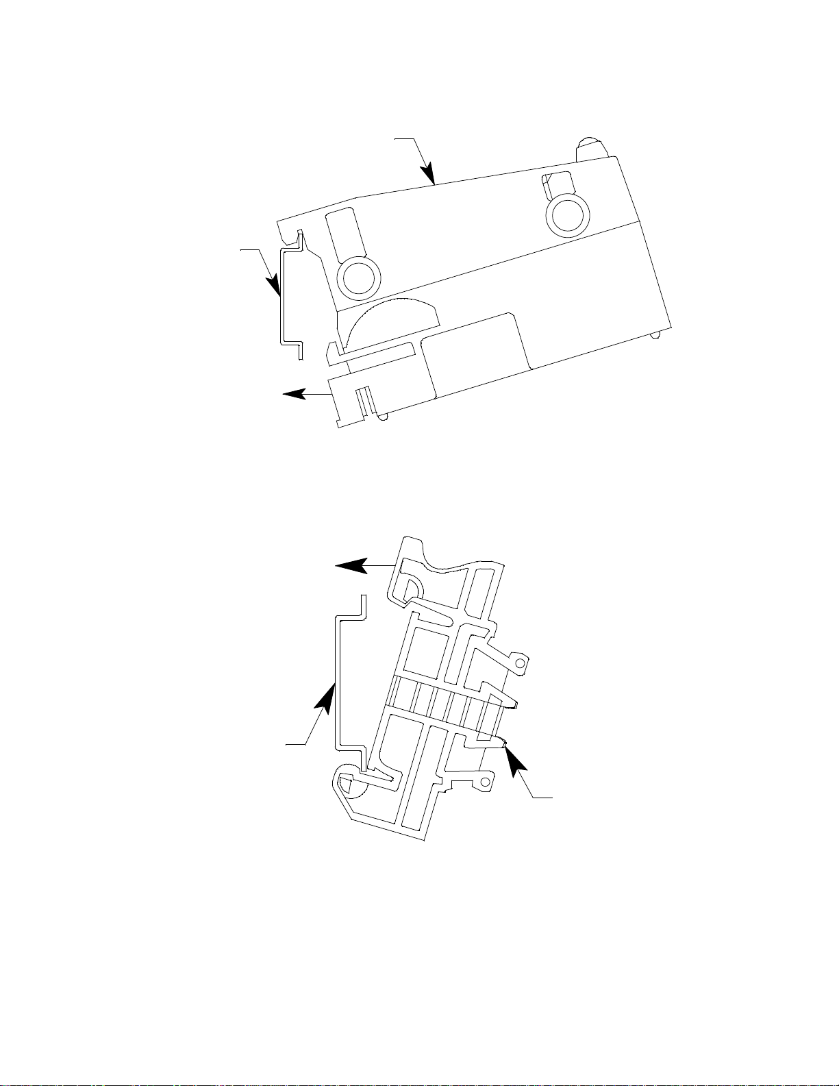
DIN Rail Mounting Assembly
Two different DIN rail mounting assemblies are available for the GX-6000’s charger. Each
assembly has two end clamps but one assembly is long enough to accommodate 1 charger
and the other assembly is long enough to accommodate 4 chargers.
Figure 5: DIN Rail Dimensions
22 • Chapter 2: Description GX-6000 Operator’s Manual
Page 23
1 . Use #10 screws to mount the DIN rail to the wall.
DIN Rail
Charger
Clamp
DIN Rail
2 . Install the charger(s) on the DIN rail. Seat the top of the DIN rail in the top slot on
the back of the charger. Press the bottom of the charger toward the DIN rail until it
locks into place.
Figure 6: Installing a Charger on the DIN Rail
3 . Slide the charger(s) along the DIN rail into the desired position.
4 . Install the end clamps on the left and right side of the charger or bank of chargers to
prevent sliding.
Figure 7: Clamp Installation
GX-6000 Operator’s Manual Chapter 2: Description • 23
Page 24
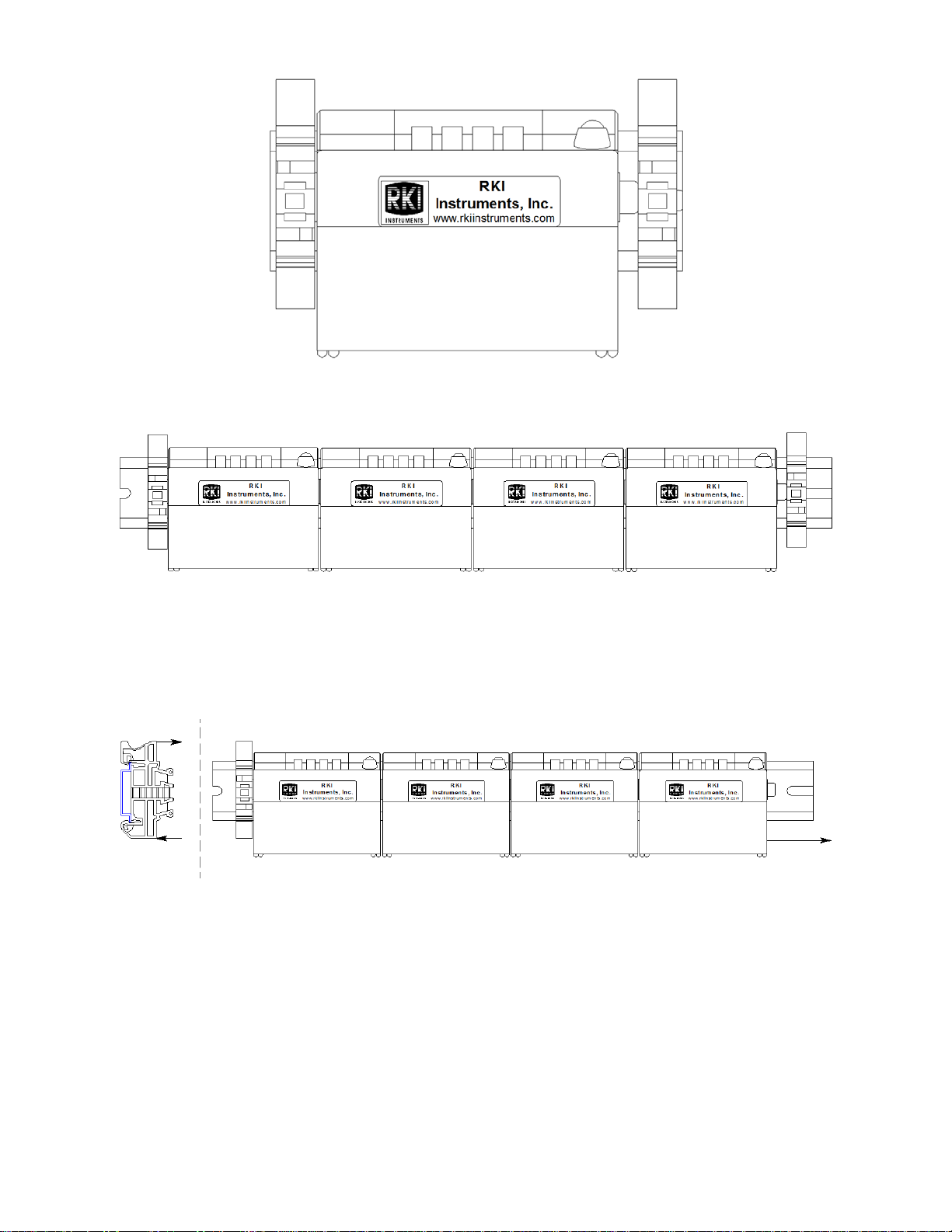
Figure 8: 1-Charger Installation
Figure 9: 4-Charger Installation
5 . To remove any charger(s) from the DIN rail:
a. Remove the clamps by pushing on the bottom of the clamp and pulling on the top
of the clamp.
b. Slide the charger(s) off the DIN rail.
Figure 10: Charger Removal
24 • Chapter 2: Description GX-6000 Operator’s Manual
Page 25

Chapter 3: Operation
Overview
This chapter explains how to use the GX-6000 to perform confined space entry
monitoring or general area monitoring in Normal Mode. There are three operational
modes in Normal Mode: Measuring Mode, Display Mode, and Calibration Mode. While
in Normal Mode, the unit is normally operating in Measuring Mode. Display Mode and
Calibration Mode are accessible from Measuring Mode. Display Mode is described in this
chapter. Calibration Mode is described in “Chapter 4: Calibration Mode” on page 69.
The GX-6000 can also operate in Leak Check Mode and Bar Hole Mode. See “Appendix
H: 10.0 eV/Benzene PID Sensor” for operating instructions for Leak Check Mode. See
“Appendix D: Using the GX-6000 in Bar Hole Mode” on page 175 for operating
instructions for Bar Hole Mode.
Start Up
This section explains how to start up the GX-6000, get it ready for operation, and turn it
off.
NOTE: The screens illustrated in this section are for a standard 4-gas + high range PID
unit. The screens displayed by your GX-6000 may be slightly different.
Turning On the GX-6000
To illustrate certain functions, the following description of the GX-6000 start up sequence
assumes that the following menu items in Maintenance Mode are turned on: LUNCH
BREAK, CAL REMINDER, BUMP REMINDER, and ID DISPLAY. If any of these
items are turned off, then the corresponding screens will not appear.
The GX-6000 may be used with a sample hose and probe or with the tapered rubber
nozzle. Determine which configuration works best for your application.
NOTE: When the sample hose is not being used, its outgassing characteristics may
result in a small buildup of gas to which the PID sensor will respond. If a
sample hose has been sitting unused for a period of time, when that sample hose
is connected to a GX-6000, the PID channel may temporarily show a reading.
The reading will return to a fresh air reading after all of the built up gas has
been drawn out of the sample hose.
1 . Connect the tapered rubber nozzle or the sample hose and probe to the GX-6000’s
quick connect inlet fitting.
2 . Press and briefly hold down the POWER/ENTER button. Release the button when
you hear a beep.
GX-6000 Operator’s Manual Chapter 3: Operation • 25
Page 26
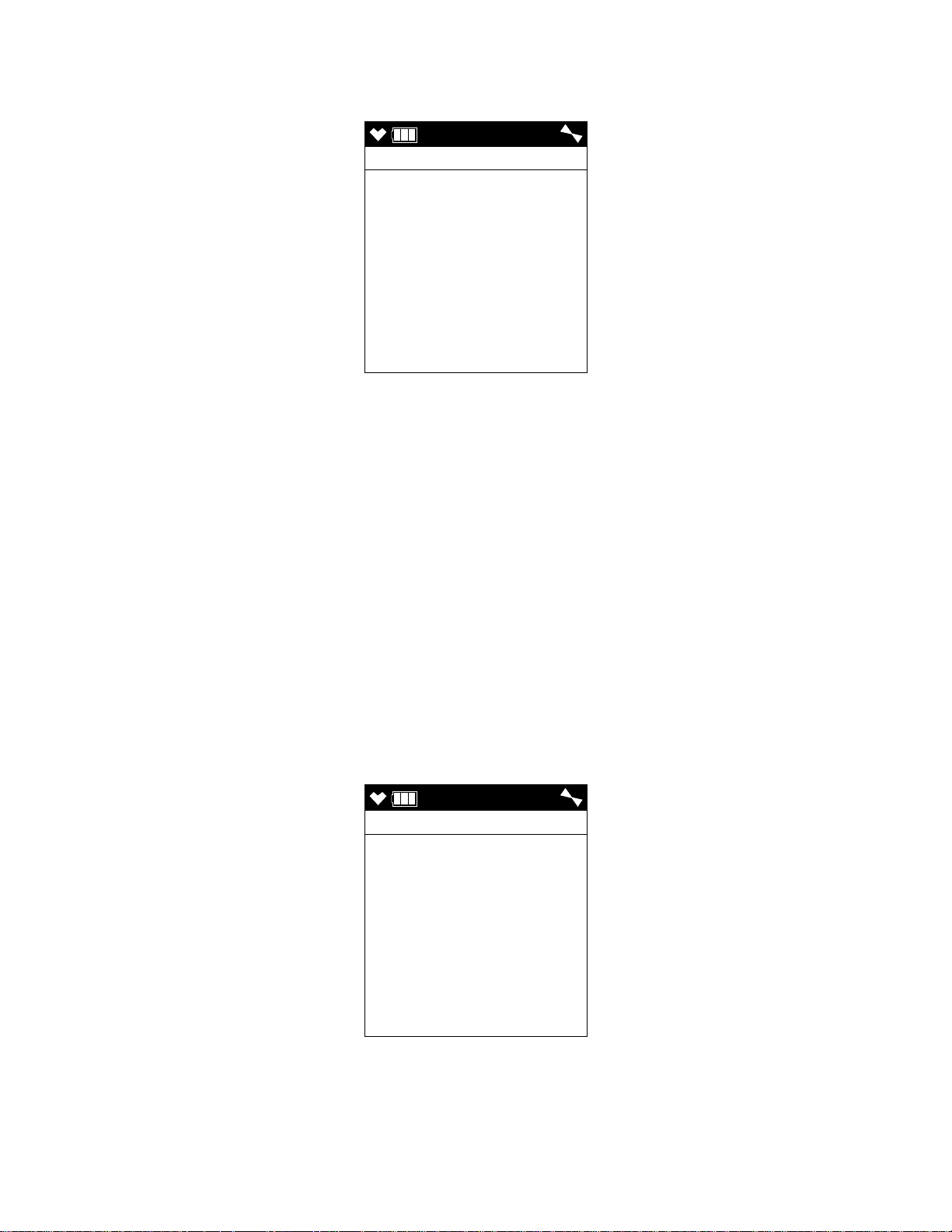
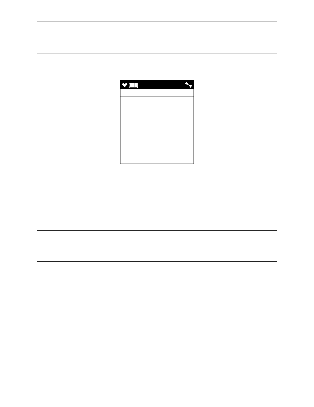
3 . If LUNCH BREAK is turned on (see “Updating the Lunch Break Setting (LUNCH
4:07
LUNCH BREAK
5 SEC
YES:ENTER
NO:DISP
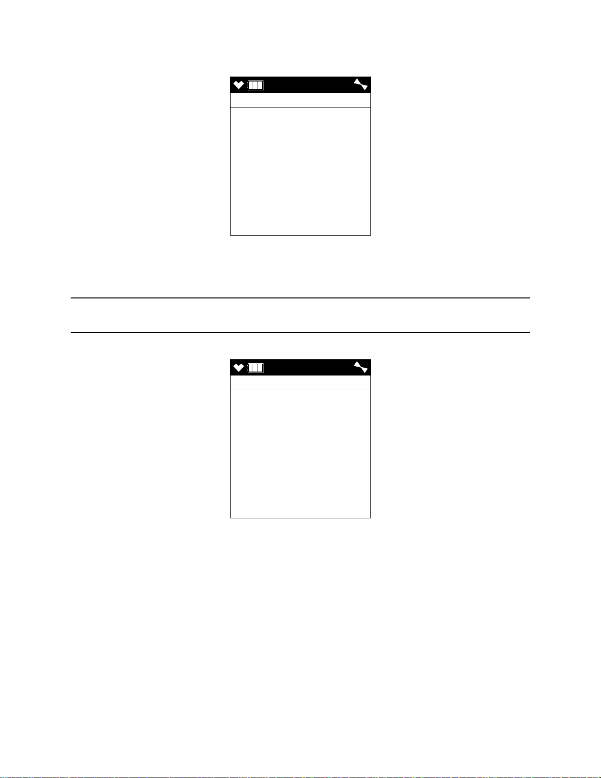
4:07
CAL DATE PAST
CONFIRM TO USE
CAL MODE : ENTER
NO : RESET
BREAK)” on page 149), the Lunch Break Screen appears. The unit counts down
from 5 seconds at the top of the screen.
• To continue accumulating peak and time-weighted average (TWA) readings from
the last time the GX-6000 was used, press and release the POWER/ENTER
button before the countdown reaches 0 or allow the countdown to reach 0. If you
do not press the POWER/ENTER button within the 5 second countdown, the
GX-6000 automatically resumes accumulating the peak and TWA readings. The
GX-6000 will also continue to keep track of operating time including the
operating time from the last time the GX-6000 was used. See “Time in Operation
Screen” on page 54 for more information about how the GX-6000 tracks the
operating time. The short-term exposure limit (STEL) reading is reset each time
the GX-6000 is turned on.
• To reset the accumulation of these measurements, press and release the DISP/
LOCK button before the countdown reaches 0.
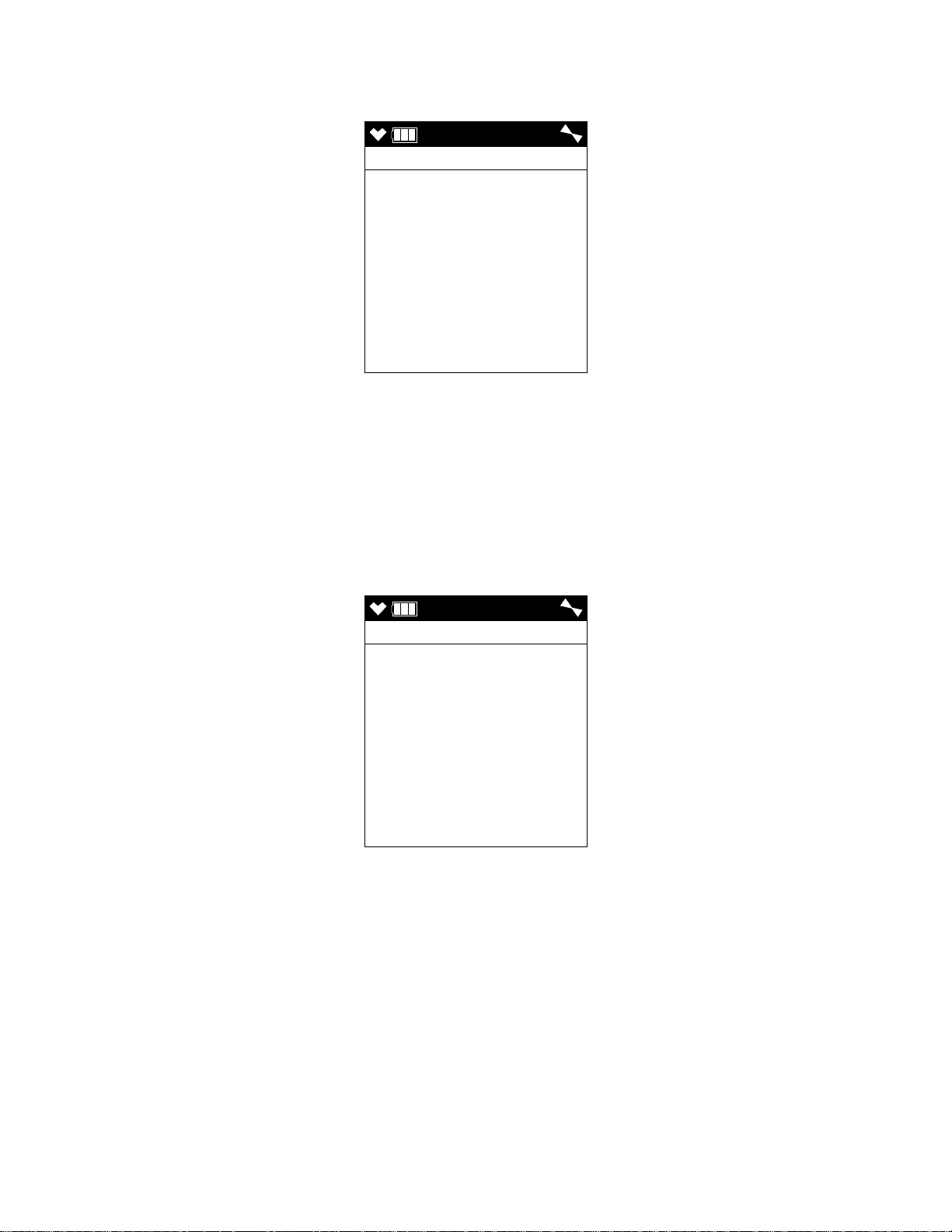
4 . If CAL REMINDER is set to ON, the screen that appears next depends on how
CAL EXPRD is set in Maintenance Mode (see “Updating the Calibration Expired
Setting (CAL EXPRD)” on page 140).
• If the unit is due for calibration and CAL EXPRD is set to CONFIRM TO
USE, then the following screen displays and the buzzer sounds in a double
pulsing pattern.
To perform a calibration, press and release the POWER/ENTER button. The
GX-6000 will enter Calibration Mode and the LCD will show the Calibration
Mode main menu. See “Chapter 4: Calibration Mode” on page 69 for
26 • Chapter 3: Operation GX-6000 Operator’s Manual
Page 27

instructions to calibrate the GX-6000. When you are done with the calibration
4:07
CAL DATE PAST
CANNOT USE
CAL MODE : ENTER
and exit Calibration Mode, the unit will begin the startup sequence. If the
calibration was successful, the screen above will not appear again until the unit is
due for calibration. If the calibration was not successful, the screen above will
again appear in the startup sequence.
To continue without performing a calibration, press and release the RESET
button.
• If the unit is due for calibration and CAL EXPRD is set to CANNOT USE, then
the following screen displays and the buzzer sounds in a double pulsing pattern.
The GX-6000 cannot be used until a successful calibration has been performed.
Press and release the POWER/ENTER button to enter Calibration Mode. See
“Chapter 4: Calibration Mode” on page 69 for instructions to calibrate the GX-
6000.
NOTE: In this situation, even if the User password function has been turned on, no
password is required to perform a calibration.
When you are done with the calibration and exit Calibration Mode, the unit will
begin the startup sequence. If the calibration was successful, the screen above
will not appear again until the unit is due for calibration. If the calibration was
not successful, the screen above will again appear in the startup sequence.
GX-6000 Operator’s Manual Chapter 3: Operation • 27
Page 28
• If the unit is due for calibration and CAL EXPRD is set to NO EFFECT, then
4:07
CAL DATE PAST
NO EFFECT
CAL MODE : ENTER
4:07
BUMP DATE PAST
CONFIRM TO USE
CAL MODE : ENTER
NO : RESET
the following alert screen displays and the buzzer sounds in a double pulsing
pattern.
If you want to enter Calibration Mode, press and release the POWER/ENTER
button. If you do not want to enter Calibration Mode, wait for the instrument to
continue with its startup sequence.
5 . If BUMP REMINDER is set to ON (factory setting is OFF), the screen that appears
next depends on how BUMP EXPRD is set in Maintenance Mode (see “Updating
the Bump Expired Setting (BUMP EXPRD)” on page 144).
• If the unit is due for bump testing and BUMP EXPRD is set to CONFIRM TO
USE, then the following screen displays and the buzzer sounds in a double
pulsing pattern.
To perform a bump test, press and release the POWER/ENTER button. The GX6000 will enter Calibration Mode and the LCD will show the Calibration Mode
main menu. See “Chapter 4: Calibration Mode” on page 69 for instructions to
bump test the GX-6000. When you are done with the bump test and exit
Calibration Mode, the unit will begin the startup sequence. If the bump test was
successful, the screen above will not appear again until the unit is due for bump
testing. If the bump test was not successful, the screen above will again appear in
the startup sequence.
To continue without performing a bump test, press and release the RESET
button.
28 • Chapter 3: Operation GX-6000 Operator’s Manual
Page 29
NOTE: If BUMP DISP is set to OFF, the bump test menu item will not appear in
4:07
BUMP DATE PAST
CANNOT USE
CAL MODE : ENTER
Calibration Mode even though the instrument is prompting you to perform a
bump test. A bump test can always be performed in Maintenance Mode, if
necessary.
• If the unit is due for bump testing and BUMP EXPRD is set to CANNOT USE,
then the following screen displays and the buzzer sounds in a double pulsing
pattern.
The GX-6000 cannot be used until a successful bump test has been performed.
Press and release the POWER/ENTER button to enter Calibration Mode. See
“Chapter 4: Calibration Mode” on page 69 for instructions to bump test the GX-
6000.
NOTE: In this situation, even if the User password function has been turned on, no
password is required to perform a bump test.
NOTE: If BUMP DISP is set to OFF, the bump test menu item will not appear in
Calibration Mode even though the instrument is prompting you to perform a
bump test. A bump test can always be performed in Maintenance Mode, if
necessary.
When you are done with the bump test and exit Calibration Mode, the unit will
begin the startup sequence. If the bump test was successful, the screen above will
not appear again until the unit is due for bump testing. If the bump test was not
successful, the screen above will again appear in the startup sequence.
GX-6000 Operator’s Manual Chapter 3: Operation • 29
Page 30
• If the unit is due for bump testing and BUMP EXPRD is set to NO EFFECT,
4:07
BUMP DATE PAST
NO EFFECT
CAL MODE : ENTER
4:07
DATE
4/ 1/15
DD/MM/YYYY
4:07
then the following alert screen displays and the buzzer sounds in a double pulsing
pattern.
If you want to enter Calibration Mode, press and release the POWER/ENTER
button. If you do not want to enter Calibration Mode, wait for the instrument to
continue with its startup sequence.
NOTE: If CAL REMINDER or BUMP REMINDER or both are set to OFF, a
WARM-UP screen will display before the warm up sequence continues.
6 . The Date/Time Screen appears for a few seconds.
30 • Chapter 3: Operation GX-6000 Operator’s Manual
Page 31

7 . The Battery Voltage Screen appears for a few seconds.
4:07
BATTERY
VOLTAGE
4.5V
BATTERY TYPE
ALKALINE
LATCHING
GAS
%LEL %
ppm ppm
P
ppm
CH4 O2
H2S CO
VOC
GAS
SMART 1
Isobutylene
10.6 eV
8 . The Active Gases Screen appears for a few seconds indicating which channels are
active and their target gas.
GX-6000 Operator’s Manual Chapter 3: Operation • 31
Page 32

9 . The full scale values and the gas alarm setpoints are displayed by five screens in
F.S.
CH4 O2
%LEL %
H2S CO
ppm ppm
VOC P
ppm
100 40.0
100.0 500
6000
AL1
CH4 O2
%LEL %
H2S CO
ppm ppm
VOC P
ppm
10 19.5
5.0 25
400.0
AL2
CH4 O2
%LEL %
H2S CO
ppm ppm
VOC P
ppm
50 23.5
30.0 50
1000
STEL
H2S CO
ppm ppm
VOC P
ppm
1.0 25
60.0
TWA
H2S CO
ppm ppm
VOC P
ppm
5.0 200
40.0
4:07
USER ID
KIMBERLY
4:07
STATION ID
TANK 5
sequence: the Full Scale Screen, the Low Alarm Screen, High Alarm Screen, STEL
Alarm Screen, and TWA Alarm Screen. Each screen remains on the LCD for three
seconds.
10 . If ID DISPLAY is set to ON (see “Turning the User/Station ID Function On or Off
(ID DISPLAY)” on page 148), the User ID Screen appears for a few seconds,
followed by the Station ID Screen.
32 • Chapter 3: Operation GX-6000 Operator’s Manual
If ID DISPLAY is set to OFF, these screens will not appear.
Page 33

11 . If the GX-6000 experiences a sensor failure during start up, a screen indicating
SENSOR
CH4
%LEL
FAIL
4:07
CH4 O2
%LEL %
H2S CO
ppm ppm
VOC
ppm
0 20.9
0.0 0
0
which sensor failed appears and the buzzer sounds a double pulsing tone once per
second. In the example below, the CH4 sensor has failed.
If you wish to continue, press and release the RESET button to acknowledge the
failure. The gas reading for the failed sensor will be replaced by “- - - -”. Replace the
failed sensor as soon as possible.
12 . The GX-6000 is now monitoring for gas in Measuring Mode. The Measuring Mode
Screen appears displaying the current gas reading for each target gas.
If you have 2 PID sensors installed, they might both be displayed as “VOC”. The
channel that appears first is based on the following sensor priority.
High Priority
Low Priority
10.6 eV low range PID
10.0 eV/benzene PID
11.7 eV PID
10.6 eV high range PID
GX-6000 Operator’s Manual Chapter 3: Operation • 33
Page 34

Performing a Demand Zero
Before using the GX-6000, it is recommended to set the fresh air readings for the target
gases by performing a demand zero. This will set the CH4, H2S, CO, and PID channels to
zero and the OXY channel to 20.9%.
1 . Find a fresh-air environment. This is an environment free of toxic or combustible
gases and of normal oxygen content (20.9%).
2 . Turn on the unit as described above in “Turning On the GX-6000”.
3 . If you suspect any low-level VOC background in the area, you will need to use the
VOC zero filter.
NOTE: If you have both a PID and a CO2 sensor installed, you will need to follow the
directions in “Performing a Demand Zero for Instruments with a Carbon
Dioxide Sensor and a PID Sensor” on page 203 instead of following the
directions shown below.
a. Remove the plug from each end of the VOC zero filter.
b. Attach the VOC zero filter to the inlet fitting or probe. The filter does not have a
preferred flow direction.
c. Let the instrument draw through the VOC zero filter for 1 minute before
continuing.
4 . Press and hold the ▲AIR button. The LCD prompts you to continue holding the
▲AIR button and the buzzer will pulse while you hold the button.
5 . Continue to hold the ▲AIR button until the LCD prompts you to release it. The GX-
6000 will set the fresh air reading for all channels. Start up is complete and the unit is
now ready for monitoring.
6 . If the VOC zero filter was used, remove the filter from the GX-6000’s inlet fitting or
probe. Reinstall the plugs on each end of the filter.
Turning Off the GX-6000
1 . Press and hold the POWER/ENTER button.
2 . TURN OFF will appear on the display and the buzzer will pulse for about five
seconds.
3 . Release the button when TURN OFF disappears from the display.
34 • Chapter 3: Operation GX-6000 Operator’s Manual
Page 35

Measuring Mode, Normal Operation
4:07
CH4 O2
%LEL %
H2S CO
ppm ppm
VOC
ppm
0 20.9
0.0 0
0
When the GX-6000 completes its startup sequence, it is in Measuring Mode. In Measuring
Mode the GX-6000 continuously monitors the sampled atmosphere and displays the gas
concentrations present for its target gases. In a low-light environment, press and release
any button to turn on the display backlight. See “Updating the Backlight Time Setting
(BACK LIGHT TIME)” on page 148 to program backlight duration. If
CONFIRMATION is set to ON in the Maintenance Mode menu (see “Updating the
Confirmation Alert Setting (CONFIRMATION)” on page 150), the GX-6000 beeps
periodically to confirm that it’s operating.
Monitoring an Area
1 . Start up the GX-6000 as described above in “Start Up” on page 25. It is now in
Measuring Mode.
2 . Take the GX-6000 to the monitoring area.
Put the probe tip in the area to be monitored.
NOTE: If the particle filter or hydrophobic filter become dirty or clogged, replace them.
If water enters the probe, dry out or replace the particle filter (if installed) and
shake any water out of the probe and off of the hydrophobic filter. If you notice
that water has entered the flow system through the probe, replace the probe’s
hydrophobic filter. See “Replacing the Probe’s Particle Filter and Hydrophobic
Filter Disk” on page 110 for instructions to replace the particle filter and the
hydrophobic filter.
3 . Wait 10 - 15 seconds and observe the display for gas readings. If a reading is
observed, allow the reading to stabilize to determine the gas concentrations present.
NOTE: Response time increases with the length of the sample hose. Long sample hoses
will require more time to show a response at the
GX-6000. The maximum sample hose length recommended for the GX-6000 is
50 feet. Consult RKI Instruments, Inc. for longer sample hose lengths.
4 . If a gas alarm occurs, take appropriate action. See “Responding to Alarms” on
page 43.
GX-6000 Operator’s Manual Chapter 3: Operation • 35
Page 36

Using Optional Sample Hoses
The standard sample hose for the GX-6000 is 3 feet long. Optional samples hoses and
probes with longer hoses are available from 5 - 50 feet in 5 foot increments (see “Chapter
7: General Parts List” on page 128). If you are considering using a hose and probe with a
longer hose, keep in mind that a longer hose will increase the GX-6000’s response time
and the flowrate may decrease close to the low flow alarm point.
CAUTION: Sample hose lengths of more than 50 feet are not recommended for the GX-
6000 because of flow rate reduction and increased response time. Consult
RKI Instruments, Inc. for hose lengths longer than 50 feet.
The chart below illustrates how response time is affected by the sample hose length.
Table 4: GX-6000 Response Time vs. Sample Hose Length
Hose Used
Probe & 3 Foot Hose (standard) 10 seconds
Probe & 10 Foot Hose 15 seconds
Probe & 30 Foot Hose 30 seconds
Probe & 50 Foot Hose 40 seconds
Typical Time to 90% of
Response (T90)
Combustible Gas Detection
There are three issues to keep in mind when monitoring for combustible gas.
• The catalytic combustible sensor will respond to any combustible gas. The standard
calibration gas for the GX-6000 catalytic combustible channel is methane (CH4). If the
instrument is calibrated to a different combustible gas, such as hexane or propane, the
gas name for the catalytic combustible channel will reflect the target gas.
The table below lists the conversion factors for several hydrocarbon gases if the GX-
6000 is calibrated to methane. To use this table, multiply the display reading on the
combustible gas channel by the factor in the appropriate row to obtain the actual gas
concentration. For example, if you are detecting pentane and the display reads 10%
LEL for the catalytic combustible channel, you actually have 10% LEL x 1.56 = 15.6%
LEL pentane present.
36 • Chapter 3: Operation GX-6000 Operator’s Manual
Page 37

Table 5: LEL Hydrocarbon Conversions
Gas
Acetone 1.79 Iso Butane 1.47
Acetylene 1.92 MEK 2.27
Benzene 2.00 Methane 1.00
Ethane 1.09 Methanol 1.92
Ethanol 2.50 Pentane 1.56
Ethylene 1.06 Propane 1.35
Heptane 2.50 Propylene 1.32
Hexane 2.08 Toluene 3.13
Hydrogen 1.25 Xylene 4.27
IPA 2.78
LEL Conversion Factor
(CH
Cal.)
4
Gas
LEL Conversion Factor
(CH4 Cal.)
• The GX-6000 provides the catalytic combustible sensor with some protection against
exposure to high levels of combustible gas which can damage the sensor. It does this
by turning off the combustible sensor power temporarily when it determines that an
over scale (more than 100 %LEL) concentration of combustible gas is present that
may damage the sensor. Nevertheless, concentrations of combustible gas of more than
100 %LEL can still affect the zero level or calibration of the combustible sensor if the
concentration is high enough.
CAUTION: Do not expose the catalytic combustible sensor to high concentrations of
combustible gas such as that from a butane lighter. Exposure to high
concentrations of combustible gas may adversely affect the performance of
the sensor.
CAUTION: Any rapid increase in the combustible gas reading on the catalytic
combustible channel followed by a declining or erratic reading may
indicate a gas concentration above the LEL which may be hazardous.
• Some gases such as silicone vapors, chlorinated hydrocarbons, and sulphur
compounds can contaminate the detection elements inside the combustible sensor
damaging the sensor and result in reduced response to combustible gas. Make every
effort to avoid these gases.
GX-6000 Operator’s Manual Chapter 3: Operation • 37
Page 38

VOC Detection
When monitoring for VOCs using the PID sensor, keep the following in mind:
• Regardless of what gas the PID sensor is calibrated to (factory calibration is to
isobutylene), the PID sensor will still detect and respond to a variety of volatile
organic compounds (VOCs).
• The PID channel will indicate an upscale reading if one of a variety of combustible
gases is present. If %LEL concentrations of one of these combustible gases is present,
the PID channel may indicate an overscale reading.
• If concentrations of methane greater than 10% LEL are present in the monitoring
environment, the PID channel’s reading will be suppressed.
• The PID sensor will also respond to H2S and NH3, so if H2S or NH3 is present, the
PID channel may indicate an upscale reading depending on the concentration present.
• If your instrument has both a low range PID sensor and a high range PID sensor
installed and if you are monitoring for gases in the higher range, the low range PID
channel may be in over range alarm while monitoring, depending on the level of
VOCs present.
• If you have 2 PID sensors installed, they might both be displayed as “VOC”. The
channel that appears first is based on the following sensor priority.
High Priority
Low Priority
10.6 eV low range PID
10.0 eV/benzene PID
11.7 eV PID
10.6 eV high range PID
NOTE: If you have changed the factory-set channel assignments using the
CONFIGURE CH menu item in User Mode, the order of displayed sensors
may be different and you will need to remember how you set your instrument
up.
Oxygen Detection
Exposing the galvanic oxygen sensor to halogen gas or sulfides may shorten the sensor’s
life or cause malfunctions or inaccurate gas readings. Minimize the sensor’s exposure to
these gases as much as possible. If exposure occurs, allow the instrument to draw fresh air
and confirm that the readings return to fresh air values.
38 • Chapter 3: Operation GX-6000 Operator’s Manual
Page 39

Snap Log Mode
REC DATA
REC. DATA
NUMBER 001
YES : ENTER
REC DATA
REC. DATA
STATION ID
TANK 5
NO : DISP
REC DATA
REC. DATA
05/20/2015
MM/DD/YYYY
3:38
REC DATA
CH4 O2
%LEL %
H2S CO
ppm ppm
VOC
ppm
0 20.9
0.0 0
0
The snap logging function in Snap Log Mode allows the user to record data at a specific
time and have it saved to the data logger. The data is assigned a snap log ID and is saved
with the station ID that was in use when the data was taken.
To enter Snap Log Mode and record snap log data:
1 . While the unit is in Measuring Mode, press and hold the SHIFT ▼ (PANIC) button,
then press and hold the ▲AIR button and hold both until you hear a beep. The unit
will cycle through the following screens.
The first screen displays what snap log ID will be given to this particular set of data
and that you should press the POWER ENTER button to save a set of snap log data.
The snap log ID number increases sequentially with each set of snap log data taken.
The second screen displays what Station ID will be associated with this snap log and
that you should press the DISP/LOCK button to exit Snap Log Mode without saving
a set of snap log data. The third screen displays the year, month, day, and time of the
snap log. The fourth screen displays the current gas readings.
NOTE: If the GX-6000 detects an alarm condition while in Snap Log Mode, it will
automatically exit Snap Log Mode and return to Measuring Mode. You may
then reenter Snap Log Mode and take snap logs while the instrument is still in
alarm.
GX-6000 Operator’s Manual Chapter 3: Operation • 39
Page 40

2 . You can change the Station ID to be used with the snap log by pressing the SHIFT ▼
4:07
STATION ID
VALVE 3
(PANIC) button and then pressing the DISP/LOCK button. The Station ID Select
Screen will appear and the current Station ID will be flashing.
3 . Use the ▲AIR and SHIFT ▼ (PANIC) buttons to scroll to the desired Station ID,
then press and release the POWER/ENTER button to return to the Snap Logging
Screen sequence.
To return to the Snap Logging Screen sequence without changing the Station ID,
press and release the DISP/LOCK button.
4 . To take a snap log of the current gas readings, press and release the POWER/ENTER
button. The unit will display SAVED along the bottom of the screen before returning
to the Snap Logging Screen sequence.
To exit Snap Log Mode without taking a snap log or when you are finished recording
snap logs, press and release the DISP/LOCK button. The unit will immediately
return to the Measuring Mode Screen.
The data recorded in Snap Log Mode can be viewed in Display Mode. See “Viewing
Snap Logger Data” on page 61 for more information.
40 • Chapter 3: Operation GX-6000 Operator’s Manual
Page 41

Measuring Mode, Alarms
This section covers alarm indications in Measuring Mode. It also describes how to reset
the GX-6000 after an alarm has occurred and how to respond to an alarm condition.
NOTE: False alarms may be caused by radio frequency (RF) or electromagnetic (EMI)
interference. Keep the GX-6000 away from RF and EMI sources such as radio
transmitters or large motors.
Alarm Indications
The GX-6000 buzzer will sound an alarm, the LEDs will flash, and the vibrator will pulse
when any sort of alarm condition or failure is encountered.
NOTE: If an alarm condition occurs while you are in Display Mode, the GX-6000 will
automatically bring up the alarm screen instead.
The table below summarizes the types of alarms produced by the GX-6000 and their
indications.
None of the Man Down alarm indications will happen if MAN DOWN is set to OFF in
Maintenance Mode (factory setting).
Table 6: Alarm Types and Indications
Alarm Type Visual Indications Other Indications
Low Alarm
Concentration of gas rises
above the Low Alarm setting or
falls below the Low Alarm
setting for O
High Alarm
Concentration of gas rises
above the High Alarm setting.
TWA or STEL
Concentration of CO, H
high range VOC rises above the
TWA or STEL alarm setting.
Over Range • Affected channel display
.
2
S, or
2
• Affected channel display
alternates between gas reading
and AL1
• Alarm LED arrays flash in circle
sequence once per second
• Backlight turns on
• Affected channel display
alternates between gas reading
and AL2
• Alarm LED arrays flash in circle
sequence twice per second
• Backlight turns on
• Affected channel display
alternates between gas reading
and TWA or STEL
• Alarm LED arrays flash in circle
sequence once per second
• Backlight turns on
alternates between OVER
displayed where the gas reading
normally is and OVER displayed
where the reading units normally
are
• Alarm LED arrays flash in circle
sequence twice per second
• Backlight turns on
• High-low tone sounding
twice per second
• Vibrator pulses once
per second
• High-low tone sounding
four times per second
• Vibrator pulses twice
per second
• High-low tone sounding
twice per second
• Vibrator pulses once
per second
• High-low tone sounding
four times per second
• Vibrator pulses twice
per second
GX-6000 Operator’s Manual Chapter 3: Operation • 41
Page 42

Table 6: Alarm Types and Indications
Alarm Type Visual Indications Other Indications
Low Flow • The display indicates FAIL LOW
FLOW
• Alarm LED arrays flash once per
second
• Backlight turns on
Low Battery Warning • The last bar in the battery icon
disappears and the battery icon
starts flashing
Dead Battery Alarm • Gas readings disappear and FAI L
BATTERY appears at the top of
the screen
• Alarm LED arrays flash once per
second
Sensor Failure • SENSOR appears at the top of
the screen and the failed
sensor(s) are indicated with FAIL
under the gas name.
• Alarm LED arrays flash once per
second
Clock Failure • FAIL CLOCK appears at the top
of the screen
• Alarm LED arrays flash once per
second
Double pulsing tone once
per second
None
Double pulsing tone once
per second
Double pulsing tone once
per second
Double pulsing tone once
per second
System Failure • FAIL SYSTEM appears at the top
Man Down Warning 1
The WARNING 1 TIME defined
in Maintenance Mode has
passed since the instrument
detected movement.
Man Down Warning 2
The WARNING 2 TIME defined
in Maintenance Mode has
passed since the instrument
detected movement.
Man Down Alarm
The ALARM TIME defined in
Maintenance Mode has passed
since the instrument detected
movement.
of the screen and an error code
displays below it
• Alarm LED arrays flash once per
second
• Alarm LED arrays flash once per
second
• Alarm LED arrays flash twice per
second
• MAN DOWN flashes at top of
screen in place of time
• Alarm LED arrays flash in circle
sequence twice per second
Double pulsing tone once
per second
Single pulsing tone once
per second
Single pulsing tone twice
per second
• High-low tone sounding
twice per second
• Vibrator pulses twice
per second
42 • Chapter 3: Operation GX-6000 Operator’s Manual
Page 43

Table 6: Alarm Types and Indications
Alarm Type Visual Indications Other Indications
Panic
User presses and holds the
SHIFT ▼ (PANIC) button.
• Screen unaffected for 5 seconds
before alarm starts
• MAN DOWN flashes at top of
screen in place of time
• Alarm LED arrays flash in circle
sequence twice per second
• Backlight turns on
• Single pulsing tone
twice per second for 5
seconds before alarm
starts
• High-low tone sounding
twice per second
• Vibrator pulses twice
per second
Responding to Alarms
This section describes response to gas, over range, battery, sensor failure, clock failure,
system failure, man down, and panic alarms.
Responding to Gas Alarms
1 . Determine which gas alarm has been activated.
2 . Follow your established procedure for an increasing gas condition or a decreasing
oxygen condition.
3 . Reset or silence the alarm as necessary or allowed. Table 7 below summarizes
resetting and silencing alarms for all ALARM LATCHING and ALARM
SILENCE combinations that are possible. See “Updating the Alarm Latching
Setting (ALARM LATCHING)” on page 147 and “Updating the Alarm Silence
Setting (ALARM SILENCE)” on page 147 for further descriptions of these
parameters.
ALARM
SILENCE:
ON
ALARM
SILENCE:
OFF
Table 7: Resetting and Silencing Alarms
ALARM LATCHING: LATCHING ALARM LATCHING: SELF RESET
(factory setting)
• Press and release the RESET button to
silence the buzzer.
• If the gas concentration was still above
the alarm level when the button was
pressed, the LED arrays continue to
flash, the vibrator continues to pulse,
and the GX-6000 continues to display
the current alarm level.
• The gas reading must fall below (or rise
above for an oxygen low alarm) an
alarm setting before you can reset the
alarm, the LEDs, and the vibrator using
the RESET button.
• RESET button will not silence buzzer.
• The gas reading must fall below (or rise
above for an oxygen low alarm) an
alarm setting before you can reset the
alarm condition using the RESET
button.
• Press and release the RESET button to
silence the buzzer.
• The RESET button will not reset the
alarm.
• Alarm, LEDs, and vibrator will
automatically reset when gas reading
falls below (or rises above for an
oxygen low alarm) an alarm setpoint.
• RESET button will not silence or reset
alarm.
• Alarm condition will automatically reset
when gas reading falls below (or rises
above for an oxygen low alarm) an
alarm setpoint.
GX-6000 Operator’s Manual Chapter 3: Operation • 43
Page 44

Responding to Over Range Alarms
WARNING: An over range condition may indicate an extreme combustible gas,
toxic gas, or oxygen concentration. Confirm a normal condition with a
different GX-6000 or with another gas detecting device.
CAUTION: High off-scale readings may indicate an explosive concentration.
PRUDENCE: Des lectures élevées hors échelle peuvent indiquer une concentration
explosive.
1 . Determine which channel is in alarm.
2 . Follow your established procedure for an extreme gas condition.
NOTE: If your instrument has both a low range PID sensor and a high range PID sensor
installed and if you are monitoring for gases in the higher range, the low range
PID channel may be in over range alarm while monitoring, depending on the
level of VOCs present.
3 . Reset the alarm using the RESET button once the alarm condition has cleared.
4 . Calibrate the GX-6000 as described in “Chapter 4: Calibration Mode” on page 69.
5 . If the over range condition continues or if you are not able to successfully calibrate
the unit, you may need to replace the sensor that has triggered the over range alarm.
6 . If the over range condition continues after you have replaced the sensor, contact RKI
Instruments, Inc. for further instructions.
Responding to Battery Alarms
WARNING: The GX-6000 is not operational as a gas monitoring device during a
dead battery alarm. Take the Model GX-6000 to a non-hazardous area
and replace or recharge the batteries as described in “Replacing or
Recharging the Batteries” on page 102.
The GX-6000 is fully functional during a low battery warning. However, only a limited
amount of operating time remains, approximately 1 - 2 hours. The amount of time depends
on how often the LCD backlight is used and how often the unit is responding to alarm
conditions. Recharge the Li-ion battery pack or replace the alkaline batteries as soon as
possible as described in “Replacing or Recharging the Batteries” on page 102.
NOTE: Alarms and the LCD back light consume battery power and reduce the amount
of operating time remaining.
Responding to Sensor Failure Alarms
1 . Determine which sensor has triggered the sensor failure alarm.
2 . Try calibrating the failed sensor, as described in “Chapter 4: Calibration Mode” on
page 69 before replacing it.
3 . If the sensor failure continues, replace the sensor as described in “Replacing a
Sensor” on page 113.
4 . If the sensor failure condition continues after you have replaced the sensor, contact
RKI Instruments, Inc. for further instructions.
44 • Chapter 3: Operation GX-6000 Operator’s Manual
Page 45
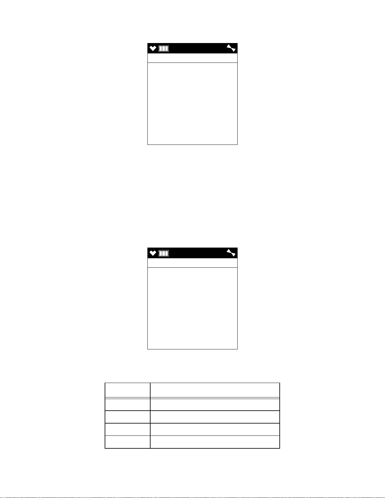
Responding to Clock Failure Alarms
4:07
FAIL CLOCK
4:07
FAIL SYSTEM
0 2 2
A clock failure alarm occurs if the unit’s internal clock malfunctions.
1 . Press and release the RESET button to continue into Measuring Mode.
CAUTION: There will be no datalogging function if you operate the instrument after a
clock failure.
2 . Attempt to change the date using the DATE menu item in Maintenance Mode. See
“Setting the Date and Time (DATE)” on page 137.
3 . If the date cannot be set correctly, contact RKI Instruments, Inc. as soon as possible.
Responding to System Failure Alarms
1 . If a system failure occurs, the system failure screen will display an error code as
shown below:
2 . The error code meanings are shown in the table below:
Table 8: Error Code Explanation
Error Code Explanation
000 ROM failure
010 RAM failure
021 FRAM failure
022 FLASH memory failure
GX-6000 Operator’s Manual Chapter 3: Operation • 45
Page 46

3 . If the error code is anything but 022 as shown above, the instrument cannot be used.
Contact RKI Instruments, Inc. as soon as possible.
If the error code is 022, you may press and release the RESET button to continue into
Measuring Mode if the instrument must be used temporarily.
CAUTION: There will be no datalogging function if you operate the instrument after a
022 system failure. Contact RKI Instruments, Inc. as soon as possible.
Responding to a Man Down Warning 1 and Warning 2
The Man Down Warning 1 and Warning 2 alarms occur after the WARNING 1 TIME and
WARNING 2 TIME, respectively, has passed since the last movement of the instrument.
See “Updating the WARNING 1 TIME Setting” on page 154 and “Updating the
WARNING 2 TIME Setting” on page 154 for instructions to change these values.
1 . Follow your established procedure for a man down warning.
2 . To silence the alarm and reset the Man Down clock, move the instrument or press
and release the RESET button.
Responding to a Man Down Alarm
The Man Down Alarm alarms occur after the ALARM TIME has passed since the last
movement of the instrument. See “Updating the ALARM TIME Setting” on page 154 for
instructions to change this value.
1 . Follow your established procedure for a man down alarm.
2 . To silence the alarm and reset the Man Down clock, press and release the RESET
button. Moving the instrument will not reset the alarm or Man Down clock.
Responding to a Panic Alarm
If the user is in a dangerous situation or feels that others must be alerted to any sort of
problem, holding the SHIFT ▼ (PANIC) button will initiate a panic alarm.
1 . Press and release the RESET button to silence and reset the alarm.
Display Mode
Two other operating modes are accessible when the GX-6000 is in Measuring Mode. They
are Display Mode and Calibration Mode. This section describes using the GX-6000 in
Display Mode. See Table 9 below for a list of Display Mode’s menu items, a short
description of each item, and the page number for further description.
Table 9: Display Mode Items
Menu Item (page number) Description
SELECT PID LIST (pg.48) Define the PID channel’s gas name
PEAK (pg.50) View and clear peak readings
STEL (pg.51) View STEL readings (H
S, CO, and high range PID only)
2
TWA (pg.51) View TWA readings (H
ALARM POINTS (pg.52) View the alarm points
OPERATION TIME (pg.54) View the time in operation
46 • Chapter 3: Operation GX-6000 Operator’s Manual
S, CO, and high range PID only)
2
Page 47
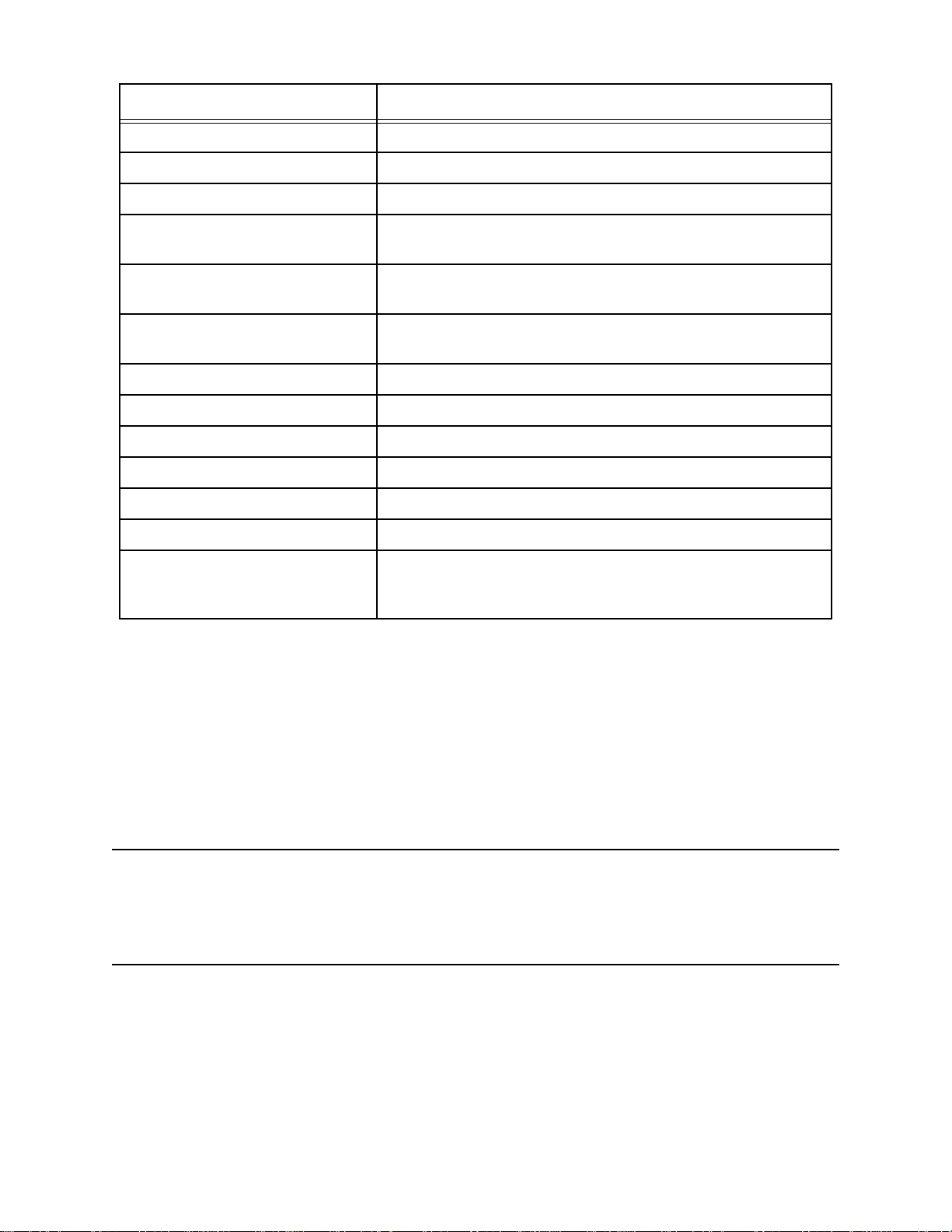
Table 9: Display Mode Items
Menu Item (page number) Description
DATE AND BATTERY (pg.54) View the date/time, battery voltage, and battery type
LOG REMAIN (pg.55) View the log time remaining
LOG CLEAR (pg.55) Clear the log data
PUMP OFF (pg.57) Turn the pump on or off (if the PUMP OFF DISP item in
Maintenance Mode is set to ON)
USER ID (pg.58) Select the user ID (if the ID DISPLAY item in Maintenance
Mode is set to ON)
STATION ID (pg.59) Select the station ID (if the ID DISPLAY item in Maintenance
Mode is set to ON)
REC. DATA DISP (pg.61) View snap logger data
PEAK BAR (pg.62) Turn the peak bar function on or off
GAS DISP (pg.63) Change how the gas readings are displayed
INVERT SELECT (pg.64) Turn the LCD flip function on or off
CAT (LEL) SENSOR (pg.65) Turn the combustible sensor protection on or off
LCD BACKGROUND (pg.66) Reverse the black/white of the LCD
LANGUAGE (pg.66) Change the instrument’s language back to English (only
appears if the language has been changed to something other
than English)
Tips for Using Display Mode
• To enter Display Mode and scroll from one menu item to the next or skip an item when
a question is asked, press and release the DISP/LOCK button.
• To enter an item, press and release the POWER/ENTER button.
• To change a flashing parameter, use either the ▲AIR button or SHIFT ▼ (PANIC)
button.
• To return to Measuring Mode from the top level of any menu item, press and release
the RESET button.
NOTE: With the exception of the Pump Off Screen, each screen displays for 20
seconds. If you do not press a button within 20 seconds, the GX-6000
automatically returns to Measuring Mode. If the Pump Off Screen is used to
turn the instrument’s pump off, the Pump Off Screen will display until you turn
the pump back on.
GX-6000 Operator’s Manual Chapter 3: Operation • 47
Page 48

PID Gas Name Screen
DISP
SELECT PID LIST
PID SET TO
Isobutylene
10.6 eV
CHANGE :ENTER
KEEP :DISP
EXIT :RESET
DISP
SELECT PID 11/24
F -
G -
H -
I-
J -
K -
L -
M -
The standard PID channel is configured for and calibrated to isobutylene. If calibration to
a different gas is required for an application, the PID channel can also be configured for
other gases. Regardless of what gas the PID sensor is configured for and calibrated to, the
sensor will still detect and respond to a variety of volatile organic compounds (VOCs).
If you configure the instrument for another gas, the instrument will retain that
configuration until you change it again. Turning the instrument off and on does not change
this setting.
If there are 2 PID sensors installed in your GX-6000, the PID Gas Name Screens will
appear in Display Mode in the following order regardless of their position in the flow
system: 10.0 eV/benzene, 10.6 eV, 11.7 eV.
1 . With the PID Gas Name Screen displayed, press and release the POWER/ENTER
button. The top level of the PID Gas Name List will be displayed and the cursor will
be next to the letter corresponding to the first letter of the current setting. In the
example below, the PID channel is configured for isobutylene so the cursor is next to
“I”. Each letter has a list of gas names behind it.
At the top of the letter list, there is a User List item and a Recent List item. The User
List can hold 30 gas names. See “Appendix J: Creating a PID User List” on page 240
for instructions to edit the User List. The Recent List can hold up to 8 gas names and
is made up of the 8 most recently used gas names. The Recent List is not user
editable.
48 • Chapter 3: Operation GX-6000 Operator’s Manual
Page 49

2 . Use the ▲AIR and SHIFT ▼ (PANIC) buttons to scroll through the letter and list
DISP
I -
I s o b u t a n o l
I s o b u t y l a c e t a t
I s o b u t y l a c r y l a
I s o b ut y l e n e
I s o b u t y l e n e epo
I s o b u ty r a l d e hy d
I s o b u t y r ic a c i d
I s o d e c a n o l
DISP
I - 17/46
#396 C4H8
VOC RF 1.00
I s o b ut y l e n e
options. To view the gas names behind a letter, User List, or Recent List, press and
release the POWER/ENTER button when the cursor is next to the desired letter.
3 . Use the ▲AIR and SHIFT ▼ (PANIC) buttons to scroll through the gas names.
4 . To view the information for each gas name, press and release the POWER/ENTER
button when the cursor is next to the desired gas name. The number in the upper left
corner is the gas’s number in relation to all other gas names that are stored in the
GX-6000. The chemical formula is displayed next to the gas number. The response
factor relative to isobutylene is listed on the second line. The gas name is listed on
the third line.
5 . To select a gas name, press and release the POWER/ENTER button while you are
viewing the parameters. The selection will be in effect until you change it again.
To return to the gas name list without saving any changes, press and release the
DISP/LOCK button.
6 . To return to the top level PID Gas Name List that has all of the letter choices, press
and release the DISP/LOCK button.
7 . To return to the PID Gas Name Screen, press and release the DISP/LOCK button one
more time.
GX-6000 Operator’s Manual Chapter 3: Operation • 49
Page 50

Peak Screen
PEAK
CH4 O2
%LEL %
H2S CO
ppm ppm
VOC
ppm
10 15.0
13.0 200
2000
PEAK
PEAK CLEAR
HOLD
PEAK
PEAK CLEAR
RELEASE
The peak screen displays the highest (lowest for oxygen) concentrations detected since the
GX-6000 was turned on. Peak readings are stored in the GX-6000’s memory until a higher
level is detected (lower for oxygen), the peak reading is cleared, or the GX-6000 is turned
off.
The lunch break feature enables the GX-6000 to save peak readings when it is turned off
so it can continue them when it is turned on again. See “Turning On the GX-6000” on
page 25.
To clear the peak readings, do the following:
1 . With the Peak Screen displayed, press and hold the RESET button. The following
screen sequence will occur.
2 . Release the RESET button. The peak readings will be reset and the unit will return to
the Peak Screen.
If you do not want to clear the peak readings, release the RESET button before the
above screen sequence occurs. The unit will return to the Peak Screen.
50 • Chapter 3: Operation GX-6000 Operator’s Manual
Page 51

STEL Screen
STEL
H2S CO
ppm ppm
VOC
ppm
2.0 10
10.0
TWA
H2S CO
ppm ppm
VOC
ppm
0.5 5
5.0
The STEL Screen displays the short term exposure limit (STEL) readings for H2S, CO,
and high range VOC only. The STEL reading is the average reading over the last 15
minutes.
TWA Screen
The TWA Screen displays the time weighted average (TWA) readings for H2S, CO, and
high range VOC only.
The TWA reading is the average reading over the last 8 hours. If 8 hours have not elapsed
since the last time the TWA reading was cleared, the average is still calculated over 8
hours. The missing time is assigned a 0 value for readings. If LUNCH BREAK is set to
OFF, the TWA is cleared when the GX-6000 is turned off.
If LUNCH BREAK is set to ON, the GX-6000 will remember TWA readings when it is
turned off so it can continue them when it is turned on again. See “Turning On the GX6000” on page 25.
GX-6000 Operator’s Manual Chapter 3: Operation • 51
Page 52

View Alarm Settings Screen
DISP
ALARM POINTS
YES :ENTER
NO :DISP
EXIT :RESET
The View Alarm Settings Screen gives you the option to view the gas alarm settings for all
active channels.
To view the gas alarm settings, do the following:
1 . With the View Alarm Settings Screen displayed, press and release the POWER/
ENTER button. The Full Scale Settings screen will appear showing full scale settings
for each channel. Use the ▲AIR and SHIFT ▼ (PANIC) buttons to scroll through the
Warning, Alarm, STEL, and TWA settings.
52 • Chapter 3: Operation GX-6000 Operator’s Manual
Page 53

F.S.
CH4 O2
%LEL %
H2S CO
ppm ppm
VOC
ppm
100 40.0
100.0 500
6000
AL1
CH4 O2
%LEL %
H2S CO
ppm ppm
VOC
ppm
10 19.5
5.0 25
400.0
AL2
CH4 O2
%LEL %
H2S CO
ppm ppm
VOC
ppm
50 23.5
30.0 50
1000
STEL
H2S CO
ppm ppm
VOC
ppm
1.0 25
60.0
TWA
H2S CO
ppm ppm
VOC
ppm
5.0 200
40.0
▲ AIR
▲ AIR
▲ AIR
▲ AIR
▲ AIR
SHIFT ▼ (PANIC)
2 . Pressing and releasing the POWER/ENTER button while in a settings screen will
cause the instrument to simulate that condition. The buzzer, LED’s, and vibration
will activate. Press and release the POWER/ENTER button again to stop the
simulated alarm.
3 . Press and release the DISP/LOCK button to return to the View Alarm Settings
Screen.
GX-6000 Operator’s Manual Chapter 3: Operation • 53
Page 54

Time in Operation Screen
DISP
OPERATION TIME
0:02
DISP
DATE AND BATTERY
5/12/2015
MM/DD/YYYY
1:57
4.1V
BATTERY TYPE
ALKALINE
The Time In Operation Screen displays the length of time since the GX-6000 was turned
on if the lunch break feature is turned off. With LUNCH BREAK set to OFF, the time in
operation is reset when the GX-6000 is turned off. See “Updating the Lunch Break Setting
(LUNCH BREAK)” on page 149 for a description of the lunch break feature.
If LUNCH BREAK is set to ON, the time in operation will only be reset if you do not
choose to resume the peak and TWA measurements when the GX-6000 is turned on in the
Lunch Break Screen described in Step 3 on page 26 in “Turning On the GX-6000”. If you
choose to resume the peak and TWA measurements during startup, the GX-6000 will
include the time in operation when the unit was last turned off in the current time in
operation.
Date/Time, Battery Voltage Screen
The Battery Voltage Screen displays the current battery voltage. Fully charged alkaline
batteries typically indicate around 6.0 volts; a fully charged Li-ion battery pack typically
indicate 4.1 volts. This screen also displays during the startup sequence.
54 • Chapter 3: Operation GX-6000 Operator’s Manual
Page 55

Log Time Remaining Screen
DISP
LOG REMAIN
129 HOUR
DISP
LOG CLEAR
YES :ENTER
NO :DISP
EXIT :RESET
The Data Logging screen displays the time remaining until the data logger memory is full.
LOG CLEAR Screen
CAUTION: Once you clear the data logger, you cannot retrieve any data previously
stored in the data logger.
The LOG CLEAR screen asks if you want to clear the data logger memory.
To continue through Display Mode without clearing the log data, press and release the
DISP/LOCK button.
GX-6000 Operator’s Manual Chapter 3: Operation • 55
Page 56

To clear the data logger memory, do the following:
DISP
LOG CLEAR
YES : ENTER
NO : DISP
CONFIRM ?
DISP
LOG CLEAR
CLEAR
1 . With the LOG CLEAR Screen displayed, press and release the POWER/ENTER
button. The following screen appears asking you to confirm that you want to clear
the data logger memory.
2 . If you do not want to clear the data logger memory, press and release the DISP/
LOCK button. The unit will return to the LOG CLEAR screen in Display Mode.
3 . If you want to clear the data logger memory, press and release the POWER/ENTER
button. The unit will display the following screen as it clears the data.
4 . When the instrument has cleared the data, it will return to the LOG CLEAR screen
in Display Mode.
56 • Chapter 3: Operation GX-6000 Operator’s Manual
Page 57

Pump Off Screen
DISP
PUMP OFF
YES :ENTER
NO :DISP
EXIT :RESET
1:44
PUMP OFF
OFF
WARNING: The GX-6000 is not a gas monitoring device while the pump is off.
NOTE: The item appears in Display Mode only if the PUMP OFF DISP menu item in
Maintenance Mode is turned ON. The factory setting for PUMP OFF DISP is
OFF.
This feature can be used to conserve battery life if there is a significant period of time until
the next gas monitoring task, but you do not want to wait for the warm-up sequence to
complete if you turn the instrument off and on again.
1 . In this screen, press and release the POWER/ENTER button to turn the pump off.
The fan symbol in the upper right corner will disappear. Once the pump is off, you
cannot exit this screen and return to Measuring Mode or continue in Display Mode
until you turn the pump back on.
2 . To turn the pump back on and continue in Display Mode or return to Measuring
Mode, press and release the DISP/LOCK button.
GX-6000 Operator’s Manual Chapter 3: Operation • 57
Page 58

Select User ID Screen
DISP
USER ID
KIMBERLY
DISP
USER ID
KIMBERLY
This screen only appears in Display Mode if the ID DISPLAY item in Maintenance Mode
is set to ON. Use this screen to select a user ID from the user ID list in the GX-6000’s
memory. The current user ID is displayed. A user ID can be up to 16 characters long. The
GX-6000 can store up to 128 user IDs.
The user ID provides a way to identify the GX-6000 user during a data logging session. If
the user ID is changed during an operating session, a new data session is initiated with the
new user ID attached to it. This allows you to change the user ID during operation and
have each user ID that was used during an operating session saved for the corresponding
data. See the GX-6000 Data Logger Management Program Operator’s Manual for a
detailed description of data logging and the user ID.
The user ID list cannot be edited using the GX-6000 user interface. The GX-6000
Maintenance Data Loader Program is required to define or change user IDs in the user ID
list. For a detailed description of editing the list of user IDs stored in the GX-6000, see the
GX-6000 Maintenance Data Loader Program Operator’s Manual.
To select a different user ID:
1 . With the Select User ID Screen displayed, press and release the POWER/ENTER
button. The current user ID will be displayed and it will be flashing.
2 . Use the ▲AIR and SHIFT ▼ (PANIC) buttons to scroll through the available user
IDs. The list will wrap around if you get to the top or bottom. Any of the user IDs in
the list that have not been changed from the factory setting will be shown as
USER_ID_XXX where the “XXX” is a number from 001 to 128.
58 • Chapter 3: Operation GX-6000 Operator’s Manual
Page 59

3 . When the desired user ID is displayed, press and release the POWER/ENTER
DISP
STATION ID
TANK 5
button.
NOTE: To exit the selection screen without saving a change, press and release the
DISP/LOCK button. You will return to the Select User ID screen without
saving the user ID change.
4 . The unit will save the selected user ID as the current one and will return you to the
Select User ID Screen.
Select Station ID Screen
This screen only appears in Display Mode if the ID DISPLAY item in Maintenance Mode
is set to ON. Use this screen to select a station ID from the station ID list in the GX-6000’s
memory. The current station ID is displayed. A station ID can be up to 16 characters long.
The GX-6000 can store up to 128 station IDs.
The station ID provides a way to identify a location where monitoring was done during a
data logging session. If the station ID is changed during an operating session, a new data
session is initiated with the new station ID attached to it. This allows you to change the
station ID during operation and have each station ID that was used during an operating
session saved for the corresponding data. See the GX-6000 Data Logger Management
Program Operator’s Manual for a detailed description of data logging and the station ID.
The station ID list cannot be edited using the GX-6000 user interface. The GX-6000
Maintenance Data Loader Program is required to define or change station IDs in the
station ID list. For a detailed description of editing the list of station IDs stored in the
GX-6000, see the GX-6000 Maintenance Data Loader Program Operator’s Manual.
GX-6000 Operator’s Manual Chapter 3: Operation • 59
Page 60

To select a different station ID:
DISP
STATION ID
TANK 5
1 . With the Select Station ID Screen displayed, press and release the POWER/ENTER
button. The current user ID will be displayed and it will be flashing.
2 . Use the ▲AIR and SHIFT ▼ (PANIC) buttons to scroll through the available station
IDs. The list will wrap around if you get to the top or bottom. Any of the station IDs
in the list that have not been changed from the factory setting will be shown as
STATION_ID_XXX where the “XXX” is a number from 001 to 128.
3 . When the desired station ID is displayed, press and release the POWER ENTER
button.
NOTE: To exit the selection screen without saving a change, press and release the
DISP/LOCK button. You will return to the Select Station ID screen without
saving the station ID change.
4 . The unit will save the selected station ID as the current one and return you to the
Select Station ID Screen.
60 • Chapter 3: Operation GX-6000 Operator’s Manual
Page 61

Viewing Snap Logger Data
DISP
REC. DATA DISP
YES :ENTER
NO :DISP
EXIT :RESET
REC DATA
REC. DATA
NO DATA
REC DATA
DATE
5/20/2015
MM/DD/YYYY
3:40
NUMBER 001
TANK 5
No snap logs taken Snap logs taken
The Snap Logging Screen allows you to view data from previous snap logs. For
information on how to use the snap logging feature, see “Snap Log Mode” on page 39.
1 . With the snap logging screen displayed, press and release the POWER/ENTER
button. The screen that appears will depend on whether or not any snap logs have
been taken.
2 . If snap logs have been taken, the screen indicates the year, month, day, and time that
the most recent snap log was taken.
The number near the bottom of the screen indicates the snap log ID number. The first
snap log that is taken is given an ID of 001. The next snap log ID is 002. The ID
number increases sequentially with each set of snap log data.
The last line of the screen indicates the Station ID that was used for the snap log.
3 . Use the ▲AIR and SHIFT ▼ (PANIC)
log IDs.
buttons to scroll through different snap
GX-6000 Operator’s Manual Chapter 3: Operation • 61
Page 62

4 . To view the data in a snap log ID, press and release the POWER/ENTER button.
REC DATA
CH4 O2
%LEL %
H2S CO
ppm ppm
VOC
ppm
0 20.9
0.0 0
0
DISP
PEAK BAR
YES :ENTER
NO :DISP
EXIT :RESET
The gas readings that were taken during the snap log are displayed. You can use the
▲AIR and SHIFT ▼ (PANIC) buttons to scroll through the different snap logs. The
gas readings will change as you view different snap log data but the snap log ID is
not visible from this screen. To scroll through the data by viewing the snap log ID
number, press and release POWER/ENTER.
5 . To return to the Snap Logging Screen, press and release the DISP/LOCK button.
Peak Bar Screen
The Peak Bar Screen allows you to turn the peak bar on or off. If the function is turned on,
the peak bar appears along the right side of each gas reading in Measuring Mode and on
the Peak Screen in Display Mode. It shows the peak readings for each channel in bar graph
format.
1 . With the Peak Bar Screen displayed, press and release the POWER/ENTER button.
The current setting will be displayed.
2 . Use the ▲AIR and SHIFT ▼ (PANIC) buttons to display the desired setting.
3 . Press and release the POWER/ENTER button to save the setting and return to the
Peak Bar Screen.
To return to the Peak Bar Screen without saving any changes, press and release the
DISP/LOCK button.
62 • Chapter 3: Operation GX-6000 Operator’s Manual
Page 63

Gas Display Screen
DISP
GAS DISP
YES :ENTER
NO :DISP
EXIT :RESET
DISP
GAS DISP
DISPLAY ALL
SCROLL AUTO
SCROLL MANUAL
The Gas Display Screen allows the user to choose how the gas readings are displayed in
Measuring Mode. A description of the choices can be found in Table 10 below. If anything
other than DISPLAY ALL is selected, the instrument will return to DISPLAY ALL when
it is turned off and turned back on.
Table 10: Gas Display Choices
Option Description
DISPLAY ALL All active channels’ readings will be displayed at once
SCROLL AUTO One active channel will display at a time and the instrument will
automatically scroll through all active channels for the duration of the
operating session.
SCROLL MANUAL One active channel will display at a time and the user must press and
release the POWER/ENTER button to scroll through all active channels.
If the POWER/ENTER button is not pressed and released, the
instrument will display the same channel’s readings for the duration of
the operating session.
1 . With the Gas Display Screen showing, press and release the POWER/ENTER
button. The available choices will appear.
2 . Use the ▲AIR and SHIFT ▼ (PANIC) buttons to move the cursor next to the desired
setting.
GX-6000 Operator’s Manual Chapter 3: Operation • 63
Page 64

3 . Press and release the POWER/ENTER button to return to the Gas Display Screen.
DISP
INVERT SELECT
YES :ENTER
NO :DISP
EXIT :RESET
To return to the Gas Display Screen without saving any changes, press and release
the DISP/LOCK button.
LCD Flip Screen
If INVERT SELECT is set to ON, the instrument’s LCD will automatically flip if the
instrument is turned upside down. This allows for the LCD to be read with the instrument
right side up or upside down. If desired, holding down the DISP/LOCK button will lock
the screen in its current position and keep it from rotating. A LOCK symbol will flash at
the top of the screen to indicate that the LCD’s position is fixed. To unlock the LCD, hold
the DISP/LOCK button until the LOCK symbol disappears.
NOTE: Even if INVERT SELECT is set to ON, the screens in Calibration Mode, User
Mode, and Maintenance Mode will not flip if the instrument is turned upside
down.
If INVERT SELECT is set to OFF, the instrument’s LCD will not flip and can only be
read when the instrument is right side up. A LOCK symbol will appear at the top of the
screen to indicate that the LCD’s position is fixed.
1 . With the Gas Display Screen showing, press and release the POWER/ENTER
button. The current setting will be displayed.
2 . Use the ▲AIR and SHIFT ▼ (PANIC) buttons to display the desired setting.
3 . Press and release the POWER/ENTER button to return to the LCD Flip Screen.
To return to the LCD Flip Screen without saving any changes, press and release the
DISP/LOCK button.
64 • Chapter 3: Operation GX-6000 Operator’s Manual
Page 65

Combustible Sensor Protection Screen
DISP
CAT (LEL) SENSOR
PROTECTION
DISP
CAT (LEL) SENSOR
***WARNING***
NO LEL ALARMS IF
CAT (LEL) IS
DISABLED
ENABLED
If combustible gas levels greater than 100 %LEL are expected, the catalytic LEL sensor
can be disabled to protect it. If the catalytic LEL sensor is disabled, there will be no %LEL
alarms in Measuring Mode.
1 . With the CAT (LEL) SENSOR PROTECTION screen displayed, press and release
the POWER/ENTER button. The current setting will be displayed along with a
warning about no %LEL alarms if the catalytic LEL sensor is turned off.
2 . Use the ▲AIR or SHIFT ▼ (PANIC) button to display the desired setting.
NOTE: If the catalytic LEL sensor is disabled and if the instrument is then turned off
and back on, the catalytic LEL sensor will be enabled again.
3 . Press and release the POWER/ENTER button to return to the CAT (LEL) SENSOR
PROTECTION screen in Display Mode.
GX-6000 Operator’s Manual Chapter 3: Operation • 65
Page 66

LCD Background Color Flip
DISP
LCD BACKGROUND
YES :ENTER
NO :DISP
EXIT :RESET
DISP
LANGUAGE
CHANGE
TO ENGLISH
YES :ENTER
NO :DISP
EXIT :RESET
With LCD BACKGROUND set to ON, the LCD colors will flip. The background will be
black instead of white and the text will be white instead of black. With LCD
BACKGROUND set to OFF (factory setting), the LCD background will be white and the
LCD text will be black.
1 . With the LCD Background Flip Screen showing, press and release the POWER/
ENTER button. The current setting will be displayed.
2 . Use the ▲AIR and SHIFT ▼ (PANIC) buttons to display the desired setting.
3 . Press and release the POWER/ENTER button to return to the LCD Background Flip
Screen.
To return to the LCD Background Flip Screen without saving any changes, press and
release the DISP/LOCK button.
Language Screen
If the instrument’s language is changed to something other than English, the Language
Screen will appear in Display Mode. The Language Screen will not appear if the
instrument’s language is set to English. The Language Screen allows the user to change
the instrument’s language back to English.
66 • Chapter 3: Operation GX-6000 Operator’s Manual
Page 67

To change the language back to English, do the following:
DISP
LANGUAGE
CHANGE
TO ENGLISH
CONFIRM ?
1 . With the Language Screen showing, press and release the POWER/ENTER button.
The following screen will appear asking you to confirm that you want to change the
language back to English.
2 . Press and release the POWER/ENTER button again to confirm the change.
To return to the Language Screen without changing the instrument’s language to
English, press and release the DISP/LOCK button.
Data Logging
NOTE: The GX-6000 only logs data while in Normal Mode. If the GX-6000 is used in
Leak Check Mode or Bar Hole Mode, no downloadable data will be logged
while it is in either of these two modes.
The GX-6000 features the ability to log data to its internal memory and download it to a
computer via the infrared communications port on the front of the unit. It logs gas readings
in Measuring Mode, alarm data, and calibration data.
NOTE: The data logging function is separate from the snap logging function. For a
description of the snap logging function, see “Snap Log Mode” on page 39.
To utilize the GX-6000’s downloading capability, you will need the GX-6000 Data Logger
Management Program and a computer with an infrared port or a USB port that runs one of
the following operating systems: Windows 7, Windows 8, or Windows 10. If your
computer has an infrared port, then no additional accessories are needed to download data
from the GX-6000. If your computer does not have an infrared port but does have a USB
port, a USB/IrDA adapter cable can be used to download data from the GX-6000 using the
USB port. The GX-6000 Data Logger Management Program is available at
www.rkiinstruments.com/gx6000. The USB/IrDA adapter cable is available from RKI
Instruments, Inc.
The data logging capacity depends on how often the GX-6000 stores data, how many
channels are active, and how often the GX-6000 is turned on and off. The table below
illustrates how much data logging time is available for the various interval times. It
assumes that the unit is a standard four sensors plus PID unit, is only turned on once, and
there are no alarm occurrences. See “Updating the Data Log Interval Setting (LOG
INTERVAL)” on page 155 for instructions on setting the data logging interval time.
GX-6000 Operator’s Manual Chapter 3: Operation • 67
Page 68

Table 11: Data Logging Capacity
Interval
Time
10 seconds 10 hours
20 seconds 20 hours
30 seconds 30 hours
1 minute 60 hours
3 minutes 180 hours
5 minutes 300 hours
10 minutes 600 hours
Data Logging Time
For a complete description of the Data Logger Management Program and procedures for
downloading data to a computer, see the GX-6000 Data Logger Management Program
Operator’s Manual.
68 • Chapter 3: Operation GX-6000 Operator’s Manual
Page 69

Chapter 4: Calibration Mode
Overview
This section describes the GX-6000 in Calibration Mode. In Calibration Mode, you can
move through a menu of screens to do the following:
• Perform a fresh air (zero) adjustment
• Perform a span adjustment on all channels simultaneously using auto calibration
• Perform a span adjustment on one channel at a time using single calibration
• Perform a bump test
NOTE: You can set up the GX-6000 to alert you during the startup sequence when
calibration is due. See “Updating the Calibration Reminder Setting (CAL
REMINDER)” on page 139.
CAUTION: BEFORE EACH DAY’S USAGE, SENSITIVITY IN THE
%LEL RANGE MUST BE TESTED ON A KNOWN CONCENTRATION
OF THE COMBUSTIBLE TARGET GAS, METHANE, EQUIVALENT TO
25 - 50% OF FULL SCALE CONCENTRATION (the %LEL full scale is
100 %LEL). ACCURACY MUST BE WITHIN -0 to + 20% OF ACTUAL.
ACCURACY MAY BE CORRECTED BY FOLLOWING THE
CALIBRATION INSTRUCTIONS FOR THE COMBUSTIBLE CHANNEL
BELOW.
If the combustible channel passes the above response test and does not require calibration,
the unit should still be calibrated periodically. The optimum frequency of calibration
depends heavily on how the GX-6000 is used. For example, instruments used daily may
need to be calibrated weekly or monthly, while instruments that are used only a few times
a year may need to be calibrated before each use. Typical calibration frequencies range
from monthly to quarterly. Make sure to perform the combustible channel response test as
described above and make sure to develop a calibration schedule tailored to your
application that takes this test and required calibration resulting from this test into account.
GX-6000 Operator’s Manual Chapter 4: Calibration Mode • 69
Page 70

Calibration Supplies and Equipment
To calibrate the GX-6000, you will need:
• Known calibrating samples of the gases being detected. The combustible and toxic gas
samples should have concentrations between 10 and 50% of the full scale value. For
example, if you are calibrating the catalytic combustible gas channel, your calibration
cylinder should have a combustible gas concentration between 10% LEL and 50%
LEL. An oxygen-free source, such as 100% nitrogen is recommended for setting the
oxygen zero.
CAUTION: When using auto calibration, although the GX-6000 can be calibrated with
an oxygen concentration of up to 19.5%, RKI Instruments, Inc.
recommends that the multi-gas cylinder have an oxygen concentration in
the range of 10% - 16% oxygen.
• A demand-flow regulator to provide adequate sample gas flow
NOTE: RKI Instruments, Inc. recommends that you dedicate a regulator for use with
chlorine (Cl
gases, particularly hydrogen sulfide (H2S).
• Non-absorbent tubing
) gas and that you do not use that dedicated regulator for any other
2
WARNING: If you are using a calibration kit that includes a gas bag and a fixed
flow regulator or dispensing valve, do not apply gas directly to the
GX-6000 with the regulator or dispensing valve or damage to the pump
will result.
To calibrate the %LEL, oxygen, CO, H
automatically, with no need for a zero-oxygen source, you can use the auto calibration
feature with either a 5-gas cylinder or a 4-gas cylinder and a PID cylinder. This chapter
includes instructions for both scenarios along with instructions for calibrating one channel
at a time using single calibration.
Entering Calibration Mode
To enter Calibration Mode, do the following:
1 . Find a fresh-air environment. This is an environment free of toxic or combustible
gases and of normal oxygen content (20.9%).
2 . While in Measuring Mode, press and hold the SHIFT ▼ (PANIC) button, then press
the DISP/LOCK button and release both buttons.
3 . If the unit prompts you for the password, enter it by using the ▲AIR and SHIFT ▼
(PANIC) buttons to select each password number and then pressing and releasing
POWER/ENTER to enter the number and move on to the next one.
S, and PID sensors at the same time,
2
70 • Chapter 4: Calibra t ion Mode GX-6000 Operator’s Manual
Page 71

NOTE: You will only be prompted to enter a password if the PA SSWORD menu item
CAL
CAL MODE
AIR CAL
AUTO CAL
SINGLE CAL
NORMAL MODE
in User Mode is set to ON. See “Turning the Password Function On or Off” on
page 98 for instructions to update the PASS WOR D setting and to choose a
password.
4 . The Calibration Mode Screen displays with the cursor next to AIR CAL.
NOTE: The following screens illustrate a five-gas GX-6000 for detection of CH4
(%LEL using catalytic sensor), oxygen, H
sensor). Your GX-6000 may display slightly different screens.
S, CO, and VOCs (high range PID
2
Calibrating Using the Auto Calibration Method
This method allows you to calibrate the CH4 (%LEL sensor), oxygen, H2S, CO, and VOC
(PID sensor) sensors simultaneously. It is designed for use with either the RKI 5-gas
calibration cylinder (high range PID only) or an RKI 4-gas cylinder and an RKI PID
cylinder and is the quickest and easiest method to calibrate the GX-6000. See Table 16 on
page 128 for available cylinders. Make sure your calibration cylinder is appropriate for the
PID detection range.
NOTE: The 5-gas calibration cylinder that includes LEL CH4/O2/CO/H2S/isobutylene
is a proprietary gas mix developed by RKI Instruments, Inc. for calibrating a
PID sensor in the presence of the other gases during an auto calibration. It can
also be used for a single calibration of a PID sensor. Do not use a similar gas
mix provided by any other manufacturer when calibrating a PID channel. Use
of a gas mix from another manufacturer that includes isobutylene and these
other gases will result in an inaccurate calibration.
Setting the Fresh Air Reading
1 . Find a fresh-air environment. This is an environment free of toxic or combustible
gases and of normal oxygen content (20.9%).
2 . While in Measuring Mode, press and hold the SHIFT ▼ (PANIC) button, then press
the DISP/LOCK button and release both buttons.
GX-6000 Operator’s Manual Chapter 4: Calibration Mode • 71
Page 72
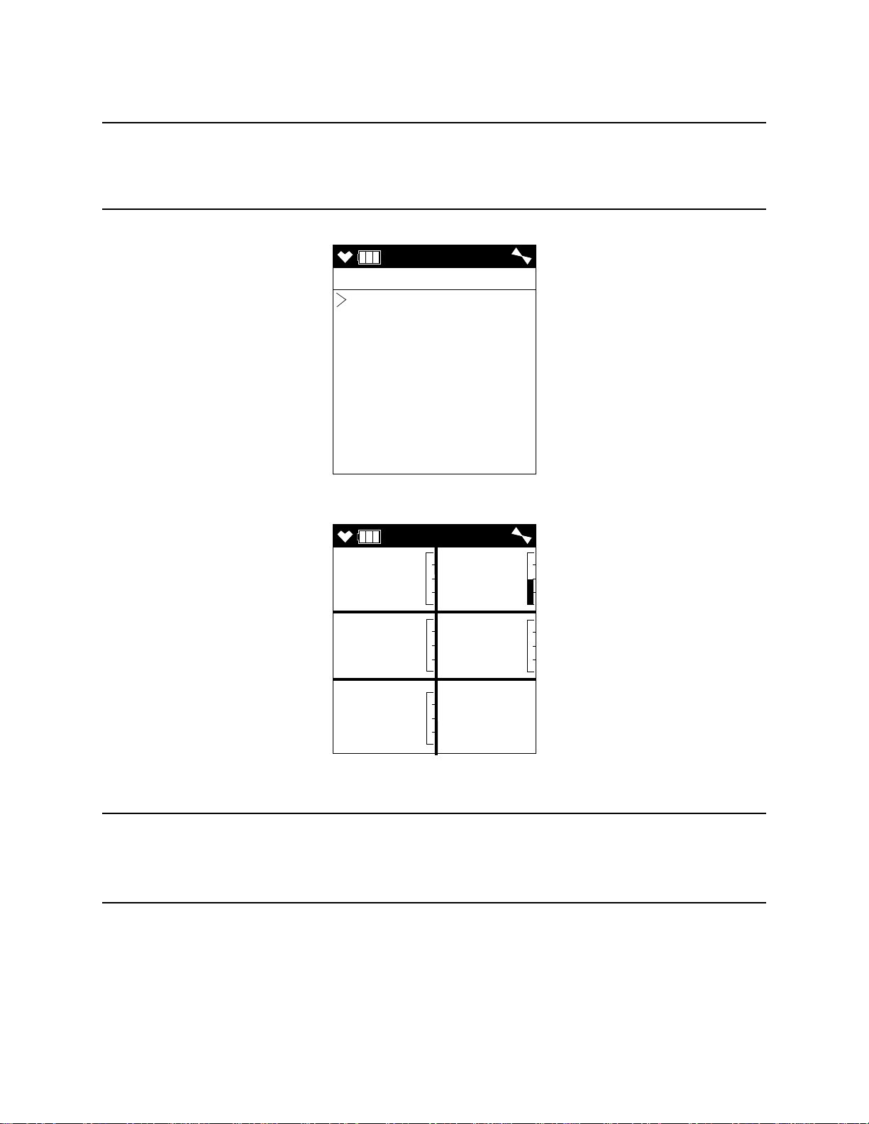
3 . If the unit prompts you for the password, enter it by using the ▲AIR and SHIFT ▼
CAL
CAL MODE
AIR CAL
AUTO CAL
SINGLE CAL
NORMAL MODE
AIR
CH4 O2
%LEL %
H2S CO
ppm ppm
VOC
ppm
0 20.9
0.0 0
0
(PANIC) buttons to select each password number and then pressing and releasing
POWER/ENTER to enter the number and move on to the next one.
NOTE: You will only be prompted to enter a password if the PA SSWORD menu item
in User Mode is set to ON. See “Turning the Password Function On or Off” on
page 98 for instructions to update the PASS WOR D setting and to choose a
password.
4 . The Calibration Mode Screen displays with the cursor next to AIR CAL.
5 . Press and release the POWER/ENTER button. The Fresh Air Reading screen will
display.
6 . If you suspect any low-level VOC background in the area, you will need to use the
VOC zero filter.
NOTE: If you have both a PID and a CO2 sensor installed, you will need to follow the
directions in “Performing a Demand Zero for Instruments with a Carbon
Dioxide Sensor and a PID Sensor” on page 203 instead of following the
directions shown below.
a. Remove the plug from each end of the VOC zero filter.
b. Attach the VOC zero filter to the inlet fitting or probe. The filter does not have a
c. Let the instrument draw through the VOC zero filter for 1 minute before
72 • Chapter 4: Calibra t ion Mode GX-6000 Operator’s Manual
preferred flow direction.
continuing.
Page 73

7 . To continue with the fresh air adjustment, press and hold the ▲AIR button.
AIR
AIR CAL
HOLD AIR KEY
AIR
AIR CAL
HOLD AIR KEY
ADJUSTING ZERO
AIR
AIR CAL
RELEASE AIR KEY
ZERO ADJUSTED
AIR
AIR CAL
ZERO ADJUSTED
CAL
CAL MODE
AIR CAL
AUTO CAL
SINGLE CAL
NORMAL MODE
AIR
AIR CAL
END
AIR
CH4 O2
%LEL %
H2S CO
ppm ppm
VOC
ppm
0 20.9
0.0 0
0
If you do not want to continue, press and release the DISP/LOCK button and the unit
will return to the Calibration Mode Screen.
8 . The GX-6000 will indicate that it is adjusting the zero reading for a few seconds and
then it will prompt you to release the ▲AIR button.
9 . Release the ▲AIR button. The fresh air adjustment will finish, the fresh air readings
will be displayed momentarily, and then the instrument will return to the Calibration
Mode Screen.
GX-6000 Operator’s Manual Chapter 4: Calibration Mode • 73
10 . If the VOC zero filter was used, remove the filter from the GX-6000’s inlet fitting or
probe. Reinstall the plugs on each end of the filter.
Page 74

Performing a Span Adjustment
CAL
CAL MODE
AIR CAL
AUTO CAL
SINGLE CAL
NORMAL MODE
AUTO
AUTO CAL
CONCENTRATION
GAS SELECT
ESCAPE
1 . Install the demand flow regulator onto the 4-gas or 5-gas calibration cylinder.
2 . Connect the sample tubing to the demand flow regulator.
3 . Install the sample hose and probe on the GX-6000 inlet fitting. Make sure the probe’s
two halves are tightened firmly together to avoid leaks that can affect the calibration.
See Figure 22, “Replacing the Particle Filter and Hydrophobic Filter Disk” on
page 110 for an illustration of the internal parts of the probe.
4 . Move the cursor next to the AUTO CAL menu item by using the ▲AIR or SHIFT ▼
(PANIC) button.
5 . Press and release the POWER/ENTER button to display the Auto Cal Menu.
74 • Chapter 4: Calibra t ion Mode GX-6000 Operator’s Manual
Page 75

6 . To check or update the gas concentrations, use the ▲AIR and SHIFT ▼ (PANIC)
AUTO
CONCENTRATION
CH4 50 %LEL
O2 12.0 %
H2S 25.0 ppm
CO 50 ppm
VOC 100 ppm
ESCAPE
buttons to put the cursor next to CONCENTRATION and press and release the
POWER/ENTER button to display the Calibration Gas Values Screen.
The gas concentrations displayed in the Calibration Gas Values Screen must match
the gas concentrations listed on the 5-gas cylinder or the 4-gas calibration cylinder
and the PID cylinder.
If all concentrations match, go to Step 12.
If one or more concentrations do not match, continue with Step 7.
If you do not want to continue with the concentration adjustment, press and release
the DISP/LOCK button to return to the Auto Cal Menu.
NOTE: The RKI 4-gas cylinder typically contains 12% O2 by volume. When using the
auto calibration method, be sure to set the “O2” auto calibration value to agree
with the concentration listed on the cylinder’s label, not zero.
7 . Use the ▲AIR and SHIFT ▼ (PANIC) buttons to place the cursor next to the channel
whose gas value you want to change.
8 . Press and release the POWER/ENTER button. The auto cal value will begin to flash.
9 . Use the ▲AIR and SHIFT ▼ (PANIC) buttons to adjust the calibration gas setting to
the desired value.
NOTE: The calibration gas value cannot be set lower than the low alarm setting. If the
calibration gas value listed on the calibration cylinder is lower than the current
low alarm setting, enter Maintenance Mode and change the low alarm setting.
See “Updating the Alarm Point Settings (ALARM POINTS)” on page 145 for
instructions. If you need to change the alarm point setting only to perform a
calibration, make sure that you change the alarm point setting back to its
original value once the calibration has been performed.
10 . Press and release the POWER/ENTER button to save the change. The calibration gas
value stops flashing.
11 . Repeat Step 7 through Step 10 for any other channels that need to be changed.
GX-6000 Operator’s Manual Chapter 4: Calibration Mode • 75
Page 76

12 . When you are done adjusting the calibration gas values, move the cursor to
AUTO
CONCENTRATION
CH4 50 %LEL
O2 12.0 %
H2S 25.0 ppm
CO 50 ppm
VOC 100 ppm
ESCAPE
AUTO
AUTO CAL
CONCENTRATION
GAS SELECT
ESCAPE
ESCAPE.
13 . Press and release the POWER/ENTER button. The instrument returns to the Auto
Cal Menu.
14 . Use the ▲AIR and SHIFT ▼ (PANIC) buttons to move the cursor next to GAS
SELECT.
76 • Chapter 4: Calibra t ion Mode GX-6000 Operator’s Manual
Page 77

15 . Press and release the POWER/ENTER button. The first of the Gas Select Screens,
AUTO
GAS SELECT
CH4 50 %LEL
O2 12.0 %
H2S 25.0 ppm
CO 50 ppm
AUTO
GAS SELECT
VOC 100 ppm
AUTO
GAS SELECT
ESCAPE
▲ AIR or
SHIFT ▼ (PANIC)
▲ AIR or
SHIFT ▼ (PANIC)
▲ AIR or
SHIFT ▼ (PANIC)
APPLYGAS
CH4 O2
%LEL %
H2S CO
ppm ppm
0 20.9
0.0 0
the standard four sensors screen, will be displayed. In addition to the standard four
sensors screen, there is a separate screen for each installed smart sensor, and an
ESCAPE screen that will take you back to the Auto Cal menu. Use the ▲AIR and
SHIFT ▼ (PANIC) buttons to scroll through the different screens.
16 . With the standard four sensors screen displayed, press and release the POWER/
ENTER button to proceed to the Calibration In Process Screen with APPLYGAS
and the gas readings flashing.
GX-6000 Operator’s Manual Chapter 4: Calibration Mode • 77
If you do not want to proceed with the calibration, press and release the DISP/LOCK
button to return to the Gas Select Screen.
If you do want to continue with the calibration, proceed to the next step.
Page 78

17 . Connect the tubing from the demand flow regulator to the rigid tube on the probe.
AUTO
PASS
AUTO
AUTO CAL
CONCENTRATION
GAS SELECT
ESCAPE
4:07
CH4 O2
%LEL %
H2S CO
ppm ppm
50 12.0
25.0 50
SENSOR
O2
%
H2S
ppm
FAIL
FAIL
Allow the GX-6000 to draw gas for one minute.
18 . Press and release the POWER/ENTER button to set the span adjustment for each
channel to the programmed values.
19 . If all channels passed calibration, the following screen sequence occurs.
20 . If any of the sensors cannot be adjusted to the proper value, a screen displays that
indicates a calibration failure and lists the sensor(s) that failed to calibrate. In the
example below, the oxygen and H2S channels failed calibration. The other sensors
calibrated normally.
78 • Chapter 4: Calibra t ion Mode GX-6000 Operator’s Manual
The buzzer and alarm LEDs activate in a double pulsing pattern. Press and release
the RESET button to reset the alarm and continue to the Auto Cal Menu. After
calibrating the PID channel by following the instructions below, attempt to calibrate
the standard channels again. If the failure continues, investigate the cause. See
“Troubleshooting” on page 100.
21 . If you were using a 5-gas calibration cylinder, continue to Step 22.
If you were using a 4-gas calibration cylinder:
a. Remove the tubing from the rigid tube on the probe.
b. Unscrew the 4-gas cylinder from the regulator.
c. Screw the PID calibration cylinder onto the demand flow regulator. Continue
with Step 23.
Page 79

22 . If you are using a 5-gas calibration cylinder:
AUTO
AUTO CAL
CONCENTRATION
GAS SELECT
ESCAPE
AUTO
GAS SELECT
CH4 50 %LEL
O2 12.0 %
H2S 25.0 ppm
CO 50 ppm
AUTO
GAS SELECT
VOC 100 ppm
AUTO
GAS SELECT
ESCAPE
▲ AIR or
SHIFT ▼ (PANIC)
▲ AIR or
SHIFT ▼ (PANIC)
▲ AIR or
SHIFT ▼ (PANIC)
a. Leave the tubing connected to the rigid tube on the probe. Continue with Step 23.
23 . Use the ▲AIR and SHIFT ▼ (PANIC) buttons to move the cursor next to GAS
SELECT.
24 . Press and release the POWER/ENTER button. The first of the Gas Select Screens,
the standard four sensors screen, will be displayed. In addition to the standard four
sensors screen, there is a separate screen for each installed smart sensor, and an
ESCAPE screen that will take you back to the Auto Cal menu. Use the ▲AIR and
SHIFT ▼ (PANIC) buttons to scroll through the different screens.
GX-6000 Operator’s Manual Chapter 4: Calibration Mode • 79
Page 80

25 . With the VOC channel’s Gas Select Screen displayed, press and release the POWER/
AUTO
GAS SELECT
Isobutylene
Acetone
ESCAPE
APPLYGAS
VOC
ppm
0
ENTER button. The target gas selection screen will display. This screen allows you
to select the gas you want to use for calibration. Isobutylene will always be displayed
on the top line. The second line will show the gas that is currently selected in the PID
Gas Name Screen in Display Mode. In the example below, acetone is the currently
selected gas. If isobutylene is the selected gas, then isobutylene will appear twice in
this list.
26 . Use the ▲AIR and SHIFT ▼ (PANIC) buttons to move the cursor next to the gas you
want to use for calibration.
27 . Press and release the POWER/ENTER button to proceed to the Calibration In
Process Screen for the PID channel with APPLYGAS and the gas reading flashing.
If you do not want to proceed with the calibration, press and release the DISP/LOCK
button to return to the Gas Select Screen.
If you do want to continue with the calibration, proceed to the next step.
28 . If you are using a 5-gas calibration cylinder, continue with Step 29.
If you are using a PID only calibration cylinder:
a. Connect the tubing from the regulator to the rigid tube on the probe. Allow the
GX-6000 to draw gas for one minute.
b. Press and release the POWER/ENTER button to set the span adjustment for the
PID channel to the programmed value. Continue with Step 30.
80 • Chapter 4: Calibra t ion Mode GX-6000 Operator’s Manual
Page 81

29 . If you are using a 5-gas calibration cylinder:
AUTO
END
4:07
VOC
ppm
100
AUTO
AUTO CAL
CONCENTRATION
GAS SELECT
ESCAPE
SENSOR
VOC
ppm
FAIL
a. Since calibration gas has already been flowing to the PID sensor while the other
channels were being calibrated, the PID sensor reading should be stable and
ready for adjustment.
b. Press and release the POWER/ENTER button to set the span adjustment for the
PID channel to the programmed value. Continue with Step 30.
30 . If the PID channel passed calibration, the following screen sequence occurs.
If the PID channel cannot be adjusted to the proper value, a screen displays that
indicates a calibration failure and indicates that the PID sensor failed to calibrate.
GX-6000 Operator’s Manual Chapter 4: Calibration Mode • 81
The buzzer and alarm LEDs activate in a double pulsing pattern. Press and release
the RESET button to reset the alarm and continue to the Auto Cal Menu. Attempt to
calibrate the PID channel again. If the failure continues, investigate the cause. See
“Troubleshooting” on page 100.
Returning to Measuring Mode
1 . Disconnect the tubing from the probe.
2 . Unscrew the demand flow regulator from the calibration cylinder.
3 . Use the SHIFT ▼ (PANIC) button to move the cursor next to ESCAPE, then press
and release the POWER/ENTER button to return to the Calibration Mode Menu.
4 . Use the SHIFT ▼ (PANIC) button to place the cursor next to the NORMAL MODE
menu option, then press and release the POWER/ENTER button to return to
Measuring Mode.
Page 82

Calibrating Using the Single
CAL
CAL MODE
AIR CAL
AUTO CAL
SINGLE CAL
NORMAL MODE
AIR
CH4 O2
%LEL %
H2S CO
ppm ppm
VOC
ppm
0 20.9
0.0 0
0
Calibration Method
Single Calibration allows you to calibrate one channel at a time. This is useful if you only
want to calibrate one or two channels.
Setting the Fresh Air Reading
1 . While in the Calibration Mode Screen, move the cursor to the AIR CAL menu item
by using the SHIFT ▼ (PANIC) button.
2 . Press and release the POWER/ENTER button. The Fresh Air Reading Screen will be
displayed.
3 . If you suspect any low-level VOC background in the area, you will need to use the
VOC zero filter.
NOTE: If you have both a PID and a CO2 sensor installed, you will need to follow the
directions in “Performing a Demand Zero for Instruments with a Carbon
Dioxide Sensor and a PID Sensor” on page 203 instead of following the
directions shown below.
a. Remove the plug from each end of the VOC zero filter.
b. Attach the VOC zero filter to the inlet fitting or probe. The filter does not have a
preferred flow direction.
82 • Chapter 4: Calibra t ion Mode GX-6000 Operator’s Manual
Page 83

c. Let the instrument draw through the VOC zero filter for 1 minute before
AIR
AIR CAL
HOLD AIR KEY
AIR
AIR CAL
HOLD AIR KEY
ADJUSTING ZERO
AIR
AIR CAL
RELEASE AIR KEY
ZERO ADJUSTED
AIR
AIR CAL
ZERO ADJUSTED
AIR
CH4 O2
%LEL %
H2S CO
ppm ppm
VOC
ppm
0 20.9
0.0 0
0
CAL
CAL MODE
AIR CAL
AUTO CAL
SINGLE CAL
NORMAL MODE
continuing.
4 . To continue with the fresh air adjustment, press and hold the ▲AIR button.
If you do not want to continue, press and release the DISP/LOCK button and the unit
will return to the Calibration Mode Screen.
5 . The GX-6000 will indicate that it is adjusting the zero reading for a few seconds and
then it will prompt you to release the ▲AIR button.
6 . Release the ▲AIR button. The fresh air adjustment will finish, the fresh air readings
will be displayed momentarily, and then the instrument will return to the Calibration
Mode Screen.
7 . If the VOC zero filter was used, remove the filter from the GX-6000’s inlet fitting or
probe. Reinstall the plugs on each end of the filter.
Performing a Span Adjustment in Single Calibration
1 . Install the demand flow regulator onto the calibration cylinder.
2 . Connect the sample tubing to the demand flow regulator.
3 . Install the sample hose and probe on the GX-6000 inlet fitting. Make sure the probe’s
two halves are tightened firmly together to avoid leaks that can affect the calibration.
See Figure 22, “Replacing the Particle Filter and Hydrophobic Filter Disk” on
page 110 for an illustration of the internal parts of the probe.
GX-6000 Operator’s Manual Chapter 4: Calibration Mode • 83
Page 84

4 . Move the cursor next to the SINGLE CAL menu item by using the ▲AIR or SHIFT
CAL
CAL MODE
AIR CAL
AUTO CAL
SINGLE CAL
NORMAL MODE
SINGLE
SINGLE CAL
CH4
O2
H2S
CO
VOC
ESCAPE
▼ (PANIC) button.
5 . Press and release the POWER/ENTER button. The Select Sensor Screen appears.
6 . Move the cursor next to the sensor you want to calibrate with the ▲AIR and SHIFT
▼ (PANIC) buttons. In the example above, the CH
adjustment.
If you do not want to proceed with the span adjustment, press and release the DISP/
LOCK button or place the cursor next to ESCAPE and press and release POWER/
ENTER to return to the Calibration Mode Screen.
To proceed with the calibration, continue with the next step.
7 . For a CH
For a VOC channel, see Step 8 and Step 9 before continuing with Step 10.
, O2, H2S, or CO channel continue to Step 10.
4
sensor is selected for span
4
84 • Chapter 4: Calibra t ion Mode GX-6000 Operator’s Manual
Page 85

8 . Press and release the POWER/ENTER button. The target gas selection screen will
SINGLE
GAS SELECT
Isobutylene
Acetone
ESCAPE
APPLYGAS
CH4
%LEL
0
display. This screen allows you to select the gas you want to use for calibration.
Isobutylene will always be displayed on the top line. The second line will show the
gas that is currently selected in the PID Gas Name Screen in Display Mode. In the
example below, acetone is the currently selected gas. If isobutylene is the selected
gas, then isobutylene will appear twice in this list.
9 . Use the ▲AIR and SHIFT ▼ (PANIC) buttons to move the cursor next to the gas you
want to use for calibration. Continue to Step 10.
10 . Press and release the POWER/ENTER button to proceed to the Single Calibration
Apply Gas Screen. APPLYGAS and the gas reading will be flashing.
The screen shown below is for the CH4 channel. If you are calibrating a different
channel, your screen will look slightly different.
11 . Connect the tubing from the demand flow regulator to the rigid tube on the probe.
Allow the GX-6000 to draw gas for one minute.
12 . If necessary, adjust the reading to match the cylinder concentration with the ▲AIR
and SHIFT ▼ (PANIC) buttons. If the reading cannot be adjusted to match the
cylinder concentration, see “Troubleshooting” on page 100.
GX-6000 Operator’s Manual Chapter 4: Calibration Mode • 85
Page 86

13 . Press and release the POWER/ENTER button to save the span value. The LCD will
SINGLE
PASS
SINGLE
SINGLE CAL
CH4
O2
H2S
CO
VOC
ESCAPE
SINGLE
SINGLE CAL
CH4
O2
H2S
CO
VOC
ESCAPE
indicate that the calibration has ended, then the Select Sensor Screen appears.
14 . Disconnect the tubing from the GX-6000’s probe.
15 . Repeat Step 6 through Step 14 for any other channels you want to calibrate. Make
sure you use an appropriate calibration cylinder for each sensor.
CAUTION: When calibrating the oxygen sensor, verify the concentration of oxygen
listed on the cylinder’s label. For oxygen-free samples (100% nitrogen for
example), set the oxygen calibration value to 0.0%.
16 . After the last channel is calibrated, disconnect the calibration tubing from the probe,
then unscrew the demand flow regulator from the calibration cylinder.
17 . With the Select Sensor Screen displayed, place the cursor next to ESCAPE using the
▲AIR or SHIFT ▼ (PANIC) button.
18 . Press and release the POWER/ENTER button to return to the Calibration Mode
Screen.
19 . Use the SHIFT ▼ (PANIC) button to place the cursor next to the NORMAL MODE
menu item, then press and release the POWER/ENTER button to return to
Measuring Mode.
86 • Chapter 4: Calibra t ion Mode GX-6000 Operator’s Manual
Page 87

Performing a Bump Test
CAL
CAL MODE
AIR CAL
AUTO CAL
SINGLE CAL
BUMP TEST
NORMAL MODE
NOTE: The BUMP DISP menu item in Maintenance Mode is factory set to OFF. The
BUMP TEST menu item will not appear unless BUMP DISP is set to ON. See
“Updating the Bump Display Setting (BUMP DISP)” on page 141 for
instructions.
NOTE: The GX-6000 uses parameters defined in the BUMP PARAMETERS menu
item of Maintenance Mode while performing a bump test. To view or update
these parameters, see “Updating the Bump Parameters (BUMP
PARAMETERS)” on page 142.
If the combustible gas channel is calibrated to a gas other than methane, use an appropriate
multigas cylinder.
1 . Install the demand flow regulator onto the calibration cylinder.
2 . Connect the sample tubing to the demand flow regulator.
3 . Install the sample hose and probe on the GX-6000 inlet fitting. Make sure the probe’s
two halves are tightened firmly together to avoid leaks that can affect the calibration.
See Figure 22, “Replacing the Particle Filter and Hydrophobic Filter Disk” on
page 110 for an illustration of the internal parts of the probe.
4 . While in Measuring Mode, press and hold the SHIFT ▼ (PANIC) button, then press
the DISP/LOCK button and release both buttons.
5 . If the unit prompts you for the password, enter it by using the ▲AIR and SHIFT ▼
(PANIC) buttons to select each password number and then pressing and releasing
POWER/ENTER to enter the number and move on to the next one.
NOTE: You will only be prompted to enter a password if the PA SSWORD menu item
in User Mode is set to ON. See “Turning the Password Function On or Off” on
page 98 for instructions to update the PASS WOR D setting and to choose a
password.
6 . The Calibration Mode Screen displays with the cursor next to AIR CAL.
GX-6000 Operator’s Manual Chapter 4: Calibration Mode • 87
Page 88

7 . Move the cursor next to the BUMP TEST menu item by using the SHIFT ▼
CAL
CAL MODE
AIR CAL
AUTO CAL
SINGLE CAL
BUMP TEST
NORMAL MODE
AUTO
GAS SELECT
CH4 50 %LEL
O2 12.0 %
H2S 25.0 ppm
CO 50 ppm
AUTO
GAS SELECT
VOC 100 ppm
AUTO
GAS SELECT
ESCAPE
▲ AIR or
SHIFT ▼ (PANIC)
▲ AIR or
SHIFT ▼ (PANIC)
▲ AIR or
SHIFT ▼ (PANIC)
(PANIC) button.
8 . Press and release the POWER/ENTER button. The first of the Gas Select Screens,
the standard four sensors screen, will be displayed. In addition to the standard four
sensors screen, there is a separate screen for each installed smart sensor, and an
ESCAPE screen that will take you back to the Calibration Mode menu. Use the
▲AIR and SHIFT ▼ (PANIC) buttons to display the gas(es) you want to test.
9 . Before proceeding, confirm that the bump test gas value(s) are the same as the
concentration(s) in the calibration cylinder. If they are not, adjust the bump test gas
88 • Chapter 4: Calibra t ion Mode GX-6000 Operator’s Manual
value(s) be entering the AUTO CAL menu item in Calibration Mode, changing the
value(s) there, and reentering the BUMP TEST menu item.
Page 89

10 . With the desired sensor screen displayed, connect the tubing from the demand flow
30BUMP
CH4 O2
%LEL %
H2S CO
ppm ppm
0 20.9
0.0 0
BUMP
CH4 OK
O2 NG
H2S OK
CO NG
BUMP
CH4 O2
%LEL %
H2S CO
ppm ppm
50 19.0
25.0 13
▲ AIR or
SHIFT ▼ (PANIC)
regulator to the rigid tube on the probe then quickly press and release the POWER/
ENTER button to proceed to the Bump In Progress Screen. The instrument will
count down.
If you do not want to proceed with the bump test, press and release the DISP/LOCK
button to return to the Gas Select Screen.
If you do want to continue with the bump test, proceed to the next step.
11 . When AUTO CAL in the BUMP PARAMETERS menu item in Maintenance
Mode is set to OFF:
a. The instrument will indicate which channels passed or failed the bump test with
an OK (pass) or an NG (fail) to the right of the gas. You can scroll between the
bump test results and the bump test gas readings with the ▲AIR and SHIFT ▼
(PANIC) button.
b. To return to the Gas Select Screen, press and release the POWER/ENTER button.
If any channel failed the bump test, the buzzer will sound a double pulsing tone
until you press and release the POWER/ENTER button.
If one or more sensors fail the bump test, see “Troubleshooting” on page 100 to
investigate the cause of the failure and replace the failed sensor or sensors if
GX-6000 Operator’s Manual Chapter 4: Calibration Mode • 89
necessary.
c. Disconnect the tubing from the probe.
Page 90

12 . When AUTO CAL in the BUMP PARAMETERS menu item in Maintenance
BUMP
CH4 OK
O2 OK
H2S OK
CO OK
BUMP
CH4 O2
%LEL %
H2S CO
ppm ppm
50 12.0
25.0 50
▲ AIR or
SHIFT ▼ (PANIC)
60CAL
CH4 O2
%LEL %
H2S CO
ppm ppm
49 19.0
23.0 32
Mode is set to ON:
If all channels pass the bump test:
a. The results screen appears. You can scroll between the bump test results and the
bump test gas readings with the ▲AIR and SHIFT ▼ (PANIC) buttons.
b. To return to the Gas Select Screen, press and release the POWER/ENTER button.
c. Disconnect the tubing from the probe.
If any channel fails the bump test:
a. The instrument will beep and a calibration is immediately and automatically
started. Continue to apply the calibration gas. CAL will appear at the top of the
screen along with a countdown.
The calibration time counted down during a calibration initiated because of a
failed bump test is the difference between the gas time and the calibration time
defined in the BUMP SETTING menu item in Maintenance Mode.
90 • Chapter 4: Calibra t ion Mode GX-6000 Operator’s Manual
Page 91

b. At the end of the calibration, the instrument displays the results from both the
BUMP
CH4 OK OK
O2 NG NG
H2S OK OK
CO NG OK
CAL
CH4 O2
%LEL %
H2S CO
ppm ppm
50 18.0
25.0 49
BUMP
CH4 O2
%LEL %
H2S CO
ppm ppm
49 19.0
23.0 32
▲ AIR or
▲ AIR or
▲ AIR or
SHIFT ▼ (PANIC)
SHIFT ▼ (PANIC)
SHIFT ▼ (PANIC)
bump test and the calibration. Use the ▲AIR and SHIFT ▼ (PANIC) button to
scroll between the calibration/bump test results, the bump test gas readings, and
the calibration gas readings.
c. To return to the Gas Select Screen, press and release the POWER/ENTER button
GX-6000 Operator’s Manual Chapter 4: Calibration Mode • 91
d. Disconnect the tubing from the probe.
13 . Unscrew the demand flow regulator from the calibration cylinder.
14 . If you want to bump test any more channels, repeat Step 13 - Step 13.
15 . Use the SHIFT ▼ (PANIC) button to display the ESCAPE screen, then press and
16 . Use the SHIFT ▼ (PANIC) button to place the cursor next to the NORMAL MODE
at any time. If any channel failed the calibration, the buzzer will sound a double
pulsing tone until you press and release the POWER/ENTER button.
release the POWER/ENTER button to return to the Calibration Mode Menu.
menu option, then press and release the POWER/ENTER button to return to
Measuring Mode.
Page 92

Chapter 5: User Mode
Overview
This section describes the GX-6000 in User Mode. See Table 12 below for a list of the
items found in User Mode, the page that the menu item’s instructions can be found on, and
a short description of the menu item.
Table 12: User Mode Menu Items
Menu Item (page number) Description
DATE (pg.94) Set the instrument’s date and time
DATE FORMAT (pg.94) Set the date format
CONFIGURE CH (pg.95) Change sensor/channel assignment
LANGUAGE (pg.97) Change the instrument’s language
ROM/SUM (pg.97) View the instrument’s ROM number and checksum
PASSWORD (pg.98) Turn the User Mode password function on or off and
update the password
START MEASURE (pg.99) Return to Measuring Mode
Tips for Using User Mode
• When in the main menu, the cursor (>) indicates which menu item will be selected if
the POWER/ENTER button is pressed and released.
• Use the SHIFT ▼ (PANIC) button to move the cursor down through the main menu
and submenu items, and to lower values or change the setting in a specific option.
• Use the ▲AIR button to move the cursor up through the main menu and submenu
items, and to raise values or change the setting in a specific option.
• Use the POWER/ENTER button to enter a selected menu item with the cursor next to
it and to enter and save settings during programming.
• An adjustable parameter that is flashing can be adjusted with the ▲AIR and SHIFT ▼
(PANIC) buttons.
• Press the DISP/LOCK button while in a screen where you are entering or updating
parameters to exit the screen without saving any changes.
Entering User Mode
WARNING: The GX-6000 is not in operation as a gas detector while in User Mode.
1 . Take the GX-6000 to a non-hazardous location and turn it off if it is on.
2 . Press and hold the ▲AIR and SHIFT ▼ (PANIC) buttons, then press and hold the
POWER/ENTER button. When you hear a beep, release the buttons.
92 • Chapter 5: User M ode GX-6000 Operator’s Manual
Page 93

3 . The screen that appears will depend on the setting of User Mode’s PASSWORD
PASSWORD
MODE SELECT
USER MODE
MAINTENANCE
PASSWORD
INPUT
PASSWORD
0 0 0 0
PASSWORD set to OFF PASSWORD set to ON
MAINTE
USER
DATE
DATE FORMAT
CONFIGURE CH
LANGUAGE
ROM/SUM
PASSWORD
START MEASURE
item.
If PASSWO RD is set to OFF (factory setting), continue with Step 4.
If PASSWO RD is set to ON, continue with Step 6.
4 . If PASS WORD has been set to OFF, the Mode Select screen will appear, prompting
you to choose the mode you’d like to enter.
5 . Use the ▲AIR and SHIFT ▼ (PANIC) buttons to put the cursor in front of USER
MODE and press and release the POWER/ENTER button. Continue to Step 8.
6 . If PA SSWORD has been set to ON in User Mode, a password screen will appear.
The first digit will be flashing.
7 . Enter the password by using the ▲AIR and SHIFT ▼ (PANIC) buttons to select each
password number and then pressing and releasing the POWER/ENTER button to
enter it and move on to the next number until all of the numbers are entered.
Continue to Step 8.
8 . The main menu displays. It has 7 menu items.
9 . Use the ▲AIR or SHIFT ▼ (PANIC) button to move the cursor up and down the
menu items.
GX-6000 Operator’s Manual Chapter 5: User Mode • 93
Page 94
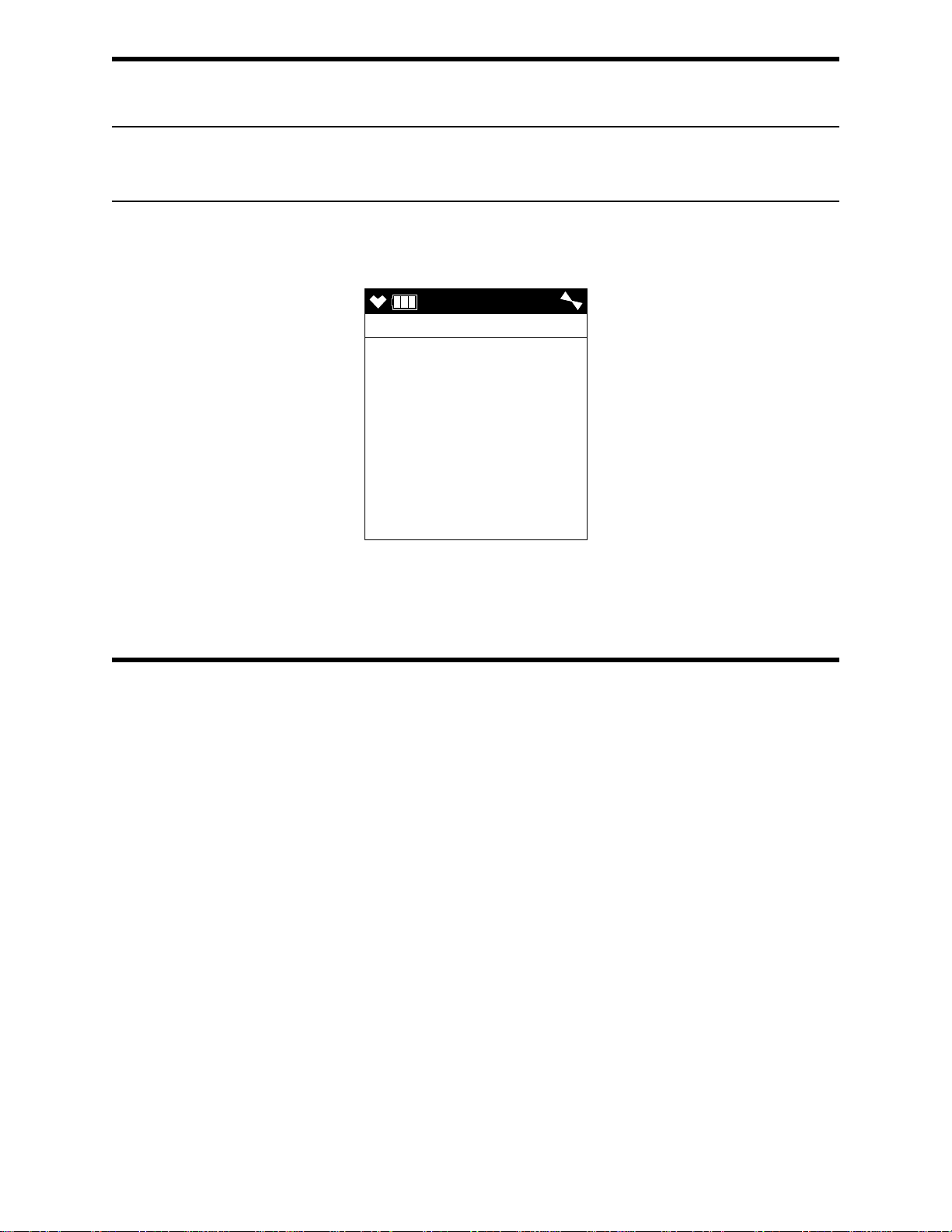
Setting the Date and Time
DATE
DATE
5/ 1/2015
MM/DD/YYYY
12:55
NOTE: The example screen shown below assumes a DATE FORMAT setting of MM/
DD/YYYY (factory setting). If your instrument’s DATE FORMAT is set to
something else, your screen will appear different.
1 . From the main menu, place the cursor next to DATE.
2 . Press and release POWER/ENTER. The date and time will be displayed with the
year flashing.
3 . Use ▲AIR or SHIFT ▼ (PANIC) to display the desired year.
4 . Press and release POWER/ENTER to save the setting. The month setting flashes.
5 . Repeat Step 3 and Step 4 to enter the month, day, hours, and minutes settings. The
main menu displays after you enter the seconds setting.
Setting the Date Format
The date can be displayed in three ways, MM/DD/YYYY (factory setting), DD/MM/
YYYY, or YYYY/MM/DD.
1 . From the main menu, place the cursor next to DATE FORMAT.
2 . Press and release POWER/ENTER. The Date Format screen appears with the current
setting flashing.
3 . Use ▲AIR or SHIFT ▼ (PANIC) to display the desired setting.
4 . Press and release POWER/ENTER to save the setting and return to the main menu.
94 • Chapter 5: User M ode GX-6000 Operator’s Manual
Page 95

Configuring the Channels
USER
CONFIGURE CH
CH 1 : CH4 (HC )
CH 2 : O2 (OX )
CH 3 : H2S (H2S )
CH 4 : CO (CO )
CH 5 : VOC (SM1)
ESCAPE
USER
CHANNEL 1
CH4 (HC )
O2 (OX )
H2S (H2S )
CO (CO )
VOC (SM1)
ESCAPE
The CONFIGURE CH menu item allows you to rearrange the display order of the active
channels.
1 . From the main menu, place the cursor next to CONFIGURE CH.
2 . Press and release POWER/ENTER. The Configure Channels screen appears with the
cursor next to CH1.
3 . Use ▲AIR or SHIFT ▼ (PANIC) to move the cursor next to the channel you want to
configure.
4 . Press and release POWER/ENTER. The available configuration options are shown.
The current setting for the channel will be flashing.
GX-6000 Operator’s Manual Chapter 5: User Mode • 95
Page 96

5 . Use ▲AIR and SHIFT ▼ (PANIC) to move the cursor next to the desired
USER
CHANNEL 1
CH4 (HC )
O2 (OX )
H2S (H2S )
CO (CO )
VOC (SM1)
ESCAPE
configuration for the selected channel. In the example below, the cursor has been
moved next to the H2S (H2S ) selection.
6 . Press and release POWER/ENTER to select the channel configuration.
NOTE: Each channel must have a gas assignment. If you change one channel’s gas to
something else, the two affected channels will end up swapping places. In the
example above, when you select H2S as channel 1’s new gas, CH4, which used
to be channel 1, would automatically be assigned to channel 3, H2S’ old
channel.
7 . Repeat Step 5 and Step 6 for any other channels you want to configure.
8 . Use SHIFT ▼ (PANIC) to move the cursor next to the ESCAPE menu item.
NOTE: If you want to exit to the main menu without saving any channel configuration
changes, press and release DISP/LOCK.
9 . Press and release POWER/ENTER to save the changes and return to the main menu.
96 • Chapter 5: User M ode GX-6000 Operator’s Manual
Page 97

Updating the Language Setting
USER
LANGUAGE
ENGLISH
JAPANESE
ITALIAN
SPANISH
GERMAN
FRENCH
PORTUGUESE
RUSSIAN
ROM/SUM
ROM 05017
SUM 62C7
The LANGUAGE menu item allows you to select the language for the GX-6000’s user
interface. The available choices are English (factory setting), Japanese, Italian, Spanish,
German, French, Portuguese, Russian, and Korean.
1 . From the main menu, place the cursor next to LANGUAGE.
2 . Press and release POWER/ENTER. The Select Language Screen appears with the
cursor in front of the current language.
3 . Use ▲AIR or SHIFT ▼ (PANIC) to move the cursor in front of the desired language.
If you do not wish to select a new language, press and release DISP/LOCK. The unit
will return to the main menu.
4 . Press and release POWER/ENTER to save the new language setting and return to the
main menu. The GX-6000’s user interface will now be in the newly selected
language.
Viewing the ROM/SUM of the Instrument
The ROM/SUM screen shows the firmware version that is loaded in the instrument and
the firmware checksum.
1 . Use the ▲AIR or SHIFT ▼ (PANIC) button to place the cursor next to ROM/SUM.
2 . Press and release the POWER/ENTER button. The ROM and checksum values for
your unit will be displayed.
GX-6000 Operator’s Manual Chapter 5: User Mode • 97
Page 98

3 . The first line displays the ROM number. The ROM number indicates the firmware
USER
USER PASSWORD
ON
USER
USER PASSWORD
INPUT
PASSWORD
0 0 0 0
version number. In the above example, the ROM number is 05017. The bottom line
displays the firmware file’s checksum, 62C7 in the above example.
4 . Press and release the POWER/ENTER button again to return to the main menu.
Turning the Password Function On or Off
With PAS SW O RD set to ON, the GX-6000 prompts you for a password when you enter
User Mode and Calibration Mode.
With PAS SW O RD set to OFF (factory setting), no password is required to enter User
Mode or Calibration Mode.
1 . From the main menu, place the cursor in front of PASSWOR D.
2 . Press and release POWER/ENTER. The Password Protection Screen appears.
3 . Use ▲AIR or SHIFT ▼ (PANIC) to display the desired setting.
4 . If you selected OFF, press and release POWER/ENTER to save the setting and
return to the main menu.
If you selected ON, continue with Step 5.
5 . Press and release POWER/ENTER. The Set Password Screen appears. 0000 is at the
bottom of the screen with the first 0 flashing.
6 . Use ▲AIR or SHIFT ▼ (PANIC) to display a number from 0 to 9.
7 . Press and release POWER/ENTER to enter the selection and advance to the next
number.
98 • Chapter 5: User M ode GX-6000 Operator’s Manual
Page 99

8 . Repeat Step 6 and Step 7 to select the remaining numbers. When you press and
release POWER/ENTER to enter the last number, the password is saved and you
return to the main menu.
Exiting User Mode
1 . From the main menu, place the cursor in front of START MEASURE at the bottom
of the menu.
2 . Press and release POWER/ENTER.
3 . The unit will begin its start-up sequence.
GX-6000 Operator’s Manual Chapter 5: User Mode • 99
Page 100

Chapter 6: Maintenance
Overview
This chapter describes troubleshooting procedures for the GX-6000. It also includes
procedures for replacing and recharging the batteries and replacing various consumable
parts.
WARNING: RKI Instruments, Inc. recommends that service, calibration, and repair
of RKI Instruments be performed by personnel properly trained for this
work. Replacing sensors and other parts with original equipment does
not affect the intrinsic safety of the instrument.
Troubleshooting
The troubleshooting table describes error messages, symptoms, probable causes, and
recommended action for problems you may encounter with the GX-6000.
Table 13: Troubleshooting the GX-6000
Symptoms Probable Causes Recommended Action
• The LCD is blank. • The unit may have been
turned off.
• The alkaline batteries may
need to be replaced or Li-ion
battery pack may need to be
recharged.
• The LCD shows
abnormally high or
low readings but
other gas detection
instruments do not.
• The unit indicates
flow failur e and does
not recover when
RESET is pressed
and released.
•The H
charcoal filter may need to
be replaced.
• The GX-6000 may need to
be recalibrated.
• The sensor for the affected
channel(s) may need
replacement.
• The probe tube is clogged.
• The hydrophobic filter disk in
the probe is dirty.
• The sample hose has a kink
or obstruction.
• The pump is malfunctioning.
S scrubber disk or
2
1. To turn on the unit, press and briefly
hold the POWER/ENTER button.
2. If the unit does not turn on, replace
the alkaline batteries or recharge the
Li-ion battery pack.
3. If the difficulties continue, contact
RKI Instruments, Inc. for further
instruction.
1. Replace the H2S scrubber disk or
charcoal filter.
2. Recalibrate the unit.
3. If the difficulties continue, replace
the sensor for the affected
channel(s) and calibrate the affected
channel(s).
4. If the difficulties continue, contact
RKI Instruments, Inc. for further
instruction.
1. Inspect the probe tube for any
obstructions.
2. Inspect the hydrophobic filter disk in
the probe and replace if necessary.
3. Inspect the sample hose for kinks or
obstructions and replace if
necessary.
4. Attempt to set the low flow setpoint
as described in “Adjusting the Low
Flow Setpoint (FLOW ADJUST)” on
page 156.
5. If difficulties continue, contact RKI
Instruments, Inc. for further
instruction.
10 0 • Chapter 6: Maintenance GX-6000 Operator’s Manual
 Loading...