

Page 1

GX-3R
Operator’s Manual
Part Number: 71-0477
Revision: P1
Released: 5/15/19
www.rkiinstruments.com
Page 2

WARNING
Read and understand this instruction manual before
operating instrument. Improper use of the gas
monitor could result in bodily harm or death.
Periodic calibration and maintenance of the gas
monitor is essential for proper operation and correct
readings. Please calibrate and maintain this
instrument regularly! Frequency of calibration
depends upon the type of use y ou have and th e sensor
types. Typical calibration frequencie s for most
applications are between 1 and 3 months, but can be
required more often or less often based on your usage.
GX-3R Operator’s Manual
Page 3

Table of Contents
Chapter 1: Introduction . . . . . . . . . . . . . . . . . . . . . . . . . . . . . . . . . . . . . . . . . . . . 6
Overview . . . . . . . . . . . . . . . . . . . . . . . . . . . . . . . . . . . . . . . . . . . . . . . . . . . . . . . . . . . . . . 6
About the GX-3R . . . . . . . . . . . . . . . . . . . . . . . . . . . . . . . . . . . . . . . . . . . . . . . . . . . . . . . .6
Specifications . . . . . . . . . . . . . . . . . . . . . . . . . . . . . . . . . . . . . . . . . . . . . . . . . . . . . . . . . . . 7
About this Manual . . . . . . . . . . . . . . . . . . . . . . . . . . . . . . . . . . . . . . . . . . . . . . . . . . . . . . .8
Chapter 2: Description . . . . . . . . . . . . . . . . . . . . . . . . . . . . . . . . . . . . . . . . . . . . . 9
Overview . . . . . . . . . . . . . . . . . . . . . . . . . . . . . . . . . . . . . . . . . . . . . . . . . . . . . . . . . . . . . . 9
Instrument Description . . . . . . . . . . . . . . . . . . . . . . . . . . . . . . . . . . . . . . . . . . . . . . . . . . . 9
Case . . . . . . . . . . . . . . . . . . . . . . . . . . . . . . . . . . . . . . . . . . . . . . . . . . . . . . . . . . . . 9
LCD . . . . . . . . . . . . . . . . . . . . . . . . . . . . . . . . . . . . . . . . . . . . . . . . . . . . . . . . . . . . 9
Control Buttons . . . . . . . . . . . . . . . . . . . . . . . . . . . . . . . . . . . . . . . . . . . . . . . . . . 10
Alarm LEDs . . . . . . . . . . . . . . . . . . . . . . . . . . . . . . . . . . . . . . . . . . . . . . . . . . . . . 10
Buzzer . . . . . . . . . . . . . . . . . . . . . . . . . . . . . . . . . . . . . . . . . . . . . . . . . . . . . . . . . . 10
Vibrator. . . . . . . . . . . . . . . . . . . . . . . . . . . . . . . . . . . . . . . . . . . . . . . . . . . . . . . . . 10
Sensors . . . . . . . . . . . . . . . . . . . . . . . . . . . . . . . . . . . . . . . . . . . . . . . . . . . . . . . . . 10
Filters . . . . . . . . . . . . . . . . . . . . . . . . . . . . . . . . . . . . . . . . . . . . . . . . . . . . . . . . . . 11
Infrared Communications Port. . . . . . . . . . . . . . . . . . . . . . . . . . . . . . . . . . . . . . . 12
Charging Socket and Battery Pack. . . . . . . . . . . . . . . . . . . . . . . . . . . . . . . . . . . . 12
Included Accessories . . . . . . . . . . . . . . . . . . . . . . . . . . . . . . . . . . . . . . . . . . . . . . . . . . . . 13
Alligator Clip . . . . . . . . . . . . . . . . . . . . . . . . . . . . . . . . . . . . . . . . . . . . . . . . . . . . 13
Rubber Boot . . . . . . . . . . . . . . . . . . . . . . . . . . . . . . . . . . . . . . . . . . . . . . . . . . . . . 13
Wrist Strap . . . . . . . . . . . . . . . . . . . . . . . . . . . . . . . . . . . . . . . . . . . . . . . . . . . . . . 13
Single-Unit Charging Cable. . . . . . . . . . . . . . . . . . . . . . . . . . . . . . . . . . . . . . . . . 13
Calibration Cup . . . . . . . . . . . . . . . . . . . . . . . . . . . . . . . . . . . . . . . . . . . . . . . . . . 14
Other Accessories . . . . . . . . . . . . . . . . . . . . . . . . . . . . . . . . . . . . . . . . . . . . . . . . . . . . . . 14
Multi-Unit Charger. . . . . . . . . . . . . . . . . . . . . . . . . . . . . . . . . . . . . . . . . . . . . . . . 14
Belt Clip . . . . . . . . . . . . . . . . . . . . . . . . . . . . . . . . . . . . . . . . . . . . . . . . . . . . . . . . 14
SDM-3R. . . . . . . . . . . . . . . . . . . . . . . . . . . . . . . . . . . . . . . . . . . . . . . . . . . . . . . . . 14
RP-3R . . . . . . . . . . . . . . . . . . . . . . . . . . . . . . . . . . . . . . . . . . . . . . . . . . . . . . . . . . 14
IrDA Cable . . . . . . . . . . . . . . . . . . . . . . . . . . . . . . . . . . . . . . . . . . . . . . . . . . . . . . 14
Chapter 3: Measuring Mode . . . . . . . . . . . . . . . . . . . . . . . . . . . . . . . . . . . . . . . 15
Overview . . . . . . . . . . . . . . . . . . . . . . . . . . . . . . . . . . . . . . . . . . . . . . . . . . . . . . . . . . . . . 15
Start Up . . . . . . . . . . . . . . . . . . . . . . . . . . . . . . . . . . . . . . . . . . . . . . . . . . . . . . . . . . . . . . 15
Turning On the GX-3R . . . . . . . . . . . . . . . . . . . . . . . . . . . . . . . . . . . . . . . . . . . . . 15
Performing a Demand Zero . . . . . . . . . . . . . . . . . . . . . . . . . . . . . . . . . . . . . . . . . 20
Turning Off the GX-3R . . . . . . . . . . . . . . . . . . . . . . . . . . . . . . . . . . . . . . . . . . . . . 20
Measuring Mode Operation . . . . . . . . . . . . . . . . . . . . . . . . . . . . . . . . . . . . . . . . . . . . . . . 21
Monitoring an Area . . . . . . . . . . . . . . . . . . . . . . . . . . . . . . . . . . . . . . . . . . . . . . . 21
Combustible Gas Detection . . . . . . . . . . . . . . . . . . . . . . . . . . . . . . . . . . . . . . . . . 22
Alarms . . . . . . . . . . . . . . . . . . . . . . . . . . . . . . . . . . . . . . . . . . . . . . . . . . . . . . . . . . . . . . . 23
Alarm Indications . . . . . . . . . . . . . . . . . . . . . . . . . . . . . . . . . . . . . . . . . . . . . . . . . 23
Responding to Alarms . . . . . . . . . . . . . . . . . . . . . . . . . . . . . . . . . . . . . . . . . . . . . 25
Data Logging . . . . . . . . . . . . . . . . . . . . . . . . . . . . . . . . . . . . . . . . . . . . . . . . . . . . . . . . . . 27
GX-3R Operator’s Manual
Page 4

Chapter 4: Display Mode . . . . . . . . . . . . . . . . . . . . . . . . . . . . . . . . . . . . . . . . . . 29
Tips for Using Display Mode . . . . . . . . . . . . . . . . . . . . . . . . . . . . . . . . . . . . . . . . . . . . . . 30
Peak Screen (PEAK). . . . . . . . . . . . . . . . . . . . . . . . . . . . . . . . . . . . . . . . . . . . . . . . . . . . . 30
STEL Screen (STEL) . . . . . . . . . . . . . . . . . . . . . . . . . . . . . . . . . . . . . . . . . . . . . . . . . . . . 31
TWA Screen (TWA) . . . . . . . . . . . . . . . . . . . . . . . . . . . . . . . . . . . . . . . . . . . . . . . . . . . . . 31
Changing the Combustible Gas Sensor’s Gas (LIST) . . . . . . . . . . . . . . . . . . . . . . . . . . . 32
Changing the User ID (USER ID) . . . . . . . . . . . . . . . . . . . . . . . . . . . . . . . . . . . . . . . . . . 33
Changing the Station ID (STN ID) . . . . . . . . . . . . . . . . . . . . . . . . . . . . . . . . . . . . . . . . . . 34
Last Successful Calibration Date (CAL DATA) . . . . . . . . . . . . . . . . . . . . . . . . . . . . . . . . 35
Last Successful Bump Test Date (BUMP DATA) . . . . . . . . . . . . . . . . . . . . . . . . . . . . . . 36
Date, Time, and Temperature Screen (TEMP) . . . . . . . . . . . . . . . . . . . . . . . . . . . . . . . . . 37
Viewing Alarm Settings Screen (ALARM--PT). . . . . . . . . . . . . . . . . . . . . . . . . . . . . . . . 37
Chapter 5: User Mode and Calibration . . . . . . . . . . . . . . . . . . . . . . . . . . . . . . . 39
Overview. . . . . . . . . . . . . . . . . . . . . . . . . . . . . . . . . . . . . . . . . . . . . . . . . . . . . . . . . . . . . . 39
Entering User Mode . . . . . . . . . . . . . . . . . . . . . . . . . . . . . . . . . . . . . . . . . . . . . . . . . . . . . 42
Tips for Using User Mode . . . . . . . . . . . . . . . . . . . . . . . . . . . . . . . . . . . . . . . . . . . . . . . . 43
Performing a Bump Test (BUMP) . . . . . . . . . . . . . . . . . . . . . . . . . . . . . . . . . . . . . . . . . . 43
Performing a Calibration (GAS CAL) . . . . . . . . . . . . . . . . . . . . . . . . . . . . . . . . . . . . . . . 47
Setting Calibration Parameters (CAL SET) . . . . . . . . . . . . . . . . . . . . . . . . . . . . . . . . . . . 56
Setting Bump Test Parameters (BUMP SET) . . . . . . . . . . . . . . . . . . . . . . . . . . . . . . . . . . 58
Alarm Settings (ALARM--PT). . . . . . . . . . . . . . . . . . . . . . . . . . . . . . . . . . . . . . . . . . . . . 62
Updating the Lunch Break Setting (LUNCH) . . . . . . . . . . . . . . . . . . . . . . . . . . . . . . . . . 65
Setting the Confirmation Beep and Non-Compliance Indicator (BEEP) . . . . . . . . . . . . . 66
Updating the Backlight Time (BL TIME). . . . . . . . . . . . . . . . . . . . . . . . . . . . . . . . . . . . . 68
Turning the Key Tone On/Off (KEY TONE) . . . . . . . . . . . . . . . . . . . . . . . . . . . . . . . . . . 68
Display Mode Items (DISP SET) . . . . . . . . . . . . . . . . . . . . . . . . . . . . . . . . . . . . . . . . . . . 69
Zero Suppression (ZERO SUP) . . . . . . . . . . . . . . . . . . . . . . . . . . . . . . . . . . . . . . . . . . . . 69
Zero Follower (ZERO.FLWR) . . . . . . . . . . . . . . . . . . . . . . . . . . . . . . . . . . . . . . . . . . . . . 69
Setting the Date/Time (DATE) . . . . . . . . . . . . . . . . . . . . . . . . . . . . . . . . . . . . . . . . . . . . . 70
Turning the Password On/Off (PASSWORD) . . . . . . . . . . . . . . . . . . . . . . . . . . . . . . . . . 70
Viewing the ROM/SUM (ROM/SUM). . . . . . . . . . . . . . . . . . . . . . . . . . . . . . . . . . . . . . . 71
Entering Measuring Mode (START) . . . . . . . . . . . . . . . . . . . . . . . . . . . . . . . . . . . . . . . . 72
Chapter 6: Maintenance . . . . . . . . . . . . . . . . . . . . . . . . . . . . . . . . . . . . . . . . . . . 73
Overview . . . . . . . . . . . . . . . . . . . . . . . . . . . . . . . . . . . . . . . . . . . . . . . . . . . . . . . . . . . . . 73
Troubleshooting . . . . . . . . . . . . . . . . . . . . . . . . . . . . . . . . . . . . . . . . . . . . . . . . . . . . . . . .73
Recharging the Batteries . . . . . . . . . . . . . . . . . . . . . . . . . . . . . . . . . . . . . . . . . . . . . . . . . 74
Replacing the Buzzer Cover . . . . . . . . . . . . . . . . . . . . . . . . . . . . . . . . . . . . . . . . . . . . . . . 75
Replacing the Filters . . . . . . . . . . . . . . . . . . . . . . . . . . . . . . . . . . . . . . . . . . . . . . . . . . . . 75
Replacing the Hydrophobic Dust Filter . . . . . . . . . . . . . . . . . . . . . . . . . . . . . . . . . . . . . . 77
Replacing a Sensor . . . . . . . . . . . . . . . . . . . . . . . . . . . . . . . . . . . . . . . . . . . . . . . . . . . . . . 78
Chapter 7: General Parts List . . . . . . . . . . . . . . . . . . . . . . . . . . . . . . . . . . . . . . 80
GX-3R Operator’s Manual
Page 5

Appendix A: Maintenance Mode . . . . . . . . . . . . . . . . . . . . . . . . . . . . . . . . . . . . 82
Overview . . . . . . . . . . . . . . . . . . . . . . . . . . . . . . . . . . . . . . . . . . . . . . . . . . . . . . . . . . . . . 82
Entering Maintenance Mode . . . . . . . . . . . . . . . . . . . . . . . . . . . . . . . . . . . . . . . . . . . . . . 83
Tips for Using Maintenance Mode . . . . . . . . . . . . . . . . . . . . . . . . . . . . . . . . . . . . . . . . . 84
Performing a Calibration (GAS CAL) . . . . . . . . . . . . . . . . . . . . . . . . . . . . . . . . . . . . . . . 85
Performing a Gas Test (GAS TEST). . . . . . . . . . . . . . . . . . . . . . . . . . . . . . . . . . . . . . . . . 85
Sensor/Battery Replacement Date (SEN DATE) . . . . . . . . . . . . . . . . . . . . . . . . . . . . . . . 87
Performing a Bump Test (BUMP) . . . . . . . . . . . . . . . . . . . . . . . . . . . . . . . . . . . . . . . . . . 88
Setting Alarms to Latching or Self-Resetting (LATCHING) . . . . . . . . . . . . . . . . . . . . . . 89
Turning the Demand Zero Function On/Off (DEM ZERO). . . . . . . . . . . . . . . . . . . . . . . 89
Turning the Auto Zero Function On/Off (AUTOZERO) . . . . . . . . . . . . . . . . . . . . . . . . . 90
Turning the ID Display Function On/Off (ID DISP) . . . . . . . . . . . . . . . . . . . . . . . . . . . . 90
Turning the Zero Suppression On/Off (ZERO SUP) . . . . . . . . . . . . . . . . . . . . . . . . . . . . 91
Turning the Zero Follower On/Off (ZERO.FLWR) . . . . . . . . . . . . . . . . . . . . . . . . . . . . . 91
User Mode Zero Suppression (ZSUP.DISP). . . . . . . . . . . . . . . . . . . . . . . . . . . . . . . . . . . 91
User Mode Zero Follower (ZFLW.DISP). . . . . . . . . . . . . . . . . . . . . . . . . . . . . . . . . . . . . 91
Setting the Date/Time (DATE) . . . . . . . . . . . . . . . . . . . . . . . . . . . . . . . . . . . . . . . . . . . . . 91
Turning the Password On/Off (PASSWORD) . . . . . . . . . . . . . . . . . . . . . . . . . . . . . . . . . 92
Viewing the ROM/SUM (ROM/SUM). . . . . . . . . . . . . . . . . . . . . . . . . . . . . . . . . . . . . . . 93
Performing a Default (M.DEFAULT). . . . . . . . . . . . . . . . . . . . . . . . . . . . . . . . . . . . . . . . 94
Entering Measuring Mode (START) . . . . . . . . . . . . . . . . . . . . . . . . . . . . . . . . . . . . . . . . 95
Appendix B: Gas Select Mode. . . . . . . . . . . . . . . . . . . . . . . . . . . . . . . . . . . . . . . 96
Overview. . . . . . . . . . . . . . . . . . . . . . . . . . . . . . . . . . . . . . . . . . . . . . . . . . . . . . . . . . . . . . 96
Entering Gas Select Mode . . . . . . . . . . . . . . . . . . . . . . . . . . . . . . . . . . . . . . . . . . . . . . . . 97
Tips for Using Gas Select Mode. . . . . . . . . . . . . . . . . . . . . . . . . . . . . . . . . . . . . . . . . . . . 97
Changing the Gas Combination (GAS COMB) . . . . . . . . . . . . . . . . . . . . . . . . . . . . . . . . 98
Saving the Alarm Points (SET R AP) . . . . . . . . . . . . . . . . . . . . . . . . . . . . . . . . . . . . . . . 100
Turning Calibration Max Span On/Off (MAX SPAN). . . . . . . . . . . . . . . . . . . . . . . . . . 102
Stealth and Vibrator Settings (STEALTH) . . . . . . . . . . . . . . . . . . . . . . . . . . . . . . . . . . . 102
LEL Definition (CHG LEL) . . . . . . . . . . . . . . . . . . . . . . . . . . . . . . . . . . . . . . . . . . . . . . 103
Exiting Gas Select Mode (START). . . . . . . . . . . . . . . . . . . . . . . . . . . . . . . . . . . . . . . . . 105
WARNING: Understand manual before operating. Substitution of components may
impair intrinsic safety. To prevent ignition of a hazardous atmosphere,
batteries must only be changed or charged in an area known to be
nonhazardous. Not tested in oxygen enriched atmospheres (above
21%).
GX-3R Operator’s Manual
Page 6

Chapter 1: Introduction
Overview
This chapter briefly describes the GX-3R gas monitor. This chapter also describes the
GX-3R Operator’s Manual (this document). Table 1 at the end of this chapter lists the
specifications for the GX-3R.
About the GX-3R
Using an advanced detection system consisting of up to three gas sensors, the GX-3R
personal four-gas monitor detects the presence of combustible gas, oxygen (O2), carbon
monoxide (CO), and hydrogen sulfide (H2S) simultaneously. The GX-3R’s compact size
and easy-to-use design makes it ideally suited for a wide range of applications, including
sewage treatment plants, utility manholes, tunnels, hazardous waste sites, power stations,
petrochemical refineries, mines, paper mills, drilling rigs, and fire fighting stations. The
GX-3R offers a full range of features, including:
• Simultaneous monitoring of one to four gases
• Liquid crystal display (LCD) for complete and understandable information at a glance
• Ultrabright alarm LEDs
• Distinctive audible/vibrating alarms for dangerous gas conditions and audible alarms
for unit malfunction
• Microprocessor control for reliability, ease of use, and advanced capabilities
• Data logging functions
• Alarm trend data
• STEL, TWA, and over range alarms
• Peak readings
• Built-in time function
• Lunch break feature
• CSA “C/US” classification for Class I, Division I, Groups A, B, C, and D hazardous
atmosphere (pending)
WARNING: The Model GX-3R detects oxygen deficiency, elevated levels of oxygen,
combustible gases, carbon monoxide, and hydrogen sulfide, all of
which can be dangerous or life threatening. When using the GX-3R,
you must follow the in stru cti ons an d w arnin gs in th is m anual to as sure
proper and safe operation of the unit and to minimize the risk of
personal injury. Be sure to maintain and periodically calibrate the
GX-3R as described in this manual.
6 • Chapter 1: Introduction GX-3R Operator’s Manual
Page 7
Specifications
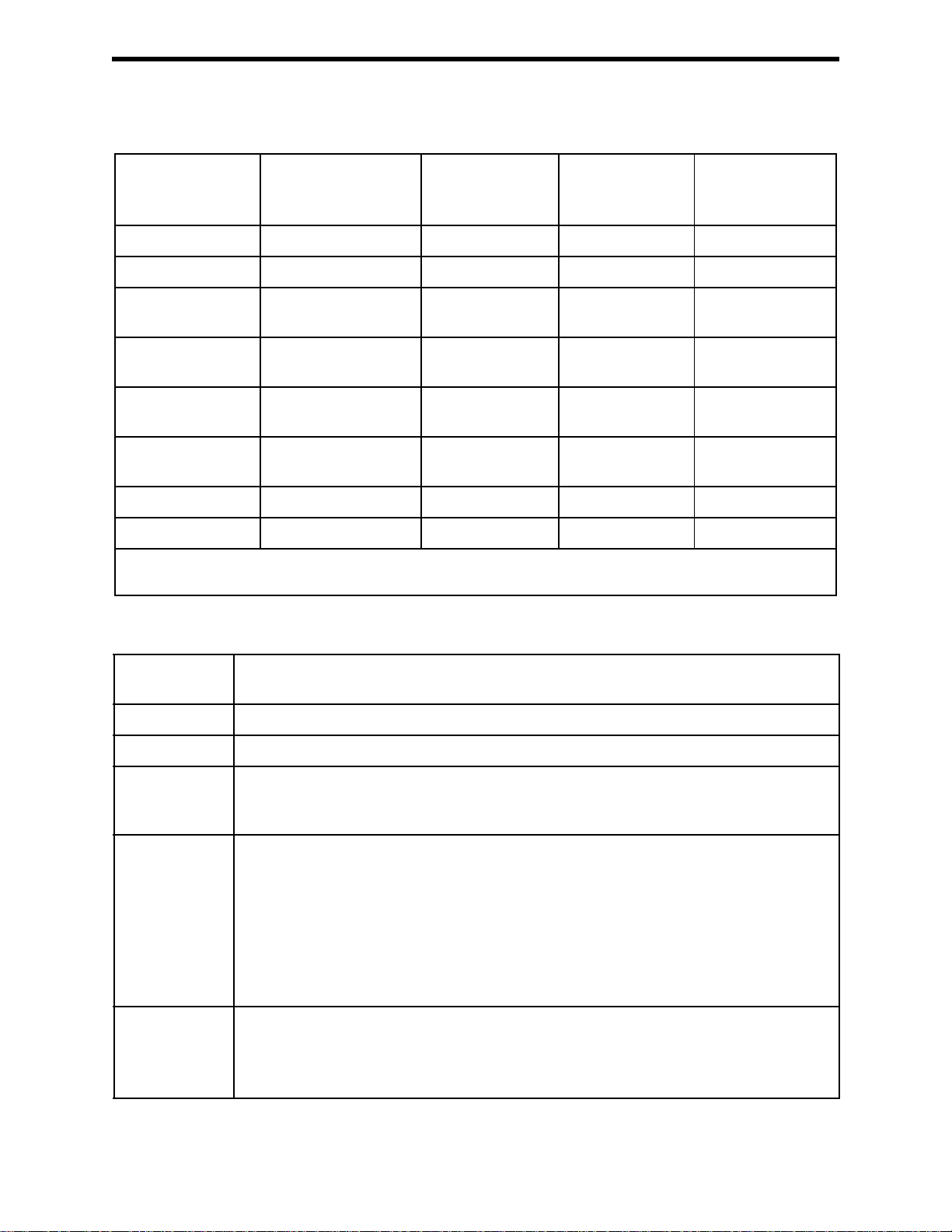
Table 1: Standard Sensor Specifications/Alarm Points
Combustible Gas,
Methane (CH
) Cali-
4
Oxygen (O
)Hydrogen
2
Sulfide (H
S)
2
Carbon
Monoxide (CO)
bration Standard*
Detection Range 0 - 100% LEL 0 - 25% volume 0 - 100.0 ppm 0 - 500 ppm
Service Range n/a 25.1 - 40% volume 100.1 - 200.0 ppm 501 - 2,000 ppm
Reading
1% LEL 0.1% volume 0.1 ppm 1 ppm
Increment
War nin g
Factory Setting
Alarm
Factory Setting
Alarm H
Factory Setting
10% LEL** 19.5% volume,
decreasing**
25% LEL 18.0% volume,
decreasing
50% LEL 23.5% volume,
increasing
5.0 ppm** 25 ppm**
30.0 ppm 50 ppm
100.0 ppm 1200 ppm
STEL Alarm n/a n/a 5.0 ppm 200 ppm
TWA Alarm n/a n/a 1.0 ppm 25 ppm
* The GX-3R is a l s o av ai lab l e se t up for general hydroc a r bo ns an d calibrated to a combustible gas other than methane, such
as isobutane. Consult RKI Instruments, Inc. for further information.
Table 2: GX-3R Specifications
Sampling
Method
Response Time T90 within 30 seconds
Display Graphics LCD Display
Operating
Temperature &
Continuous environment: -20°C to 50
Temporary environment (up to 15 minutes): -40°C to 60
Humidity
Indication
Accuracy for
Detection
Range
Combustible Gas, Catalytic Type Sensor
• ± 5% of reading or ± 2% LEL (whichever is greater)
Oxygen
• ± 0.5% O
2
Hydrogen Sulfide
• ± 5% of reading or ± 2 ppm H
S (whichever is greater)
2
Carbon Monoxide
• ± 5% of reading or ± 5 ppm CO (whichever is greater)
Indication
Accuracy for
Service Range
Oxygen
• ± 3.0% O
2
Hydrogen Sulfide and Carbon Monoxide
• ± 20% of reading
Diffusion
°
C/Below 90% RH
°
C/Below 95% RH
GX-3R Operator’s Manual Chapter 1: Introduction • 7
Page 8
Safety/
Regulatory
Power Supply Lithium ion battery pack
• ATEX: II 1 G Ex da ia IIC T4 Ga
Certificate Number: DEKRA 17ATEX0103 X
• IECEx: Ex da ia IIC T4 Ga
Certificate Number: IECEx DEK 17.0050X
• CSA classified, “C/US”, as Intrinsically Safe. Exia. Class I, Groups A, B, C, & D.
Temperature Code T3A. (pending)
C US
186718
Continuous
Operating
Hours
@ 25 °C
Case High-impact Plastic, RF Shielded, Dust and Weather Proof (IP66/68)
Included
Accessories
Other
Accessories
Dimensions and
Wei gh t
25 hours in Measuring Mode (Non Alarm Operation, Fully Charged)
• Alligator clip
• Rubber boot
•Wrist strap
• Calibration cup
• Single-unit charger cable
• Multi-unit charger cable
• Belt clip
•SDM-3R
•RP-3R
• IrDA/USB Cable for connecting to a computer when using the Data Logger Management
Program (not needed if computer has an infrared port)
Approximately 65(H) x 58(W) x 26(D) mm (2.6”H x 2.3”W x 1.0”D)
Approximately 100 g (3.5 oz.)
About this Manual
The GX-3R Operator’s Manual uses the following conventions for notes, cautions, and
warnings.
NOTE: Describes additional or critical information.
CAUTION: Describes potential damage to equipment.
WARNING: Describes potential danger that can result in injury or death.
8 • Chapter 1: Introduction GX-3R Operator’s Manual
Page 9
Chapter 2: Description
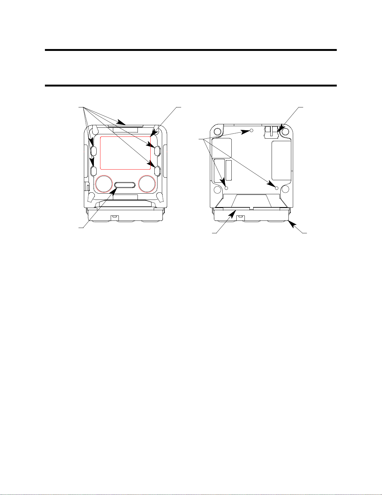
GX-3R
POWER
MODE
CO/H2SLELO2
AIR
Bottom
Cover
Charging
Socket
Sensor
Retainer
Buzzer
Opening
Front Back
LCDLEDs
Threaded
Inserts
Overview
This chapter describes the GX-3R instrument and its accessories.
Instrument Description
Figure 1: Component Location
Case
The GX-3R’s sturdy, high-impact plastic case is radio frequency (RF) resistant and is
suitable for use in many environmental conditions, indoors and out. The case is dust proof
and water resistant. A clear plastic window is located on the front of the case for viewing
the LCD. The black bottom cover is located on the bottom of the case and allows access to
the filters and sensors. A sensor retainer and filter gasket help orient and retain the sensor
and filters.
Three threaded inserts on the back of the case allow for installation of an alligator clip or
belt clip.
LCD
The digital LCD (liquid crystal display) simultaneously shows the gas reading for all
installed sensors. The LCD also shows information for each of the GX-3R’s operating
modes.
GX-3R Operator’s Manual Chapter 2: Description • 9
Page 10

Control Buttons
Two control buttons, AIR and POWER MODE, are located below the LCD.
Table 3: GX-3R Control Button Functions
Button Function(s)
AIR • turns on LCD backlight
• resets alarm condition if LATCHING is set to ON in Maintenance Mode
• enters User Mode, Maintenance Mode, and Gas Select Mode when used
with POWER MODE button
• activates the demand zero function (adjusts the GX-3R’s fresh air reading)
• changes the value of a parameter available for adjustment
• scrolls through parameter options
POWER MODE • turns the GX-3R on and off
• turns on LCD backlight
• enters and scrolls through Display Mode
• enters instructions into the GX-3R’s microprocessor
• resets alarm condition if LATCHING is set to ON in Maintenance Mode
• enters User Mode, Maintenance Mode, and Gas Select Mode when used
with AIR button
Alarm LEDs
The six alarm LEDs around the edge of the case alert you to gas, low battery, and failure
alarms.
Buzzer
One solid-state electronic buzzer is located inside the case. A hole in the middle front of
the case allow the sound to exit the case. The buzzer sounds for gas alarms, malfunctions,
low battery voltage, and as an indicator during use of the GX-3R’s many display and
adjustment options.
Vibrator
A vibrating motor inside the GX-3R case vibrates for gas alarms, unit malfunctions, and
as an indicator during normal use of the various modes of the GX-3R.
NOTE: If STEALTH is set to ON, the vibrator only functions when VIB in the
STEALTH Gas Select Mode item is set to ON. See “Stealth and Vibrator
Settings (STEALTH)” on page 102.
Sensors
The GX-3R uses three sensors to monitor combustible gas, oxygen (O2), carbon monoxide
(CO), and hydrogen sulfide (H2S) simultaneously. The sensors are located inside the
GX-3R and are held in their sockets by the sensor retainer and bottom cover. The sensors
use different detection principles, as described below.
Combustible Gas Sensor
The combustible gas sensor detects combustible gas in the %LEL range. It uses a catalytic
element for detection. The reaction of gas with oxygen on the catalyst causes a change in
the resistance of the element which affects the current flowing through it. The current is
amplified by the GX-3R’s circuitry, converted to a measurement of combustible gas
concentration, and displayed on the LCD.
10 • Chapter 2: Description GX-3R Operator’s Manual
Page 11

The standard calibration for the combustible gas sensor is to methane but the sensor will
still detect and respond to a variety of combustible gases.
O2/CO/H2S Sensors
The O2, CO, and H2S sensors are electrochemical cells that consist of two precious metal
electrodes in a dilute acid electrolyte. A gas permeable membrane covers the sensor face
and allows gas to diffuse into the electrolyte. The gas reacts in the sensor and produces a
current proportional to the concentration of the target gas. The current is amplified by the
GX-3R’s circuitry, converted to a measurement of gas concentration, and displayed on the
LCD.
There are 4 different types of CO and H2S sensors available:
• CO only (ESR-A13P): A single electrochemical cell that detects CO. Instruments with
this sensor cannot detect H2S.
•H2 compensated CO (ESR-A1CP): A single electrochemical cell that detects CO. This
sensor does not respond to or responds minimally to hydrogen. Instruments with this
sensor cannot detect H
S.
2
•H
S only (ESR-A13i): A single electrochemical cell that detects H2S. Instruments
2
with this sensor cannot detect CO.
•CO/H2S (ESR-A1DR): A combination electrochemical cell that detects both CO and
H2S.
Dummy Sensors
Any unit that has less than 3 sensors will have a dummy sensor installed in one or more
unused sensor positions. Dummy sensors are factory installed. The flat side of the dummy
sensor should face away from the GX-3R and the hollow side should face toward the
GX-3R.
Filters
H2S Removal Filter Disk (Dark Red)
An H2S removal filter disk is placed into a recess in the filter gasket over the combustible
gas sensor. It prolongs the life of the sensor by preventing H2S in the ambient air from
reaching the combustible gas sensor. The H2S filter disk is dark red in color and although
it may darken over time, its color is not indicative of remaining filter life.
The H2S filter disk can absorb H2S for 33 ppm hours and should be replaced after that
much exposure. With this many ppm hours of absorption, the H
replaced after 80 minutes of exposure to 25 ppm H2S. This equates to replacing the H2S
filter disk after 40 2-minute calibrations with a cylinder containing 25 ppm H2S. If H2S
exists in the monitoring environment, the H2S filter disk will have to be replaced more
frequently.
S filter disk should be
2
Charcoal Filter (Black)
A black charcoal filter is placed into a recess in the filter gasket over the CO sensor. The
charcoal filter disk scrubs H2S and certain hydrocarbons out of the sample to avoid false
CO readings. If false or elevated CO readings are noticed, especially in the presence of
H
S, change the charcoal filter.
2
If your instrument has a combo CO/H2S sensor, it will have a filter installed that is half
GX-3R Operator’s Manual Chapter 2: Description • 11
Page 12

black charcoal filter and half white humidity filter.
Humidity Filter (White)
A white humidity filter covers the H2S sensor.
If your instrument has a combo CO/H2S sensor, it will have a filter installed that is half
black charcoal filter and half white humidity filter.
Hydrophobic Dust Filter
The oval-shaped hydrophobic dust filter sits on the filter gasket, covering the sensor ports
and the filters.
Infrared Communications Port
An infrared (IR) communications port is located on the top of the case, near the top LEDs.
The data transmitted through the port is in standard IrDA protocol. A computer’s infrared
port or an IrDA/USB cable connected to a USB port can be used to download data saved
by the GX-3R to a computer using the GX-3R Data Logger Management Program. See the
GX-3R Data Logger Management Program operator’s manual for data logging and
downloading instructions.
Charging Socket and Battery Pack
A charging socket on the back of the instrument allows for charging cable connection.
A lithium ion (Li-ion) battery pack powers the GX-3R. At 25°C the battery lasts at least
25 hours. The battery icon in the upper right of the LCD shows remaining battery life.
When the GX-3R detects a low battery voltage, a low battery warning is activated. When
battery voltage is too low for Measuring Mode, the GX-3R sounds a dead battery alarm.
The battery pack can be recharged by using the GX-3R charging cable. The battery pack is
not user-replaceable.
NOTE: Use of batteries or battery chargers not specified by RKI Instruments, Inc. will
compromise the CSA classification and may void the warranty. See
“Recharging the Batteries” on page 74.
WARNING: To prevent ignition of a hazardous atmosphere, batteries must only be
changed or charged in an area known to be nonhazardous.
AVERTISSEMENT:Pour éviter l’inflammation d’une atmosphère dangereuse, les
batteries doivent uniquement être modifiés ou facturés dans une zone
connue comme non dangereuse.
12 • Chapter 2: Description GX-3R Operator’s Manual
Page 13
Included Accessories
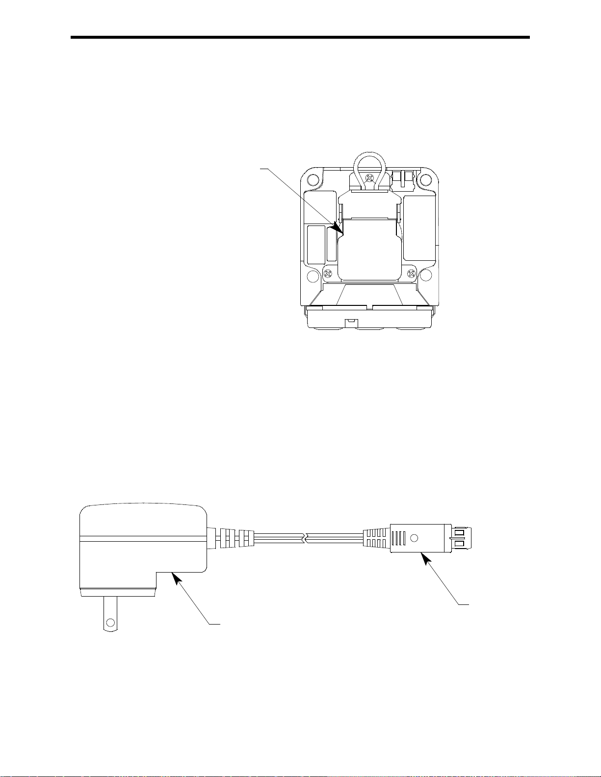
Alligator Clip
AC Adapter
Charging
Plug
Alligator Clip
An alligator clip is installed on the back of the GX-3R. The alligator clip can be used to
attach the GX-3R to clothing or a belt. Teeth in the alligator clip’s jaws prevent the unit
from slipping off. The alligator clip can be rotated to change how the instrument is
oriented when worn.
Figure 2: Alligator Clip
Rubber Boot
A black rubber boot is installed on the GX-3R.
Wrist Strap
A wrist strap is included with the GX-3R and can be attached to the wrist strap installation
feature on the left side of the GX-3R’s case.
Single-Unit Charging Cable
The charging cable has an AC adapter on one end and a charging plug that connects to the
GX-3R on the other end.
Figure 3: Charging Cable
GX-3R Operator’s Manual Chapter 2: Description • 13
Page 14

Calibration Cup
FRONT
Use the calibration cup to apply gas during a bump test, calibration, or gas test. The
calibration cup has an installation orientation to observe. “Front” and “rear” imprinting on
the bottom of the cup correspond to the front and rear of the GX-3R Pro when the
calibration cup is installed. In addition, a “front” label on the front of the calibration cup
should be visible when viewing the LCD with the calibration cup installed.
Other Accessories
Multi-Unit Charger
The multi-unit charger is a wall plug style adapter that plugs into a bar. The bar has five
4-foot cables coming out one side. The end of each of the five cables has a plug that
connects to the GX-3R’s power jack. The AC adapter is rated 100 - 240 VAC input, 5.99
VDC output.
Figure 4: Calibration Cup
Belt Clip
A belt clip makes it easy to hook the GX-3R to a utility belt.
SDM-3R
The SDM-3R is a calibration station for the GX-3R and GX-3R Pro. The station’s buttons
can be used for operations (Standalone Mode) or a computer can be used to control the
docking station (PC Controlled Mode). See the appropriate SDM-3R manual for more
information.
RP-3R
The RP-3R is a pump that allows sample to be drawn to the GX-3R.
IrDA Cable
Unless your computer has a built-in IrDA port, an IrDA cable is needed to establish
communication between the GX-3R and the Datalogging Program or the User Setup
Program.
14 • Chapter 2: Description GX-3R Operator’s Manual
Page 15
Chapter 3: Measuring Mode
RESUME
7:49
SEC
5
Overview
This chapter explains how to use the GX-3R to perform confined space entry monitoring
or general area monitoring in Measuring Mode. Display Mode is accessed from
Measuring Mode by pressing POWER MODE and is described in “Chapter 4: Display
Mode” on page 29.
Start Up
This section explains how to start up the GX-3R, get it ready for operation, and turn it off.
NOTE: The screens illustrated in this section are for a standard 4-gas unit. The screens
displayed by your GX-3R may be slightly different.
Turning On the GX-3R
To illustrate certain functions, the following description of the GX-3R start up sequence
assumes that the following menu items in User Mode are turned on: LUNCH, CAL
RMDR, and BUMP.RMDR in User Mode, and ID DISP and AUTOZERO in
Maintenance Mode. If any of these items are turned off, then the corresponding screens
will not appear.
1 . Press and briefly hold down POWER MODE. Release the button when you hear a
beep.
2 . If LUNCH is set to ON (factory setting if OFF, see “Updating the Lunch Break
Setting (LUNCH)” on page 65), the Lunch Break Screen appears. The unit counts
down from 5 seconds.
a. Continue Accumulating
average (TWA) readings from the last time the GX-3R was used, press and
release POWER MODE or allow the countdown to reach 0. The short-term
exposure limit (STEL) reading is reset each time the GX-3R is turned on.
b. Reset Accumulation: To reset the accumulation of peak and time-weighted
average (TWA) readings, press and release AIR before the countdown reaches 0.
: To continue accumulating peak and time-weighted
GX-3R Operator’s Manual Chapter 3: Measuring Mode • 15
Page 16
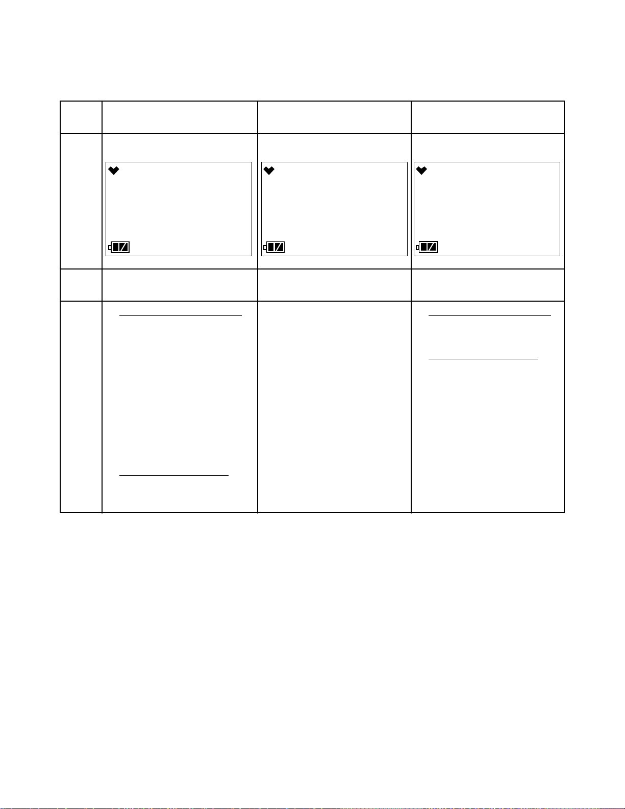
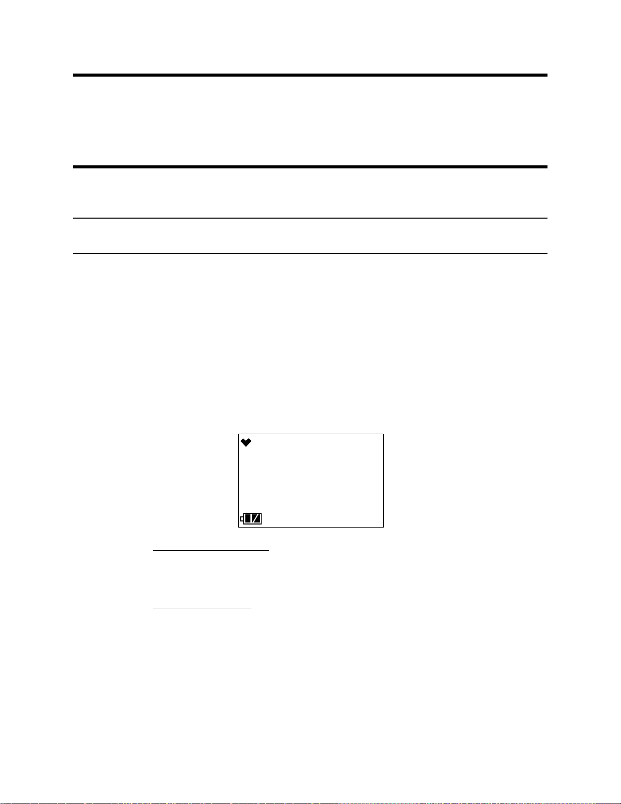
3 . If CAL RMDR is set to ON (factory setting) and a calibration is due, the screen that
CAL--LMT
7:49
CAL
CAL--LMT
7:49
FAIL
NEXT CAL
7:49
0 d
appears next depends on how CAL EXPD is set in User Mode (see “CAL EXPD” on
page 57). The three possible screens are described below. If a calibration is not due,
the instrument will tell you how many days are left until a calibration is due.
CAL EXPD set to
CONFIRM (factory setting)
LCD
Sound Buzzer sounds double pulsing tone Buzzer sounds double pulsing
tone
Action • Option A, Perform calibration
Press and release POWER
MODE to enter User Mode to
perform a calibration. See
“Performing a Calibration (GAS
CAL)” on page 47 for
calibration instructions.
If the calibration was success-
ful, the screen above will not
appear again until the unit is due
for calibration. If the calibra-
tion was not successful, the
screen above will again appear
in the startup sequence.
• Option B, Bypass message
continue without performing a
calibration, press and release
AIR.
: To
:
The GX-3R cannot be used until a
successful calibration has been
performed. Press and release
POWER MODE to enter User
Mode and perform a calibration.
See “Performing a Calibration
(GAS CAL)” on page 47 for cali-
bration instructions.
If the calibration was successful,
the screen above will not appear
again until the unit is due for cali-
bration. If the calibration was not
successful, the screen above will
again appear in the startup
sequence.
CAL EXPD set to
CANT USE
CAL EXPD set to
NONE
None
• Option A, Perform calibration
If you want to enter User Mode
to perform a calibration, press
and release POWER MODE.
• Option B, Bypass message
continue without performing a
calibration, wait a few seconds
for the instrument to continue
with its startup sequence.
: To
:
16 • Chapter 3: Measuring Mode GX-3R Operator’s Manual
Page 17
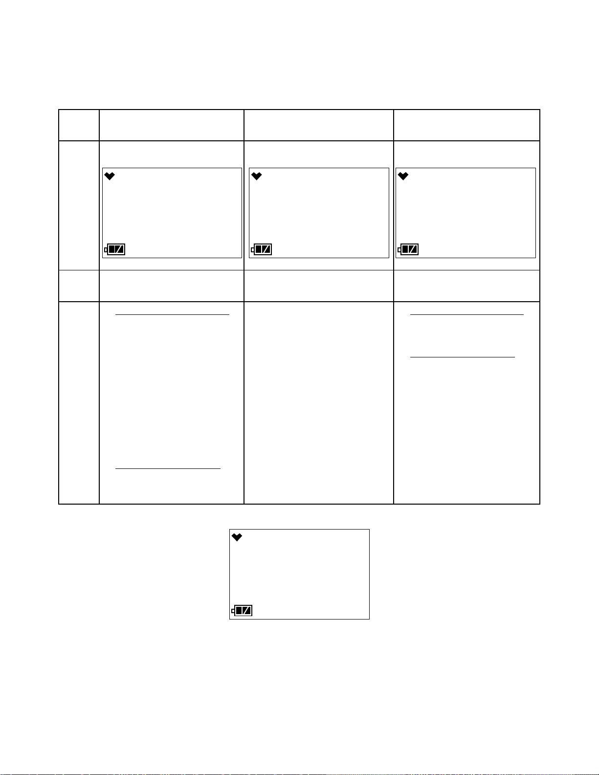
4 . If BUMP.RMDR is set to ON (factory setting is OFF) and a bump test is due, the
BUMP--LMT
7:49
CAL
BUMP--LMT
7:49
FAIL
NEXT BP
7:49
0 d
7:49
7:49
18 - 12.22
screen that appears next depends on how BUMP.EXPD is set in User Mode (see
“BUMP.EXPD” on page 61). The three possible screens are described below. If a
bump test is not due, the instrument will tell you how many days are left until a bump
test is due.
BUMP.EXPD set to
CONFIRM (factory setting)
LCD
Sound Buzzer sounds double pulsing
tone
Action • Option A, Perform bump test
Press and release POWER
MODE to enter User Mode to
perform a bump test. See
“Performing a Bump Test
(BUMP)” on page 43 for bump
test instructions.
If the bump test was success-
ful, the screen above will not
appear again until the unit is
due for bump testing. If the
bump test was not successful,
the screen above will again
appear in the startup sequence.
• Option B, Bypass message
continue without performing a
bump test, press and release
AIR.
: To
BUMP.EXPD set to
CANT USE
Buzzer sounds double pulsing tone None
The GX-3R cannot be used until a
:
successful bump test has been per-
formed. Press and release POWER
MODE to enter User Mode and
perform a bump test. See “Per-
forming a Bump Test (BUMP)” on
page 43 for bump test instructions.
If the bump test was successful, the
screen above will not appear again
until the unit is due for bump testing. If the bump test was not suc-
cessful, the screen above will again
appear in the startup sequence.
BUMP.EXPD set to
NONE
• Option A, Perform bump test
If you want to enter User Mode
to perform a bump test, press
and release POWER MODE.
• Option B, Bypass message
continue without performing a
bump test, wait a few seconds
for the instrument to continue
with its startup sequence.
: To
:
5 . The Date/Time Screen appears for a few seconds.
GX-3R Operator’s Manual Chapter 3: Measuring Mode • 17
Page 18
6 . The Battery Voltage Screen appears for a few seconds.
AL - L V
7:49
3.8
bAtt
7:49
CO H2S
ppm ppm
CH4 O2
%LEL %
F. S.
7:49
2000 200.0
CO ppm H2S ppm
100 40.0
CH4 %LEL O2 %
WARNING
7:49
25 5.0
CO ppm H2S ppm
10 19.5
CH4 %LEL O2 %
ALARM
7:49
50 30.0
CO ppm H2S ppm
25 18.0
CH4 %LEL O2 %
ALARM H
7:49
1200 100.0
CO ppm H2S ppm
50 23.5
CH4 %LEL O2 %
STEL
7:49
200 5.0
CO ppm H2S ppm
TWA
7:49
25 1.0
CO ppm H2S ppm
An “AL-L” at the bottom of the screen indicates that the alarms are set to latching.
An “AL-A” at the bottom of the screen indicates that the alarms are set to auto reset.
See “Setting Alarms to Latching or Self-Resetting (LATCHING)” on page 89 for a
description of how to change this parameter.
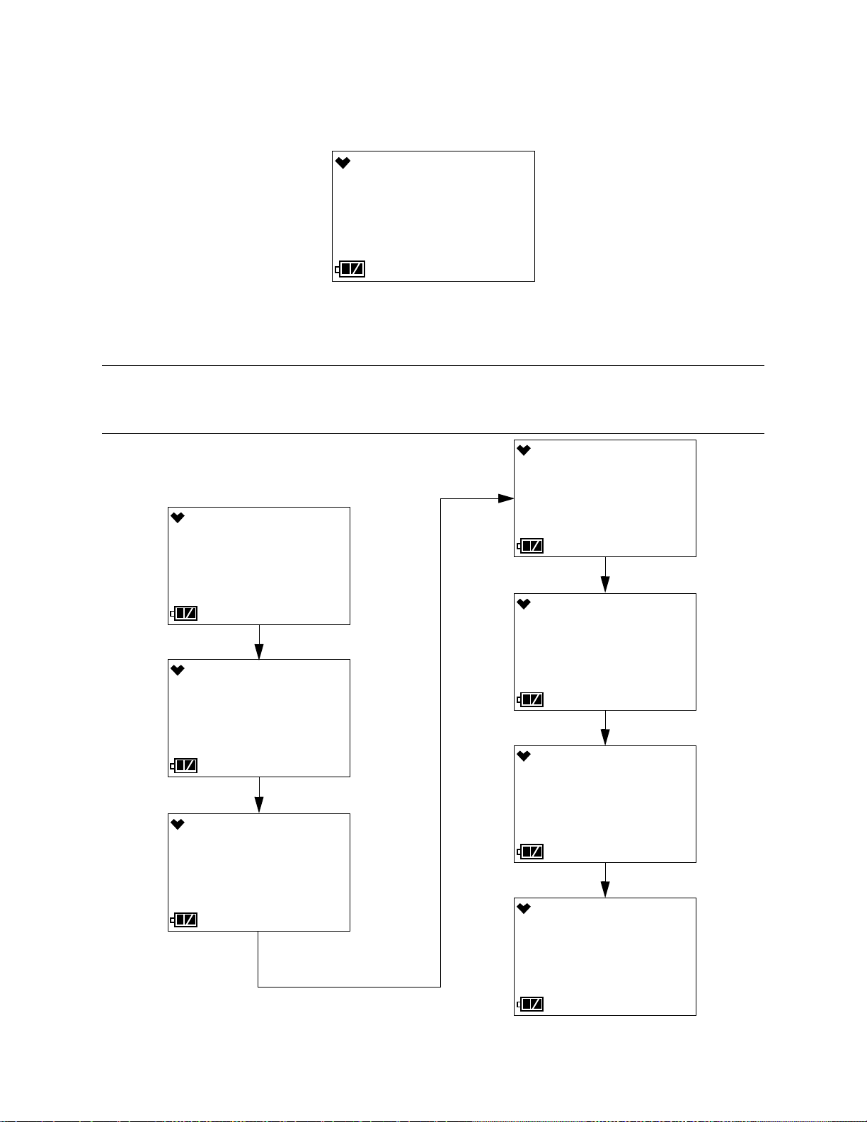
7 . The following screens display for 3 seconds each: the Gas Name Screen, the Full
Scale Screen, the Warning Setpoint Screen, the Alarm Setpoint Screen, the Alarm H
Setpoint Screen, the STEL Alarm Screen, and TWA Alarm Screen.
NOTE: If the combustible gas is set to something other than CH4 or H2 in Gas Select
Mode, the combustible channel is displayed as “HC” and the gas formula for
the combustible gas sensor’s target gas appears during startup.
18 • Chapter 3: Measuring Mode GX-3R Operator’s Manual
Page 19
8 . If ID DISP is set to ON (factory setting is OFF, see “Turning the ID Display
U_ID_001
7:49
USEr Id
S_ID_001
7:49
Stn Id
SENSOR
7:49
FAIL
CH4 %LEL
AUTOZERO
7:49
YES / MODE
7:49
NO / AIR
7:49
Function On/Off (ID DISP)” on page 90), the User ID Screen appears for a few
seconds, followed by the Station ID Screen.
9 . If the GX-3R experiences a sensor failure during start up, a screen indicating which
sensor failed appears and the buzzer sounds a double pulsing tone once per second.
In the example below, the combustible gas sensor has failed.
Press and release POWER MODE to acknowledge the failure and continue. The gas
reading for the failed sensor will be replaced by “- - - -”. Replace the failed sensor as
soon as possible.
10 . If AUTOZERO is set to ON (factory setting is OFF, see “Turning the Auto Zero
Function On/Off (AUTOZERO)” on page 90), the instrument prompts you to do an
auto zero. An auto zero operation sets the combustible gas, H2S, and CO channels to
zero and the OXY channel to 20.9%.
WARNING: Make sure that the instrument is in a known fresh air environment (an
environment free of combustible or toxic gases and of normal oxygen
content, 20.9%) before performing an auto zero operation. If you
perform an auto zero operation in an area with gases present, the
adjustment will not be accurate.
You must press and release the POWER MODE button to perform an auto zero
function. If you do not press any key, after 15 seconds, the instrument will enter
Measuring Mode without performing an auto zero.
GX-3R Operator’s Manual Chapter 3: Measuring Mode • 19
Page 20

11 . The GX-3R is now monitoring for gas in Measuring Mode. The Measuring Mode
7:49
0 0.0
CO ppm H2S ppm
0 20.9
CH4 %LEL O2 %
Screen appears displaying the current gas reading for each target gas.
Performing a Demand Zero
Before using the GX-3R, it is recommended to set the fresh air readings for the target
gases by performing a demand zero. This will set the combustible gas, H2S, and CO
channels to zero and the OXY channel to 20.9%.
1 . Find a fresh-air environment. This is an environment free of toxic or combustible
gases and of normal oxygen content (20.9%).
2 . Turn on the unit as described above in “Turning On the GX-3R”.
3 . Press and hold AIR. The LCD prompts you to continue holding AIR and the buzzer
will pulse while you hold the button (if KEY TONE is set to ON in User Mode).
4 . Continue to hold AIR until the LCD prompts you to release it. The GX-3R will set
the fresh air reading for all channels. Start up is complete and the unit is now ready
for monitoring.
Turning Off the GX-3R
1 . Press and hold POWER MODE.
2 . TURN OFF will appear on the display and the buzzer will pulse for about five
seconds (if KEY TONE is set to ON in User Mode).
3 . Release the button when TURN OFF disappears from the display.
20 • Chapter 3: Measuring Mode GX-3R Operator’s Manual
Page 21
Measuring Mode Operation
S 7:49
0 0.0
CO ppm H2S ppm
0 20.9
CH4 LEL O2 %
7:49
0 0.0
CO ppm H2S ppm
0 20.9
CH4 %LEL O2 %
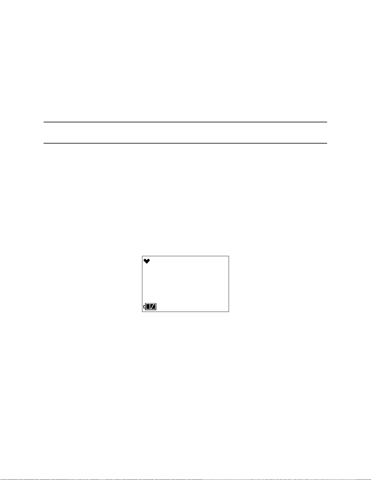
When the GX-3R completes its startup sequence, it is in Measuring Mode. In Measuring
Mode the GX-3R continuously monitors the sampled atmosphere and displays the gas
concentrations present for its target gases. The GX-3R is considered to be in Normal
Operation if there are no alarm indications.
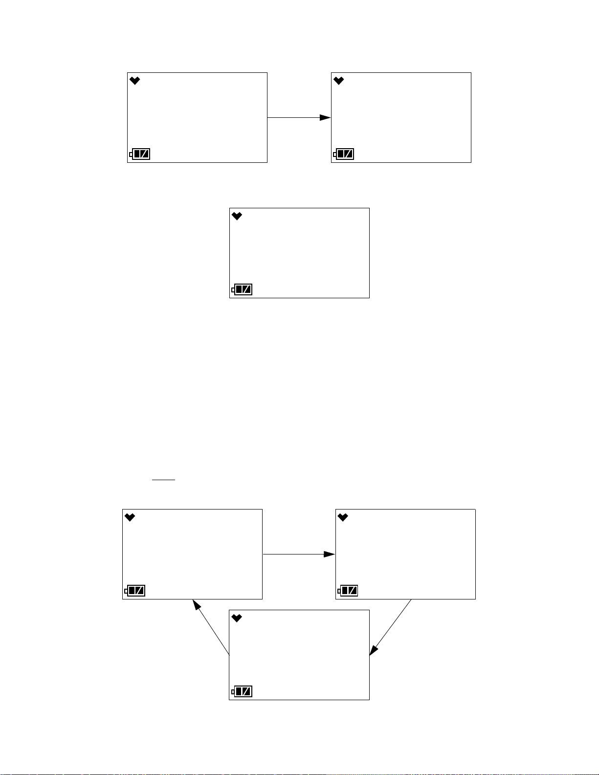
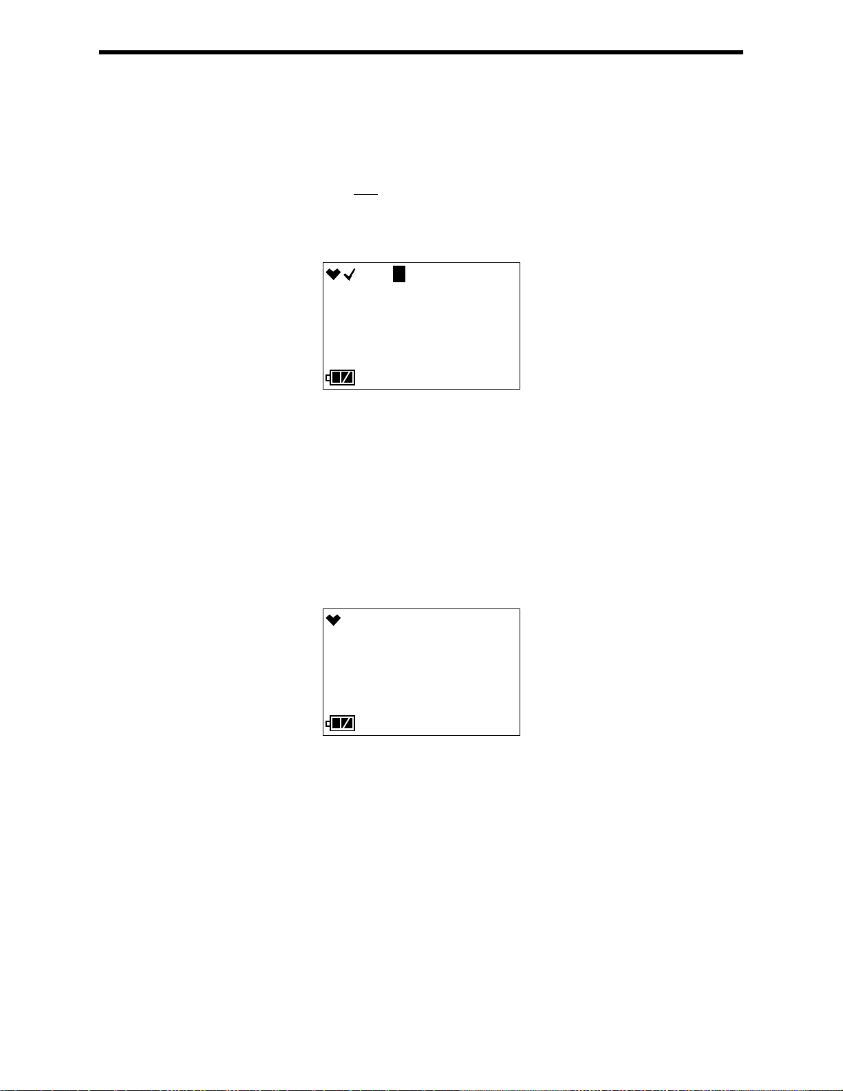
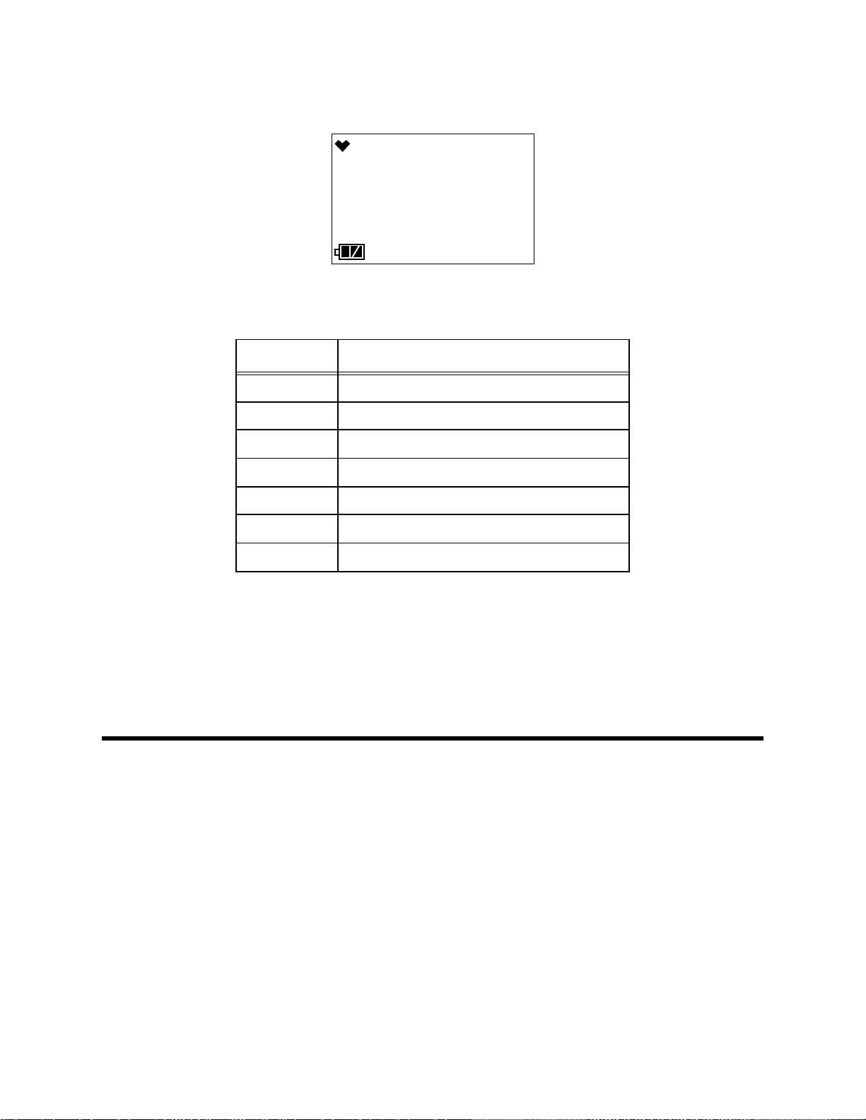
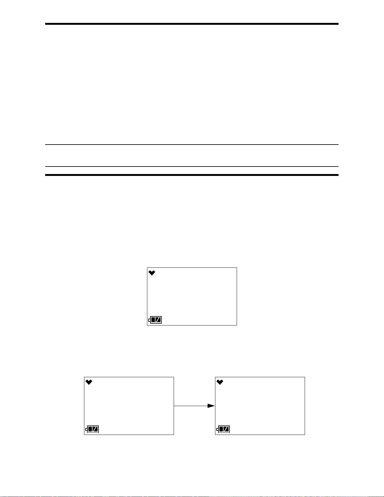
If BUMP.RMDR is set to ON and if a bump test is not due, a check mark will appear in
the upper left corner of the LCD.
If the instrument is operating in Stealth Mode, an “S” will appear at the top of the LCD.
In a low-light environment, press and release either button to turn on the display backlight.
See “Updating the Backlight Time (BL TIME)” on page 68 to program backlight duration.
If the BEEP menu item in User Mode is set to anything other than OFF, the GX-3R will
give periodic indications to confirm that it’s operating or to indicate a non-compliance
(see “Setting the Confirmation Beep and Non-Compliance Indicator (BEEP)” on
page 66).
Monitoring an Area
1 . Start up the GX-3R as described above in “Start Up” on page 15. It is now in
Measuring Mode.
2 . Take the GX-3R to the monitoring area.
3 . Wait at least 15 seconds and observe the display for gas readings. If a reading is
observed, allow the reading to stabilize to determine the gas concentrations present.
4 . If a gas alarm occurs, take appropriate action. See “Responding to Alarms” on
page 25.
GX-3R Operator’s Manual Chapter 3: Measuring Mode • 21
Page 22

Combustible Gas Detection
There are three issues to keep in mind when monitoring for combustible gas.
• The combustible gas sensor will respond to any combustible gas. The standard
calibration gas for the combustible gas channel is methane (CH4). If the instrument is
setup for and calibrated to a different combustible gas, such as hexane or propane, the
the gas name right above the readings displays as “HC”.
The table below lists the conversion factors for several hydrocarbon gases if the GX-
3R is calibrated to methane. To use this table, multiply the display reading on the
combustible gas channel by the factor in the appropriate row to obtain the actual gas
concentration. For example, if you are detecting ethylene and the display reads 10%
LEL for the combustible gas channel, you actually have 10% LEL x 1.20 = 12.0% LEL
ethylene present.
Table 4: LEL Hydrocarbon Conversions
Gas
Acetone 0.45 IPA 0.61
Acetylene 0.70 Isobutane 0.91
Benzene 0.40 MEK 0.38
Butadiene 0.66 Methane- 1.00
Cyclopentane 0.69 Methanol 0.55
DME 0.86 MIBK 0.25
Ethane 1.06 MMA 0.30
Ethanol 0.51 Nonane 0.11
Ethyl Acetate 0.35 Propane 0.89
Ethylene 1.20 Propylene 1.03
Heptane 0.32 THF 0.43
Hexane 0.53 Toluene 0.22
Hydrogen 1.05 Xylene 0.13
LEL Conversion Factor
(from CH
Cal.)
4
Gas
LEL Conversion Factor
(from CH4 Cal.)
• The GX-3R provides the combustible gas sensor with some protection against
exposure to high levels of combustible gas which can damage the sensor. It does this
by turning off the combustible gas sensor power temporarily when it determines that
an over scale (more than 100 %LEL) concentration of combustible gas is present that
may damage the sensor. Nevertheless, concentrations of combustible gas of more than
100 %LEL can still affect the zero level or calibration of the combustible gas sensor if
the concentration is high enough.
CAUTION: Do not expose the combustible gas sensor to high concentrations of
combustible gas such as that from a butane lighter. Exposure to high
concentrations of combustible gas may adversely affect the performance of
the sensor.
22 • Chapter 3: Measuring Mode GX-3R Operator’s Manual
Page 23

CAUTION: Any rapid increase in the combustible gas reading on the combustible gas
• Some gases such as silicone vapors, chlorinated hydrocarbons, and sulphur
Alarms
This section covers alarm indications in Measuring Mode. It also describes how to reset
the GX-3R after an alarm has occurred and how to respond to an alarm condition.
NOTE: False alarms may be caused by radio frequency (RF) or electromagnetic (EMI)
Alarm Indications
channel followed by a declining or erratic reading may indicate a gas
concentration above the LEL which may be hazardous.
compounds can contaminate the detection elements inside the combustible gas sensor
damaging the sensor and result in reduced response to combustible gas. Make every
effort to avoid these gases.
The H2S scrubber disks protect the combustible sensor from H2S, but you should
avoid other sulphur compounds.
interference. Keep the GX-3R away from RF and EMI sources such as radio
transmitters or large motors.
The GX-3R buzzer will sound an alarm, the LEDs will flash, and the vibrator will pulse
when any sort of alarm condition or failure is encountered. If the GX-3R is operating in
Stealth Mode, the buzzer will not sound and the vibrator’s operation will depend on the
VIB setting in Gas Select Mode’s STEALTH menu item. See pg.102 for more
information.
NOTE: If an alarm condition occurs while you are in Display Mode, the GX-3R will
automatically bring up the alarm screen instead.
The table below summarizes the types of alarms produced by the GX-3R and their
indications.
Table 5: Alarm Types and Indications
Alarm Type Visual Indications Other Indications
War nin g
Concentration of gas rises above
the Warning setting or falls below
the Warning setting for O
.
2
• Affected channel’s gas reading, gas
name, and units flash
• WARNING appears at the bottom of
the LCD
• Alarm LEDs flash in circle sequence
once per second
• Backlight turns on
• High-low tone sounding
once per second
• Vibrator pulses once per
second
Alarm
Concentration of gas rises above
the Alarm setting.
GX-3R Operator’s Manual Chapter 3: Measuring Mode • 23
• Affected channel’s gas reading, gas
name, and units flash
• ALARM appears at the bottom of the
LCD
• Alarm LEDs flash in circle sequence
twice per second
• Backlight turns on
• High-low tone sounding
twice per second
• Vibrator pulses twice per
second
Page 24
Table 5: Alarm Types and Indications
Alarm Type Visual Indications Other Indications
Alarm H
Concentration of gas rises above
the Alarm H setting or falls below
the Alarm H setting for O
.
2
• Affected channel’s gas reading, gas
name, and units flash
• ALARM H appears at the bottom of
the LCD
• Alarm LEDs flash in circle sequence
twice per second
• Backlight turns on
TWA or STEL
Concentration of CO or H
S rises
2
above the TWA or STEL alarm set-
ting.
• Affected channel’s gas reading, gas
name, and units flash
• TWA or STEL appears at the bottom
of the LCD
• Alarm LEDs flash in circle sequence
once per second
• Backlight turns on
Over Range • Affected channel’s gas reading is
replaced with a flashing
• Gas name and units flash
• OVER appears at the bottom of the
LCD
• Alarm LEDs flash in circle sequence
twice per second
• Backlight turns on
Minus Over Range • Affected channel’s gas reading is
replaced with a flashing
• Gas name and units flash
• M OVER appears at the bottom of
the LCD
• Alarm LEDs flash in circle sequence
twice per second
• Backlight turns on
• High-low tone sounding
twice per second
• Vibrator pulses twice per
second
• High-low tone sounding
once per second
• Vibrator pulses once per
second
• High-low tone sounding
twice per second
• Vibrator pulses twice per
second
• High-low tone sounding
twice per second
• Vibrator pulses twice per
second
Low Battery Warning • The last bar in the battery icon
None
disappears and the battery icon starts
flashing
Dead Battery Alarm • Gas readings disappear. FA IL
appears in the middle of the screen
Double pulsing tone once per
second
and BATTERY appears at the
bottom of the screen.
• Alarm LEDs flash once per second
Sensor Failure • SENSOR appears at the bottom of
the screen and the failed sensor(s) are
Double pulsing tone once per
second
indicated with FAI L under the gas
name.
• Alarm LEDs flash once per second
Clock Failure • FAIL appears in the middle of the
screen and CLOCK appears at the
Double pulsing tone once per
second
bottom of the screen.
• Alarm LEDs flash once per second
24 • Chapter 3: Measuring Mode GX-3R Operator’s Manual
Page 25

Table 5: Alarm Types and Indications
Alarm Type Visual Indications Other Indications
System Failure • FAIL SYSTEM appears at the
bottom of the screen and an error
code displays in the middle
• Alarm LEDs flash once per second
Double pulsing tone once per
second
Responding to Alarms
This section describes response to gas, over range, battery, sensor failure, clock failure,
and system failure alarms.
Responding to Gas Alarms
1 . Determine which gas alarm has been activated.
2 . Follow your established procedure for an increasing gas condition or a decreasing
oxygen condition.
3 . Reset the alarm as necessary or allowed.
a. If LATCHING is set to ON (factory setting) in Maintenance Mode, the gas
reading must fall below (or rise above for an oxygen low alarm) an alarm setting
before you can reset the alarm condition using POWER MODE or AIR.
b. If LATCHING is set to OFF in Maintenance Mode, the alarm condition will
automatically reset when gas reading falls below (or rises above for an oxygen
low alarm) an alarm setpoint.
Responding to Over Range Alarms
WARNING: An over range condition may indicate an extreme combustible gas,
toxic gas, or oxygen concentration. Confirm the gas concentration with
a different GX-3R or with another gas detecting device.
CAUTION: High off-scale readings may indicate an explosive concentration.
PRUDENCE: Des lectures élevées hors échelle peuvent indiquer une concentration
explosive.
1 . Determine which channel is in alarm.
2 . Follow your established procedure for an extreme gas condition.
3 . Reset the alarm using POWER MODE or AIR once the alarm condition has cleared
if LATCHING is set to ON (factory setting) in Maintenance Mode.
4 . Calibrate the GX-3R as described in “Chapter 5: User Mode and Calibration” on
page 39.
5 . If the over range condition continues or if you are not able to successfully calibrate
the unit, you may need to replace the sensor that has triggered the over range alarm.
6 . If the over range condition continues after you have replaced the sensor, contact RKI
Instruments, Inc. for further instructions.
GX-3R Operator’s Manual Chapter 3: Measuring Mode • 25
Page 26
Responding to Battery Alarms
CLOCK
7:49
FAIL
WARNING: The GX-3R is not operational as a gas monitoring device during a dead
battery alarm. Take the Model GX-3R to a non-hazardous area and
replace or recharge the batteries as described in “Recharging the
Batteries” on page 74.
The GX-3R is fully functional during a low battery warning. However, only a limited
amount of operating time remains, approximately 1 - 2 hours. The amount of time depends
on how often the LCD backlight is used and how often the unit is responding to alarm
conditions. Recharge the battery as soon as possible as described in “Recharging the
Batteries” on page 74.
NOTE: Alarms and the LCD back light consume battery power and reduce the amount
of operating time remaining.
Responding to Sensor Failure Alarms
1 . Determine which sensor has triggered the sensor failure alarm.
2 . Try calibrating the failed sensor, as described in “Chapter 5: User Mode and
Calibration” on page 39 before replacing it.
3 . If the sensor failure continues, replace the sensor as described in “Replacing a
Sensor” on page 78.
4 . If the sensor failure condition continues after you have replaced the sensor, contact
RKI Instruments, Inc. for further instructions.
Responding to Clock Failure Alarms
A clock failure alarm occurs if the unit’s internal clock malfunctions.
1 . Press and release POWER MODE to continue into Measuring Mode.
CAUTION: There will be no datalogging function if you operate the instrument after a
clock failure.
2 . Attempt to set the date using the DATE menu item in User Mode. See “Setting the
Date/Time (DATE)” on page 70.
3 . If the date cannot be set correctly, contact RKI Instruments, Inc. as soon as possible.
26 • Chapter 3: Measuring Mode GX-3R Operator’s Manual
Page 27
Responding to System Failure Alarms
SYSTEM
7:49
031
FAIL
1 . If a system failure occurs, the system failure screen will display an error code as
shown below:
2 . The error code meanings are shown in the table below:
Table 6: Error Code Explanation
Error Code Explanation
000 ROM failure
010 RAM failure
021 FRAM failure
3 . If the error code is anything but 031 as shown above, the instrument cannot be used.
Contact RKI Instruments, Inc. as soon as possible.
If the error code is 031, you may press and release POWER MODE to continue into
Measuring Mode if the instrument must be used temporarily.
CAUTION: There will be no datalogging function if you operate the instrument after a
Data Logging
The GX-3R features the ability to log data to its internal memory and download it to a
computer via the infrared communications port on the front of the unit. It logs gas readings
in Measuring Mode, alarm data, and calibration data.
To utilize the GX-3R’s downloading capability, you will need the GX-3R Data Logger
Management Program and a computer with an infrared port or a USB port that runs one of
the following operating systems: Windows 7, Windows 8, or Windows 10. If your
computer has an infrared port, then no additional accessories are needed to download data
from the GX-3R. If your computer does not have an infrared port but does have a USB
port, a USB/IrDA adapter cable can be used to download data from the GX-3R using the
USB port. The GX-3R Data Logger Management Program is available at
www.rkiinstruments.com/gx3r. The USB/IrDA adapter cable is available from RKI
Instruments, Inc.
031 FLASH memory failure
080 Acceleration sensor failure
081 PCB failure
082 Temperature sensor failure
031 system failure. Contact RKI Instruments, Inc. as soon as possible.
GX-3R Operator’s Manual Chapter 3: Measuring Mode • 27
Page 28

The data logging capacity depends on how often the GX-3R stores data, how many
channels are active, and how often the GX-3R is turned on and off. The table below
illustrates how much data logging time is available for the various interval times. It
assumes that the unit has the standard four sensors, is only turned on once, and there are
no alarm occurrences. The data logging interval time must be set using the GX-3R Data
Logger Management Program.
Table 7: Data Logging Capacity
Interval Time Data Logging Time
10 seconds 10 hours
20 seconds 20 hours
30 seconds 30 hours
1 minute 60 hours
3 minutes 180 hours
5 minutes 300 hours
10 minutes 600 hours
For a complete description of the Data Logger Management Program and procedures for
downloading data to a computer, see the GX-3R Data Logger Management Program
Operator’s Manual.
28 • Chapter 3: Measuring Mode GX-3R Operator’s Manual
Page 29

Chapter 4: Display Mode
This section describes Display Mode which is accessible from Measuring Mode. See
Table 8 below for a list of Display Mode’s menu items, a short description of each item,
and the page number for further description.
Table 8: Display Mode Menu Items
Display Mode
Menu Item
Description
PEAK (pg.30) Displays the Peak readings for each sensor.
STEL (pg.31) Displays the STEL readings (CO and H
TWA (pg.31) Displays the TWA readings (CO and H
A
LIST (pg.32)
Change the target gas for the catalytic sensor.
• CH4 (methane)
• i-C4H10 (isobutane)
• H2 (hydrogen)
• CH3OH (methanol)
• C2H2 (acetylene)
• C2H4 (ethylene)
• C2H6 (ethane)
• C2H5OH (ethanol)
• C3H6 (propylene)
• C3H6O (acetone)
• C3H8 (propane)
• C4H6 (butyne)
• C5H10 (cyclopentane)
S only).
2
S only).
2
• C6H6 (benzene)
• n-C6H14 (hexane)
• C7H8 (toluene)
• n-C7H16 (heptane)
• C8H10 (xylene)
• n-C9H20 (nonane)
• EtAc (ethyl acetate)
• IPA (isopropyl alcohol)
• MEK (methyl ethyl ketone)
• MMA (methyl methacrylate)
• DME (dimethyl ether)
• MIBK (methyl isobutyl ketone)
• THF (tetrahydrofuran)
USER ID
B
(pg.33)
STN ID
B
(pg.34)
CAL DATA
C
(pg.35)
BUMP DATA
D
(pg.36)
View and/or change the User ID.
View and/or change the Station ID.
Displays the last calibration date for each sensor.
Displays the last bump test date for each sensor.
TEMP (pg.37) Displays the current date, time, and temperature.
ALARM--PT
View alarm points
(pg.37)
A
Only appears if DISP SET is set to ON in User Mode (factory setting) and if CH4 or i-C4H10 is
selected for the combustible gas in Gas Select Mode.
B
Only appears if DISP SET is set to ON in User Mode (factory setting) and if ID DISP is set to ON in
Maintenance Mode (factory setting is OFF).
C
Only appears if CAL RMDR is set to ON in User Mode (factory setting).
D
Only appears if BUMP.RMDR is set to ON in User Mode (factory setting is OFF).
GX-3R Operator’s Manual Chapter 4: Display Mode • 29
Page 30
Tips for Using Display Mode
PEAK
7:49
135 37.5
CO ppm H2S ppm
24 17.3
CH4 %LEL O2 %
HOLD AIR
7:49
CLEAr
RELEASE
7:49
CLEAr
• To enter Display Mode and scroll from one menu item to the next or skip an item when
a question is asked, press and release POWER MODE.
• To enter an item, press and release AIR.
• To change a flashing parameter, use AIR. To reverse the direction of movement in a
list (ie. from down to up or vice versa):
a. Press and hold AIR.
b. Immediately press POWER MODE and then release both buttons.
• To exit from an entered-information screen and go back to the main menu, press and
release POWER MODE.
NOTE: Each screen displays for 20 seconds. If you do not press a button within 20
seconds, the GX-3R automatically returns to Measuring Mode.
Peak Screen (PEAK)
The peak screen displays the highest (lowest for oxygen) concentrations detected since the
GX-3R was turned on. Peak readings are stored in the GX-3R’s memory until a higher
level is detected (lower for oxygen), the peak reading is cleared, or the GX-3R is turned
off.
The lunch break feature enables the GX-3R to save peak readings when it is turned off so
it can continue with the same peaks when it is turned on again. See “Turning On the GX3R” on page 15.
To clear the peak readings, do the following:
1 . After entering Display Mode, press and release POWER MODE until PEAK
appears.
2 . Press and hold AIR until the screen prompts you to release it.
3 . The peak readings will be reset and the unit will return to the Peak Screen.
30 • Chapter 4: Display Mode GX-3R Operator’s Manual
Page 31

If you do not want to clear the peak readings, release AIR before the above screen
STEL
7:49
10 2.0
CO ppm H2S ppm
TWA
7:49
5 0.5
CO ppm H2S ppm
sequence occurs. The unit will return to the Peak Screen.
STEL Screen (STEL)
The STEL Screen displays the short term exposure limit (STEL) readings for H2S and CO
only. The STEL reading is the average reading over the last 15 minutes.
TWA Screen (TWA)
The TWA Screen displays the time weighted average (TWA) readings for H2S and CO
only.
The TWA reading is the average reading over the last 8 hours. If 8 hours have not elapsed
since the last time the TWA reading was cleared, the average is still calculated over 8
hours. The missing time is assigned a 0 value for readings. If LUNCH is set to OFF
(factory setting), the TWA is cleared when the GX-3R is turned off.
If LUNCH is set to ON, the GX-3R will remember TWA readings when it is turned off so
it can continue them when it is turned on again. See “Turning On the GX-3R” on page 15.
GX-3R Operator’s Manual Chapter 4: Display Mode • 31
Page 32

Changing the Combustible Gas Sensor’s Gas (LIST)
LIST
7:49
HC GAS
CH4
7:49
SELECT
HC GAS
The LIST screen allows you to select the target gas for the combustible gas sensor. This
screen only appears if DISP SET in User Mode is set to ON (factory setting) and if CH4
or iC4H10 is selected for the combustible channel in Gas Select Mode.
If you select a new target gas, the change is saved if you turn the instrument off and on.
1 . After entering Display Mode, press and release POWER MODE until LIST appears.
2 . Press and release AIR to enter the screen. The current gas will flash at the bottom of
the screen.
3 . Use AIR to scroll through the list of gases.
• CH4 (methane)
• i-C4H10 (isobutane)
• H2 (hydrogen)
• CH3OH (methanol)
• C2H2 (acetylene)
• C2H4 (ethylene)
• C2H6 (ethane)
• C2H5OH (ethanol)
• C3H6 (propylene)
• C3H6O (acetone)
• C3H8 (propane)
• C4H6 (butyne)
• C5H10 (cyclopentane)
• C6H6 (benzene)
• n-C6H14 (hexane)
• C7H8 (toluene)
• n-C7H16 (heptane)
• C8H10 (xylene)
• n-C9H20 (nonane)
• EtAc (ethyl acetate)
• IPA (isopropyl alcohol)
• MEK (methyl ethyl ketone)
• MMA (methyl methacrylate)
• DME (dimethyl ether)
• MIBK (methyl isobutyl ketone)
• THF (tetrahydrofuran)
4 . When the desired gas is displayed, press and release POWER MODE. The changes
are saved and the instrument returns to the LIST screen.
5 . The gas formula displays at the bottom of the Measuring Mode screen. The gas
selection remains selected if you turn the instrument off and on again.
32 • Chapter 4: Display Mode GX-3R Operator’s Manual
Page 33

Changing the User ID (USER ID)
U_ID_002
7:49
USEr Id
CHG / AIR
7:49
USEr Id
NO / MODE
7:49
USEr Id
U_ID_002
7:49
USEr Id
This screen only appears if DISP SET in User Mode is set to ON (factory setting) and if
ID DISP in Maintenance Mode is set to ON (factory setting is OFF).
Use this screen to select a user ID from the 128 user IDs that are stored in the GX-3R’s
memory. Before a user ID is selected on a brand new instrument, the user ID is “----------”.
The factory-installed user IDs have a “U_ID_XXX” format.
The user ID provides a way to identify the GX-3R user during a data logging session. If
the user ID is changed during an operating session, a new data session is initiated with the
new user ID attached to it.
User IDs can only be selected in this menu item. In order to edit the 128 user IDs, you
must use the GX-3R Datalogging Program.
1 . After entering Display Mode, press and release POWER MODE until the USER ID
screen sequence appears.
2 . To change the User ID, press and release AIR. The current User ID will flash.
3 . Use AIR to scroll to the desired User ID. To reverse the scrolling direction:
a. Press and hold AIR.
b. Immediately press POWER MODE and then release both buttons.
4 . Press and release POWER MODE to save the User ID and return to the USER ID
screen in Display Mode.
GX-3R Operator’s Manual Chapter 4: Display Mode • 33
Page 34

Changing the Station ID (STN ID)
S_ID_002
7:49
Stn Id
CHG / AIR
7:49
Stn Id
NO / MODE
7:49
Stn Id
S_ID_002
7:49
Stn Id
This screen only appears if DISP.SET in User Mode is set to ON (factory setting) and if
ID DISP in Maintenance Mode is set to ON (factory setting is OFF).
Use this screen to select a station ID from the 128 station IDs that are stored in the
GX-3R’s memory. Before a station ID is selected on a brand new instrument, the station
ID is “----------”. The factory-installed station IDs have a “S_ID_XXX” format.
The station ID provides a way to identify the GX-3R location during a data logging
session. If the station ID is changed during an operating session, a new data session is
initiated with the new station ID attached to it.
User IDs can only be selected in this menu item. In order to edit the 128 user IDs, you
must use the GX-3R Datalogging Program.
1 . After entering Display Mode, press and release POWER MODE until the STN ID
screen sequence appears.
2 . To change the Station ID, press and release AIR. The current Station ID will flash.
3 . Use AIR to scroll to the desired Station ID. To reverse the scrolling direction:
34 • Chapter 4: Display Mode GX-3R Operator’s Manual
a. Press and hold AIR.
b. Immediately press POWER MODE and then release both buttons.
4 . Press and release POWER MODE to save the Station ID and return to the STN ID
screen in Display Mode.
Page 35

Last Successful Calibration Date (CAL DATA)
CAL DATA
7:49
dISP
CAL DATA
7:49
CH4
18- 12. 20
CAL DATA
7:49
O2
18- 12. 20
CAL DATA
7:49
H2S
18- 12. 20
CAL DATA
7:49
CO
18- 12. 20
AIR AIR
AIR
AIR
The CAL DATA screen shows the date of the last successful calibration for each of the
installed sensors. This screen only appears if CAL.RMDR is set to ON.
1 . After entering Display Mode, press and release POWER MODE until CAL DATA
appears.
2 . Press AIR to enter the CAL DATA screen and to scroll through the installed sensors.
3 . When you are done viewing the last calibration date for the sensors, press and release
POWER MODE to return to the CAL DATA screen in Display Mode.
GX-3R Operator’s Manual Chapter 4: Display Mode • 35
Page 36

Last Successful Bump Test Date (BUMP DATA)
BUMP DATA
7:49
dISP
BUMP DATA
7:49
CH4
18- 12. 20
BUMP DATA
7:49
O2
18- 12. 20
BUMP DATA
7:49
H2S
18- 12. 20
BUMP DATA
7:49
CO
18- 12. 20
AIR AIR
AIR
AIR
The BUMP DATA screen shows the date of the last successful bump test for each of the
installed sensors. This screen only appears if BUMP.RMDR is set to ON.
1 . After entering Display Mode, press and release POWER MODE until BUMP DATA
appears.
2 . Press AIR to enter the BUMP DATA screen and to scroll through the installed
sensors.
3 . When you are done viewing the last bump test date for the sensors, press and release
POWER MODE to return to the BUMP DATA screen in Display Mode.
36 • Chapter 4: Display Mode GX-3R Operator’s Manual
Page 37

Date, Time, Temperature Screen (TEMP)
22°C
7:49
7:49
18- 12. 26
ALARM--PT
7:49
dISP
The TEMP screen shows the date and time of the instrument and the temperature of the
surrounding area.
Alarm Points Screen (ALARM--PT)
The Alarm Points Screen allows you to view the gas alarm settings for all active channels.
1 . After entering Display Mode, press and release POWER MODE until ALARM--PT
appears.
2 . Press and release AIR. The Full Scale Settings screen will appear showing full scale
settings for each channel.
GX-3R Operator’s Manual Chapter 4: Display Mode • 37
Page 38

3 . Use AIR to scroll through the Warning, Alarm, Alarm H, STEL, and TWA settings.
F.S .
7:49
2000 200.0
CO ppm H2S ppm
100 40.0
CH4 %LEL O2 %
WARNING
7:49
25 5.0
CO ppm H2S ppm
10 19.5
CH4 %LEL O2 %
ALARM
7:49
50 30.0
CO ppm H2S ppm
25 18.0
CH4 %LEL O2 %
ALARM H
7:49
1200 100.0
CO ppm H2S ppm
50 23.5
CH4 %LEL O2 %
STEL
7:49
200 5.0
CO ppm H2S ppm
TWA
7:49
25 1.0
CO ppm H2S ppm
AIR
AIR
AIR
AIR
AIR
AIR
4 . Press and release POWER MODE to return to the Alarm Points Screen.
38 • Chapter 4: Display Mode GX-3R Operator’s Manual
Page 39

Chapter 5: User Mode and Calibration
Overview
This section describes the GX-3R in User Mode. See Table 9 below for a list of the items
found in User Mode, the page that the menu item’s instructions can be found on, and a
short description of the menu item.
Table 9: User Mode Menu Items
User Mode
Menu Item
BUMP (pg.43) Perform a bump test.
GAS CAL (pg.47) Perform a fresh air adjustment, perform a span adjustment, change the calibration gas
concentration, set the cylinder group.
AIR CAL
(pg.47)
AUTO CAL
(pg.48)
ESCAPE Return to the GAS CAL menu item.
CAL SET (pg.56) Change parameters related to calibration.
CAL RMDR
(pg.57)
Perform a fresh air adjustment.
AUTO CAL
CYL X
CAL-P Set the calibration gas concentration for each gas.
CYL SEL Assign a cylinder (A-E) to each gas (all 4 gases set to
ESCAPE Return to the AUTO CAL menu item.
ON
(factory setting): The instrument will notify the user upon startup
when a calibration is due. Notification type depends on CAL EXPD
setting below.
OFF
: No notification upon startup when a calibration is due.
Description
Perform an automatic span adjustment on the gases
selected for Cylinder X (A-E cylinders available).
Cylinder A is the default). For single cal operation, you
would assign each gas its own cylinder.
CAL INT
(pg.57)
CAL EXPD
(pg.57)
ESCAPE Return to the CAL SET menu item in User Mode.
How often the instrument needs to be calibrated.
Options: 1 - 1000 days (factory setting is 90 days)
Defines what action must be taken if a calibration is due upon startup.
CONFIRM
acknowledge that calibration is due and continue to Measuring Mode.
CANT USE
tion is performed.
NONE
continues.
(factory setting): Press and release POWER MODE to
: Cannot enter Measuring Mode until a successful calibra-
: A screen indicates that calibration is due but warmup sequence
GX-3R Operator’s Manual Chapter 5: User Mode and Calibration • 39
Page 40

Table 9: User Mode Menu Items
User Mode
Menu Item
BUMP SET
(pg.58)
Description
Change parameters related to bump testing.
SETTINGS
(pg.59)
BUMP.RMDR
(pg.61)
GAS TIME How long gas is applied during a bump test.
Choices: 30 (factory setting), 45, 60, 90 seconds
CHECK Percentage of calibration gas concentration that the
bump test reading must be within in order to pass
bump.
Options: 10%, 20%, 30%, 40%, 50% (factory setting)
CAL TIME How long gas is applied during a calibration. GAS
TIME is deducted from this time.
Options: 90 (factory setting) or 120 seconds
AUTO CAL ON
ESCAPE Return to the SETTINGS menu item in BUMP SET.
: The instrument will notify the user upon startup when a bump test
ON
is due. Notification type depends on BUMP.EXPD setting below.
OFF
(factory setting): No notification upon startup when a bump test is
due.
(factory setting): If a bump test fails, a calibration
is automatically started.
OFF
: If a bump test fails, a calibration is not automati-
cally started.
BUMP INT
(pg.61)
BUMP.EXPD
(pg.61)
ESCAPE Return to the BUMP SET menu item in User Mode.
ALARM-PT
(pg.62)
LUNCH (pg.65) ON
Set alarm points for all channels (WARNING, ALARM, ALARM H, STEL, TWA) or
reset all alarms to their default settings.
PEAK readings at startup.
OFF
readings every time it’s turned on.
How often the instrument needs to be bump tested.
Options: 0 - 30 days (factory setting is 30 days)
Defines what action must be taken if a bump test is due upon startup.
CONFIRM
acknowledge that bump test is due and continue to Measuring Mode.
CANT USE
test is performed.
NONE
continues.
: Lunch break feature is on. Instrument will ask if you want to resume TWA and
(factory setting): Lunch break feature is off. Instrument resets TWA and PEAK
(factory setting): Press and release POWER MODE to
: Cannot enter Measuring Mode until a successful bump
: A screen indicates that bump test is due but warmup sequence
40 • Chapter 5: User Mode and Calibration GX-3R Operator’s Manual
Page 41

Table 9: User Mode Menu Items
User Mode
Menu Item
BEEP (pg.66) Set confirmation beep parameters.
BEEP SEL
(pg.66)
LED: LEDs will flash and instrument will vibrate based on interval
defined in BEEP INT to confirm instrument is still operating.
BUZZER
: Buzzer will sound and instrument will vibrate based on
interval defined in BEEP INT to confirm instrument is still operating.
LED+BUZZ
: LEDs will flash, buzzer will sound, and instrument will
vibrate based on interval defined in BEEP INT to confirm instrument
is still operating.
BUMP/CAL
: LEDs flash based on interval defined in BEEP INT if
bump test or calibration is due.
ALM ALRT
: LEDs flash based on interval defined in BEEP INT if
instrument goes into a gas alarm.
B/C/ALM
: LEDs flash based on interval defined in BEEP INT if
a) bump test is due, b) calibration is due, or c) instrument goes into a
gas alarm.
OFF
(factory setting): No alerts to confirm instrument is still operating
or that a bump test or calibration is due.
BEEP INT
(pg.67)
Confirmation alert interval. Confirmation type defined in BEEP SEL.
Options: 0.5 minute and 1 to 99 minutes in 1 minute increments. The
factory setting is 5 minutes.
Description
ESCAPE Return to the BEEP menu item in User Mode.
BL TIME (pg.68) How long the back light stays on after the last button press.
Options: 0 - 255 seconds or OFF. The factory setting is 30 seconds.
KEY TONE
(pg.68)
DISP SET (pg.69) OFF
ON
(factory setting): Buzzer will sound when button is pressed.
OFF
: Buzzer will not sound when button is pressed.
: LIST, USER ID, and STN ID screens do not appear in Display Mode.
ON
(factory setting): LIST item appears in Display Mode. USER ID and STN ID
screens appear if ID DISP in Maintenance Mode is also set to ON.
ZERO SUP
(pg.69)*
ON
(factory setting): Not intended for field adjustment. The suppression values are:
Combustible Gas: 2% LEL
O
: 0.5% volume
2
H
S: 0.3 ppm
2
CO: 2 ppm
ZERO.FLWR
(pg.69)**
ON
(factory setting): Not intended for field adjustment. Oxygen channel does not support
zero follower functionality.
DATE (pg.70) Set the instrument’s date and time.
PASSWORD
(pg.70)
ROM/SUM
ON
: A password is needed to access User Mode. Factory-set password is 0405.
OFF
(factory setting): No password is needed to access User Mode.
View the firmware information for the GX-3R’s sensor board and main board.
(pg.71)
START (pg.72) Press and release POWER MODE to begin the warmup sequence and enter Measuring
Mode.
GX-3R Operator’s Manual Chapter 5: User Mode and Calibration • 41
Page 42

Table 9: User Mode Menu Items
PASSWORD set to OFF PASSWORD set to ON
PASSWORD
M 7:49
0 0 0 0
BUMP
M 7:49
BUMP
M 7:49
User Mode
Menu Item
* Only appears if ZSUP.DISP is set to ON in Maintenance Mode.
** Only appears if ZFLW.DISP is set to ON in Maintenance Mode.
Entering User Mode
WARNING: The GX-3R is not in operation as a gas detector while in User Mode.
1 . Take the GX-3R to a non-hazardous location and turn it off if it is on.
2 . Press and hold AIR, then press and hold POWER MODE. When you hear a beep,
release the buttons.
3 . The screen that appears will depend on the setting of User Mode’s PASSWORD
item.
If PASSWO RD is set to OFF (factory setting), continue with Step 6.
If PASSWO RD is set to ON, continue with Step 4.
Description
4 . If PAS SWORD has been set to ON in User Mode, a password screen will appear.
The first digit will be flashing.
5 . Use AIR to select each password number then press POWER MODE to save it and
move on to the next number. To go back a number, press and hold AIR and POWER
MODE for a few seconds. To reverse the direction of change (ie. from increasing to
decreasing or vice versa):
a. Press and hold AIR.
b. Immediately press POWER MODE and then release both buttons.
6 . The BUMP menu item displays.
7 . Use AIR to move through the User Mode menu items.
42 • Chapter 5: User Mode and Calibration GX-3R Operator’s Manual
Page 43

Tips for Using User Mode
• To scroll from one menu item to the next, press and release AIR. To reverse the
scrolling direction:
a. Press and hold AIR.
b. Immediately press POWER/MODE and then release both buttons.
c. The scrolling direction returns to the original direction when you exit and reenter
a menu.
• To skip an item when a question is asked, press and release AIR.
• To enter an item and to save any changes, press and release POWER MODE.
• To change a flashing parameter, use AIR. To reverse the direction of change (ie. from
increasing to decreasing or vice versa):
a. Press and hold AIR.
b. Immediately press POWER MODE and then release both buttons.
• To exit an entered menu item without saving a change, press and hold AIR and
POWER MODE for a few seconds.
Performing a Bump Test (BUMP)
To bump test the GX-3R, you will need:
• Known calibrating samples of the gases being detected. The combustible and toxic gas
samples should have concentrations between 10 and 50% of the full scale value. For
example, if you are bump testing the combustible gas channel, your calibration
cylinder should have a combustible gas concentration between 10% LEL and 50%
LEL. An oxygen-free source, such as 100% nitrogen is recommended for setting the
oxygen zero but a concentration of up to 19.5% is acceptable.
CAUTION: Although the GX-3R can be bump tested with an oxygen concentration of
up to 19.5%, RKI Instruments, Inc. recommends that a multi-gas cylinder
have an oxygen concentration in the range of 10% - 16% oxygen.
• 0.25 LPM fixed flow regulator
• Non-absorbent tubing
• Calibration cup
1 . Confirm that the GX-3R’s calibration gas values match the concentrations listed on
the calibration gas cylinder(s) as described in “Setting the Calibration Values in
CAL--P” on page 52.
2 . Confirm that your cylinder selections are appropriate as described in “Making
Cylinder Selections in CYL SEL” on page 54.
3 . Confirm that the regulator knob is turned all the way clockwise. Screw the 0.25 LPM
fixed flow regulator onto the calibration cylinder.
GX-3R Operator’s Manual Chapter 5: User Mode and Calibration • 43
Page 44

4 . Install the calibration cup onto the GX-3R. Use the label and imprinting to make sure
GX-3R
AIR
POWER
MODE
CO/H2 SLELO2
FRONT
Inlet
BUMP
M 7:49
CYL A
M 7:49
50 25.0
CO ppm H2S ppm
50 12.0
CH4 %LEL O2 %
BUMP
M 7:49
50 25.0
CO ppm H2S ppm
50 12.0
CH4 %LEL O2 %
that the calibration cup gets installed in the correct orientation relative to the GX-3R.
Be sure the calibration cup is pushed on all the way.
Figure 5: Calibration Cup Installation
5 . Use the tubing to connect the regulator to the inlet of the calibration cup.
6 . While in User Mode, press AIR to scroll to BUMP.
7 . Press and release POWER MODE. The display will show the gases assigned to
Cylinder A and the assigned calibration values (see “Setting the Calibration Values in
CAL--P” on page 52 if the calibration values do not match the calibration gas
cylinder’s concentrations). The bottom of the screen will alternate between “CYL A”
and “BUMP”.
44 • Chapter 5: User Mode and Calibration GX-3R Operator’s Manual
8 . If necessary, use AIR to scroll to the Auto Cal screen for the gas(es) you want to
calibrate. As shipped from the factory, all gases are assigned to Cylinder A.
Page 45

9 . Turn the regulator knob counterclockwise to open the regulator.
APPLY
M 29
0 0.0
CO ppm H2S ppm
0 20.9
CH4 %LEL O2 %
BUMP
M 29
0 0.0
CO ppm H2S ppm
0 20.9
CH4 %LEL O2 %
BUMP/CAL
M 7:49
P F
CO ppm H2S ppm
P P
CH4 %LEL O2 %
BUMP/
M 7:49
47 2.0
CO ppm H2S ppm
47 11.9
CH4 %LEL O2 %
AIR
10 . Press and release POWER MODE.
11 . The gas readings will flash, the bottom of the screen will alternate between “APPLY”
and “BUMP”, and the top of the screen will count down from the time set in BUMP
SET\SETTINGS\GAS TIME.
To back out of the gas application screen without performing the bump test, press
and release AIR and POWER MODE together.
12 . When the BUMP SET\SETTINGS\A-CAL User Mode item is set to:
a. OFF, continue to Step 13.
b. ON, continue to Step 14.
13 . When the BUMP SET\SETTINGS\A-CAL User Mode item is set to OFF:
a. When the countdown is done, the instrument will indicate which channels passed
or failed the bump test with a P (pass) or an F (fail) underneath the gas name. You
can scroll between the bump test results and the bump test gas readings by
pressing and releasing AIR.
b. To return to the BUMP menu item in User Mode, press and release POWER
MODE.
c. If any channel failed the bump test, the LEDs will flash and the buzzer will sound
a double pulsing tone until you press and release POWER MODE to return to the
BUMP menu item in User Mode. See “Troubleshooting” on page 73.
d. Turn the regulator knob clockwise to close the regulator.
e. Continue to Step 15.
GX-3R Operator’s Manual Chapter 5: User Mode and Calibration • 45
Page 46

14 . When the BUMP SET\SETTINGS\A-CAL User Mode item is set to ON:
BUMP/CAL
M 7:49
P P
CO ppm H2S ppm
P P
CH4 %LEL O2 %
BUMP/
M 7:49
47 23.3
CO ppm H2S ppm
47 11.9
CH4 %LEL O2 %
AIR
AUTO CAL
M 59
23.3
H2S ppm
47
CH4 %LEL
If all channels pass the bump test:
a. When the countdown is done, the results screen appears. You can scroll between
the bump test results and the bump test gas readings by pressing and releasing
AIR.
b. To return to the BUMP menu item in User Mode, press and release POWER
MODE.
c. Turn the regulator knob clockwise to close the regulator.
d. Continue to Step 15.
If any channel fails the bump test:
a. A calibration is immediately and automatically started after the initial
countdown. Continue to apply the calibration gas. AUTO CAL will appear at the
bottom of the screen and a new countdown will appear at the top.
The calibration time counted down during a calibration initiated because of a
failed bump test is the difference between the GAS TIME and the CAL TIME
values defined in the BUMP SET\SETTINGS menu item in User Mode.
46 • Chapter 5: User Mode and Calibration GX-3R Operator’s Manual
Page 47

b. At the end of the calibration, the instrument displays the results from both the
BUMP/CAL
M 7:49
P F F
CO ppm H2S ppm
F P P
CH4 %LEL O2 %
BUMP/
M 7:49
47 2.0
CO ppm H2S ppm
5 11.9
CH4 %LEL O2 %
AIR
/CAL
M 7:49
2.5
H2S ppm
47
CH4 %LEL
AIR AIR
bump test and the calibration. Use AIR to scroll between the calibration/bump
test results, the bump test gas readings, and the calibration gas readings.
c. To return to the BUMP menu item in User Mode, press and release POWER
MODE.
d. If any channel failed the calibration, the LEDs will flash and the buzzer will
sound a double pulsing tone until you press and release POWER MODE to return
to the BUMP menu item in User Mode. See “Troubleshooting” on page 73.
e. Turn the regulator knob clockwise to close the regulator.
f. Continue to Step 15.
15 . Unscrew the regulator from the calibration cylinder.
16 . If necessary, repeat Step 1 though Step 15 for additional cylinders.
17 . Remove the calibration cup from the GX-3R.
18 . Store the calibration kit in a safe and convenient place.
Performing a Calibration (GAS CAL)
Calibration Notes
• To fully calibrate the sensors, you must do a fresh air adjustment (AIR CAL) and a
span adjustment (AUTO CAL).
• The optimum frequency of calibration depends heavily on how the GX-3R is used.
Instruments used daily may need to be calibrated weekly or monthly, while
instruments that are used only a few times a year may need to be calibrated before
each use. Typical calibration frequencies range from monthly to quarterly.
AIR CAL
1 . Find a fresh air environment, an environment of normal oxygen content (20.9%) that
is free of toxic and combustible gases.
GX-3R Operator’s Manual Chapter 5: User Mode and Calibration • 47
Page 48

2 . While in User Mode, press AIR to scroll to GAS CAL.
GAS CAL
M 7:49
AIR CAL
M 7:49
AIR CAL
M 7:49
0 0.0
CO ppm H2S ppm
0 20.9
CH4 %LEL O2 %
HOLD AIR
M 7:49
Air CAL
RELEASE
M 7:49
Adj
3 . Press and release POWER MODE. The AIR CAL menu item appears.
4 . Press and release POWER MODE to enter the AIR CAL menu.
5 . Press and hold AIR until the screen prompts you to release it.
6 . If the fresh air adjustment passes, the instrument returns to the GAS CAL menu.
7 . If the fresh air adjustment fails, “FAIL AIR” displays. Press and release POWER
MODE to acknowledge the failure. See “Troubleshooting” on page 73.
Performing a Span Adjustment in AUTO CAL
Preparing for a Span Adjustment
To adjust the span on the GX-3R, you will need:
• Known concentrations of the gases being detected. The combustible and toxic gas
samples should have concentrations between 10 and 50% of the full scale value. For
example, if you are calibrating the combustible gas channel, your calibration cylinder
should have a combustible gas concentration between 10% LEL and 50% LEL. An
oxygen-free source, such as 100% nitrogen is recommended for setting the oxygen
zero but a concentration of up to 19.5% is acceptable.
48 • Chapter 5: User Mode and Calibration GX-3R Operator’s Manual
Page 49

CAUTION: Although the GX-3R can be calibrated with an oxygen concentration of up
GX-3R
AIR
POWER
MODE
CO/H2 SLELO2
FRONT
Inlet
to 19.5%, RKI Instruments, Inc. recommends that a multi-gas cylinder have
an oxygen concentration in the range of 10% - 16% oxygen.
• 0.25 LPM fixed flow regulator
• Non-absorbent tubing
• Calibration cup
1 . Confirm that the GX-3R’s calibration gas values match the concentrations listed on
the calibration gas cylinder(s) as described in “Setting the Calibration Values in
CAL--P” on page 52.
2 . Confirm that your cylinder selections are appropriate as described in “Making
Cylinder Selections in CYL SEL” on page 54.
3 . Confirm that the regulator knob is turned all the way clockwise. Screw the 0.25 LPM
fixed flow regulator onto the calibration cylinder.
4 . Install the calibration cup onto the GX-3R. Use the label and imprinting to make sure
that the calibration cup gets installed in the correct orientation relative to the GX-3R.
Be sure the calibration cup is pushed on all the way.
GX-3R Operator’s Manual Chapter 5: User Mode and Calibration • 49
Figure 6: Calibration Cup Installation
5 . Use the tubing to connect the regulator to the inlet of the calibration cup.
Page 50

Performing a Span Adjustment
GAS CAL
M 7:49
AUTO CAL
M 7:49
CYL A
M 7:49
50 25.0
CO ppm H2S ppm
50 12.0
CH4 %LEL O2 %
AUTO CAL
M 7:49
50 25.0
CO ppm H2S ppm
50 12.0
CH4 %LEL O2 %
APPLY
M 7:49
0 0.0
CO ppm H2S ppm
0 20.9
CH4 %LEL O2 %
AUTO CAL
M 7:49
0 0.0
CO ppm H2S ppm
0 20.9
CH4 %LEL O2 %
1 . While in User Mode, press AIR to scroll to GAS CAL.
2 . Press and release POWER MODE. The AIR CAL menu item appears.
3 . Use AIR to scroll to the AUTO CAL menu item.
4 . Press and release POWER MODE. The display will show the gases assigned to
Cylinder A and the assigned calibration values (see “Setting the Calibration Values in
CAL--P” on page 52 if the calibration values do not match the calibration gas
cylinder’s concentrations). The bottom of the screen will alternate between “CYL A”
and “AUTO CAL”.
5 . If necessary, use AIR to scroll to the Auto Cal screen for the gas(es) you want to
calibrate. As shipped from the factory, all gases are assigned to Cylinder A.
6 . Press and release POWER MODE.
7 . The gas readings will flash and the bottom of the screen will alternate between
“APPLY” and “AUTO CAL”.
To back out of the gas application screen without performing the bump test, press
and release AIR and POWER MODE together.
8 . Turn the regulator knob counterclockwise to open the regulator.
50 • Chapter 5: User Mode and Calibration GX-3R Operator’s Manual
9 . Allow the gas to flow for 2 minutes.
Page 51

10 . Press and release POWER MODE.
AUTO CAL
M 7:49
50 25.0
CO ppm H2S ppm
FAIL 12.0
CH4 %LEL O2 %
11 . Turn the regulator knob clockwise to close the regulator.
12 . If the calibration passed:
a. The screen says “PASS”, shows the current gas readings, and the instrument
returns to the AUTO CAL menu item.
b. If MAX SPAN is set to ON in Gas Select Mode (see “Turning Calibration Max
Span On/Off (MAX SPAN)” on page 102), then before returning to the AUTO
CAL menu item, the instrument will indicate the maximum possible adjustment
it could have made to the response reading. So if the combustible gas channel
was calibrated with 50% LEL gas and the maximum indicated span is 95% LEL,
this means that there was enough adjustment left on that channel to set the
reading to 95% LEL when the detector was exposed to 50% LEL gas. If the
maximum span value is close to the calibration gas value, for example if it is 53%
LEL when exposed to 50% LEL gas, the sensor should be replaced soon. The
upper limit on the maximum adjustment indicated for all channels except for
oxygen is either twice the calibration value or full scale, whichever is lower. The
upper limit on the maximum adjustment indicated for the oxygen channel is
25.0% volume.
13 . If the calibration failed:
a. “FAIL” will replace the gas reading for the failed sensors.
b. The LEDs will flash and the buzzer will sound a double pulsing tone.
c. Press and release POWER MODE to clear the failure. The instrument returns to
the AUTO CAL menu item in the GAS CAL menu.
d. See “Troubleshooting” on page 73.
14 . Unscrew the regulator from the calibration cylinder.
15 . If necessary, repeat Step 1 though Step 14 for additional cylinders.
16 . Remove the calibration cup from the GX-3R.
17 . Store the calibration kit in a safe and convenient place.
18 . See “Exiting the GAS CAL Menu” on page 56 to return to the User Mode menu.
GX-3R Operator’s Manual Chapter 5: User Mode and Calibration • 51
Page 52

Setting the Calibration Values in CAL--P
GAS CAL
M 7:49
AUTO CAL
M 7:49
CAL--P
M 7:49
CAL--P
M 7:49
- - -
CH4 %LEL
1 . While in User Mode, press AIR to scroll to GAS CAL.
2 . Press and release POWER MODE. The AIR CAL menu item appears.
3 . Use AIR to scroll to the AUTO CAL menu item.
4 . Press and release POWER MODE. The Auto Cal screen for gases assigned to
Cylinder A will display.
5 . Use AIR to scroll to CAL--P.
6 . Press and release POWER MODE. The combustible gas channel will display.
52 • Chapter 5: User Mode and Calibration GX-3R Operator’s Manual
Page 53

7 . Use AIR to scroll to the channel whose calibration gas value you want to change.
CAL--P
M 7:49
- - -
CH4 %LEL
CAL--P
M 7:49
- - -
O2 %
CAL--P
M 7:49
- - -
H2S ppm
CAL--P
M 7:49
- - -
CO ppm
ESCAPE
M 7:49
AIR
AIR
AIR
AIR
AIR
CAL--P
M 7:49
50
CH4 %LEL
8 . Press and release POWER MODE. The calibration value will begin to flash. In the
example below, the combustible gas channel is selected.
9 . Use AIR to adjust the calibration gas value. The calibration gas value in the
instrument must match the value listed on the calibration gas cylinder you are using
for that channel.
NOTE: If you are using an RKI 4-gas cylinder, be sure to set the O2 channel to 12%, not
0%.
10 . Press and release POWER MODE to save the change. The calibration gas value
stops flashing and the unit returns to the channel selection screen.
11 . Repeat Step 7 through Step 10 for any other channels that need to be changed.
12 . Use AIR to scroll to ESCAPE.
GX-3R Operator’s Manual Chapter 5: User Mode and Calibration • 53
Page 54

13 . Press and release POWER MODE. The instrument will return to the CAL--P menu
GAS CAL
M 7:49
AUTO CAL
M 7:49
CYL SEL
M 7:49
item in the Auto Cal Menu.
14 . Press AIR to scroll to ESCAPE.
15 . Press and release POWER MODE. The instrument will return to the AUTO CAL
menu item in the GAS CAL Menu.
16 . See “Exiting the GAS CAL Menu” on page 56 to return to the User Mode menu.
Making Cylinder Selections in CYL SEL
The CYL SEL menu item allows you to group channels together for calibration. As
shipped from the factory, all channels are assigned to Cylinder A which means all
channels are calibrated at the same time. There are 5 cylinder assignments available: A, B,
C, D, and E. If you wanted to calibrate each channel separately, you need to assign each
channel to a different cylinder (ie. Cylinder A: combustible gas, Cylinder B: O2, Cylinder
C: H2S, Cylinder D: CO).
1 . While in User Mode, press AIR to scroll to GAS CAL.
2 . Press and release POWER MODE. The AIR CAL menu item appears.
3 . Use AIR to scroll to the AUTO CAL menu item.
4 . Press and release POWER MODE. The Auto Cal screen for gases assigned to
Cylinder A will display.
5 . Use AIR to scroll to CYL SEL.
54 • Chapter 5: User Mode and Calibration GX-3R Operator’s Manual
Page 55

6 . Press and release POWER MODE. The combustible gas channel will display.
CYL SEL
M 7:49
- - -
CH4 %LEL
CYL SEL
M 7:49
- - -
CH4 %LEL
CYL SEL
M 7:49
- - -
O2 %
CYL SEL
M 7:49
- - -
H2S ppm
CYL SEL
M 7:49
- - -
CO ppm
ESCAPE
M 7:49
AIR
AIR
AIR
AIR
CYL SEL
M 7:49
A
CH4 %LEL
7 . Use AIR to scroll to the channel whose cylinder assignment you want to change.
8 . Press and release POWER MODE. The current setting will flash. In the example
below, the combustible gas channel is selected.
9 . Use AIR to change the cylinder assignment. The choices are A, B, C, D, and E.
GX-3R Operator’s Manual Chapter 5: User Mode and Calibration • 55
Page 56

10 . Press and release POWER MODE to save the change. The cylinder assignment stops
CAL SET
M 7:49
CAL RMDR
M 7:49
flashing and the unit returns to the channel selection screen.
11 . Repeat Step 7 through Step 10 for any other channels that need to be changed.
12 . Use AIR to scroll to ESCAPE.
13 . Press and release POWER MODE. The instrument will return to the CYL SEL
menu item in the Auto Cal Menu.
14 . Press AIR to scroll to ESCAPE.
15 . Press and release POWER MODE. The instrument will return to the AUTO CAL
menu item in the GAS CAL menu.
16 . See “Exiting the GAS CAL Menu” below to return to the User Mode menu.
Exiting the GAS CAL Menu
1 . While in the GAS CAL menu, press AIR to scroll to ESCAPE.
2 . Press and release POWER MODE. The instrument will return to the GAS CAL
menu item in User Mode.
Setting Calibration Parameters (CAL SET)
The CAL SET menu item has 4 menu items: CAL RMDR, CAL INT, CAL EXPD, and
ESCAPE.
1 . While in User Mode, press AIR to scroll to CAL SET.
2 . Press and release POWER MODE. The CAL RMDR menu item appears.
56 • Chapter 5: User Mode and Calibration GX-3R Operator’s Manual
Page 57

CAL RMDR
CAL RMDR
M 7:49
CAL INT
M 7:49
ON (factory setting): The GX-3R will give an indication at start up if it is due for
calibration. The type of indication will depend on the CAL EXPD setting (see “CAL
EXPD” on page 57).
OFF: The GX-3R will not give an indication at start up if it is due for calibration.
1 . After entering the CAL SET menu, press AIR to scroll to CAL RMDR.
2 . Press and release POWER MODE. The current setting flashes.
3 . Use AIR to display the desired setting.
4 . Press and release POWER MODE to save the setting. The CAL RMDR menu item
will be displayed.
CAL INT
This setting defines the amount of time between calibrations. The time can be set in 1 day
increments. The minimum setting is 1 day and the maximum setting is 1000 days. The
factory setting is 90 days.
1 . After entering the CAL SET menu, press AIR to scroll to CAL INT.
2 . Press and release POWER MODE. The current setting flashes.
3 . Use AIR to display the desired setting.
4 . Press and release POWER MODE to save the setting. The CAL INT menu item will
be displayed.
CAL EXPD
This item defines what indication is given during start up when calibration is due and
CAL RMDR is set to ON.
CONFIRM (factory setting): The GX-3R will give an indication at start up if calibration
is past due and will require the user to decide whether to perform a calibration or continue
and use the GX-3R without calibrating. Press and release AIR to continue without
calibrating or press and release POWER MODE to perform a calibration.
CANT USE: If the unit is due for calibration, the GX-3R will give an indication at start up
that calibration is past due and will prompt you to press and release POWER MODE to
enter User Mode and perform a calibration. Pressing AIR will have no effect. A successful
calibration must be performed in order to use the instrument.
GX-3R Operator’s Manual Chapter 5: User Mode and Calibration • 57
Page 58

NONE: The GX-3R will give an indication at startup that calibration is past due. If
CAL EXPD
M 7:49
BUMP SET
M 7:49
SETTINGS
M 7:49
desired, POWER MODE can be pressed to perform a calibration but it is not necessary to
acknowledge the calibration due indication. The warm-up sequence will continue on its
own.
1 . After entering the CAL SET menu, press AIR to scroll to CAL EXPD.
2 . Press and release POWER MODE. The current setting flashes.
3 . Use AIR to display the desired setting.
4 . Press and release POWER MODE to save the setting. The CAL EXPD menu item
will be displayed.
Exiting the CAL SET Menu
1 . While in the CAL SET menu, press AIR to scroll to ESCAPE.
2 . Press and release POWER MODE. The instrument will return to the CAL SET
menu item in User Mode.
Setting Bump Test Parameters (BUMP SET)
The BUMP SET menu item has 5 menu items: SETTINGS, BUMP.RMDR, BUMP
INT, BUMP.EXPD, and ESCAPE.
1 . While in User Mode, press AIR to scroll to BUMP SET.
2 . Press and release POWER MODE. The SETTINGS menu item appears.
58 • Chapter 5: User Mode and Calibration GX-3R Operator’s Manual
Page 59

SETTINGS
SETTINGS
M 7:49
GAS TIME
M 7:49
CHECK
M 7:49
The SETTINGS menu item has 5 menu items: GAS TIME, CHECK, CAL TIME,
AUTO CAL, and ESCAPE.
1 . After entering the BUMP SET menu, press AIR to scroll to SETTINGS.
2 . Press and release POWER MODE. The GAS TIME menu item appears.
GAS TIME
The GAS TIME is the amount of time that the instrument is exposed to gas during a bump
test. The available choices are 30 seconds (factory setting), 45 seconds, 60 seconds, and
90 seconds.
1 . After entering the SETTINGS menu, press AIR to scroll to GAS TIME.
2 . Press and release POWER MODE. The current setting flashes.
3 . Use AIR to display the desired setting.
4 . Press and release POWER MODE to save the setting. The GAS TIME menu item
will be displayed.
CHECK
CHECK is the bump test tolerance value and is represented as a percentage of the
calibration gas concentration. It is the percentage that the bump test reading can differ
from the actual gas concentration and still be considered a passed bump test. If the bump
test reading differs more, the bump test will fail. The available values are 10%, 20%,
30%, 40%, and 50% (factory setting).
1 . After entering the SETTINGS menu, press AIR to scroll to CHECK.
2 . Press and release POWER MODE. The current setting flashes.
3 . Use AIR to display the desired setting.
GX-3R Operator’s Manual Chapter 5: User Mode and Calibration • 59
Page 60

4 . Press and release POWER MODE to save the setting. The CHECK menu item will
CAL TIME
M 7:49
AUTO CAL
M 7:49
be displayed.
CAL TIME
The CAL TIME is the total time the instrument is exposed to calibration gas when a
bump test fails if AUTO CAL is set to ON. The bump test time is deducted from the
calibration time. For example, if the CAL TIME is set to 90 seconds and the GAS TIME
is set to 30 seconds, if the bump test fails, the GX-3R will only be exposed to gas for an
additional 60 seconds. The available values are 90 seconds (factory setting), and 120
seconds.
1 . After entering the SETTINGS menu, press AIR to scroll to CAL TIME.
2 . Press and release POWER MODE. The current setting flashes.
3 . Use AIR to display the desired setting.
4 . Press and release POWER MODE to save the setting. The CAL TIME menu item
will be displayed.
AUTO CAL
ON (factory setting): If a bump test fails, the unit will automatically begin a calibration.
OFF: If a bump test fails, the unit will not automatically begin a calibration.
1 . After entering the SETTINGS menu, press AIR to scroll to AUTO CAL.
2 . Press and release POWER MODE. The current setting flashes.
3 . Use AIR to display the desired setting.
4 . Press and release POWER MODE to save the setting. The AUTO CAL menu item
will be displayed.
Exiting the SETTINGS Menu
1 . While in the SETTINGS menu, press AIR to scroll to ESCAPE.
2 . Press and release POWER MODE. The instrument will return to the SETTINGS
menu item of the BUMP SET menu.
60 • Chapter 5: User Mode and Calibration GX-3R Operator’s Manual
Page 61

BUMP.RMDR
BUMP.RMDR
M 7:49
BUMP INT
M 7:49
ON: The GX-3R will give an indication at start up if it is due for bump testing. The type of
indication will depend on the BUMP.EXPD setting (see “BUMP.EXPD” on page 61).
OFF (factory setting): The GX-3R will not give an indication at start up if it is due for
bump testing.
1 . After entering the BUMP SET menu, press AIR to scroll to BUMP.RMDR.
2 . Press and release POWER MODE. The current setting flashes.
3 . Use AIR to display the desired setting.
4 . Press and release POWER MODE to save the setting. The BUMP.RMDR menu
item will be displayed.
BUMP INT
This setting defines the amount of time between bump tests. The time can be set in 1 day
increments. The minimum setting is 0 days and the maximum setting is 30 days (factory
setting).
1 . After entering the BUMP SET menu, press AIR to scroll to BUMP INT.
2 . Press and release POWER MODE. The current setting flashes.
3 . Use AIR to display the desired setting.
4 . Press and release POWER MODE to save the setting. The BUMP INT menu item
will be displayed.
BUMP.EXPD
This item defines what indication is given during start up when a bump test is due and
BUMP.RMDR is set to ON.
CONFIRM (factory setting): The GX-3R will give an indication at start up if a bump test
is past due and will require the user to decide whether to perform a bump test or continue
and use the GX-3R without bump testing. Press and release AIR to continue without bump
testing or press and release POWER MODE to perform a bump test.
CANT USE
up that a bump test is past due and will prompt you to press and release POWER MODE
to enter User Mode and perform a bump test. Pressing AIR will have no effect. A
successful bump test must be performed in order to use the instrument.
: If the unit is due for bump testing, the GX-3R will give an indication at start
GX-3R Operator’s Manual Chapter 5: User Mode and Calibration • 61
Page 62

NONE: The GX-3R will give an indication at startup that a bump test is past due. If
BUMP.EXPD
M 7:49
ALARM--PT
M 7:49
ALARM--PT
M 7:49
- - -
CH4 %LEL
desired, POWER MODE can be pressed to perform a bump test but it is not necessary to
acknowledge the bump test due indication. The warm-up sequence will continue on its
own.
1 . After entering the BUMP SET menu, press AIR to scroll to BUMP.EXPD.
2 . Press and release POWER MODE. The current setting flashes.
3 . Use AIR to display the desired setting.
4 . Press and release POWER MODE to save the setting. The BUMP.EXPD menu item
will be displayed.
Exiting the BUMP SET Menu
1 . While in the BUMP SET menu, press AIR to scroll to ESCAPE.
2 . Press and release POWER MODE. The instrument will return to the BUMP SET
menu item in User Mode.
Alarm Settings (ALARM--PT)
The ALARM--PT menu item has 3 menu items: ALARM--PT, DEF--ALMP, and
ESCAPE.
1 . While in User Mode, press AIR to scroll to ALARM--PT.
2 . Press and release POWER MODE. The first channel is displayed.
62 • Chapter 5: User Mode and Calibration GX-3R Operator’s Manual
Page 63

Setting the Alarm Points
ALARM--PT
M 7:49
- - -
CH4 %LEL
ALARM--PT
M 7:49
- - -
O2 %
ALARM--PT
M 7:49
- - -
H2S ppm
ALARM--PT
M 7:49
- - -
CO ppm
DEF--ALMP
M 7:49
ESCAPE
M 7:49
AIR
AIR AIR
AIR
AIR
AIR
1 . After entering the Alarm Points menu item, press AIR to scroll through to the
instrument channel whose alarm points you want to change.
2 . Press and release POWER MODE.
GX-3R Operator’s Manual Chapter 5: User Mode and Calibration • 63
Page 64

3 . The Warning setpoint for the channel will display and it will be flashing. In the
WARNING
7:49
25
CO ppm
ALARM
7:49
50
CO ppm
ALARM H
7:49
1200
CO ppm
STEL
7:49
200
CO ppm
TWA
7:49
25
CO ppm
For all settings:
1) AIR to adjust
2) POWER MODE
to save and
continue
example below, the CO channel is selected.
4 . Use AIR to adjust the Warning setpoint.
5 . Press and release POWER MODE to save the setting.
6 . Repeat Step 4 and Step 5 for the Alarm, Alarm H, STEL (CO and H2S only) and
TWA (CO and H2S only) settings.
7 . The instrument will return to the channel selection screen.
8 . Repeat Step 1 - Step 7 to change the alarm points for other channels.
64 • Chapter 5: User Mode and Calibration GX-3R Operator’s Manual
Page 65

Defaulting the Alarm Points
DEF--ALMP
M 7:49
LUNCH
M 7:49
Defaulting the alarm points defaults them back to factory settings as outlined in Table 1 on
page 7 or to the settings saved in the SET R AP menu item in Gas Select Mode if you
have performed a SET R AP operation.
1 . After entering the Alarm Points menu item, press AIR to scroll to DEF-ALMP.
2 . Press POWER MODE to enter the DEF-ALMP menu item.
3 . Press POWER MODE to perform an alarm default. Press AIR to return to the DEF-
ALMP menu item.
4 . The instrument will ask if you’re sure you want to default the alarm points. Press
POWER MODE to default the alarm points. Press AIR to return to the DEF-ALMP
menu item.
ESCAPE
1 . While in the ALARM-P menu, press AIR to scroll to ESCAPE.
2 . Press and release POWER MODE. The instrument will return to the ALARM--PT
menu item.
Updating the Lunch Break Setting (LUNCH)
OFF (factory setting): The GX-3R automatically starts new TWA and PEAK reading
collection and resets the time in operation at startup.
ON: The Lunch Break Screen displays during startup. From this screen, you can choose to
continue accumulating TWA and PEAK readings and the time in operation from the last
time the GX-3R was used or start collecting new readings and reset the time in operation.
1 . While in User Mode, press AIR to scroll to LUNCH.
2 . Press and release POWER MODE. The current setting flashes.
3 . Use AIR to display the desired setting.
4 . Press and release POWER MODE to save the setting. The LUNCH menu item will
be displayed.
GX-3R Operator’s Manual Chapter 5: User Mode and Calibration • 65
Page 66

Setting the Confirmation Beep and
BEEP
M 7:49
BEEP SEL
M 7:49
Non-Compliance Indicator (BEEP)
The BEEP menu item has a sub menu with 3 menu items: BEEP SEL, BEEP INT, and
ESCAPE.
1 . While in User Mode, press AIR to scroll to BEEP.
2 . Press and release POWER MODE. The BEEP SEL menu item appears.
BEEP SEL
BEEP SEL defines what kind of confirmation or non-compliance indication you want to
occur in Measuring Mode. The available choices are:
OFF (factory setting): The GX-3R does not provide a confirmation alert or noncompliance indicator.
LED: The GX-3R’s LEDs double flash as often as defined by the BEEP INT parameter to
verify that the instrument is operating.
BUZZER: The GX-3R’s buzzer double beeps as often as defined by the BEEP INT
parameter to verify that the instrument is operating.
LED+BUZZ
defined by the BEEP INT parameter to verify that the instrument is operating.
BUMP/CAL: If a bump test or a calibration is due and if BUMP.EXPD or CAL EXPD is
set to CONFIRM or NONE, the GX-3R’s LEDs double flash as often as defined by the
BEEP INT parameter to indicate a non-compliance. Once a bump test or calibration
(depending on which is due) is done, the LEDs will stop flashing.
ALM ALRT: If the instrument goes into any gas alarm, the LEDs double flash as often as
defined by the BEEP INT parameter to indicate a non-compliance. Once a successful
bump test or calibration is done, the LEDs will stop flashing.
NOTE: Depending on the Need to get Bump Log setting (only accessed via SDM-3R
: The GX-3R’s LEDs double flash and the buzzer double beeps as often as
program), a data download may also be needed to clear the non-compliance.
66 • Chapter 5: User Mode and Calibration GX-3R Operator’s Manual
Page 67

B/C/ALM: The LEDs double flash to indicate a non-compliance if any of the following
BEEP SEL
M 7:49
BEEP INT
M 7:49
happens.
a. BUMP.EXPD is set to CONFIRM or NONE and a bump test is due (cleared by
successful bump test).
b. CAL EXPD is set to CONFIRM or NONE and a calibration is due (cleared by
successful calibration).
c. The instrument goes into any gas alarm (cleared by successful bump test or
calibration).
NOTE: Depending on the Need to get Bump Log setting (only accessed via SDM-3R
program), a data download may also be needed to clear the gas alarm noncompliance.
1 . While in the BEEP menu, press AIR to scroll to BEEP SEL.
2 . Press and release POWER MODE. The current setting flashes.
3 . Use AIR to display the desired setting.
4 . Press and release POWER MODE to save the setting. The BEEP SEL menu item
will be displayed.
BEEP INT
The BEEP INT parameter defines how often the confirmation alert or non-compliance
indicator selected in BEEP SEL occurs. This setting only applies if the BEEP SEL
parameter is set to something other than OFF. The available choices are 0.5 minutes and
1-99 minutes in 1 minute increments. The factory setting is 5 minutes.
1 . While in the BEEP menu, press AIR to scroll to BEEP INT.
2 . Press and release POWER MODE. The current setting flashes.
3 . Use AIR to display the desired setting.
4 . Press and release POWER MODE to save the setting. The BEEP INT menu item
will be displayed.
GX-3R Operator’s Manual Chapter 5: User Mode and Calibration • 67
Page 68

ESCAPE
BL TIME
M 7:49
KEY TONE
M 7:49
1 . While in the BEEP menu, press AIR to scroll to ESCAPE.
2 . Press and release POWER MODE. The instrument will return to the BEEP menu
item.
Updating the Backlight Time (BL TIME)
This setting indicates the length of time the LCD illuminates when you press any button.
The minimum setting is OFF; the maximum setting is 255 seconds. The factory setting is
30 seconds.
1 . While in User Mode, press AIR to scroll to BL TIME.
2 . Press and release POWER MODE. The current setting flashes.
3 . Use AIR to display the desired setting. To reverse the direction of change (ie. from
increasing to decreasing or vice versa):
a. Press and hold AIR.
b. Immediately press POWER MODE and then release both buttons.
4 . Press and release POWER MODE to save the setting. The BL TIME menu item will
be displayed.
Turning the Key Tone On/Off (KEY TONE)
ON (factory setting): The instrument will beep every time a button is pressed.
OFF: The instrument will not beep when a button is pressed.
1 . While in User Mode, press AIR to scroll to KEY TONE.
2 . Press and release POWER MODE. The current setting flashes.
3 . Use AIR to display the desired setting.
4 . Press and release POWER MODE to save the setting. The KEY TONE menu item
will be displayed.
68 • Chapter 5: User Mode and Calibration GX-3R Operator’s Manual
Page 69

Display Mode Items (DISP SET)
DISP SET
M 7:49
OFF: LIST, USER ID, and STN ID items do not appear in Display Mode.
ON (factory setting): LIST item appears in Display Mode. USER ID and STATION ID
screens appear in Display Mode if ID DISP in Maintenance Mode is also set to ON
(factory setting is OFF).
1 . While in User Mode, press AIR to scroll to DISP SET.
2 . Press and release POWER MODE. The current setting flashes.
3 . Use AIR to display the desired setting.
4 . Press and release POWER MODE to save the setting. The DISP SET menu item will
be displayed.
Zero Suppression (ZERO SUP)
This menu item only appears if ZSUP.DISP is set to ON in Maintenance Mode (factory
setting is OFF).
The ZERO SUP setting is not intended for field adjustment. The default setting for each
sensor is ON.
Sensor
Combustible Gas 2% LEL
O
2
S 0.3 ppm
H
2
CO 2 ppm
Zero Follower (ZERO.FLWR)
This menu item only appears if ZFLW.DISP is set to ON in Maintenance Mode (factory
setting is OFF).
Zero Suppression
Va lu e
0.5% volume
The ZERO.FLWR setting is not intended for field adjustment. The default setting is ON.
The oxygen channel does not support zero follower functionality.
GX-3R Operator’s Manual Chapter 5: User Mode and Calibration • 69
Page 70

Setting the Date/Time (DATE)
DATE
M 7:49
M 7:49
7:49
18 - 12.20
PASSWORD
M 7:49
1 . From the main menu, place the cursor next to DATE.
2 . Press and release POWER MODE. The date and time will be displayed with the year
flashing.
3 . Use AIR to display the desired year.
4 . Press and release POWER MODE to save the setting. The month setting flashes.
5 . Repeat Step 3 and Step 4 to enter the month, day, hours, and minutes settings. The
date and time will be saved and the DATE menu item will be displayed.
Turning the Password On/Off (PASSWORD)
ON: The GX-3R prompts you for a password when you enter User Mode. The factory-set
password is 0405 but it can be changed as desired.
OFF (factory setting): No password is required to enter User Mode.
1 . While in User Mode, press AIR to scroll to PAS SW OR D.
2 . Press and release POWER MODE. The current setting flashes.
3 . Use AIR to display the desired setting.
4 . If you selected OFF, press and release POWER MODE to save the setting and return
to the PASS WOR D item in User Mode.
If you selected ON, continue with Step 5.
70 • Chapter 5: User Mode and Calibration GX-3R Operator’s Manual
Page 71

5 . Press and release POWER MODE. The Set Password Screen appears. The current
PASSWORD
M 7:49
0 4 0 5
ROM / SUM
M 7:49
MAIN ROM
M 7:49
2E86
35709
SENS. ROM
M 7:49
C1E3
35707
password is at the top of the screen with the first digit flashing.
6 . Use AIR to display a number from 0 to 9.
7 . Press and release POWER MODE to enter the selection and advance to the next
number. To go back a number, press and hold AIR and POWER MODE for a few
seconds.
8 . Repeat Step 6 and Step 7 to select the remaining numbers. When you press and
release POWER MODE to enter the last number, the password is saved and you
return to the PASSWO R D item in User Mode.
Viewing the ROM/SUM (ROM/SUM)
The ROM/SUM screen shows the firmware version that is loaded in the instrument and
the firmware checksum.
1 . While in User Mode, press AIR to scroll to ROM/SUM.
2 . Press and release POWER MODE. The screen will cycle through the ROM/SUM of
the main board and the ROM/SUM of the sensor board. The ROM is the top value
and the SUM is the bottom value.
3 . Press and release POWER MODE to return to the ROM/SUM menu item in User
Mode.
GX-3R Operator’s Manual Chapter 5: User Mode and Calibration • 71
Page 72

Entering Measuring Mode (START)
START
M 7:49
1 . While in User Mode, press AIR to scroll to START.
2 . Press and release POWER MODE. The instrument will begin its warmup sequence.
72 • Chapter 5: User Mode and Calibration GX-3R Operator’s Manual
Page 73

Chapter 6: Maintenance
Overview
This chapter describes troubleshooting procedures for the GX-3R. It also includes
procedures for replacing and recharging the batteries and replacing various consumable
parts.
WARNING: RKI Instruments, Inc. recommends that service, calibration, and repair
of RKI Instruments be performed by personnel properly trained for this
work. Replacing sensors and other parts with original equipment does
not affect the intrinsic safety of the instrument.
Troubleshooting
The troubleshooting table describes error messages, symptoms, probable causes, and
recommended action for problems you may encounter with the GX-3R.
Table 10: Troubleshooting the GX-3R
Symptoms Probable Causes Recommended Action
• The LCD is blank. • The unit may have been turned
off.
• The batteries may need to be
recharged.
• The LCD shows
abnormally high or
low readings but other
gas detection
instruments do not.
• Calibration fails. • The calibration values may not
• The filters may need to be
replaced.
• The GX-3R may need to be
recalibrated.
• The sensor for the affected
channel(s) may need
replacement.
match the cylinder gas
concentrations.
• The charcoal filter or charcoal
half of the dual filter is
saturated causing an elevated
CO reading.
• The sample gas is not reaching
the sensors because of a bad
connection.
• The calibration cylinder may be
out of gas or is outdated.
• The sensor for the affected
channel(s) may need
replacement.
1. To turn on the unit, press and briefly
hold POWER MODE.
2. If the unit does not turn on, recharge the
batteries.
3. If the difficulties continue, contact RKI
Instruments, Inc. for further instruction.
1. Replace the filters.
2. Recalibrate the unit.
3. If the difficulties continue, replace the
sensor for the affected channel(s) and
calibrate the affected channel(s).
4. If the difficulties continue, contact RKI
Instruments, Inc. for further instruction.
1. Make sure the GX-3R has been properly
set up for calibration.
2. Change the charcoal filter or the dual
filter.
3. Check all calibration tubing for leaks or
for any bad connections.
4. Verify that the calibration cylinder
contains an adequate supply of fresh test
sample.
5. If the fail condition continues, replace
the sensor(s).
6. If the difficulties continue, contact RKI
Instruments, Inc. for further instruction.
GX-3R Operator’s Manual Chapter 6: Maintenance • 73
Page 74

Table 10: Troubleshooting the GX-3R
POWER
MODE
GX-3R
CO/H2SLELO
2
AIR
Symptoms Probable Causes Recommended Action
• Heart symbol at the
top of the screen
becomes steadily on or
disappears
• Charge LED alternates
between green and
orange
• A microprocessor error has
occurred.
• Charging environment is
outside the allowed 0 - 40°C
charging temperature range.
Recharging the Batteries
WARNING: To prevent ignition of a hazardous atmosphere, batteries must only be
charged in an area known to be nonhazardous.
AVERTISSEMENT:Pour éviter l’inflammation d’une atmosphère dangereuse, les
batteries doivent uniquement être modifiés ou facturés dans une zone
connue comme non dangereuse.
Recharge the batteries when the battery icon indicates that the unit is in low battery
warning. When in low battery warning, the lowest battery level indication bar disappears
and the battery icon will be flashing.
1 . Make sure the GX-3R is off.
• Contact RKI Instruments, Inc. for further
instruction.
• Move the charger to a location that is
within the allowed 0 - 40°C charging
temperature range.
2 . Plug the AC adapter into an electrical outlet.
3 . Connect the charging jack on the charging cable to the charging socket on the GX-
3R. When properly connected, a green LED will turn on at the top of the GX-3R.
Figure 7: Connecting the Charging Cable
4 . The LED at the top of the GX-3R turns orange while charging. When a full charge
has been reached, approximately 3 hours, the LED turns green. Remove the charging
cable from the GX-3R.
74 • Chapter 6: Maintenance GX-3R Operator’s Manual
Page 75

Replacing the Buzzer Cover
The buzzer cover may need to be replaced if it becomes saturated or clogged with
particles.
1 . Remove the rubber boot from the GX-3R.
2 . Peel off the old buzzer cover located between the AIR and POWER MODE buttons.
3 . If necessary, clean any remaining residue from the case.
4 . Peel the backing off of the new buzzer cover.
5 . Install the new buzzer cover between the AIR and POWER MODE buttons as shown
below.
Figure 8: Buzzer Cover Replacement
6 . Reinstall the rubber boot.
Replacing the Filters
Combustible Gas Sensor Filter: The H2S filter disk is dark red in color and although it
may darken over time, its color is not indicative of remaining filter life. The H2S filter disk
can absorb H2S for 33 ppm hours and should be replaced after that much exposure. With
this many ppm hours of absorption, the H2S filter disk should be replaced after 80 minutes
of exposure to 25 ppm H2S. This equates to replacing the H2S filter disk after 40 2-minute
calibrations with a cylinder containing 25 ppm H2S. If H2S exists in the monitoring
environment, the H2S filter disk will have to be replaced more frequently.
CO and H2S Sensors’ Filters: The dual CO/H2S sensor has a half black/half white filter
installed over it. CO-only sensors have a black charcoal filter. H
white humidity filter. The filter should be replaced if you notice unexplained CO and/or
S readings.
H
2
1 . Verify that the GX-3R is off.
S-only sensors have a
2
GX-3R Operator’s Manual Chapter 6: Maintenance • 75
Page 76

2 . Turn the GX-3R upside down.
POWER
MODE
AIR
CO/H2SLELO
2
GX-3R
Sensor Retainer
Black
Brown
Red
White FilterMateria l
Black
Black
See table
Red
White
ForCO-only
sensor
For du al
CO/H2S sensor
Toxic Sensor Filters
Black Filter Material
Filter Gasket
Hydrophobic Dust
Filter, black side
Bottom Cover
Black
For H2S-only
sensor
3 . Use a small Phillips screwdriver to unscrew the two screws holding the bottom cover
to the rest of the GX-3R’s case. Only unscrew them until the heads are flush with the
edge of the bottom cover.
4 . Using a small flat blade screwdriver, gently pry each side of the bottom cover away
from the rest of the GX-3R’s case.
5 . Remove the bottom cover from the rest of the GX-3R’s case.
6 . Remove the filter gasket/sensor retainer assembly.
7 . Remove the filter gasket and the hydrophobic dust filter.
8 . Gently pry out the filter you want to replace.
9 . Install the new filters.
a. Dark red H2S scrubber disk for combustible gas sensor: The brown side of the
filter case should face toward the GX-3R.
b. Black and white combo filter for CO/H2S dual sensor: The red side of the filter
case should face toward the GX-3R. The black filter material should face the
edge of the GX-3R while the white filter material should face the H2S scrubber
disk.
c. Black filter for CO-only sensor: The red side of the filter case should face toward
the GX-3R Pro.
d. White filter for H2S-only sensor: The white side of the filter case should face
toward the GX-3R Pro.
Figure 9: Replacing the H
76 • Chapter 6: Maintenance GX-3R Operator’s Manual
S Scrubber Disk and Charcoal Filter
2
Page 77

10 . Reinstall the filter gasket and hydrophobic dust filter onto the sensor retainer. The
Filter Gasket
GX-3R
Sensor Retainer
CO/H2S LEL O2
AIR
POWER
MODE
Bottom Cover
Hydrophobic Dust
Filter,black side
tabs on the gasket should face toward the GX-3R. The black side of the hydrophobic
dust filter should be facing up.
11 . Reattach the bottom cover to the GX-3R. Push it onto the GX-3R until it snaps into
place.
12 . Reinstall the two screws that were loosened in Step 3.
Replacing the Hydrophobic Filter
1 . Verify that the GX-3R is off.
2 . Turn the GX-3R upside down.
3 . Use a small Phillips screwdriver to unscrew the two screws holding the bottom cover
to the rest of the GX-3R’s case. Only unscrew them until the heads are flush with the
edge of the bottom cover.
4 . Using a small flat blade screwdriver, gently pry each side of the bottom cover away
from the rest of the GX-3R’s case.
5 . Remove the bottom cover from the rest of the GX-3R’s case. The filter gasket/sensor
retainer assembly may come out.
6 . Remove the white hydrophobic filter from the filter gasket. The hydrophobic dust
filter may be stuck on the bottom cover.
7 . Install the new hydrophobic dust filter. Place the filter on top of the filter gasket with
the black side facing up.
GX-3R Operator’s Manual Chapter 6: Maintenance • 77
Figure 10: Replacing the Hydrophobic Dust Filter
8 . Reattach the bottom cover to the GX-3R. Push it onto the GX-3R until it snaps into
place.
Page 78

9 . Reinstall the two screws that were loosened in Step 3.
Red
ForCO-only
sensor
Toxic SensorFilt ers
Black
Black
Red
CO/H2 SLELO2
GX-3R
Sensor Retainer
AIR
POW ER
MODE
White
ForH2S-only
sensor
Black
ToxicSensor
Filter Gasket
Black
Black Filter Material
WhiteFilterMaterial
See table
Bottom Cover
Combustible Gas Sensor
Oxygen Sensor
Brown
For dual
CO/H2S sensor
HydrophobicDust
Filter, black side
Replacing a Sensor
1 . Verify that the GX-3R is off.
2 . Turn the GX-3R upside down.
3 . Use a small Phillips screwdriver to unscrew the two screws holding the bottom cover
to the rest of the GX-3R’s case. Only unscrew them until the heads are flush with the
edge of the bottom cover.
4 . Using a small flat blade screwdriver, gently pry each side of the bottom cover away
from the rest of the GX-3R’s case.
5 . Remove the filter gasket/sensor retainer assembly from the GX-3R Pro. The sensors
will be exposed.
6 . Locate the sensor you want to replace and remove it from its socket.
7 . Carefully insert the replacement sensor in the correct socket. Be sure that the new
sensor is installed in the same position as the old sensor and that it is aligned
correctly. The toxic and oxygen sensors have slots to orient the sensor. The
combustible gas sensor has tabs to orient the sensor. Do not force a sensor into its
slot.
8 . If your instrument has a factory installed dummy sensor, ensure that it is still
Figure 11: Replacing a Sensor
installed correctly. Make sure that the flat side is facing away from the GX-3R.
78 • Chapter 6: Maintenance GX-3R Operator’s Manual
Page 79

9 . Reinstall the filter gasket/sensor retainer assembly. The black and white filter goes
over the CO/H2S sensor with the black half of the filter facing the edge of the GX3R. Be sure the filter gasket/sensor retainer is oriented correctly.
10 . If the hydrophobic dust filter came out, place the filter on top of the filter gasket with
the black side facing up.
11 . Reattach the bottom cover to the GX-3R. Push it onto the GX-3R until it snaps into
place.
12 . Reinstall the two screws that were loosened in Step 3.
13 . Calibrate the new sensors as described in “Performing a Calibration (GAS CAL)” on
page 47.
GX-3R Operator’s Manual Chapter 6: Maintenance • 79
Page 80

Chapter 7: General Parts List
Table 11 lists part numbers for the GX-3R’s replacement parts and accessories.
Table 11: General Parts List
Part Number Description
06-1248RK-03 Calibration kit tubing, 3 foot length
13-0112RK Wrist strap
13-0124 Alligator clip
13-0125 Belt clip
20-0332 Rubber boot, black
20-0333 Leather case
20-0334 Heat-resistant case
21-1950 Screen protector
33-0181 Hydrophobic dust filter
33-0553 Buzzer cover
33-7130 Charcoal filter/humidity filter disk (black and white), for dual CO/H
33-7131 H
33-7132 Charcoal filter disk (black), for CO and H
33-7133 Humidity filter (white), for H
S scrubber disk (dark red), for combustible gas sensor, 5 pack
2
-compensated CO sensors, 5 pack
2
S sensor, 5 pack
2
S sensor, 5 pack
2
47-5093 USB/IrDA adapter with cable and CD (not for use with Eagle 2)
49-0133 AC adapter
65-7004 Dummy sensor
71-0477 Operator’s Manual, GX-3R (this document)
71-0491 Operator’s Manual, GX-3R Datalogging Program
81-0090RK-01 Calibration cylinder, 3-gas (CH
81-0090RK-03 Calibration cylinder, 3-gas (CH
81-0154RK-02 Calibration cylinder, 4-gas (CH
81-0154RK-04 Calibration cylinder, 4-gas (CH
/CO), 34 liter steel
4/O2
/CO), 103 liter
4/O2
/ H2S/CO), 58 liter
4/O2
/ H2S/CO), 34 liter aluminum
4/O2
81-1050RK-25 Regulator, fixed flow, 0.25 LPM, with gauge and knob, for 17 liter and 34 liter steel
cylinders (cylinders with external threads)
81-1051RK-25 Regulator, fixed flow, 0.25 LPM, with gauge and knob, for 34 liter aluminum, 58 liter,
and 103 liter cylinders (cylinders with internal threads)
81-1193 Calibration cup
80 • Chapter 7: General Parts List GX-3R Operator’s Manual
Page 81

Table 11: General Parts List (cont.)
Part Number Description
81-GX3RCO Calibration kit: 103 liter 3-gas (CH4/O2/CO) cylinder, 0.25 LPM regulator, calibration
tubing, and case
81-GX3RCO-LV Calibration kit: 34 liter steel 3-gas (CH
/ CO) cylinder, 0.25 LPM regulator,
4/O2
calibration tubing, and case
81-GX3RHSCO Calibration kit: 58 liter 4-gas (CH
/ H2S/CO) cylinder, 0.25 LPM regulator,
4/O2
calibration tubing, and case
81-GX3RHSCO-LV Calibration kit: 34 liter aluminum 4-gas (CH
/ H2S/CO) cylinder, 0.25 LPM
4/O2
regulator, calibration tubing, and case
81-GX3RHSCO-116 Calibration kit: 116 liter aluminum 4-gas (CH
/ H2S/CO), 0.25 LPM regulator,
4/O2
calibration tubing, and case
ESR-A13i Hydrogen sulfide (H
S) sensor
2
ESR-A13P Carbon monoxide (CO) sensor
ESR-A1CP Hydrogen-compensated carbon monoxide (CO) sensor
ESR-A1DP Dual carbon monoxide (CO) and hydrogen sulfide (H
ESR-X13P Oxygen sensor
NCR-6309 Combustible gas sensor, catalytic
S) sensor
2
GX-3R Operator’s Manual Chapter 7: General Parts List • 81
Page 82

Appendix A: Maintenance Mode
Overview
This appendix describes the GX-3R in Maintenance Mode. The GX-3R is factory-set to
suit most applications. Update settings in Maintenance Mode only if required for your
specific application. Maintenance Mode items and their factory settings are listed in
Table 12 below.
Table 12: Maintenance Mode Menu Items
Maintenance
Mode
Menu Item
GAS CAL (pg.85) Perform an air adjust, perform a span adjustment, change the calibration values, set the
cylinder group.
AIR CAL Perform a fresh air adjustment.
AUTO CAL Perform a span adjustment, set the calibration gas concentration, and
set the cylinder for each gas.
Description
AUTO CAL
CYL X
CAL-P Set the calibration concentration for each gas.
CYL SEL Assign a cylinder (A-E) to each gas (all 4 gases set to
ESCAPE Return to the AUTO CAL menu item.
ESCAPE Return to the GAS CAL menu item.
GAS TEST
(pg.85)
SEN DATE
(pg.87)
BUMP (pg.88) Perform a bump test.
LATCHING
(pg.89)
DEM ZERO
(pg.89)
Apply gas to test sensor response and observe alarm indications without an alarm event
being recorded.
View the replacement date for each sensor and the battery and/or set the replacement date
for each sensor or the battery to the current date.
ON
(factory setting): The GX-3R remains in alarm until the alarm condition passes and
POWER MODE is pressed.
OFF
: The GX-3R automatically resets an alarm when the alarm condition passes.
ON
(factory setting): You can manually perform a fresh air adjust in Measuring Mode by
pressing AIR.
OFF
: You cannot manually perform a fresh air adjust in Measuring Mode by pressing
AIR.
Perform an automatic span adjustment on the gases
selected for Cylinder X (A-E cylinders available).
Cylinder A is the default). For single cal operation, you
would assign each gas its own cylinder.
AUTOZERO
(pg.90)
ON
: The GX-3R will ask if you want to perform a fresh air adjustment at the end of the
startup sequence.
OFF
(factory setting): The GX-3R does not ask if you want to perform a fresh air adjust-
ment at the end of the startup sequence.
82 • Appendix A: Maintenance Mode GX-3R Operator’s Manual
Page 83

Table 12: Maintenance Mode Menu Items
Maintenance
Mode
Menu Item
ID DISP (pg.90) ON: User ID and Station ID screens appear in startup sequence. IDs can be changed in
Display Mode if DISP.SET in User Mode is also set to ON.
OFF
(factory setting): User ID and Station ID screens do not appear in startup sequence.
IDs cannot be changed in Display Mode.
Description
ZERO SUP
(pg.91)
ZERO.FLWR
(pg.91)
ZSUP.DISP
(pg.91)
ZFLW.DISP
(pg.91)
DATE (pg.91) Set the current date and time.
PASSWORD
(pg.92)
ROM/SUM
(pg.93)
M.DEFAULT
(pg.94)
ON
(factory setting): Not intended for field adjustment. The suppression values are:
Combustible Gas: 2% LEL
O
: 0.5% volume
2
S: 0.3 ppm
H
2
CO: 2 ppm
ON
(factory setting): Not intended for field adjustment. Oxygen channel does not support
zero follower functionality.
ON
: Zero suppression menu item appears in User Mode.
OFF
(factory setting): Zero suppression menu item does not appear in User Mode.
(Zero suppression menu item is always available in Maintenance Mode)
: Zero follower menu item appears in User Mode.
ON
OFF
(factory setting): Zero follower menu item does not appear in User Mode.
(Zero follower menu item is always available in Maintenance Mode)
(factory setting): A password is needed to access Maintenance Mode. Factory-set
ON
password is 8102.
OFF
: No password is needed to access Maintenance Mode.
View the firmware information for the GX-3R’s sensor board and main board.
Set all parameters back to their RKI factory settings.
START (pg.95) Press and release POWER MODE to begin the warmup sequence and enter Measuring
Mode.
Entering Maintenance Mode
WARNING: The GX-3R is not in operation as a gas detector while in Maintenance
Mode.
1 . Take the GX-3R to a non-hazardous location and turn it off if it is on.
2 . Press and hold AIR, then press and hold POWER MODE. You will hear a beep after
one second. Continue to hold the buttons down.
3 . When you hear a second beep, release the buttons.
GX-3R Operator’s Manual Appendix A: Maintenance Mode • 83
Page 84

4 . The screen that appears will depend on the setting of Maintenance Mode’s
PASSWORD set to OFF PASSWORD set to ON
PASSWORD
M 7:49
0 0 0 0
BUMP
M 7:49
GAS CAL
M 7:49
PASS WO RD item.
If PASSWO RD is set to OFF, continue with Step 8.
If PASSWO RD is set to ON (factory setting), continue with Step 5.
5 . If PAS SWORD has been set to ON in Maintenance Mode, a password screen will
appear. The first digit will be flashing. The factory-set password is 8102 but it can be
changed as desired.
6 . Use AIR to select each password number then press POWER MODE to save it and
move on to the next number. To go back a number, press and hold AIR and POWER
MODE for a few seconds. To reverse the direction of change (ie. from increasing to
decreasing or vice versa):
a. Press and hold AIR.
b. Immediately press POWER MODE and then release both buttons.
7 . Continue to Step 6.
8 . The GAS CAL menu item displays.
9 . Use AIR to move through the Maintenance Mode menu items.
Tips for Using Maintenance Mode
• To scroll from one menu item to the next, press and release AIR. To reverse the
scrolling direction:
a. Press and hold AIR.
b. Immediately press POWER/MODE and then release both buttons.
84 • Appendix A: Maintenance Mode GX-3R Operator’s Manual
c. The scrolling direction returns to the original direction when you exit and reenter
a menu.
• To skip an item when a question is asked, press and release AIR.
Page 85

• To enter an item and to save any changes, press and release POWER MODE.
• To change a flashing parameter, use AIR. To reverse the direction of change (ie. from
increasing to decreasing or vice versa):
a. Press and hold AIR.
b. Immediately press POWER MODE and then release both buttons.
• To exit an entered menu item without saving a change, press and hold AIR and
POWER MODE for a few seconds.
Performing a Calibration (GAS CAL)
See “Performing a Calibration (GAS CAL)” on page 47 for a description of the GAS
CAL menu item.
Performing a Gas Test (GAS TEST)
The GAS TEST menu item allows you to apply gas to the instrument and see all alarm
indications except
TEST menu even though the buzzer will sound in the event of a real gas alarm condition
while in Measuring Mode.
Preparing for a Gas Test
for the buzzer indication. There is no buzzer indication in the GAS
To perform a gas test on the GX-3R, you will need:
• A calibration cylinder. The concentrations should be above the alarm condition you
want to check. Standard alarm points are listed on pg.7.
• 0.25 LPM fixed flow regulator
• Non-absorbent tubing
• Calibration cup
1 . Confirm that the regulator knob is turned all the way clockwise. Screw the 0.25 LPM
fixed flow regulator onto the calibration cylinder.
GX-3R Operator’s Manual Appendix A: Maintenance Mode • 85
Page 86

2 . Install the calibration cup onto the GX-3R. Use the label and imprinting to make sure
GX-3R
AIR
POWER
MODE
CO/H2 SLELO2
FRONT
Inlet
GAS TEST
M 7:49
GAS TEST
M 7:49
0 0.0
CO ppm H2S ppm
0 20.9
CH4 %LEL O2 %
BUZZ OFF
M 7:49
0 0.0
CO ppm H2S ppm
0 20.9
CH4 %LEL O2 %
that the calibration cup gets installed in the correct orientation relative to the GX-3R.
Be sure the calibration cup is pushed on all the way.
Figure 12: Calibration Cup Installation
3 . Use the tubing to connect the regulator to the inlet of the calibration cup.
Performing a Gas Te st
1 . While in Maintenance Mode, press AIR to scroll to GAS TEST.
2 . Press and release POWER MODE. The current gas readings display. The bottom of
the LCD alternates between “GAS TEST” and “BUZZ OFF”.
3 . Turn the regulator knob counterclockwise to open the regulator.
4 . The instrument will initiate alarm indications except
for the buzzer. There is no
buzzer indication in the GAS TEST menu even though the buzzer will sound in the
86 • Appendix A: Maintenance Mode GX-3R Operator’s Manual
event of a real gas alarm condition.
Page 87

5 . Turn the regulator knob clockwise to close the regulator.
SEN DATE
M 7:49
CH4
M 7:49
19- 2.11
6 . Unscrew the regulator from the calibration cylinder.
7 . Remove the calibration cup from the GX-3R.
8 . Store the calibration kit in a safe and convenient place.
9 . Press and release POWER MODE to return to the GAS TEST menu item in
Maintenance Mode.
Sensor/Battery Replacement Date (SEN DATE)
The SEN DATE menu item allows you to keep track of when the sensors and the battery
were replaced.
1 . While in Maintenance Mode, press AIR to scroll to SEN DATE.
2 . Press and release POWER MODE. The combustible gas sensor’s replacement date
will display.
GX-3R Operator’s Manual Appendix A: Maintenance Mode • 87
Page 88

3 . Use AIR to scroll to the item whose replacement date you want to view or change.
CH4
M 7:49
19- 2.11
O2
M 7:49
19- 2.11
ESCAPE
M 7:49
AIR
AIR
AIR
AIR
AIR
AIR
H2S
M 7:49
19- 2.11
CO
M 7:49
19- 2.11
BATTERY
M 7:49
19- 2.11
4 . To change the replacement date:
a. With the desired item displayed, press and release POWER MODE.
b. Press and release POWER MODE again to set the replacement date to the current
date.
5 . Use the AIR button to scroll to the ESCAPE menu item.
6 . Press and release POWER MODE to return to the SEN DATE menu item in
Maintenance Mode.
Performing a Bump Test (BUMP)
See “Performing a Bump Test (BUMP)” on page 43 for a description of the BUMP menu
item.
88 • Appendix A: Maintenance Mode GX-3R Operator’s Manual
Page 89

Setting Alarms to Latching or Self-Resetting (LATCHING)
LATCHING
M 7:49
DEM ZERO
M 7:49
ON (factory setting): The GX-3R remains in alarm until the alarm condition passes and
POWER MODE is pressed.
OFF: The GX-3R automatically resets an alarm when the alarm condition passes.
1 . While in Maintenance Mode, press AIR to scroll to LATCHING.
2 . Press and release POWER MODE. The current setting flashes.
3 . Use AIR to display the desired setting.
4 . Press and release POWER MODE to save the setting. The LATCHING menu item
will be displayed.
Turning the Demand Zero Function On/Off (DEM ZERO)
ON (factory setting): You can manually perform a fresh air adjust in Measuring Mode by
pressing AIR.
OFF: You cannot manually perform a fresh air adjust in Measuring Mode.
1 . While in Maintenance Mode, press AIR to scroll to DEM ZERO.
2 . Press and release POWER MODE. The current setting flashes.
3 . Use AIR to display the desired setting.
4 . Press and release POWER MODE to save the setting. The DEM ZERO menu item
will be displayed.
GX-3R Operator’s Manual Appendix A: Maintenance Mode • 89
Page 90

Turning the Auto Zero Function On/Off (AUTOZERO)
AUTOZERO
M 7:49
ID DISP
M 7:49
ON: The GX-3R will ask if you want to perform a fresh air adjustment at the end of the
startup sequence.
OFF (factory setting): The GX-3R does not ask if you want to perform a fresh air
adjustment at the end of the startup sequence.
1 . While in Maintenance Mode, press AIR to scroll to AUTOZERO.
2 . Press and release POWER MODE. The current setting flashes.
3 . Use AIR to display the desired setting.
4 . Press and release POWER MODE to save the setting. The AUTOZERO menu item
will be displayed.
Turning the ID Display Function On/Off (ID DISP)
ON: The User ID and Station ID screens appear in startup sequence. If DISP.SET in User
Mode is also set to ON, then the IDs can be changed in Display Mode.
OFF (factory setting): The User ID and Station ID screens do not appear in startup
sequence and the IDs cannot be changed in Display Mode.
1 . While in Maintenance Mode, press AIR to scroll to ID DISP.
2 . Press and release POWER MODE. The current setting flashes.
3 . Use AIR to display the desired setting.
4 . Press and release POWER MODE to save the setting. The ID DISP menu item will
be displayed.
90 • Appendix A: Maintenance Mode GX-3R Operator’s Manual
Page 91

Turning the Zero Suppression On/Off (ZERO SUP)
DATE
M 7:49
The ZERO SUP setting is not intended for field adjustment. The default setting for each
sensor is ON.
Sensor
Combustible Gas 2% LEL
O
2
S 0.3 ppm
H
2
CO 2 ppm
Zero Suppression
Va lu e
0.5% volume
Turning the Zero Follower On/Off (ZERO.FLWR)
The ZERO.FLWR setting is not intended for field adjustment. The default setting is ON.
The oxygen channel does not support zero follower functionality.
User Mode Zero Suppression (ZSUP.DISP)
ON: Zero suppression menu item appears in User Mode.
OFF (factory setting): Zero suppression menu item does not appear in User Mode. The
zero suppression menu item is always available in Maintenance Mode.
It is not normally necessary to have the zero suppression menu item appear in User Mode.
Contact RKI Instruments before turning this setting on.
User Mode Zero Follower (ZFLW.DISP)
ON: Zero follower menu item appears in User Mode.
OFF (factory setting): Zero follower menu item does not appear in User Mode. The zero
follower menu item is always available in Maintenance Mode.
It is not normally necessary to have the zero follower menu item appear in User Mode.
Contact RKI Instruments before turning this setting on.
Setting the Date/Time (DATE)
1 . From the main menu, place the cursor next to DATE.
GX-3R Operator’s Manual Appendix A: Maintenance Mode • 91
Page 92

2 . Press and release POWER MODE. The date and time will be displayed with the year
M 7:49
7:49
18 - 12.20
PASSWORD
M 7:49
PASSWORD
M 7:49
3 0 0 0
flashing.
3 . Use AIR to display the desired year.
4 . Press and release POWER MODE to save the setting. The month setting flashes.
5 . Repeat Step 3 and Step 4 to enter the month, day, hours, and minutes settings. The
date and time will be saved and the DATE menu item will be displayed.
Turning the Password On/Off (PASSWORD)
ON (factory setting): The GX-3R prompts you for a password when you enter
Maintenance Mode. The factory-set password is 8102 but it can be changed as desired.
OFF: No password is required to enter Maintenance Mode.
1 . While in Maintenance Mode, press AIR to scroll to PASS WOR D.
2 . Press and release POWER MODE. The current setting flashes.
3 . Use AIR to display the desired setting.
4 . If you selected OFF, press and release POWER MODE to save the setting and return
to the PASS WOR D item in User Mode.
If you selected ON, continue with Step 5.
5 . Press and release POWER MODE. The Set Password Screen appears. The current
password is at the top of the screen with the first digit flashing.
6 . Use AIR to display a number from 0 to 9.
92 • Appendix A: Maintenance Mode GX-3R Operator’s Manual
Page 93

7 . Press and release POWER MODE to enter the selection and advance to the next
ROM / SUM
M 7:49
MAIN ROM
M 7:49
2E86
35709
SENS. ROM
M 7:49
C1E3
35707
number. To go back a number, press and hold AIR and POWER MODE for a few
seconds.
8 . Repeat Step 6 and Step 7 to select the remaining numbers. When you press and
release POWER MODE to enter the last number, the password is saved and you
return to the PASSWO R D item in Maintenance Mode.
Viewing the ROM/SUM (ROM/SUM)
The ROM/SUM screen shows the firmware version that is loaded in the instrument and
the firmware checksum.
1 . While in Maintenance Mode, press AIR to scroll to ROM/SUM.
2 . Press and release POWER MODE. The screen will cycle through the ROM/SUM of
the main board and the ROM/SUM of the sensor board. The ROM is the top value
and the SUM is the bottom value.
3 . Press and release POWER MODE to return to the ROM/SUM menu item in
Maintenance Mode.
GX-3R Operator’s Manual Appendix A: Maintenance Mode • 93
Page 94

Performing a Default (M.DEFAULT)
M.DEFAULT
M 7:49
M.DEFAULT
M 7:49
YES / MODE
M 7:49
NO / AIR
M 7:49
SURE?
M 7:49
YES / MODE
M 7:49
NO / AIR
M 7:49
Performing a default operation in Maintenance Mode returns all parameters to their RKI
factory settings.
1 . While in Maintenance Mode, press AIR to scroll to M.DEFAULT.
2 . Press and release POWER MODE.
3 . Press and release POWER MODE to perform a default operation. The instrument
will ask if you are sure you want to perform a default operation.
94 • Appendix A: Maintenance Mode GX-3R Operator’s Manual
Page 95

4 . Press and release POWER MODE to perform a default operation. The instrument
START
M 7:49
will beep twice and return to the M.DEFAULT menu item in Maintenance Mode.
Entering Measuring Mode (START)
1 . While in Maintenance Mode, press AIR to scroll to START.
2 . Press and release POWER MODE. The instrument will begin its warmup sequence.
GX-3R Operator’s Manual Appendix A: Maintenance Mode • 95
Page 96

Appendix B: Gas Select Mode
Overview
This appendix describes the GX-3R in Gas Select Mode. The GX-3R is factory-set to suit
most applications. Update settings in Gas Select Mode only if required for your specific
application. A description of the Gas Select Mode items is shown in Table 13 below.
Table 13: Gas Select Mode Menu Items
Menu Item (Page # of
Description)
GAS COMB (pg.98) Turn channels on or off and changes target gas for each channel.
SET R AP (pg.100) Allows you to set the current alarm points as the default alarm points.
MAX SPAN (pg.102) ON
STEALTH (pg.102) STEALTH ON: No backlight, LED, or buzzer operation.
CHG LEL (pg.103) STANDARD
START (pg.105) Enter Measuring Mode
: Maximum span screen appears after a successful calibration.
OFF
(factory setting): No maximum span screen appears.
STEALTH OFF
This setting has no effect unless STEALTH is set to ON.
VIB ON: Vibrator activates for alarm conditions.
VIB OFF
limit’s ppm level.
IEC
ISO
(factory setting): Vibrator does not activate in any situation.
: Apply IEC standards for the lower explosive limit’s ppm level.
: Apply ISO standards for the lower explosive limit’s ppm level.
(factory setting): Backlight, LED, and buzzer operate normally.
(factory setting): Apply standard settings for lower explosive
Description
96 • Appendix B: Gas Select Mode GX-3R Operator’s Manual
Page 97

Entering Gas Select Mode
PASSWORD
M 7:49
0 0 0 0
GAS COMB
M 7:49
WARNING: The GX-3R is not in operation as a gas detector while in Gas Select
Mode.
1 . Take the GX-3R to a non-hazardous location and turn it off if it is on.
2 . Press and hold AIR, then press and hold POWER MODE. You will hear a beep after
one second. Continue to hold the buttons down.
3 . You will hear a second beep. Continue to hold the buttons down.
4 . When you hear a third beep, release the buttons.
5 . A password screen will appear. The first digit will be flashing. The password is 2014.
6 . Use AIR to select each password number then press POWER MODE to save it and
move on to the next number. To go back a number, press and hold AIR and POWER
MODE for a few seconds. To reverse the direction of change (ie. from increasing to
decreasing or vice versa):
a. Press and hold AIR.
b. Immediately press POWER MODE and then release both buttons.
7 . The GAS COMB menu item displays.
8 . Use AIR to move through the Gas Select Mode menu items.
Tips for Using Gas Select Mode
• To scroll from one menu item to the next, press and release AIR. To reverse the
scrolling direction:
a. Press and hold AIR.
b. Immediately press POWER/MODE and then release both buttons.
c. The scrolling direction returns to the original direction when you exit and reenter
a menu.
• To skip an item when a question is asked, press and release AIR.
GX-3R Operator’s Manual Appendix B: Gas Select Mode • 97
Page 98

• To enter an item and to save any changes, press and release POWER MODE.
GAS COMB
M 7:49
GAS COMB
M 7:49
- - -
CH4 %LEL
• To change a flashing parameter, use AIR. To reverse the direction of change (ie. from
increasing to decreasing or vice versa):
a. Press and hold AIR.
b. Immediately press POWER MODE and then release both buttons.
• To exit an entered menu item without saving a change, press and hold AIR and
POWER MODE for a few seconds.
Changing the Gas Combination (GAS COMB)
The GAS COMB menu item allows you to turn channels on and off.
1 . While in Gas Select Mode, press AIR to scroll to GAS COMB.
2 . Press and release POWER MODE. The first channel is displayed.
98 • Appendix B: Gas Select Mode GX-3R Operator’s Manual
Page 99

3 . Press AIR to scroll through to the instrument channel whose target gas you want to
GAS COMB
M 7:49
- - -
CH4 %LEL
GAS COMB
M 7:49
- - -
O2 %
GAS COMB
M 7:49
- - -
H2S ppm
GAS COMB
M 7:49
- - -
CO ppm
ESCAPE
M 7:49
AIR
AIR
AIR
AIR
AIR
AIR
CH4
M 7:49
SELECT
change.
4 . Press and release POWER MODE.
5 . The target gas for the channel will display and it will be flashing. In the example
below, the combustible gas channel is selected.
GX-3R Operator’s Manual Appendix B: Gas Select Mode • 99
Page 100

6 . Use AIR to change the target gas or turn the channel off.
Table 14: Target Gas Options for Each Channel
Channel Target Gas Options
Combustible
Gas
O2 • O2 (oxygen)
H2S • H2S (hydrogen sulfide for dual CO/H
CO • CO (carbon dioxide for dual CO/H
• CH4 (methane)
• i-C4H10 (isobutane)
• H2 (hydrogen)
• CH3OH (methanol)
• C2H2 (acetylene)
• C2H4 (ethylene)
• C2H6 (ethane)
• C2H5OH (ethanol)
• C3H6 (propylene)
• C3H6O (acetone)
• C3H8 (propane)
• C4H6 (butyne)
• C5H10 (cyclopentane)
• C6H6 (benzene)
• ---------- (off)
• H2S SING (hydrogen sulfide for single-gas H
• H2_CO-H2 (hydrogen compensated CO)
• ----------- (off)
2
• CO_CO-H2 (hydrogen compensated CO)
• ----------- (off)
• n-C6H14 (hexane)
• C7H8 (toluene)
• n-C7H16 (heptane)
• C8H10 (xylene)
• n-C9H20 (nonane)
• EtAc (ethyl acetate)
• IPA (isopropyl alcohol)
• MEK (methyl ethyl ketone)
• MMA (methyl methacrylate)
• DME (dimethyl ether)
• MIBK (methyl isobutyl ketone)
• THF (tetrahydrofuran)
• CH4_VOL (methane %volume)*
• ---------- (off)
S sensor)
2
S sensor)
2
S sensor or single-gas CO sensor)
* If CH4_VOL is selected, the CHG LEL item in Gas Select Mode has no effect on operation.
7 . Press and release POWER MODE to save the setting.
8 . The instrument will return to the channel selection screen.
9 . Repeat Step 3 - Step 8 to change the target gas for other channels.
10 . Use AIR to scroll to ESCAPE and press and release POWER MODE.
11 . The instrument will return to the GAS COMB menu item.
Saving the Alarm Points (SET R AP)
Performing a SET R AP operation saves the current alarm setpoints.
Performing a DEF ALMP operation in the ALARM-PT User Mode menu item sets the
instrument’s alarm points to those saved during the SET R AP operation (if performed).
Performing a SET R AP operation has no effect on an M.DEFAULT in Maintenance
Mode. An M.DEFAULT operation will return all instrument settings to the RKI default
regardless of if a SET R AP operation was performed.
100 • Appendix B: Gas Select Mode GX-3R Operator’s Manual
 Loading...