

Page 1

GX-2012
Operator’s Manual
Part Number: 71-0239RK
Revision: H
Released: 3/17/14
www.rkiinstruments.com
Page 2

WARNING
Read and understand this instruction manual
before operating instrument. Improper use of the
gas monitor could result in bodily harm or death.
Periodic calibration and maintenance of the gas
monitor is essential for proper operation and
correct readings. Please calibrate and maintain
this instrument regularly! Frequency of
calibration depends upon the type of use you
have and the sensor types. Typical calibration
frequencies for most applications are between 1
and 3 months, but can be required more often or
less often based on your usage.
GX-2012 Operator’s Manual
Page 3

Warranty
RKI Instruments, Inc. warrants the GX-2012 sold by us to be free from
defects in materials, workmanship, and performance for a period of two years
from the date of shipment from RKI Instruments, Inc. This includes the
instrument and the original sensors. Replacement parts are warranted for 1
year from the date of their shipment from RKI Instruments, Inc. except for
replacement sensors which are warranted for 2 years. Any parts found
defective within their warranty period will be repaired or replaced, at our
option, free of charge. This warranty does not apply to those items which by
their nature are subject to deterioration or consumption in normal service,
and which must be cleaned, repaired, or replaced on a routine basis.
Examples of such items are:
Absorbent cartridges
Filter elements, disks, or sheets
Pump diaphragms and valves
Warranty is voided by abuse including mechanical damage, alteration, rough
handling, or repair procedures not in accordance with the instruction manual.
This warranty indicates the full extent of our liability, and we are not
responsible for removal or replacement costs, local repair costs,
transportation costs, or contingent expenses incurred without our prior
approval.
THIS WARRANTY IS EXPRESSLY IN LIEU OF ANY AND ALL OTHER WARRANTIES AND
REPRESENTATIONS, EXPRESSED OR IMPLIED, AND ALL OTHER OBLIGATIONS OR
LIABILITIES ON THE PART OF RKI INSTRUMENTS, INC. INCLUDING BUT NOT
LIMITED TO THE WARRANTY OF MERCHANTABILITY OR FITNESS FOR A PARTICULAR
PURPOSE. IN NO EVENT SHALL RKI INSTRUMENTS, INC. BE LIABLE FOR INDIRECT,
INCIDENTAL, OR CONSEQUENTIAL LOSS OR DAMAGE OF ANY KIND CONNECTED
WITH THE USE OF ITS PRODUCTS OR FAILURE OF ITS PRODUCTS TO FUNCTION OR
OPERATE PROPERLY.
This warranty covers instruments and parts sold to users only by authorized
distributors, dealers, and representatives as appointed by RKI Instruments,
Inc.
We do not assume indemnification for any accident or damage caused by the
operation of this gas monitor and our warranty is limited to replacement of
parts or our complete goods.
Warranty GX-2012 Operator’s Manual
Page 4

Table of Contents
Chapter 1: Introduction . . . . . . . . . . . . . . . . . . . . . . . . . . . . . . . . . . . . 1
Overview . . . . . . . . . . . . . . . . . . . . . . . . . . . . . . . . . . . . . . . . . . . . . . . . . . . . 1
About the GX-2012 . . . . . . . . . . . . . . . . . . . . . . . . . . . . . . . . . . . . . . . . . . . . 1
Specifications . . . . . . . . . . . . . . . . . . . . . . . . . . . . . . . . . . . . . . . . . . . . . . . . . 3
About This Manual . . . . . . . . . . . . . . . . . . . . . . . . . . . . . . . . . . . . . . . . . . . . 4
Chapter 2: Description . . . . . . . . . . . . . . . . . . . . . . . . . . . . . . . . . . . . . 5
Overview . . . . . . . . . . . . . . . . . . . . . . . . . . . . . . . . . . . . . . . . . . . . . . . . . . . . 5
Instrument Description. . . . . . . . . . . . . . . . . . . . . . . . . . . . . . . . . . . . . . . . . . 5
Case . . . . . . . . . . . . . . . . . . . . . . . . . . . . . . . . . . . . . . . . . . . . . . . . . . . 6
Sensors . . . . . . . . . . . . . . . . . . . . . . . . . . . . . . . . . . . . . . . . . . . . . . . . . 6
LCD . . . . . . . . . . . . . . . . . . . . . . . . . . . . . . . . . . . . . . . . . . . . . . . . . . . 8
Control Buttons . . . . . . . . . . . . . . . . . . . . . . . . . . . . . . . . . . . . . . . . . . 9
Printed Circuit Boards. . . . . . . . . . . . . . . . . . . . . . . . . . . . . . . . . . . . . 9
Alarm LED Arrays . . . . . . . . . . . . . . . . . . . . . . . . . . . . . . . . . . . . . . . . 9
Infrared Communications Port . . . . . . . . . . . . . . . . . . . . . . . . . . . . . . 9
Buzzer . . . . . . . . . . . . . . . . . . . . . . . . . . . . . . . . . . . . . . . . . . . . . . . . 10
Vibrator . . . . . . . . . . . . . . . . . . . . . . . . . . . . . . . . . . . . . . . . . . . . . . . 10
Batteries . . . . . . . . . . . . . . . . . . . . . . . . . . . . . . . . . . . . . . . . . . . . . . . 10
Pump . . . . . . . . . . . . . . . . . . . . . . . . . . . . . . . . . . . . . . . . . . . . . . . . . 11
Flow Chamber . . . . . . . . . . . . . . . . . . . . . . . . . . . . . . . . . . . . . . . . . . 11
Sensors and Filters . . . . . . . . . . . . . . . . . . . . . . . . . . . . . . . . . . . . . . 11
Inlet Filter Holder . . . . . . . . . . . . . . . . . . . . . . . . . . . . . . . . . . . . . . . 11
Standard Accessories . . . . . . . . . . . . . . . . . . . . . . . . . . . . . . . . . . . . . . . . . . 12
Tapered Rubber Nozzle . . . . . . . . . . . . . . . . . . . . . . . . . . . . . . . . . . . 12
Belt Clip . . . . . . . . . . . . . . . . . . . . . . . . . . . . . . . . . . . . . . . . . . . . . . . 12
Wrist Strap . . . . . . . . . . . . . . . . . . . . . . . . . . . . . . . . . . . . . . . . . . . . . 12
Sample Hose & 10 Inch Probe. . . . . . . . . . . . . . . . . . . . . . . . . . . . . . 12
Optional Accessories . . . . . . . . . . . . . . . . . . . . . . . . . . . . . . . . . . . . . . . . . . 13
Charging Stations . . . . . . . . . . . . . . . . . . . . . . . . . . . . . . . . . . . . . . . 13
Optional Probes. . . . . . . . . . . . . . . . . . . . . . . . . . . . . . . . . . . . . . . . . 16
Purge Tee Fitting . . . . . . . . . . . . . . . . . . . . . . . . . . . . . . . . . . . . . . . . 18
External Dilution Fitting . . . . . . . . . . . . . . . . . . . . . . . . . . . . . . . . . . 18
GX-2012 Operator’s Manual Table of Contents
Page 5

Chapter 3: Using the GX-2012 in Normal Mode . . . . . . . . . . . . . . . 19
Overview . . . . . . . . . . . . . . . . . . . . . . . . . . . . . . . . . . . . . . . . . . . . . . . . . . . 19
Start Up, Normal Mode . . . . . . . . . . . . . . . . . . . . . . . . . . . . . . . . . . . . . . . . 19
Turning On the GX-2012, Normal Mode Only . . . . . . . . . . . . . . . . . 19
Turning On the GX-2012 in Normal With All Modes Active . . . . . . . 25
Performing a Fresh Air Adjustment, Normal Mode . . . . . . . . . . . . . 27
Turning Off the GX-2012, Normal Mode. . . . . . . . . . . . . . . . . . . . . . 28
Measuring Mode, Normal Operation . . . . . . . . . . . . . . . . . . . . . . . . . . . . . . 28
Monitoring an Area . . . . . . . . . . . . . . . . . . . . . . . . . . . . . . . . . . . . . . 28
Using Optional Probes and Fittings . . . . . . . . . . . . . . . . . . . . . . . . . 29
Combustible Gas Detection . . . . . . . . . . . . . . . . . . . . . . . . . . . . . . . . 31
Snap Log Mode . . . . . . . . . . . . . . . . . . . . . . . . . . . . . . . . . . . . . . . . . 33
Measuring Mode, Alarms . . . . . . . . . . . . . . . . . . . . . . . . . . . . . . . . . . . . . . 36
Alarm Indications . . . . . . . . . . . . . . . . . . . . . . . . . . . . . . . . . . . . . . . 36
Resetting and Silencing Alarms . . . . . . . . . . . . . . . . . . . . . . . . . . . . . 38
Responding to Alarms . . . . . . . . . . . . . . . . . . . . . . . . . . . . . . . . . . . . 39
Inert Mode . . . . . . . . . . . . . . . . . . . . . . . . . . . . . . . . . . . . . . . . . . . . . . . . . . 42
Alarms . . . . . . . . . . . . . . . . . . . . . . . . . . . . . . . . . . . . . . . . . . . . . . . . 42
Start Up and Operation . . . . . . . . . . . . . . . . . . . . . . . . . . . . . . . . . . . 42
Display Mode . . . . . . . . . . . . . . . . . . . . . . . . . . . . . . . . . . . . . . . . . . . . . . . . 43
HC Range Screen. . . . . . . . . . . . . . . . . . . . . . . . . . . . . . . . . . . . . . . . 44
Peak Screen . . . . . . . . . . . . . . . . . . . . . . . . . . . . . . . . . . . . . . . . . . . . 44
STEL Screen. . . . . . . . . . . . . . . . . . . . . . . . . . . . . . . . . . . . . . . . . . . . 45
TWA Screen . . . . . . . . . . . . . . . . . . . . . . . . . . . . . . . . . . . . . . . . . . . . 45
Alarm Points Screen . . . . . . . . . . . . . . . . . . . . . . . . . . . . . . . . . . . . . 46
Operation Time Screen . . . . . . . . . . . . . . . . . . . . . . . . . . . . . . . . . . . 47
Date/Time Screen . . . . . . . . . . . . . . . . . . . . . . . . . . . . . . . . . . . . . . . . 48
Remaining Log Time Screen . . . . . . . . . . . . . . . . . . . . . . . . . . . . . . . 51
Clear Data Logger Screens . . . . . . . . . . . . . . . . . . . . . . . . . . . . . . . . 49
Pump Off Screen . . . . . . . . . . . . . . . . . . . . . . . . . . . . . . . . . . . . . . . . 50
User ID Screen. . . . . . . . . . . . . . . . . . . . . . . . . . . . . . . . . . . . . . . . . . 51
Station ID Screen . . . . . . . . . . . . . . . . . . . . . . . . . . . . . . . . . . . . . . . . 52
Snap Logging Screen . . . . . . . . . . . . . . . . . . . . . . . . . . . . . . . . . . . . . 53
Peak Bar Select Screen . . . . . . . . . . . . . . . . . . . . . . . . . . . . . . . . . . . 55
Datalogging . . . . . . . . . . . . . . . . . . . . . . . . . . . . . . . . . . . . . . . . . . . . . . . . . 56
SDM-2012 . . . . . . . . . . . . . . . . . . . . . . . . . . . . . . . . . . . . . . . . . . . . . . . . . . 56
Calibration Mode . . . . . . . . . . . . . . . . . . . . . . . . . . . . . . . . . . . . . . . . . . . . . 57
Calibration/Bump Test Supplies and Equipment . . . . . . . . . . . . . . . . 57
Table of Contents GX-2012 Operator’s Manual
Page 6

Preparing for Calibration or Bump Test . . . . . . . . . . . . . . . . . . . . . . 58
Calibrating the GX-2012 . . . . . . . . . . . . . . . . . . . . . . . . . . . . . . . . . . 59
Bump Testing the GX-2012 . . . . . . . . . . . . . . . . . . . . . . . . . . . . . . . . 66
Chapter 4: Using the GX-2012 in Bar Hole Mode . . . . . . . . . . . . . . 73
Overview . . . . . . . . . . . . . . . . . . . . . . . . . . . . . . . . . . . . . . . . . . . . . . . . . . . 73
Start Up, Bar Hole Mode . . . . . . . . . . . . . . . . . . . . . . . . . . . . . . . . . . . . . . . 73
Turning On the GX-2012, Bar Hole Mode . . . . . . . . . . . . . . . . . . . . 73
Performing a Fresh Air Adjustment, Bar Hole Mode . . . . . . . . . . . . 79
Bar Hole Testing . . . . . . . . . . . . . . . . . . . . . . . . . . . . . . . . . . . . . . . . 80
Performing a Bar Hole Test . . . . . . . . . . . . . . . . . . . . . . . . . . . . . . . . 80
Turning Off the GX-2012, Bar Hole Mode . . . . . . . . . . . . . . . . . . . . 83
Chapter 5: Using the GX-2012 in Leak Check Mode . . . . . . . . . . . 84
Overview . . . . . . . . . . . . . . . . . . . . . . . . . . . . . . . . . . . . . . . . . . . . . . . . . . . 84
Start Up, Leak Check Mode. . . . . . . . . . . . . . . . . . . . . . . . . . . . . . . . . . . . . 84
Turning on the GX-2012, Leak Check Mode . . . . . . . . . . . . . . . . . . . 84
Performing a Fresh Air Adjustment, Leak Check Mode . . . . . . . . . . 90
Leak Testing . . . . . . . . . . . . . . . . . . . . . . . . . . . . . . . . . . . . . . . . . . . . . . . . . 91
Setting the Display Range Value . . . . . . . . . . . . . . . . . . . . . . . . . . . . 91
Locating a Leak . . . . . . . . . . . . . . . . . . . . . . . . . . . . . . . . . . . . . . . . . 91
Overscale Conditions. . . . . . . . . . . . . . . . . . . . . . . . . . . . . . . . . . . . . 92
Turning the Alarm On and Off in Leak Check Mode . . . . . . . . . . . . . 93
Peak Hold Mode . . . . . . . . . . . . . . . . . . . . . . . . . . . . . . . . . . . . . . . . 94
Snap Log Mode, Leak Check Mode Operation . . . . . . . . . . . . . . . . . 94
Viewing Snap Log Data in Leak Check Mode Operation . . . . . . . . . 97
Turning Off the GX-2012, Leak Check Mode . . . . . . . . . . . . . . . . . . 99
Chapter 6: Maintenance Mode . . . . . . . . . . . . . . . . . . . . . . . . . . . . 100
Overview . . . . . . . . . . . . . . . . . . . . . . . . . . . . . . . . . . . . . . . . . . . . . . . . . . 100
Tips for Using Maintenance Mode . . . . . . . . . . . . . . . . . . . . . . . . . . . . . . 101
Using Maintenance Mode . . . . . . . . . . . . . . . . . . . . . . . . . . . . . . . . . . . . . 101
Updating the Date and Time Settings . . . . . . . . . . . . . . . . . . . . . . . 103
Performing a Fresh Air Adjustment. . . . . . . . . . . . . . . . . . . . . . . . . 103
Calibrating Using Auto Calibration . . . . . . . . . . . . . . . . . . . . . . . . 105
Calibration Using Single Calibration . . . . . . . . . . . . . . . . . . . . . . . 108
Performing a Bump Test . . . . . . . . . . . . . . . . . . . . . . . . . . . . . . . . . 111
Turning the Lunch Break Setting On or Off. . . . . . . . . . . . . . . . . . . 116
GX-2012 Operator’s Manual Table of Contents
Page 7

Updating the Alarm Latching Settings . . . . . . . . . . . . . . . . . . . . . . 117
Updating the Alarm Silence Settings . . . . . . . . . . . . . . . . . . . . . . . . 118
Updating the Data Logging Interval . . . . . . . . . . . . . . . . . . . . . . . . 119
Updating the Alarm Point Settings . . . . . . . . . . . . . . . . . . . . . . . . . 120
Turning the Clear Data Logger Screen On or Off . . . . . . . . . . . . . . 124
Turning the Bump Test Function On or Off . . . . . . . . . . . . . . . . . . . 125
Turning the Pump Off Screen On or Off . . . . . . . . . . . . . . . . . . . . . 126
Updating the Bump Test Parameters . . . . . . . . . . . . . . . . . . . . . . . . 127
Updating the Confirmation Beep Setting. . . . . . . . . . . . . . . . . . . . . 129
Updating the DataLog Overwrite Setting . . . . . . . . . . . . . . . . . . . . 129
Updating the Calibration Interval . . . . . . . . . . . . . . . . . . . . . . . . . . 130
Updating the Calibration Reminder Setting . . . . . . . . . . . . . . . . . . 130
Updating the Calibration Expired Action Setting . . . . . . . . . . . . . . 131
Updating the Calibration Check Setting . . . . . . . . . . . . . . . . . . . . . 131
Updating the Bump Test Interval . . . . . . . . . . . . . . . . . . . . . . . . . . . 132
Updating the Bump Test Reminder Setting . . . . . . . . . . . . . . . . . . . 133
Updating the Bump Test Expired Action Setting . . . . . . . . . . . . . . . 133
Updating the Bump Test Check Setting . . . . . . . . . . . . . . . . . . . . . . 134
Turning the ID Display Function On or Off . . . . . . . . . . . . . . . . . . 135
Updating the LCD Backlight Time Setting . . . . . . . . . . . . . . . . . . . 135
Updating the Autozero Function . . . . . . . . . . . . . . . . . . . . . . . . . . . 136
Updating the Demand Zero Function . . . . . . . . . . . . . . . . . . . . . . . 136
Updating the Leak Check/Bar Hole Mode Setting. . . . . . . . . . . . . . 137
Updating the Bar Hole Sampling Time . . . . . . . . . . . . . . . . . . . . . . 138
Turning Portuguese On or Off. . . . . . . . . . . . . . . . . . . . . . . . . . . . . 138
Updating the Leak Check Mode CO Channel Display Setting . . . . 139
Viewing the ROM/SUM Information . . . . . . . . . . . . . . . . . . . . . . . . 140
Turning the Password Function On or Off . . . . . . . . . . . . . . . . . . . 141
Performing a Low Flow Setpoint Adjustment . . . . . . . . . . . . . . . . . 142
Exiting Maintenance Mode . . . . . . . . . . . . . . . . . . . . . . . . . . . . . . . 142
Chapter 7: Maintenance. . . . . . . . . . . . . . . . . . . . . . . . . . . . . . . . . . 143
Overview . . . . . . . . . . . . . . . . . . . . . . . . . . . . . . . . . . . . . . . . . . . . . . . . . . 143
Troubleshooting . . . . . . . . . . . . . . . . . . . . . . . . . . . . . . . . . . . . . . . . . . . . . 143
Replacing or Recharging the Batteries. . . . . . . . . . . . . . . . . . . . . . . . . . . . 146
Replacing Alkaline Batteries . . . . . . . . . . . . . . . . . . . . . . . . . . . . . . 146
Replacing the Lithium Ion Battery Pack . . . . . . . . . . . . . . . . . . . . . 147
Recharging the Lithium Ion Battery Pack in the Instrument . . . . . . 148
Table of Contents GX-2012 Operator’s Manual
Page 8

Recharging the Lithium Ion Battery Pack Out of the Instrument . . 150
Replacing the LEL and CO Filters. . . . . . . . . . . . . . . . . . . . . . . . . . . . . . . 153
Replacing a Sensor. . . . . . . . . . . . . . . . . . . . . . . . . . . . . . . . . . . . . . . . . . . 154
Replacing the Hydrophobic Disk Filter, Cotton Filter,
and Wire Mesh Disk. . . . . . . . . . . . . . . . . . . . . . . . . . . . . . . . . . . . . . . . . . 156
Parts List . . . . . . . . . . . . . . . . . . . . . . . . . . . . . . . . . . . . . . . . . . . . . . . . . . 158
Appendix A: Calibrating and Bump Testing
with a Sample Bag. . . . . . . . . . . . . . . . . . . . . . . . . . . . . . . . . . . . . . . 161
Overview . . . . . . . . . . . . . . . . . . . . . . . . . . . . . . . . . . . . . . . . . . . . . . . . . . 161
Calibration/Bump Test Supplies & Equipment . . . . . . . . . . . . . . . . . . . . . 161
Preparing for Calibration or Bump Testing . . . . . . . . . . . . . . . . . . . . . . . . 162
Calibrating the GX-2012 . . . . . . . . . . . . . . . . . . . . . . . . . . . . . . . . . . . . . . 164
Calibrating with the Auto Calibration Method . . . . . . . . . . . . . . . . 165
Calibrating with the Single Calibration Method . . . . . . . . . . . . . . . 168
Bump Testing . . . . . . . . . . . . . . . . . . . . . . . . . . . . . . . . . . . . . . . . . . . . . . . 171
Parts List . . . . . . . . . . . . . . . . . . . . . . . . . . . . . . . . . . . . . . . . . . . . . . . . . . 177
WARNING: Understand manual before operating. Substitution of
components may impair intrinsic safety. To prevent ignition
of a hazardous atmosphere, batteries must only be changed
or charged in an area known to be nonhazardous. Not tested
in oxygen enriched atmospheres (above 21%).
GX-2012 Operator’s Manual Table of Contents
Page 9

Chapter 1: Introduction
Overview
This chapter briefly describes the GX-2012. This chapter also describes the
GX-2012 Operator’s Manual (this document). Table 1 at the end of this
chapter lists the specifications for the GX-2012.
About the GX-2012
Using an advanced detection system consisting of up to five gas sensors, the
GX-2012 sample draw gas monitor detects the presence of combustible gas,
oxygen (O
simultaneously. The GX-2012’s compact size and easy-to-use design makes
it ideally suited for a wide range of applications, including sewage treatment
plants, utility manholes, tunnels, hazardous waste sites, power stations,
petrochemical refineries, mines, paper mills, drilling rigs, and fire fighting
stations. The GX-2012 offers a full range of features, including:
), carbon monoxide (CO), and hydrogen sulfide (H2S)
2
• Simultaneous four-gas monitoring of combustible gases, O
(in Normal Mode)
• Choice of two operating modes: Normal Mode for typical confined space
or area monitoring and Bar Hole Mode for checking of bar holes when
searching for underground gas leaks
• Sample-drawing pump with up to 50-foot range
• Liquid crystal display (LCD) for complete and understandable
information at a glance
• Distinctive audible/vibrating alarms for dangerous gas conditions and
audible alarms for unit malfunction
• Microprocessor control for reliability, ease of use, and advanced
capabilities
• Alarm trend data (when used in Normal Mode)
• Data logging functions (when used in Normal Mode)
• STEL/TWA (when used in Normal Mode) and over range alarm display
, CO, and H2S
2
• Peak hold and average readouts (when used in Normal Mode)
• Built-in time function
• RF shielded high impact plastic case
GX-2012 Operator’s Manual Overview • 1
Page 10

• CSA classification pending for Class I, Division I, Groups A, B, C, and D
hazardous atmospheres
WARNING: The GX-2012 detects oxygen deficiency, elevated levels of
oxygen, combustible gases, carbon monoxide, and hydrogen
sulfide, all of which can be dangerous or life threatening.
When using the GX-2012, you must follow the instructions
and warnings in this manual to assure proper and safe
operation of the unit and to minimize the risk of personal
injury. Be sure to maintain and periodically calibrate the GX2012 as described in this manual.
NOTE: ONLY THE COMBUSTIBLE GAS DETECTION PORTION OF
THIS INSTRUMENT HAS BEEN ASSESSED FOR
PERFORMANCE.
2 • Abou t the GX-2012 GX-2012 Operator’s Manual
Page 11
Specifications
Table 1: GX-2012 Specifications
Target Gas %LEL
Combustible
Gas
(Methane
Calibration
Standard)*
Range
(Increment)
Leak Check
Mode
Range
(Increment)
0-100% LEL
(1% LEL)
0-5,000 ppm
(100 ppm)
NOTE: Detection
range is 0-5,000
ppm, but displayed
range can be set to
0-500 ppm, 0-1000
ppm, 0-2000 ppm,
or 0-5000 ppm.
Sampling
Method
Response
Time
% Volume
Combustible
Gas
Oxygen (O2) Hydrogen
Sulfide
(H
S)
2
(Methane
Calibration
Standard)
0 - 100% vol
(1% vol)
0-40.0% vol
(0.1 vol%)
0-100 ppm
(0.5 ppm)
N/A N/A N/A N/A
Sample Draw
T90 Within 30 Seconds
Carbon
Monoxide
(CO)
0-500 ppm
(1 ppm)
Accuracy ± 5% of reading
or ± 2% LEL
(whichever is
greater)
± 5% of
reading or
± 2% full
scale
± 0.5% O
(whichever
is greater)
Display Digital LCD Display
Gas Alarms
(Factory
Settings)
Alarm 1
10% LEL
None Alarm 1
19.5 vol%
(Decreasing)
Alarm 2
50% LEL
Alarm 2
23.5 vol%
(Increasing)
Operating
-20°C to 50
°
C/Below 85% RH (Without Condensation)
Temperature
& Humidity
2
± 5% of
reading or
± 2 ppm H
(whichever
is greater)
Alarm 1
5 ppm
Alarm 2
30 ppm
TWA
1 ppm
STEL
5 ppm
S
2
± 5% of
reading or
± 5 ppm
CO
(whichever
is greater)
Alarm 1
25 ppm
Alarm 2
50 ppm
TWA
25 ppm
STEL
200 ppm
GX-2012 Operator’s Manual Specifications • 3
Page 12

Safety/
Regulatory
C US
pending
CSA classified, “C/US”, as Intrinsically Safe. Exia. Class I,
Groups A, B, C, & D. Temperature Code T3C.
Power
Supply
Continuous
Operating
Hours
@ 25 °C
Case High-impact Plastic with protective rubber layer, RF Shielded, Dust and
Standard
Accessories
Optional
Accessories
• Three AA size alkaline batteries standard
• Lithium Ion Battery Pack (3.7 VDC Nominal) optional, Direct Charging
• Alkaline Batteries: 15 Hours (Non Alarm Operation, Fully Charged)
• Lithium Ion Battery Pack: 10 Hours (Non alarm Operation, Fully Charged)
Weather Proof
• 10 foot hose
• 10 inch probe
• Flexible 4 inch tapered rubber nozzle
• Rechargeable Lithium-Ion Battery Pack
• 115 VAC Charging Station
• 12 VDC Charging Station
• Data Logger Management Program
• IrDA/USB Cable for Downloading Data to a Computer With Data Logger
Management Program Software (not needed if computer has an infrared
port)
• SDM-2012 Automatic Calibration Station & Software
• Various Probes (see “Parts List” on page 177)
Dimensions
and Weight
*Some versions of the GX-2012 are available with the LEL sensor factory set for HC (general
hydrocarbons) and calibrated to isobutane. Consult RKI Instruments, Inc. for further information.
Approximately 171(H) x 65(W) x 39(D) mm (5.6”H x 2.5”W x 1.5”D)
Approximately 310 g (11 oz.)
About this Manual
The GX-2012 Operator’s Manual uses the following conventions for notes,
cautions, and warnings.
NOTE: Describes additional or critical information.
CAUTION: Describes potential damage to equipment.
WARNING: Describes potential danger that can result in injury or death.
4 • Abou t this Manual GX-2012 Operator’s Manual
Page 13
Chapter 2: Description
Overview
This chapter describes the GX-2012 instrument and accessories.
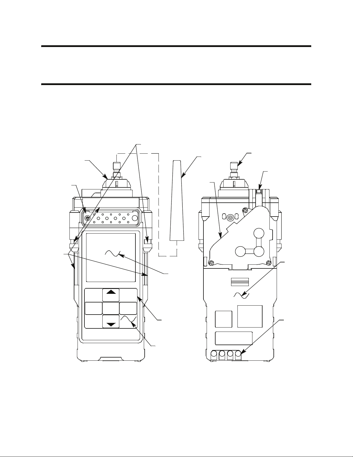
Instrument Description
The instrument includes the case, sensors, LCD, control buttons, printed
circuit boards, alarm LED’s, infrared communication port, buzzer, vibrator,
batteries, pump, flow chamber, and inlet filter holder.
Wrist Strap Installation Feature
Inlet Filter
Holder
Tapered
Rubber
Nozzle
Inlet Fitting
Exhaust
Buzzer
Opening
Alarm
LED
Arrays
DISPLAY
(ADJ)
AIR
POWER
ENTER
(SHIFT)
RESET
SI LENCE
Chamber
LCD
Control
Buttons
IR Port
(behind
button label)
Flow
Battery
Cov er
(alkaline
version)
Charging
Contacts
Figure 1: Components of the GX-2012, Front & Back
GX-2012 Operator’s Manual Overview • 5
Page 14
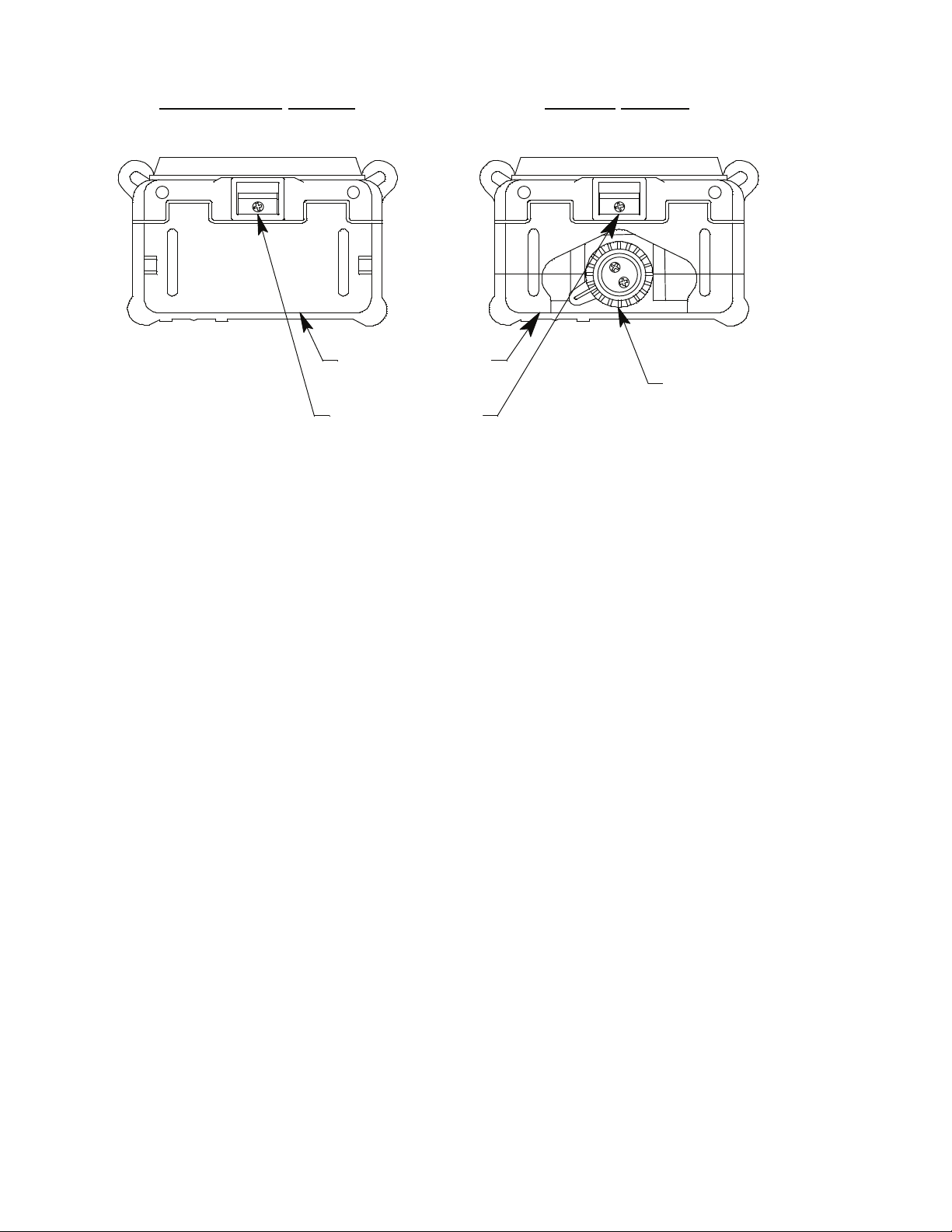
Rechargeable Version
Battery Pack
Battery Pack
Release Latch
Figure 2: Components of the GX-2012, Bottom
Alkaline
Version
Battery Cover
Release Knob
Case
The Model GX-2012’s sturdy, high-impact plastic case is radio frequency
(RF) resistant and is suitable for use in many environmental conditions,
indoors and out. The case is dust proof and weather resistant. A rubber layer
on the outside of the case protects it from scratches and impact damage.
A clear plastic window through which the LCD can be viewed is located on
the front of the case. Four brass charging contacts that are used when the GX2012 is placed in the charging station are on the back of the case. Both the
rechargeable and alkaline versions include a removable battery pack. The
battery pack release latch is on the bottom. The alkaline battery version also
includes a battery cover release knob. The battery pack and flow chamber are
located on the back of the GX-2012. The inlet filter holder is located on the
top of the GX-2012 case.
Sensors
The GX-2012 uses up to five sensors to monitor combustible gas, oxygen
), carbon monoxide (CO), and hydrogen sulfide (H2S) simultaneously.
(O
2
The sensors are located inside the GX-2012 and are held in their sockets by
the flow chamber. The sensors use different detection principles, as described
below.
6 • Instrument Description GX-2012 Operator’s Manual
Page 15

Combustible Gas Sensors
% LEL Sensor (NC-6264A)
The % LEL sensor detects combustible gas in the % LEL range. It uses a
catalytic element for detection. The reaction of gas with oxygen on the
catalyst causes a change in the resistance of the element which affects the
current flowing through it. The current is amplified by the GX-2012’s
circuitry, converted to a measurement of combustible gas concentration, and
displayed on the LCD.
NOTE: The %LEL sensor cannot be used in instruments intended for Leak
Check Mode operation.
LEL/ppm Sensor (NC-6264ALB)
The LEL/ppm combustible sensor is a specialized version of the % LEL
sensor. It is used instead of the % LEL sensor in instruments that are intended
for use in Leak Check Mode. The LEL/ppm sensor can also be used for
detection in Normal Mode.
%Volume Sensor (TE-7561)
The % volume sensor detects combustible gas in the % volume range. It uses
a thermal conductivity (TC) element for detection. The presence of
combustible gas cools the element causing a change in the resistance of the
element which affects the current flowing through it. The current is amplified
by the GX-2012’s circuitry, converted to a measurement of combustible gas
concentration, and displayed on the LCD.
Oxygen Sensor
The O2 sensor is a galvanic type of sensor. A membrane covers the cell and
allows gas to diffuse into the cell at a rate proportional to the partial pressure
of oxygen. The oxygen reacts in the cell and produces a voltage proportional
to the concentration of oxygen. The voltage is measured by the GX-2012’s
circuitry, converted to a measurement of gas concentration, and displayed on
the LCD.
CO and H2S Sensors
The CO and H2S sensors are electrochemical cells that consist of two
precious metal electrodes in a dilute acid electrolyte. A gas permeable
membrane covers the sensor face and allows gas to diffuse into the
electrolyte. The gas reacts in the sensor and produces a current proportional
to the concentration of the target gas. The current is amplified by the GX2012’s circuitry, converted to a measurement of gas concentration, and
displayed on the LCD.
GX-2012 Operator’s Manual Instrument Description • 7
Page 16
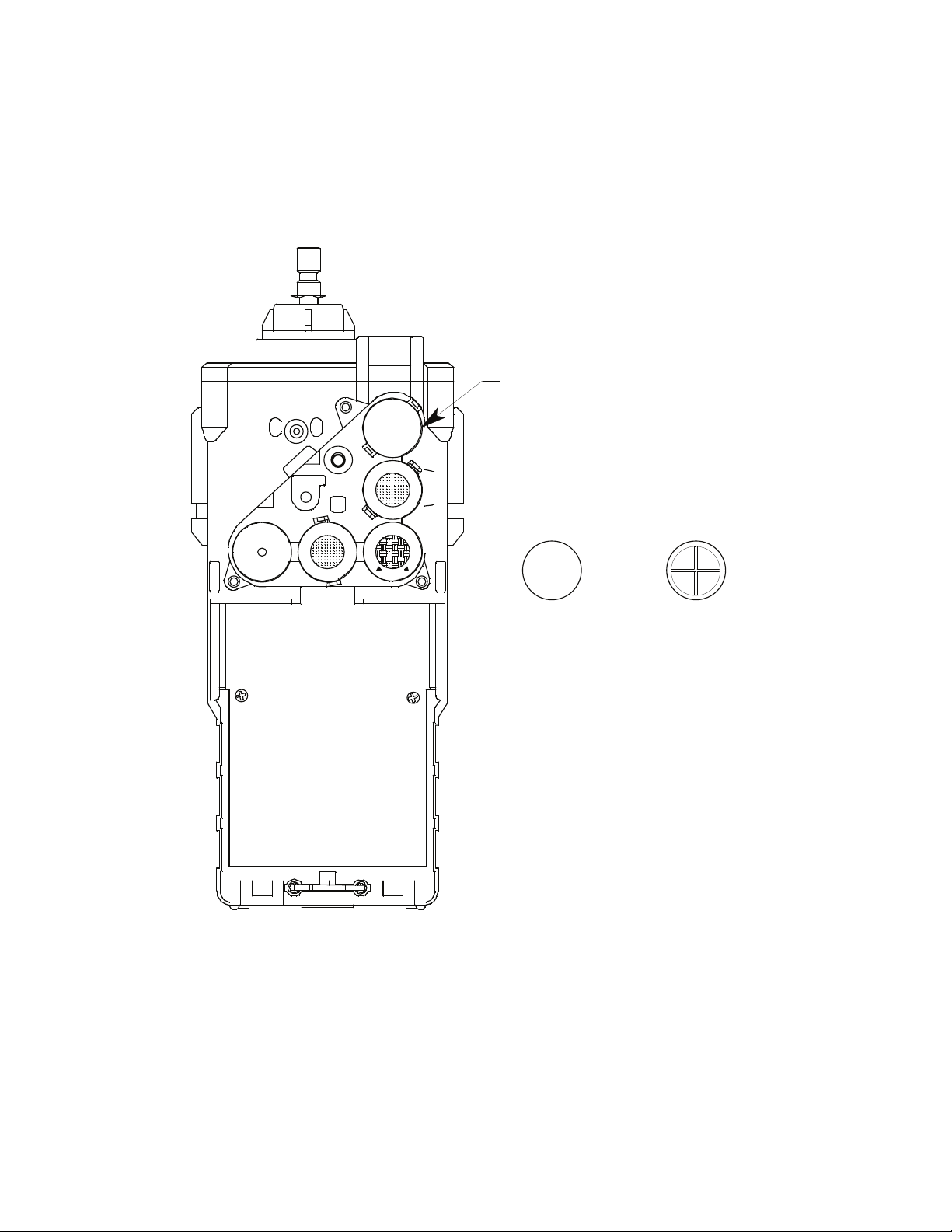
Dummy Sensors
Any unit that has less than 5 sensors will have a dummy sensor installed in
one or more sensor positions. Dummy sensors are factory installed. The flat
top of the dummy sensor should face up and the bottom hollow side should
face down. The unit shown below is a standard 4-sensor unit for LEL/O
S/CO and has a dummy sensor installed in the %volume combustible
H
2
/
2
sensor position.
Dummy Sensor
Top Flat
Side
Figure 3: Dummy Sensor
Bottom
Hollow Side
LCD
A digital LCD (liquid crystal display) is visible through a clear plastic
window on the front of the case. The LCD display simultaneously shows the
gas reading for all installed sensors. The display also shows information for
each of the GX-2012’s program modes.
8 • Instrument Description GX-2012 Operator’s Manual
Page 17

Control Buttons
Five control buttons are located below the LCD. They are arranged around a
central button, the POWER ENTER button. The DISPLAY (ADJ) button is
on the left, the RESET SILENCE button on the right, the AIRS button on
the top, and the (SHIFT)T is on the bottom.
Table 2: GX-2012 Control Button Functions
Button Function(s)
POWER ENTER • turns the GX-2012 on and off.
• used during setup and calibration.
RESET SILENCE silences and resets audible alarm if the GX-2012 is programmed
for latching alarms and the alarm silence option is on
DISPLAY (ADJ) • activates Display Mode
• enters instructions into the GX-2012’s microprocessor
AIRS • activates the demand-zero function (automatically adjusts the
GX-2012 in fresh-air conditions)
• scrolls through the display and settings modes
1
(SHIFT)T • scrolls through the display and settings modes
• enters instructions into the GX-2012’s microprocessor
1 The GX-2012’s alarms are user-adjustable. See “Chapter 6: Maintenance Mode” on page 100.
Printed Circuit Boards
The GX-2012 printed circuit boards analyze, record, control, store, and
display the information collected. The circuit boards are located inside the
case. They are not user serviceable.
Alarm LED Arrays
Three red alarm LED (light emitting diode) arrays are visible through frosted
plastic lenses in the case. One is on the top front, one on the left side, and one
on the right side. The alarm LED arrays alert you to gas, low battery, and
failure alarms.
Infrared Communications Port
An infrared (IR) communications port is located just below the RESET
SILENCE button. The signal goes through the control button material. The
data transmitted through the port is in standard IrDA protocol. A computer’s
infrared port or an IrDA/USB cable connected to a computer’s USB port can
be used to download data saved by the GX-2012 to a computer using the GX2012 Data Logger Management Program. See the GX-2012 Data Logger
Management Program operator’s manual for data logging and downloading
instructions.
GX-2012 Operator’s Manual Instrument Description • 9
Page 18

Buzzer
One solid-state electronic buzzer is located inside the case. Holes on the top
front of the case allow the sound to exit the case. The buzzer sounds for gas
alarms, malfunctions, low battery voltage, and as an indicator during use of
the GX-2012’s many display and adjustment options.
Vibrator
A vibrating motor inside the GX-2012 case vibrates for gas alarms, unit
malfunctions, and as an indicator during normal use of the various modes of
the GX-2012.
Batteries
Three AA-size alkaline batteries (standard) or an optional rechargeable
lithium ion battery pack (3.7 VDC) power the GX-2012. Instrument run time
is dependent upon battery type. At 25°C the alkaline batteries last up to 15
hours and the lithium ion battery pack lasts up to 10 hours. The battery icon
in the upper right of the LCD shows remaining battery life.
When the GX-2012 detects a low battery voltage, a low battery warning is
activated. When battery voltage is too low for normal operation, the GX2012 sounds a dead battery alarm.
The alkaline batteries can be replaced by removing the battery cover on the
back of the case. The lithium ion pack can be replaced by removing the entire
battery pack. Push the battery pack latch on the bottom of the unit toward the
front of the unit to release the pack.
The lithium ion battery pack can be recharged by placing the GX-2012 in its
optional battery charging station or by placing the battery pack in the
charging station.
NOTE: Use of batteries or battery chargers not specified by RKI
Instruments, Inc. will void the CSA classification and may void the
warranty. See “Replacing or Recharging the Batteries” on page 146.
WARNING: To prevent ignition of a hazardous atmosphere, batteries
must only be changed or charged in an area known to be
nonhazardous.
10 • Instrument Descript ion GX-2012 Operator’s Manual
Page 19

Pump
A diaphragm pump inside the GX-2012 draws the sample to the sensors. It
can draw sample from as far as 50 feet from the GX-2012. The pump is not
user serviceable.
CAUTION: Sample hose lengths of more than 50 feet are not recommended
for the GX-2012 because of flow rate reduction.
Flow Chamber
The flow chamber is on the back of the GX-2012 and is held in place by three
phillips screws. The flow chamber seals to the rubber sensor gasket which
seals to the sensor faces inside the GX-2012 and routes flow from the pump
to the sensors and to the exhaust port (also a part of the flow chamber).
Sensors and Filters
The sensors are located underneath the flow chamber and are only accessible
if you remove the flow chamber and the sensor gasket.
An H
the %LEL sensor. This filter darkens as it absorbs H
S removal filter disk is placed into a recess in the sensor gasket over
2
S and should be
2
replaced when it is a dark brown color. Check the condition of this filter
quarterly.
A charcoal filter is placed into a recess in the sensor gasket over the CO
sensor. The charcoal filter is black, has a woven texture, and is impregnated
with an H
H
S and certain hydrocarbon gases. The charcoal filter disk scrubs these
2
S absorbing material. The CO sensor will respond if exposed to
2
gases out of the sample to avoid false CO readings. If false or elevated CO
readings are noticed, especially in the presence of H
S, change the charcoal
2
filter.
Inlet Filter Holder
The filter holder is a clear plastic dome shaped piece on the top of the case. A
male quick connect fitting is located on the inlet filter holder. This is the GX2012’s inlet fitting. A cotton dust filter is inside the filter holder. The filter
holder may be removed by turning it counterclockwise and pulling it away
from the case. Two flat membrane disk hydrophobic filters, a wire mesh disk,
and a rubber filter retaining gasket are held in place by the filter holder and
are located in the bottom of the case chamber where the filter holder is
installed.
GX-2012 Operator’s Manual Instrument Description • 11
Page 20
Standard Accessories
The standard accessories include the tapered rubber nozzle, belt clip, sample
hose, and 10 inch probe. An optional bar hole probe is also available and is
described at the end of this section.
Tapered Rubber Nozzle
A cone shaped 4 inch long rubber nozzle is included with the GX-2012 as
standard. It can be installed on the inlet fitting by pushing the larger end over
it. The smaller end can be inserted through a hole in a wall or some other
access to an enclosed area to sample the environment.
Belt Clip
A belt clip can be mounted to the back of the case using 3 phillips head
screws. The belt clip allows the GX-2012 to be securely attached to a belt.
Wrist Strap
A wrist strap is included with the GX-2012 and can be attached to the right or
left wrist strap installation feature.
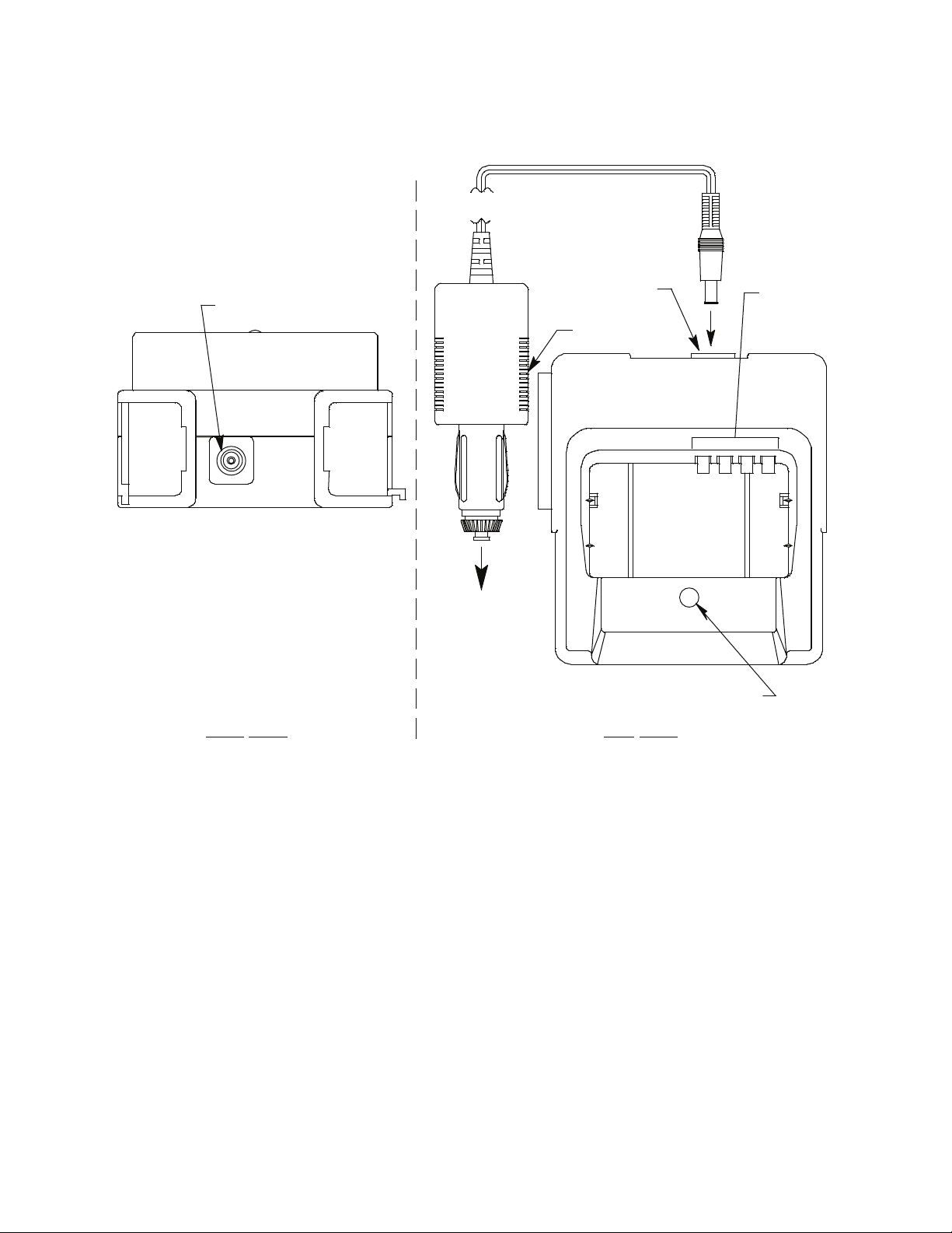
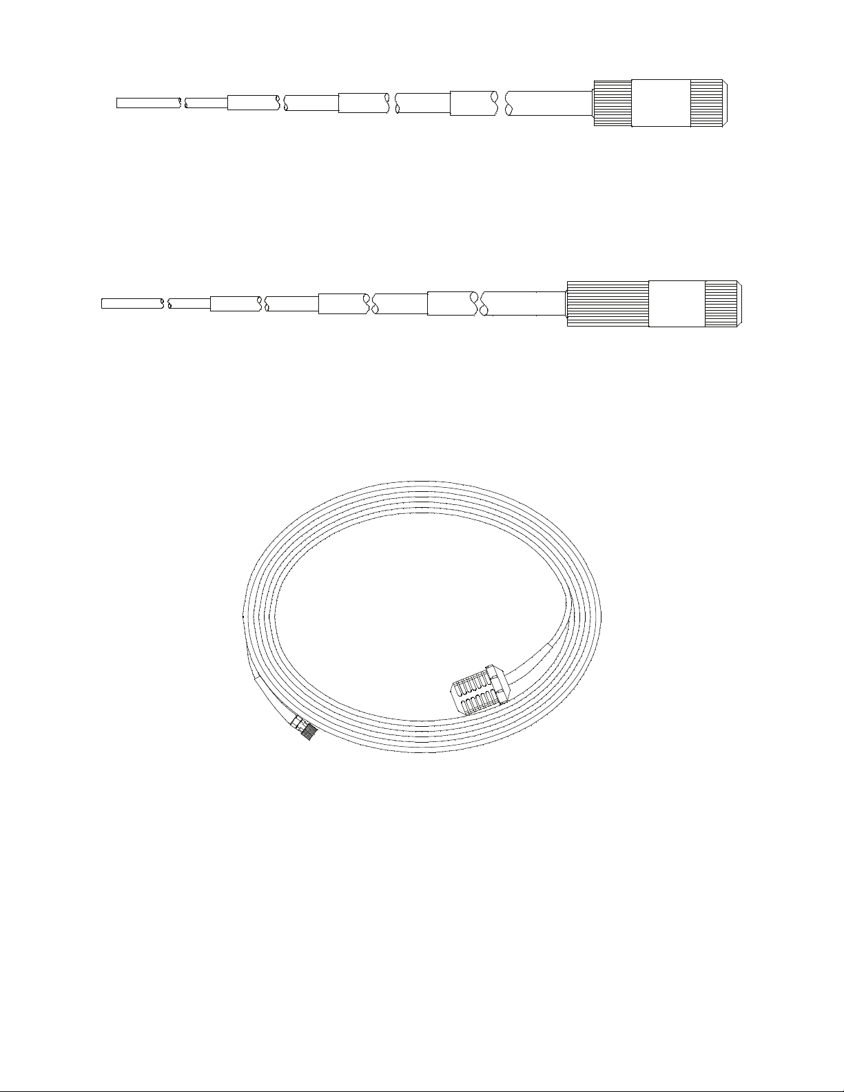
Sample Hose & 10 Inch Probe
A 10 foot sample hose and a 10 inch probe are included as standard with the
GX-2012. When desired, the rubber nozzle may be removed and the sample
hose and 10 inch probe may be connected to the inlet fitting. Sample hose
lengths are available from 10 feet to 50 feet (see “Parts List” on page 158).
The quick connect end of the sample hose connects to the inlet fitting of the
GX-2012 and the probe screws onto the end of the hose with the threaded
fitting.
CAUTION: Sample hose lengths of more than 50 feet are not recommended
for the GX-2012 because of flow rate reduction.
Sample Hose
Probe
Figure 4: Sample Hose and Probe
12 • Standard Accessories GX-2012 Operator’s Manual
Page 21

Optional Accessories
Several optional accessories are available for the GX-2012. They include a
rechargeable lithium ion battery pack, charging stations, various special
probes, a purge tee fitting, and a dilution fitting. The most commonly used
optional accessories are described below. Detailed instructions regarding the
use of these and other available accessories are included in other parts of this
manual. Data logging accessories are briefly described in “Data Logging” on
page 56.
Rechargeable Lithium Ion Battery Pack
A rechargeable lithium ion battery pack is available for the GX-2012. A fully
charged battery pack will power the GX-2012 for 10 hours. The batteries will
last for a minimum of 500 charge cycles. See the “Parts List” on page 158 for
ordering information.
Charging Stations
The GX-2012 lithium ion battery pack is charged with the GX-2012 charging
station. Two battery charging stations are available for the GX-2012, the
standard AC charging station, and a DC charging station with a vehicle plug
adapter.
GX-2012 Operator’s Manual Optional Accessories • 13
Page 22
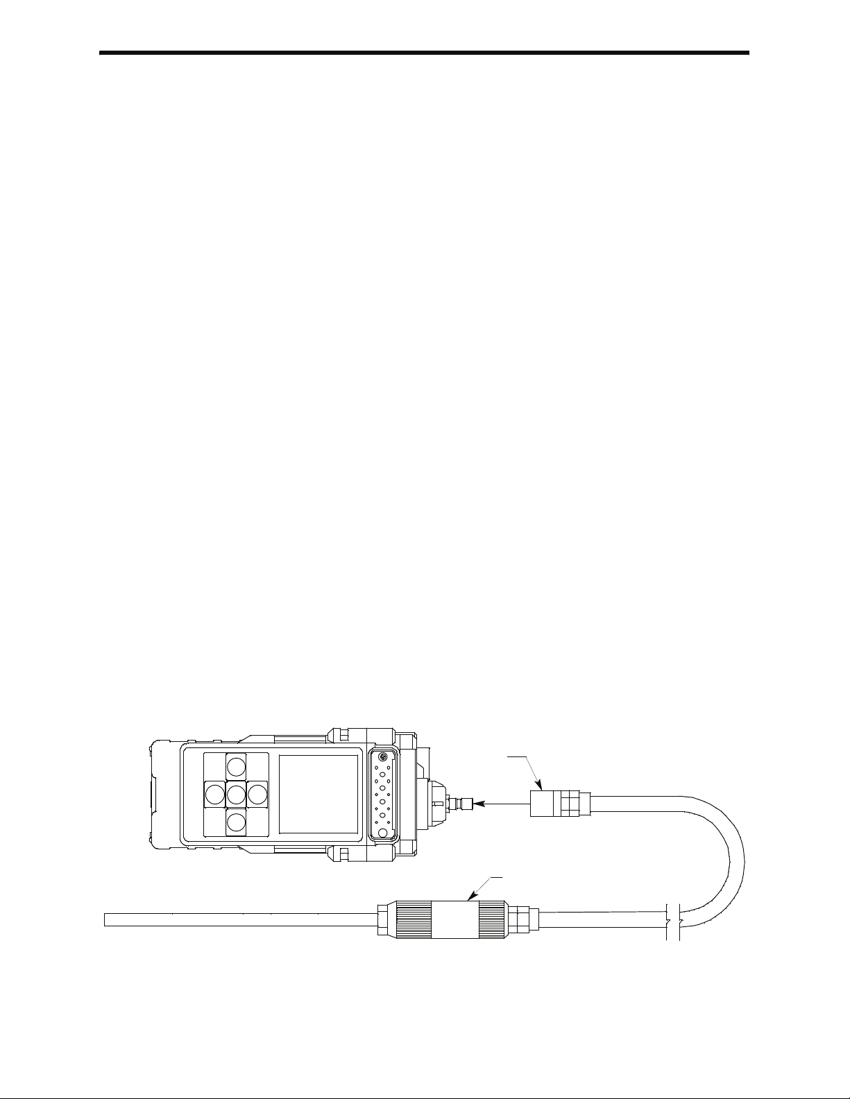
AC Powered Charging Station
The standard AC powered charging station consists of an instrument
charging base and an AC adapter. The AC adapter plugs into a 115 VAC wall
outlet and connects to the charging station with a jack on the end of a five
foot DC output cable. The AC adapter will also work for 100 VAC or 220
VAC if an appropriate plug adapter is provided. The AC charging station is
shown below in Figure 5.
AC Adapter
Adapter Jack
Figure 5: GX-2012 AC Powered Charging Station
To AC
Outlet
Charge LED
Adapter Jack
ViewRear View
Top
Charging
Contacts
14 • Optional Accessorie s GX-2012 Operator’s Manual
Page 23
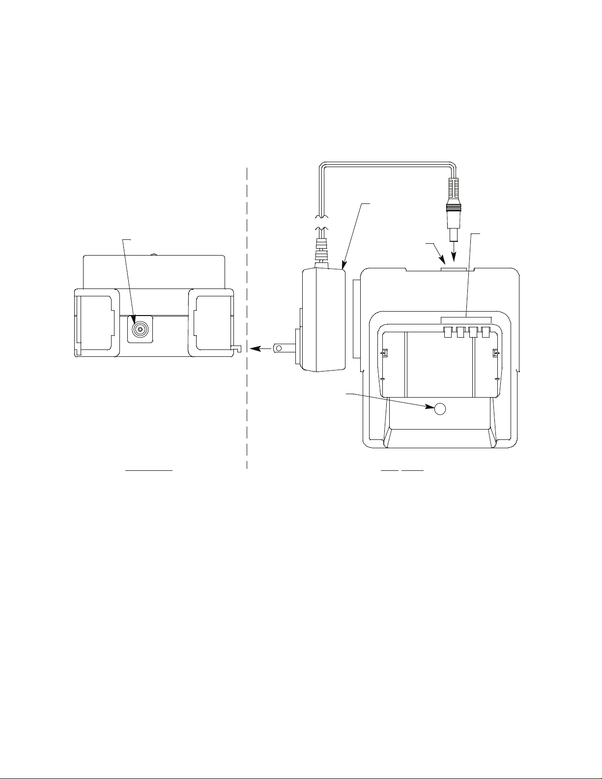
DC Powered Charging Station
An optional DC powered charging station is available with a vehicle plug 12
VDC adapter. It uses the same charging base as the AC charging station but
comes with a velcro strap to secure the GX-2012 in the charging base.
Adapter Jack
Rear View
To Vehicle
12 VDC
Power Socket
Adapter Jack
Vehicle Plug
Top
Chargi ng
Contacts
Charge LED
View
Figure 6: GX-2012 DC Powered Charging Station
GX-2012 Operator’s Manual Optional Accessories • 15
Page 24
Optional Probes
Various optional probes designed for specific applications are available for
the GX-2012. They include the following:
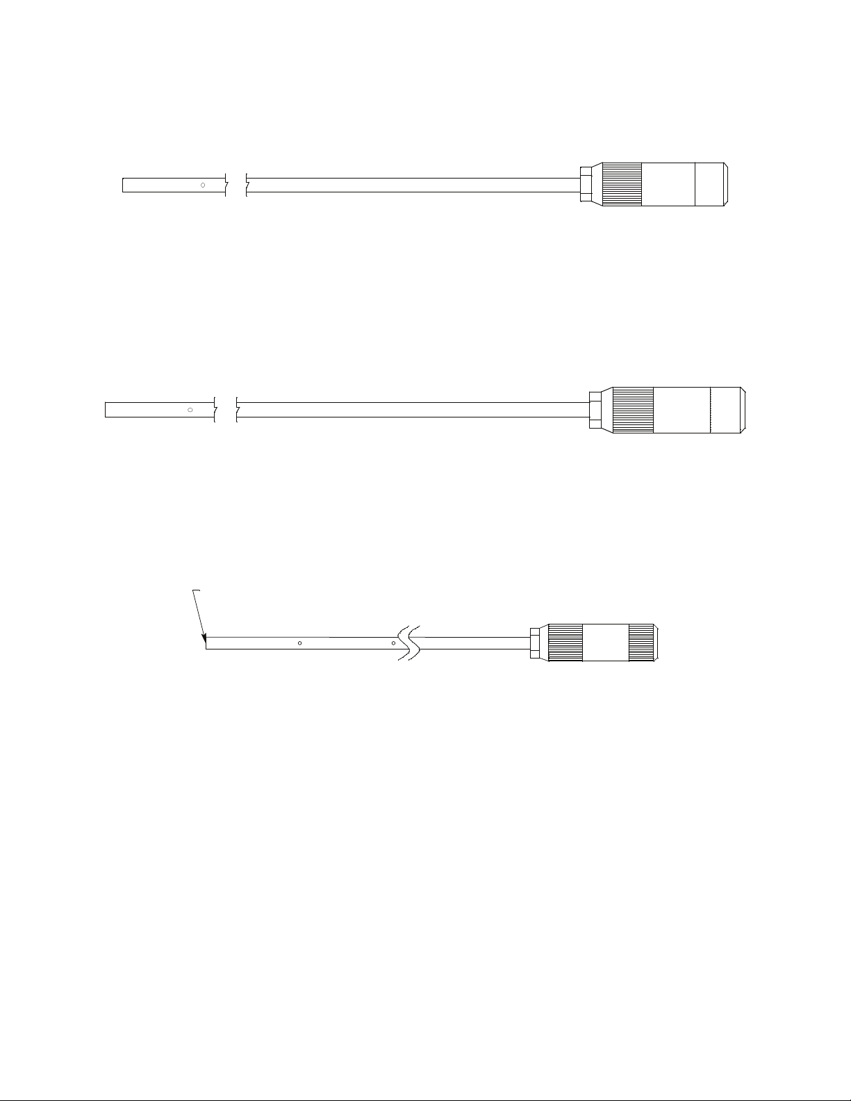
• 30 inch aluminum probe
Figure 7: 30 Inch Aluminum Probe
This probe is designed for applications where it is necessary to put the
probe tip in areas that are out of reach with the standard probe. A small
breather hole near the end of the probe tube prevents interruption of
sampling and a low flow alarm if the probe tip is blocked.
• 30 inch stainless steel probe
Figure 8: 30 Inch Stainless Steel Probe
This probe is physically the same as the 30 inch aluminum probe and is
intended for applications where a high level of corrosion resistance is
required in the long probe tube.
• Barhole probe
End Plugged
Figure 9: Barhole Probe
An optional bar hole probe is available for the GX-2012. It is designed to
be used when the GX-2012 is operated in Bar Hole Mode to check bar
holes when tracking down underground gas pipe leaks (see “Chapter 4:
Using the GX-2012 in Bar Hole Mode” on page 73). The bar hole probe
has the same handle as the standard probe, but has a 30 inch fiberglass
tube instead of the standard tube. Four holes are drilled through the 30
inch tube’s wall near the end and the end is plugged so that debris from
the barhole cannot be drawn into the tube. The sample is drawn through
the drilled holes in the tube wall.
16 • Optional Accessorie s GX-2012 Operator’s Manual
Page 25
• 32 inch telescoping probe with dust filter
Figure 10: 32 Inch Telescoping Probe with Dust Filter
This probe is designed for use where it is necessary to put the probe tip in
areas not accessible with the 10 inch probe with dust filter and
applications where the probe tube must be collapsible for storage.
• 7 foot telescoping probe with dust filter
Figure 11: 7 Foot Telescoping Probe with Dust Filter
This probe is designed for use where it is necessary to put the probe tip in
areas not accessible with the 32 inch telescoping probe with dust filter and
applications where the probe tube must be collapsible for storage.
• 8 meter hose with floating head
This probe is designed to be used in a tank or a well that may have water
or some other liquid at the bottom. As you lower the probe down, if it hits
water, it will float and continue to monitor the area.
See the “Parts List” on page 158 for probe ordering information.
GX-2012 Operator’s Manual Optional Accessories • 17
Page 26
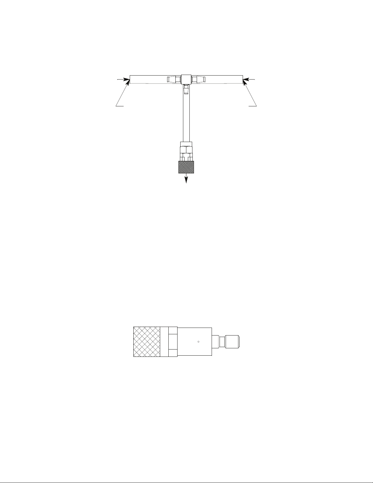
Purge Tee Fitting
The 17-4430RK-01 purge fitting is used to detect gas levels in a pressurized
gas stream from a pipeline or vessel being purged. The sample port of the
purge fitting is inserted into the flowing gas, and the vent port will allow any
excess gas to release to the atmosphere to avoid damage to pump or sensors.
Pressurized
Stream
Sample Port
GX-2012 Inlet
Figure 12: Purge Tee Fitting
Vent Port
Excess
Pressurized
Sample
External Dilution Fitting
An external dilution fitting is available for the GX-2012. It is a 1:1 dilution
fitting and is designed to mate with the inlet fitting and accept a sample hose
or probe. The fittings are made with brass and nickel plated brass and are
appropriate for use with the four standard gases. The dilution fitting is
normally used when it is necessary to introduce air into a sample that has no
oxygen or a very low level of oxygen, such as a nitrogen purged sample. It
can also be used when one of the target gas levels in the sample area will
likely be present in a concentration above the detection range for that gas.
Since the fittings partially consist of unplated brass, they are not appropriate
for detection of elevated levels of H
S.
2
Figure 13: Dilution Fitting
18 • Optional Accessorie s GX-2012 Operator’s Manual
Page 27

Chapter 3: Using the GX-2012 in Normal Mode
Overview
This chapter explains how to operate the GX-2012 in Normal Mode. Normal
Mode is used to perform confined space entry monitoring or general area
monitoring. While in Normal Mode, Display Mode and Calibration Mode are
accessible.
If a standard version of the GX-2012 is ordered, it is shipped with Bar Hole
Mode disabled so that the instrument only runs in Normal Mode when turned
on.
Start Up, Normal Mode
This section explains how to start up the GX-2012 in Normal Mode, get it
ready for operation, and turn it off.
NOTE: The screens illustrated in this section are for a 4-gas unit that has the
% LEL range for the combustible gas channel. The screens
displayed by your GX-2012 may be slightly different.
Turning On the GX-2012, Normal Mode Only
The following description of the GX-2012 start up sequence assumes that the
following items in Maintenance Mode are turned on: LNCH BRK, ID DISP,
CL RMNDR, and BP RMNDR. If any of these items is turned off, then the
corresponding screen will not appear. This description also assumes that Bar
Hole Mode is not active.
1. Connect the tapered rubber nozzle or the sample hose to the GX-2012’s
quick connect inlet fitting.
2. If a sample hose is used, screw the probe onto the sample hose’s threaded
fitting.
3. Press and briefly hold down the POWER ENTER button. Release the
button when you hear a beep.
GX-2012 Operator’s Manual Overview • 19
Page 28
4. If LNCH BRK is turned on, the Resume Datalog Screen displays.
rESU
4
RESUME
• Press and release the POWER ENTER button to continue
accumulating time-weighted average (TWA), PEAK readings, and
time in operation from the last time the GX-2012 was used. The
short-term exposure limit [STEL] reading is reset each time the GX2012 is turned on.
• Press and release the DISPLAY(ADJ) button to reset the
accumulation of these measurements.
If you do not press the POWER ENTER or DISPLAY(ADJ) button
within 5 seconds, the GX-2012 automatically resumes accumulating the
TWA, PEAK readings, and time in operation.
5. If CL RMNDR is turned on (factory setting), the screen that appears next
depends on how CL EXPRD is set in the Maintenance Mode Menu
(page 131).
• If the unit is due for calibration and CL EXPRD is set to CONFIRM
(factory setting), then the following screen displays.
CAL
C--LIMIT
The alarm LED’s and buzzer will pulse several times. After this,
press the RESET SILENCE button until you hear a beep to continue.
20 • Start Up, Normal Mode GX-2012 Operator’s Manual
Page 29
• If the unit is due for calibration and CL EXPRD is set to NOT USE,
then the following screen displays.
FAIL
C--LIMIT
The GX-2012 cannot be used until a calibration has been performed
either by selecting AUTO CAL or ONE CAL in the Maintenance
Mode menu. See “Calibrating Using Auto Calibration” on page 105
or “Calibrating Using Single Calibration” on page 108 for calibration
instructions.
• If calibration is not due or CL EXPRD is set to NO EFFECT, then
the following screen appears for a few seconds indicating when the
next calibration is due.
2011
9
30
69d
NEXT CAL
6. If BP RMNDR is turned on (factory setting is OFF), the screen that
appears next depends on how BP EXPRD is set in the Maintenance
Mode Menu (page 131).
• If the unit is due for a bump test and BP EXPRD is set to CONFIRM
(factory setting), then the following screen displays.
tESt
B--LIMIT
The alarm LED’s and buzzer will pulse several times. After this,
press the RESET SILENCE button until you hear a beep to continue.
GX-2012 Operator’s Manual Start Up, Normal Mode • 21
Page 30
• If the unit is due for a bump test and BP EXPRD is set to NOT USE,
then the following screen displays.
FAIL
B--LIMIT
The GX-2012 cannot be used until a bump test has been performed
by selecting BUMP in the Maintenance Mode menu. See
“Performing a Bump Test” on page 111 for bump testing instructions.
• If a bump test is not due or BP EXPRD is set to NO EFFECT, then
the following screen appears for a few seconds indicating when the
next bump test is due.
2011
9
30
10d
NEXTBUMP
NOTE: If both CL RMNDR and BP RMNDR are turned off, a WARM UP
screen will display before the warm up sequence continues.
22 • Start Up, Normal Mode GX-2012 Operator’s Manual
Page 31
7. If ID DISP is turned on (see page 135), the User ID Screen displays for a
few seconds and then the Station ID Screen displays for a few seconds.
U Id
- - - - - - - -
S Id
- - - - - - - -
8. The Date/Time Screen appears for a few seconds.
2011
8
31
22:39
DATE
This screen displays the current year, month, day, and time.
GX-2012 Operator’s Manual Start Up, Normal Mode • 23
Page 32

9. The Battery Level and Alarm Pattern Screen appears next.
bAtt
3.7
AL-H V
AL -- H indicates latching (hold) alarms and AL -- A indicates selfresetting (automatic) alarms. The number shown indicates the voltage of
the batteries. A fully charged lithium ion battery pack will display 3.7 V.
If the unit is powered by alkaline (dry cell) batteries, a “D” will appear in
front of the “V” in the lower right corner.
bAtt
3.7
AL-H D: V
10. The display then indicates the following items for about a second each:
• Full scale values for all channels
• Warning setpoint (low gas alarm) for all channels
• Alarm setpoint (high gas alarm) for all channels
• STEL alarm setpoint for the CO and H
• TWA alarm setpoint for the CO and H
NOTE: If the combustible channel is factory set as %volume only, all gas
alarms are turned off. You must press and release the RESET
SILENCE button at the warning, alarm, STEL, and TWA screens to
acknowledge that there are no gas alarms. The warm up will not
proceed until you do so.
S channels
2
S channels
2
If the combustible channel is set up as %volume only using the HC
Range Screen in Display Mode, it will automatically revert to
Autoranging when it is turned off and on again and the no alarm
acknowledgement screen will not appear.
24 • Start Up, Normal Mode GX-2012 Operator’s Manual
Page 33

11. If the GX-2012 experiences a sensor failure during start up, a screen
indicating which sensor failed displays. In the example below, the CO
sensor has failed.
FAIL
CO
SENSOR
If you wish to continue, press and release the RESET SILENCE button to
acknowledge the failure. The gas reading for the failed sensor will be
replaced by “---”. Replace the failed sensor as soon as possible.
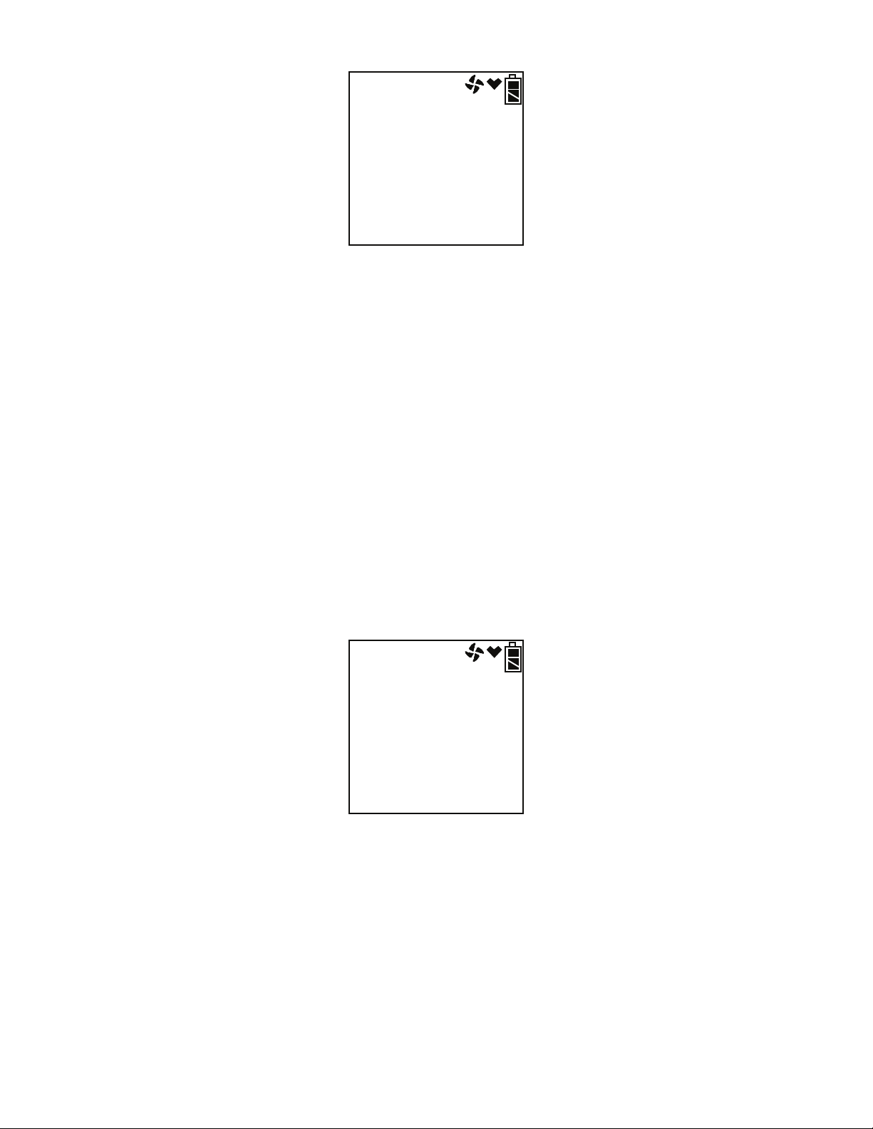
12. The GX-2012 is now operating in Normal Mode and monitoring for gas
in Measuring Mode. The Normal Operation Screen appears.
ppm
CH4
O2
CO
H2S
22:37
0
20.9
0
0.0
%LEL
%
ppm
ppm
The concentrations of the target gases are displayed along with the time and
battery charge level. The heart symbol displayed just to the left of the battery
charge level flashes while the instrument is functioning properly. If it
disappears or is steadily on, the unit is experiencing a microprocessor error.
The fan symbol just to the left of the heart symbol spins while the pump is
operating.
Turning On the GX-2012 in Normal Mode
With All Modes Active
If the L./B. MODE item in Maintenance Mode is set to LC, bH, or LC bH
(see “Updating the Leak Check/Bar Hole Mode Setting” on page 137), then
the user must select Normal Mode during the start up sequence to operate in
Normal Mode. The standard factory setting for L./B. MODE is OFF. See
“Chapter 4: Using the GX-2012 in Bar Hole Mode” on page 73 for a
description of Bar Hole Mode or “Chapter 5: Using the GX-2012 in Leak
Check Mode” on page 84 for a description of Leak Check Mode.
The following description of the GX-2012 start up sequence assumes that the
following menu items in Maintenance Mode are turned on: LNCH BRK, ID
GX-2012 Operator’s Manual Start Up, Normal Mode • 25
Page 34

DISP, CL RMNDR, and BP RMNDR. If any of these items is turned off,
then the corresponding screen will not appear. It also assumes that the L./B.
MODE menu item in Maintenance Mode is set to LC bH. If L./B. MODE is
set to LC, the Bar Hole Mode Select Screen will not appear. If L./B. MODE
is set to bH, the Leak Check Mode Select Screen will not appear.
1. Connect the tapered rubber nozzle or the sample hose to the
GX-2012’s quick connect inlet fitting.
2. If a sample hose is used, screw the probe onto the sample hose’s threaded
fitting.
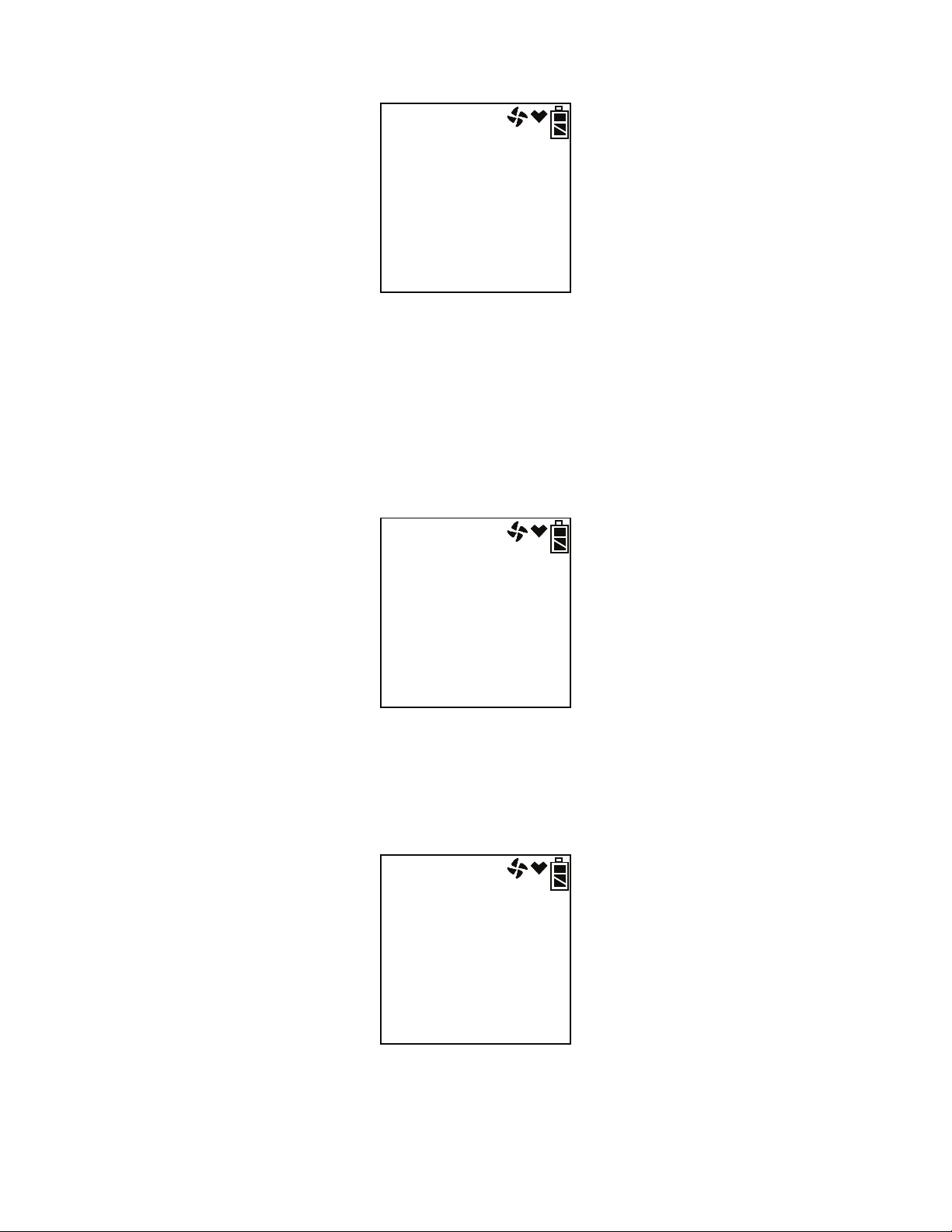
3. Press and briefly hold down the POWER ENTER button. The Normal
Mode Select Screen displays.
vol%
CH4
O2
CO
H2S
NORMAL ?
0
20.9
0
0.0
%LEL
%
ppm
ppm
4. You can use the AIRS button to scroll to the Bar Hole Mode Select
Screen.
BAR HOLE MODE
CH4
O2
0
20.9
30
B.H. MODE?
vol%
%LEL
%
sec
5. Press the AIRS button again to display the Leak Check Mode Select
Screen.
LEAK CK MODE
CH4
L.C. MODE?
0
5000
ppm
ppm
LEAK CK MODE
CH4
CO
L.C. MODE?
0
0
5000
ppm
ppm
ppm
CO DISP OFF CO DISP On
26 • Start Up, Normal Mode GX-2012 Operator’s Manual
Page 35

NOTE: If the CO DISP parameter in Maintenance Mode is set to On, the
CO channel will appear in Leak Check Mode. If the CO DISP
parameter is set to OFF (factory setting), the CO channel will not
appear in Leak Check Mode. See “Chapter 5: Using the GX-2012 in
Leak Check Mode” on page 84 for more information.
You can scroll up or down through these screens using the AIRS or
(SHIFT)T buttons.
6. With the Normal Mode Select Screen displayed, press and release the
POWER ENTER button and continue with the startup sequence as
described in the previous section, “Turning On the GX-2012, Normal
Mode Only”, from step 4 on page 20 on.
NOTE: If no button is pressed for 20 seconds, the unit will proceed into
whichever mode is displayed.
7. To exit Normal Mode and return to the Mode Select Screen, press and
hold the (SHIFT)T button for 5 seconds while in the Normal Operation
Screen.
Performing a Fresh Air Adjustment, Normal Mode
Before using the GX-2012, it is recommended to set the fresh air readings for
the target gases by performing a fresh air adjustment. This will set the
combustible gas, CO, and H
20.9%.
1. Find a fresh-air environment. This is an environment free of toxic or
combustible gases and of normal oxygen content (20.9%).
2. Turn on the unit as described above in “Turning On the GX-2012,
Normal Mode Only” or “Turning On the GX-2012 in Normal Mode With
All Modes Active”.
3. Press and hold the AIRS button. The display prompts you to hold the
AIRS button.
S channels to zero and the OXY channel to
2
AIr
CAL
HOLD AIR
4. Continue to hold the AIRS button until the display prompts you to
release the AIRS button. The GX-2012 will count down from 8 on an
autoranging combustible gas channel as it sets the fresh air reading for all
GX-2012 Operator’s Manual Start Up, Normal Mode • 27
Page 36

channels. Once the countdown has finished, start up is complete and the
unit is ready for monitoring.
Turning Off the GX-2012, Normal Mode
1. Press and hold the POWER ENTER button.
2. The buzzer will pulse for about three seconds and TURN OFF will be
displayed along the bottom of the screen.
3. Release the button when TURN OFF disappears.
Measuring Mode, Normal
Operation
The GX-2012 has three operating modes within Normal Mode: Measuring
Mode, Display Mode, and Calibration Mode. This section describes using the
GX-2012 in Measuring Mode during normal operation.
In Measuring Mode the GX-2012 continuously monitors the sampled
atmosphere and displays the gas concentrations present for its target gases. In
a low-light environment, press and release any button to turn on the display
backlight. See “Updating the LCD Back Light Time Setting” on page 135 to
program backlight duration. If the BEEP. SET menu item in Maintenance
Mode is turned on, the GX-2012 beeps once every 5 minutes to confirm that
it’s operating. See “Updating the Confirmation Beep Setting” on page 129 for
instructions to update the setting.
Monitoring an Area
1. Start up the GX-2012 as described above in “Start Up, Normal Mode” on
page 19 or “Turning On the GX-2012 in Normal Mode With All Modes
Active”. It is now in Measuring Mode.
2. Take the GX-2012 to the monitoring area.
If the tapered rubber nozzle is used, put the nozzle tip in the area to be
monitored.
If the hose and probe is used, put the probe tip in the area to be
monitored.
3. Wait 10 - 15 seconds and observe the display for gas readings. If a
reading is observed, allow the reading to stabilize to determine the gas
concentrations present.
28 • Mea suring Mode, Normal Operation GX-2012 Operator’s Manual
Page 37

NOTE: Response time increases with the length of the sample hose. Long
sample hoses will require more time to show a response at the GX-
2012. The maximum sample hose length recommended for the GX2012 is 50 feet. Consult RKI Instruments, Inc. for longer sample
hose lengths.
4. If a gas alarm occurs, take appropriate action. See “Responding to
Alarms” on page 39.
Using Optional Probes and Fittings
This section describes how to use the 8 meter hose with floating head and the
purge tee fitting.
Using the 8 Meter Hose with Floating Head
This probe is designed to be used in a tank or a well that may have water or
some other liquid at the bottom. To use the 8 meter hose with floating probe:
1. Start up the GX-2012 as described in “Start Up, Normal Mode” on
page 19.
2. Connect the 8 meter hose with floating probe to the GX-2012’s quick
connect inlet fitting.
3. Slowly lower the probe into the area you wish to monitor. If the probe
hits water, it will float and continue to monitor the area.
Figure 14: 8 Meter Hose with Floating Head
Using the Purge Tee Fitting
The purge fitting is used to detect gas levels in a pressurized gas stream from
a pipeline or vessel being purged.
1. Start up the GX-2012 as described in “Start Up, Normal Mode” on
GX-2012 Operator’s Manual Measuring Mode, Normal Operation • 29
Page 38

page 19.
2. Connect the purge tee fitting to the GX-2012’s quick connect inlet fitting.
3. Insert the sample port into the flowing gas. The vent port will allow any
excess gas to release to the atmosphere to avoid damage to pump or
sensors.
Pressurized
Stream
Sample Port
GX-2012 Inlet
Figure 15: Purge Tee Fitting
Vent Port
Excess
Pressurized
Sample
Using the Dilution Fitting
The external dilution fitting is a 1:1 dilution fitting. It is normally used when
it is necessary to introduce air into a sample that has no oxygen or a very low
level of oxygen, such as a nitrogen purged sample. It can also be used when
one of the target gas levels in the sample area will likely be present in a
concentration above the detection range for that gas. Since the fittings
partially consist of unplated brass, they are not appropriate for detection of
elevated levels of H
S.
2
1. Start up the GX-2012 as described in “Start Up, Normal Mode” on
page 19.
2. Install the dilution fitting to the GX-2012’s quick connect inlet fitting.
3. Connect the tapered rubber nozzle or the sample hose to the GX-2012’s
quick connect inlet fitting.
4. If a sample hose is used, screw the probe onto the sample hose’s threaded
fitting.
5. Monitor the sampling area.
30 • Mea suring Mode, Normal Operation GX-2012 Operator’s Manual
Page 39

NOTE: The GX-2012 can be calibrated either with or without the dilution
fitting in place. If calibrated without the dilution fitting in place,
then display readings must be doubled to determine the actual gas
concentration. If calibrated with the dilution fitting in place, then a
sample bag must be used during calibration, and the display
readings will be the actual gas concentrations.
CAUTION: If the dilution fitting is in place for calibration, do not use a
demand flow regulator. Use a sample bag. The use of a demand
flow regulator with a dilution fitting when calibrating will result
in an inaccurate calibration.
Figure 16: Dilution Fitting
Combustible Gas Detection
The GX-2012 can support two combustible gas sensors, a TC (thermal
conductivity) sensor for detection in the % volume range, and a catalytic
sensor for detection in the % LEL range. Either or both sensors may be
installed in your unit.
If both the % volume and % LEL sensors are installed, the combustible gas
channel is setup at the factory as % LEL/% volume autoranging. In this case,
the combustible gas channel will display the combustible gas concentration
in % LEL up to 100% LEL. If the combustible gas concentration rises above
100% LEL, then the unit automatically begins displaying the concentration in
% volume.
CAUTION: If both combustible sensors are installed in your instrument,
make sure you follow the recommendations in the next section,
“Applications with High Levels of Combustible Gas” on
page 32, to protect the % LEL sensor. Failure to do so will result
in damage to the % LEL sensor.
WARNING: If the combustible channel is set for % volume only, then
there are no gas alarms for any detection channel. See “HC
Range Screen” on page 44.
There are three important issues to keep in mind when monitoring for
combustible
gas.
GX-2012 Operator’s Manual Measuring Mode, Normal Operation • 31
Page 40

Applications with High Levels of Combustible Gas
The GX-2012 provides the % LEL sensor with some protection by turning
off the % LEL sensor power temporarily when it determines that a % LEL
over scale (more than 100% LEL) concentration of combustible gas is
present. When this happens, “OVER” is displayed below the gas list and the
display units to the right of the combustible gas channel change to % volume.
However, this protection is not adequate to completely prevent damage to the
sensor when it is exposed to moderate or high levels of % volume gas.
Combustible gas is present at moderate or high % volume levels in many
applications such as purging applications. If your GX-2012 is equipped with
both the % LEL and %volume sensors, you must set up the instrument so that
the combustible channel operates in the %volume only range when you use
the instrument for this type of application to protect the % LEL sensor from
damage. You can set the combustible channel to operate in the % volume
range only in the HC Range Screen of Display Mode. See “HC Range
Screen” on page 44 for instructions to set the combustible channel to operate
in the % volume range only.
CAUTION: Failure to set the combustible channel to % volume only
operation when using the GX-2012 for applications with
moderate to high % volume levels of combustible gas will result
in damage to the % LEL sensor.
The instrument may be set up for combustible channel autoranging operation
when it is used for confined space applications where % volume combustible
gas concentrations are not likely to be found.
Silicone & Other Potentially Damaging Compounds
Silicone vapors and chlorine and fluorine compounds, such as chlorinated
hydrocarbons, can damage the %LEL sensor. These compounds should be
avoided. If exposure to these compounds is suspected, verify the %LEL
response on a known gas sample.
%LEL Sensor Relative Responses
Although the standard factory setup and calibration for the combustible gas
channel is to methane (CH
), the combustible sensors will respond to other
4
combustible gases as well.
The table below lists the conversion factors for several hydrocarbon gases for
the % LEL combustible sensor if it is calibrated to methane. Conversion
factors are not available for the % volume TC sensor. To use this table,
multiply the display reading on the combustible gas channel by the factor in
the appropriate row to obtain the actual gas concentration. For example, if
32 • Mea suring Mode, Normal Operation GX-2012 Operator’s Manual
Page 41

you are detecting pentane and the display reads 10% LEL on the combustible
gas channel, you actually have 10% LEL x 1.35 = 13.5% LEL pentane
present.
Table 3: LEL Hydrocarbon Conversions
LEL Conversion
Gas
Acetone 1.92 Iso Butane 1.56
Acetylene 2.00 MEK 1.92
Benzene 2.00 Methane 1.00
Ethane 1.25 Methanol 1.65
Ethanol 1.75 Pentane 1.35
Ethylene 1.20 Propane 1.52
Heptane 1.92 Propylene 1.33
Hexane 1.65 Toluene 2.00
Hydrogen 1.00 Xylene 0.93
IPA 2.50
Factor (Methane
Calibration)
Gas
LEL Conversion
Factor (Methane
Calibration)
Snap Log Mode
The snap logging function in Snap Log Mode allows the user to record data at
a specific time and have it saved to the data logger. The data is assigned a
snap log ID and is saved with the station ID that was in use when the data
was taken.
To enter Snap Log Mode and record snap log data:
1. Press and hold the (SHIFT)T button, then press and hold the AIRS
button and hold both until you hear a beep. The unit will cycle through
the following screens.
GX-2012 Operator’s Manual Measuring Mode, Normal Operation • 33
Page 42
no
REC. DATA
001
016
S Id
2011
9
27
22:37
YES/ENT.
CH4
O2
CO
H2S
NO /DISP
34
19.2
10
7.8
%LEL
%
ppm
ppm
The first screen displays what snap log ID will be given to this particular
set of data. This ID number increases sequentially with each set of snap
log data taken. The second screen displays what Station ID will be
associated with this snap log. The third screen displays the year, month,
34 • Mea suring Mode, Normal Operation GX-2012 Operator’s Manual
Page 43
day, and time of the snap log, and that you should press the POWER
ENTER button to save a set of snap log data. The fourth screen displays
the current gas readings, and that you should press the DISPLAY (ADJ)
button to exit Snap Log Mode without saving a set of snap log data.
2. You can change the Station ID to be used with the snap log by pressing
the (SHIFT)T button and then pressing the DISPLAY (ADJ) button. The
Station ID Select Screen will appear and the current Station ID will be
flashing.
S Id
001
SEL
3. Use the (SHIFT)T and AIRS buttons to scroll to the desired station ID,
then press and release the POWER ENTER button to return to the Snap
Logging Screen sequence.
To return to the Snap Logging Screen sequence without changing the
station ID, press and release RESET SILENCE.
4. To take a snap log of the current gas readings, press and release the
POWER ENTER button. The unit will display SAVED along the bottom
of the screen before returning to the Snap Logging Screen sequence.
SAVED
To exit Snap Log Mode without taking a snap log or when you are
finished recording snap logs, press and release the DISPLAY (ADJ)
button. The unit will immediately return to the Normal Operation Screen.
5. The data recorded in Snap Log Mode can be viewed in Display Mode.
See “Snap Logging Screen” on page 53 for more information.
GX-2012 Operator’s Manual Measuring Mode, Normal Operation • 35
Page 44

Measuring Mode, Alarms
This section covers alarm indications in Measuring Mode. It also tells you
how to reset the GX-2012 after an alarm has occurred and how to respond to
an alarm condition.
NOTE: False alarms may be caused by radio frequency (RF) or
electromagnetic (EMI) interference. Keep the GX-2012 away from
RF and EMI sources such as radio transmitters or large motors.
Alarm Indications
CAUTION: If the combustible channel is set for %volume only, then there
are no gas alarms for any detection channel. See “HC Range
Screen” on page 44.
The GX-2012 will sound an alarm, the unit will vibrate, and the LED arrays
will flash when one of the target gas concentrations rises above the Warning
level, or in the case of oxygen, falls below the Low Alarm setting for that gas.
The GX-2012 also sounds an alarm, vibrates, and flashes the LED arrays
when the Alarm level is reached for combustible gas, CO, and H
S, when the
2
concentration of oxygen rises above the High Alarm level, and when the
STEL and TWA alarm points are reached for CO and H
2
S.
When a failure condition occurs, such as a sensor failure, low flow, or dead
battery condition, the unit will also sound an alarm, flash the LED arrays, and
vibrate.
The table below summarizes the types of alarms produced by the
GX-2012.
Table 4: Alarm Types and Indications
Alarm Type Visual Indications Other Indications
Low Alarm
Concentration of gas
rises above the Warning
level, or falls below the
Low Alarm level for O
2
• WARNING appears
below the gas list.
• Reading for the gas in
alarm flashes
• Alarm LED arrays
.
flash
• Backlight turns on
• Buzzer sounds
alternating between a
low and high pitch
• Vibrator pulses
36 • Mea suri ng Mo de, Alarms GX-2012 Operator’s Manual
Page 45

Table 4: Alarm Types and Indications
Alarm Type Visual Indications Other Indications
High Alarm
Concentration of gas
rises above the Alarm
level, or rises above the
High Alarm level for O
2
TWA or STEL
Concentration of CO or
H
S rises above the
2
TWA or STEL alarm
point setting.
Over Range*
• ALARM appears
below the gas list.
• Reading for the gas in
alarm flashes
• Alarm LEDs flash
.
faster than warning
indication
• Backlight turns on
• TWA or STEL appears
below the gas list.
• Alarm LEDs flash
• Back light turns on
• Gas reading replaced
by brackets flashing at
same rate as alarm
indication
• Alarm LEDs flash at
same rate as alarm
indication
• Back light turns on.
• OVER appears below
the gas list.
• Buzzer sounds
alternating between
low and high pitch
faster than warning
indication
• Vibrator pulses faster
than warning
indication
• Buzzer sounds
alternating between a
low and high pitch at
the same rate as
warning indication
• Vibrator pulses at
same rate as warning
indication
• Buzzer sounds
alternating between a
low and high pitch at
same rate as alarm
indication
• Vibrator pulses at
same rate as alarm
indication
Low Flow*
Low Battery
• The display indicates
FAIL LOW FLOW
• The Alarm LED’s flash
• Battery icon blinks • None
• Buzzer sounds a
double pulsing tone
(two pulses in quick
succession)
Warning*
Dead Battery Alarm*
GX-2012 Operator’s Manual Measuring Mode, Alarms • 37
• Gas readings
replaced by FAIL
• Fan symbol
disappears
• BATTERY displayed
along bottom of
screen
• Alarm LED arrays
flash
Buzzer sounds a double
pulsing tone (two pulses
in quick succession)
Page 46

Table 4: Alarm Types and Indications
Alarm Type Visual Indications Other Indications
Sensor Failure*
Clock Failure*
System Failure*
Microprocessor
Failure*
• NOTE: The unit will
not operate if this
alarm occurs.
• FAIL appears at the
bottom of the display
and the failed
sensor(s) are
indicated
• Alarm LED arrays
flash
• FAIL CLOCK appears
on the display
• Alarm LED arrays
flash
• FAIL SYSTEM
appears on the
display
• Alarm LED arrays
flash
• Heart indicator is
steadily on or not on
at all
Buzzer sounds a double
pulsing tone (two pulses
in quick succession)
Buzzer sounds a double
pulsing tone (two pulses
in quick succession)
• Buzzer sounds a
double pulsing tone
(two pulses in quick
succession)
• A failure code appears
• None
*This alarm can also occur in Bar Hole Mode
Resetting and Silencing Alarms
You can set the GX-2012’s gas alarms as latching or self-resetting alarms (see
“Updating the Alarm Latching Setting” on page 117) and the buzzer
operation as silenceable or not silenceable (see “Updating the Alarm Silence
Setting” on page 118).
• Self-resetting alarms (LATCHING set to OFF)
Self-resetting alarms automatically shut off and reset when the gas
reading falls below (or rises above for an oxygen low alarm) the alarm
setting. You cannot silence or reset self-resetting alarms.
• Latching alarms (LATCHING set to ON)
You can set latching alarms with or without Alarm Silence (see “Updating
the Alarm Silence Setting” on page 118).
With ALRM SLNC On and LATCHING On:
When the GX-2012 goes into a gas alarm, press the RESET SILENCE button
to silence the buzzer. If the gas concentration was still above the alarm level
when the button was pressed, the LEDs continue to flash, and the GX-2012
38 • Mea suri ng Mo de, Alarms GX-2012 Operator’s Manual
Page 47

continues to display the current alarm level.
The gas reading must fall below (or rise above for an oxygen low alarm) the
low alarm setting before you can reset the alarm. Press the RESET SILENCE
button to reset the alarm. The LEDs turn off and the GX-2012 alarm
indications on the display turn off.
With ALRM SLNC OFF and LATCHING ON:
The gas reading must fall below (or rise above for an oxygen low alarm) the
low alarm setting before you can reset the alarm. Press the RESET SILENCE
button to reset the alarm. The LEDs and buzzer turn off and the GX-2012
alarm indications on the display turn off.
NOTE: With ALRM SLNC set to OFF in Maintenance Mode, you cannot
silence the buzzer while the gas reading is above (below for an
oxygen Low Alarm) the low alarm setting.
Responding to Alarms
This section describes response to gas, over range, battery, and sensor failure
alarms.
Responding to Gas Alarms
1. Determine which gas alarm has been activated.
2. Follow your established procedure for an increasing gas condition or a
decreasing oxygen condition.
3. If necessary, reset the alarm using the RESET SILENCE button once the
alarm condition has been cleared.
Responding to Over Range Alarms
WARNING: An over range alarm may indicate an extreme combustible
gas, toxic gas, or oxygen concentration. Confirm a normal
condition with a different GX-2012 or with another gas
detecting device.
1. Determine which gas alarm has been activated.
2. Follow your established procedure for an increasing gas condition.
3. Reset the alarm using the RESET SILENCE button once the alarm
condition has cleared.
4. Calibrate the GX-2012 as described in the calibration section of this
manual.
GX-2012 Operator’s Manual Measuring Mode, Alarms • 39
Page 48

5. If the over range condition continues, you may need to replace the sensor
that has triggered the over range alarm.
6. If the over range condition continues after you have replaced the sensor,
contact RKI Instruments, Inc. for further instructions.
Responding to Battery Alarms
WARNING: The GX-2012 is not operational as a gas monitoring device
during a dead battery alarm. Take the GX-2012 to a nonhazardous area and replace or recharge the batteries as
described in “Replacing or Recharging the Batteries” on
page 146.
The GX-2012 is fully functional during a low battery warning. However,
only a limited amount of operating time remains, approximately 1 - 2 hours.
The amount of time depends on how often the LCD backlight is used and
how often the unit is responding to alarm conditions. Recharge the battery
pack or replace the alkaline batteries as soon as possible as described in
“Replacing or Recharging the Batteries” on page 146.
NOTE: Alarms and the back light feature consume battery power and
reduce the amount of operating time remaining.
Responding to Sensor Failure Alarms
1. Determine which sensor has triggered the sensor failure alarm.
2. Try calibrating the sensor first, as described in “Calibration Mode” on
page 57 before replacing it.
3. If the sensor failure continues, replace the sensor as described in
“Replacing a Sensor” on page 154.
4. If the sensor failure condition continues after you have replaced the
sensor, contact RKI Instruments, Inc. for further instructions.
Responding to Clock Failure Alarm
This alarm occurs if the internal unit date has been changed to something
unreasonable like 15/34 (month/day).
1. Press and release the RESET SILENCE button to continue into normal
operation.
CAUTION: There will be no datalogging function if you operate the
instrument after a clock failure.
40 • Mea suri ng Mo de, Alarms GX-2012 Operator’s Manual
Page 49

2. Attempt to change the date using the DATE menu time in Maintenance
Mode. See “Updating the Date and Time Settings” on page 103.
3. If the date cannot be set correctly, contact RKI Instruments, Inc. as soon
as possible.
Responding to System Failure Alarms
1. If a system failure occurs, the system failure screen will display an error
code as shown below:
FAIL
SYSTEM
031
2. The error code meanings are shown below:
Table 5: Error Code Explanation
Error Code Explanation
000 MPU failure
010 RAM failure
021 EEPROM failure
031 FLASH memory failure
3. If the error code is anything but 031 as shown above, the instrument
cannot be used. Contact RKI Instruments, Inc. as soon as possible.
If the error code is 031, you may press and release the RESET SILENCE
button to continue to normal operation if the instrument must be used
temporarily.
CAUTION: There will be no datalogging function if you operate the
instrument after a 031 system failure. Contact RKI Instruments,
Inc. as soon as possible.
Responding to Microprocessor Failure
If your unit experiences a microprocessor failure, the heart symbol at the top
of the screen will be steadily on or steadily off. The unit cannot be used in
this case. Contact RKI Instruments, Inc. as soon as possible.
GX-2012 Operator’s Manual Measuring Mode, Alarms • 41
Page 50

Inert Mode
Inert Mode is used to measure the combustible gas and/or oxygen level in a
purged environment. In order for the instrument to operate in Inert Mode, the
oxygen alarm must be set to H-HH operation in which both alarms are
increasing. The oxygen Warning and Alarm points are factory set at 5.0% and
10.0%.
It is recommended that the %volume sensor be installed in a unit that is used
to monitor combustible gas during Inert Mode operation since it does not
require oxygen to work properly. The catalytic LEL sensor does not operate
at oxygen concentrations below 10% volume. If it is necessary to use the
catalytic LEL sensor during Inert Mode operation, a dilution fitting must be
installed. Installing a dilution fitting will affect the oxygen reading since
you’re introducing oxygen into the sample.
Alarms
The oxygen channel alarm points in Inert Mode are different from those in
Normal Mode. All other alarm point settings remain unchanged.
Since the application for Inert Mode is to detect a rising oxygen level in
purged environments, both oxygen alarms are set to rising. The factory set
alarm point is 5.0% volume for the Warning and 10.0% volume for the
Alarm. These alarm points are user adjustable in Maintenance Mode. See
“Updating the Alarm Point Settings” on page 120 for instructions to set the
alarm points.
Start Up and Operation
1. With the oxygen alarm pattern set to H-HH, start up the GX-2012 as
described in “Turning On the GX-2012, Normal Mode Only” on page 19.
42 • Inert Mode GX-2012 Operator’s Manual
Page 51

2. Once the warm up sequence is complete, the Normal Operation Screen
will display and INERT will appear along the bottom of the display.
3. Since the oxygen concentration in fresh air is above both oxygen alarm
points, the GX-2012 will go into alarm if turned on in a fresh air
environment.
Display Mode
This section describes using the GX-2012 in Display Mode. With the GX2012 in Display Mode, you can:
• set the combustible gas channel range
• display peak readings
• display STEL and TWA readings (H
CH4
O2
CO
INERT
0
20.9
0
%LEL
%
ppm
S and CO only)
2
• display full scale, warning, alarm, STEL, and TWA (H
S and CO only)
2
values
• display time in operation
• display the date and time
• display remaining log time
• clear the data logger
• turn the pump on or off
• select a user ID
• select a station ID
• display snap logging data
• turn peak bar function on or off
To enter Display Mode, press and release the DISPLAY (ADJ) button while
in Measuring Mode. To scroll from one screen to the next press and release
the DISPLAY (ADJ) button.
GX-2012 Operator’s Manual Display Mode • 43
Page 52

NOTE: Each screen displays for 20 seconds. If you do not press the
DISPLAY (ADJ) button to scroll to the next screen or press the
POWER ENTER button to enter an item within 20 seconds, the GX2012 automatically returns to Measuring Mode.
HC Range Screen
This screen displays only if your GX-2012 is equipped with both the catalytic
% LEL combustible sensor and the TC % volume combustible sensor. It
allows you to select the display units for the combustible channel as
% LEL/% volume autoranging or % volume. If autoranging is selected, the
combustible gas reading will be displayed in % LEL up to 100% LEL, which
is equivalent to 5% volume for methane (CH
displayed in %volume. If % volume is selected, the combustible gas reading
will be displayed in % volume only.
CAUTION: If the combustible channel is set for % volume only, then there
are no gas alarms for any detection channel and NO ALARM
will appear in the upper left corner of the screen when you
return to normal operation.
). Above 100% LEL, it will be
4
HC
SEL
22:39
HC RANGE
To update the HC range setting:
1. After entering Display Mode and arriving at the HC Range Screen, press
and release the POWER ENTER button. The current setting will appear
at the bottom of the LCD.
2. Use the AIRS or (SHIFT)T button to change the setting.
3. Press the POWER ENTER button to save the change.
4. Press the DISPLAY (ADJ) button to advance to the next screen.
Peak Screen
The Peak Screen displays the highest (lowest for O2) concentrations detected
since the GX-2012 was turned on. Peak readings are stored in the GX-2012’s
memory until a higher level is detected, the peak reading is reset, or the GX2012 is turned off.
44 • Display Mode GX-2012 Operator’s Manual
Page 53
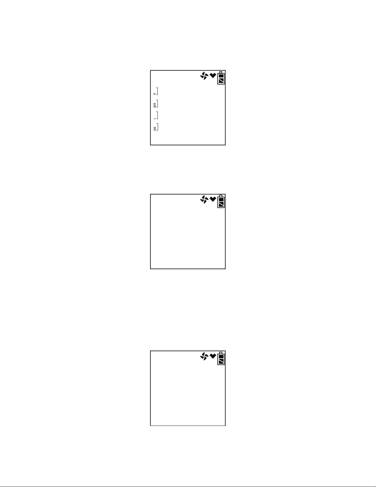
The lunch break feature enables the GX-2012 to remember peak readings
when it is turned off so it can continue them when it is turned on again. See
“Turning On the GX-2012, Normal Mode Only” on page 19. To reset the
peak readings during operation, press and hold the RESET SILENCE button
for a few seconds while in the peak screen.
CH4
O2
CO
H2S
PEAK
PEAK
0
20.9
0
0.0
%LEL
%
ppm
ppm
STEL Screen
The STEL Screen displays the short-term exposure limit (STEL) readings for
CO and H
minutes.
S only. The STEL reading is the average reading during the last 15
2
CO
H2S
STEL
0
0.0
ppm
ppm
TWA Screen
The TWA Screen displays the time-weighted average (TWA) readings for CO
and H
The TWA reading is the average reading during the last 8 hours. If 8 hours
have not elapsed since the last time the TWA reading was cleared, the
average is still calculated over 8 hours. The missing time is assigned a 0
value for readings.
S only.
2
CO
H2S
TWA
0
0.0
ppm
ppm
GX-2012 Operator’s Manual Display Mode • 45
Page 54

Alarm Points Screen
The Alarm Points Screen allows you to view each channel’s alarm settings
for full scale, warning, alarm, STEL (for CO and H
CO and H
S only). The bottom line of the screen will alternate between
2
S only), and TWA (for
2
ALARM--P, NO /DISP, and YES/ENT.
dISP
ALARM--P
Press the POWER ENTER button to proceed to view the full scale settings.
Use the AIRS or (SHIFT)T buttons to scroll through screens showing the
different settings.
vol%
CH4
O2
CO
H2S
F. S .
100
40.0
500
100.0
%LEL
%
ppm
ppm
CH4
O2
CO
H2S
WARNING
CH4
O2
CO
H2S
ALARM
46 • Display Mode GX-2012 Operator’s Manual
10
19.5
25
5.0
50
23.5
50
30.0
%LEL
%
ppm
ppm
%LEL
%
ppm
ppm
Page 55

CO
H2
STEL
200
S
15.0
ppm
ppm
CO
H2S
TWA
25
10.0
ppm
ppm
Pressing and releasing POWER ENTER while in a settings screen will cause
the instrument to simulate that condition. The buzzer, LEDs, and vibration
will activate. Press and release POWER ENTER again to stop the simulated
alarm.
Operation Time Screen
The operation time screen displays the time in minutes since the
GX-2012 was last turned on. The operation time may be continued from the
last time the GX-2012 was in operation by using the lunch break option. See
“Turning On the GX-2012, Normal Mode Only” on page 19.
OP. TIME
0:11
GX-2012 Operator’s Manual Display Mode • 47
Page 56

Date/Time Screen
The date/time screen displays the current date and time with the order being
year, month, day, time.
2011
8
31
22:39
DATE
Remaining Log Time Screen
The remaining log time screen displays the time remaining until the data
logger memory is full. The remaining log time depends on how often the GX2012 stores data to the data log, how many channels are active, and how often
the GX-2012 is turned on and off.
LOG
276
H
REMAIN
The table below illustrates how much data logging time is available for the
various interval times. It assumes that the unit is set up with all 5 sensors and
there are no alarm occurrences.
Table 6: Data Logging Capacity, 5 Sensor GX-2012
Interval
Time
10 seconds 10 hours
20 seconds 20 hours
30 seconds 30 hours
1 minute 60 hours
Data Logging Time
3 minutes 180 hours
5 minutes 300 hours
10 minutes 600 hours
48 • Display Mode GX-2012 Operator’s Manual
Page 57

Clear Data Logger Screens
CAUTION: Once you clear the data logger, you cannot retrieve any data
previously stored in the data logger.
NOTE: This item appears in Display Mode only if the DLOG DSP menu
item in Maintenance Mode is turned ON. The factory setting for
DLOG DSP is ON.
The clear data logger screens allow you to clear the data logger storage. You
can set the GX-2012 to overwrite the oldest data when the data log is full. See
“Updating the Datalog Overwrite Setting” on page 129. The bottom line of
the screen alternates between LG CLEAR, NO /DISP, and YES/ENT.
CLr
LOG
LG CLEAR
To clear the data log:
1. With the above screen displayed, press and release the POWER ENTER
button. The instrument will ask you to confirm that you want to clear the
data log and CLr LOG will be flashing. The bottom line of the screen
alternates between CONFIRM?, YES/ENT., AND NO /DISP.
CLr
LOG
CONFIRM?
2. To cancel the clear data log and return to the Clear Data Logger Screen in
Display Mode, press and release DISPLAY (ADJ).
To continue with the clear data log, press and release POWER ENTER.
GX-2012 Operator’s Manual Display Mode • 49
Page 58
3. The GX-2012 displays 4 dashes and as the GX-2012 clears the data, the
dashes disappear. When the last dash is gone, the GX-2012 has been
cleared and the remaining log time value is reset.
- - - -
LG CLEAR
Pump OFF Screen
WARNING: The GX-2012 is not a gas monitoring device while the pump
is off.
NOTE: This item appears in Display Mode only if the POFF DSP menu
item in Maintenance Mode is turned ON. The factory setting for
POFF DSP is OFF.
The GX-2012 pump can be turned on and off in this screen. The bottom line
of this screen alternates between PUMP OFF, NO /DISP, and YES/ENT.
This feature can be used to conserve battery life if there is a significant period
of time until the next gas monitoring task, but you do not want to wait for the
warmup sequence to complete if you turn the instrument off and on again.
On
PUMP OFF
In this screen, press POWER ENTER to turn the pump off. The fan in the
upper right corner of the screen will disappear. Once the pump is off, you
cannot exit this screen and return to normal operation or continue in Display
Mode until you turn the pump back on. To turn the pump back on and
continue in Display Mode or return to Normal Operation, press the POWER
ENTER button again.
50 • Display Mode GX-2012 Operator’s Manual
Page 59
User ID Screen
This screen displays only if ID DISP in the Maintenance Mode menu is set to
ON (see “Turning the ID Display Function On or Off” on page 135). Each
user ID can contain up to 16 characters but only the first 8 of those characters
are visible in the instrument. Be sure that all user IDs are distinguishable
from each other by viewing only the first 8 characters. For more information,
see the GX-2012 Data Logger Management Program manual. The bottom
line of the screen alternates between YES/ENT., the current user ID, and NO
/DISP. Uppercase letters, numbers, asterisks (*), dashes (-), and a blank space
are available characters. The GX-2012 can store 128 user IDs.
Use this screen to identify or change the user. The user ID provides a way to
identify the user during a data logging session. The user ID is saved to the
data logger for that session when you turn off the
GX-2012 or change users during operation. This allows you to change the
user ID during operation and have each user ID that was used during an
operating session saved for the corresponding data.
U Id
SEL
YES/ENT.
NOTE: As shipped from the factory, the user ID on this screen is shown as -
- -- -- -- -- -- until you enter this screen and select a user ID.
To change a user:
1. After entering Display Mode and proceeding to the User ID screen, press
and release the POWER ENTER button. The bottom line of this screen
alternates between YES/ENT., the current user ID, and NO /DISP.
U Id
SEL
USER--001
GX-2012 Operator’s Manual Display Mode • 51
Page 60

2. Use the AIRS and (SHIFT)T buttons to scroll through the 128 possible
user IDs.
3. Press the POWER ENTER button to select a user ID.
Station ID Screen
This screen displays only if ID DISP in the Maintenance Mode menu is set to
ON (see “Turning the ID Display Function On or Off” on page 135). Each
station ID can contain up to 16 characters but only the first 8 of those
characters are visible in the instrument. Be sure that all station IDs are
distinguishable from each other by viewing only the first 8 characters. For
more information, see the GX-2012 Data Logger Management Program
manual. The bottom line of the screen alternates between YES/ENT., the
current station ID, and NO /DISP. Uppercase letters, numbers, asterisks (*),
dashes (-), and a blank space are available characters. The GX-2012 can store
128 station IDs.
Use this screen to identify or change the station. The station ID provides a
way to identify the station during a data logging session. The station ID is
saved to the data logger for that session when you turn off the GX-2012 or
change stations during operation. This allows you to change the station ID
during operation and have each station ID that was used during an operating
session saved for the corresponding data.
S Id
SEL
YES/ENT.
NOTE: As shipped from the factory, the station ID on this screen is shown
as -- -- -- -- -- -- until you enter this screen and select a station ID.
52 • Display Mode GX-2012 Operator’s Manual
Page 61
To change a station:
1. After entering Display Mode and proceeding to the Station ID screen,
press and hold the POWER ENTER button. The bottom line of this
screen alternates between YES/ENT., the current station ID, and NO /
DISP.
S Id
SEL
001
2. Use the AIRS and (SHIFT)T buttons to scroll through the 128 possible
station IDs.
3. Press the POWER ENTER button to select a station ID.
Snap Logging Screen
The Snap Logging Screen allows you to view data from previous snap
loggings. For information on how to use the snap logging feature, see “Snap
Log Mode” on page 33.
1. To view snap logging data, use the AIRS and (SHIFT)T buttons to
scroll to the Snap Logging Screen. The bottom line of this screen
alternates between REC. DATA, NO /DISP, and YES/ENT.
d ISP
REC. DATA
2. Press and release the POWER ENTER button. If no snap logs have been
performed, the following screen will appear.
NO DATA
GX-2012 Operator’s Manual Display Mode • 53
Page 62
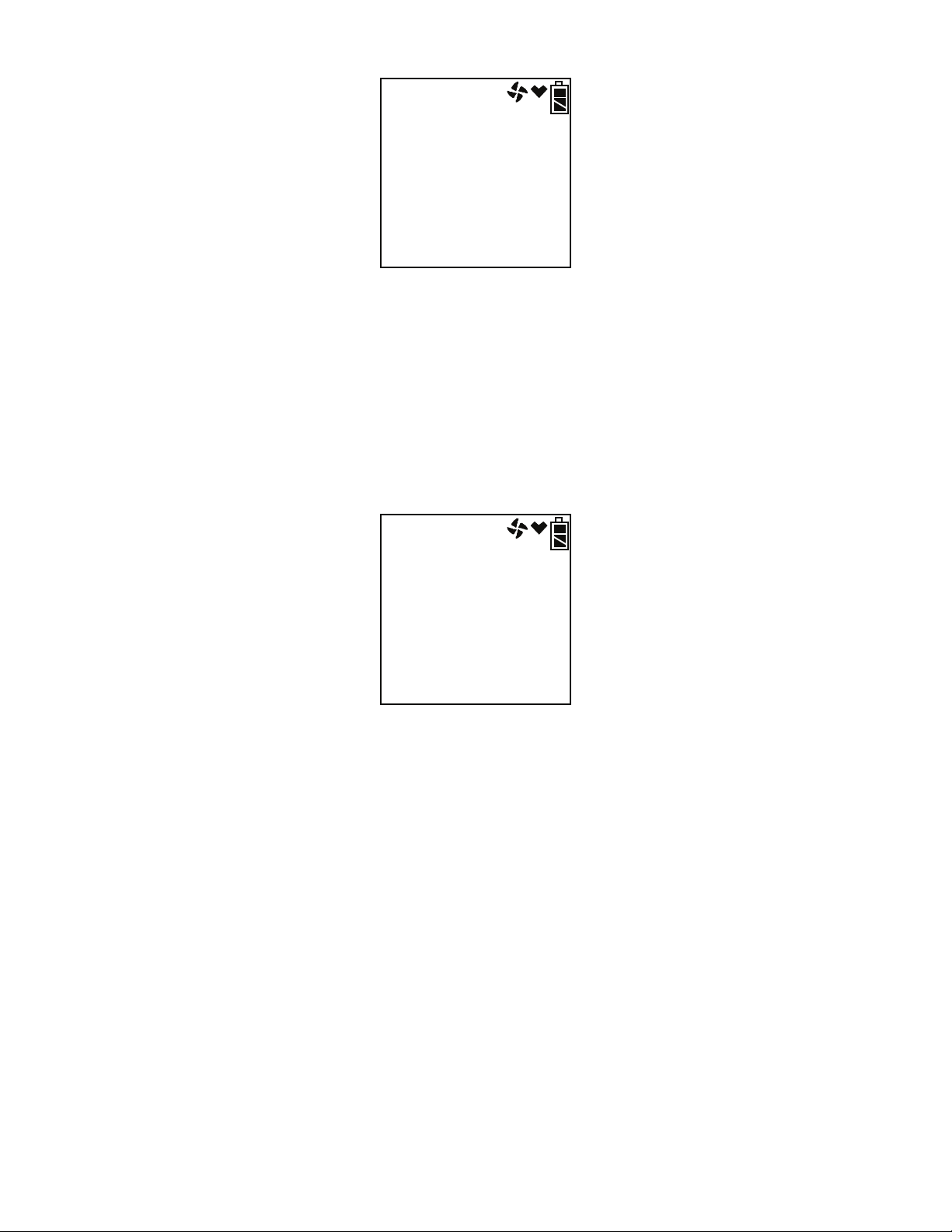
3. If snap logs have been performed, the following screen will appear.
2011
8
31
22:39
M023
This screen indicates the year, month, day, and time that the most recent
snap log was taken. The number along the bottom of the screen indicates
the snap log ID number. The first snap log that is taken is given an ID of
M001. The next snap log ID is M002. The ID number increases
sequentially with each set of snap log data. Use the AIRS and
(SHIFT)T buttons to scroll through different snap log IDs and view what
time they were taken.
4. To view the data in a snap log ID, press and release the POWER ENTER
button.
CH4
O2
CO
H2S
001
50
23.5
50
30.0
%LEL
%
ppm
ppm
The gas readings that were taken during the snap log are displayed and
the Station ID that was in use during the snap log is displayed along the
bottom of the screen. You can use the AIRS and (SHIFT)T buttons to
scroll through the different snap logs. The gas readings and station ID
will change but the snap log ID is not visible from this screen. To scroll
through the data by viewing the snap log ID number, press and release
POWER ENTER.
54 • Display Mode GX-2012 Operator’s Manual
Page 63
Peak Bar Select Screen
The Peak Bar Select Screen allows you to turn the peak bar on or off. If the
function is turned on, the peak bar appears along the left side of the screen
during Normal Operation and on the Peak Screen in Display Mode. It shows
the peak readings for each channel in bar graph format. The bottom line of
this screen alternates between the current setting, NO /DISP, and YES/ENT.
bAr
SEL
BAR OFF
To adjust the peak bar selection:
1. Use the DISPLAY (ADJ) button to scroll to the Peak Bar Select Screen.
The screen indicates the current setting.
bAr
SEL
BAR ON
2. Press and release the POWER ENTER button.
On
PEAK BAR
3. Use the AIRS and (SHIFT)T buttons to make your selection and press
and release the POWER ENTER button.
GX-2012 Operator’s Manual Display Mode • 55
Page 64

Data Logging
NOTE: The GX-2012 logs data in both Normal Mode and Bar Hole Mode.
The GX-2012 features the ability to log data to its internal memory and
download it to a computer via the infrared communications port located just
below the RESET SILENCE button. It logs gas readings during normal
operation, alarm data, and calibration data.
NOTE: The data logging function is separate from the snap logging
function. For a description of the snap logging function, see “Snap
Log Mode” on page 33.
To utilize the GX-2012’s downloading capability, you will need the GX-2012
downloading software and a computer with an infrared port or a USB port
that runs one of the following operating systems: Windows XP, Windows
Vista, or Windows 7. If your computer has an infrared port, then no
additional accessories are needed to download data from the GX-2012. If
your computer does not have an infrared port but does have a USB port, a
USB/IrDA adapter cable can be used to download data from the GX-2012
using a USB port. The downloading software is available from RKI
Instruments, Inc. The adapter cable is also available from RKI or may be
purchased at a computer or electronics supply store.
For a complete description of the downloading software and procedures for
downloading data to a computer, see the GX-2012 Data Logger Management
Program Operator’s Manual.
SDM-2012
The GX-2012 can be used with the SDM-2012 if desired. The
SDM-2012 can charge the instrument if the lithium ion battery pack is being
used. It can also bump test, calibrate, and retrieve saved data. The SDM-2012
can be operated as a single, stand-alone unit or can be used with up to 9 other
SDM-2012s and operated using a computer. For more information about the
operation of the SDM-2012, see the SDM-2012 operator’s manual.
56 • Data Logging GX-2012 Operator’s Manual
Page 65

Calibration Mode
Calibration Mode allows you to calibrate the GX-2012’s sensor response and
to bump test the GX-2012.
CAUTION: BEFORE EACH DAY’S USAGE, SENSITIVITY IN THE
% LEL RANGE MUST BE TESTED ON A KNOWN
CONCENTRATION OF THE COMBUSTIBLE TARGET GAS,
METHANE, EQUIVALENT TO 25 - 50% OF FULL SCALE
CONCENTRATION (The % LEL full scale is
100% LEL). ACCURACY MUST BE WITHIN -0 to + 20% OF
ACTUAL. ACCURACY MAY BE CORRECTED BY
FOLLOWING THE CALIBRATION INSTRUCTIONS FOR THE
COMBUSTIBLE CHANNEL BELOW.
If the combustible channel passes the above response test and does not
require calibration, the unit should still be calibrated periodically. The
optimum frequency of calibration depends heavily on how the GX-2012 is
used. For example, instruments used daily may need to be calibrated weekly
or monthly, while instruments that are used only a few times a year may need
to be calibrated before each use. Typical calibration frequencies range from
monthly to quarterly. Make sure to perform the combustible channel response
test as described above and make sure to develop a calibration schedule
tailored to your application that takes this test and required calibration
resulting from this test into account.
You can program the GX-2012 to notify you when it is due for calibration.
See “Updating the Calibration Reminder Setting” on page 130.
Calibration/Bump Test Supplies and Equipment
To calibrate or bump test the GX-2012, you will need:
• Known calibrating samples of the gases being detected. The combustible
and toxic gas samples should have concentrations in approximately the
middle of the range of detection. An oxygen-free source, such as 100%
nitrogen is recommended for setting the oxygen zero when using single
calibration.
• A demand-flow regulator to provide adequate sample gas flow
• Non-absorbent tubing
GX-2012 Operator’s Manual Calibration Mode • 57
Page 66

CAUTION: If you are using a calibration kit that includes a gas bag and a
fixed flow regulator or dispensing valve, do not apply gas
directly to the GX-2012 with the regulator or valve or damage to
the pump will result. See “Appendix A: Calibrating and Bump
Testing with a Sample Bag” on page 161 for instructions to
properly use a gas bag kit.
To calibrate or bump test the %LEL, Oxygen, CO, and H
S sensors at the
2
same time, automatically, with no need for a zero-oxygen source, you can use
the auto calibration feature with a 4-gas cylinder. If the H
S channel is not
2
active, then a 3-gas cylinder may be used for auto-calibration. This section
includes instructions for auto calibration and bump testing with a demandflow regulator, a 4-gas cylinder, and a %volume methane cylinder. This
section also includes instructions for calibrating one channel at a time using
single calibration.
NOTE: If the combustible gas channel(s) are calibrated to a gas other than
methane, use an appropriate multigas cylinder or use single
calibration to calibrate the combustible channel(s).
Preparing for Calibration or Bump Testing
Whether you will calibrate the GX-2012 using auto calibration, single
calibration, or perform a bump test, you will need to set the fresh air readings
first.
1. Find a fresh-air environment. This is an environment free of toxic or
combustible gases and of normal oxygen content (20.9%).
2. Turn on the unit as described in “Turning On the GX-2012, Normal Mode
Only” on page 19 or in “Turning On the GX-2012 in Normal Mode With
All Modes Active” on page 25. Use the sample hose and probe.
3. With the unit on, perform a fresh air adjustment by pressing and holding
the AIRS button. The display prompts you to hold the AIRS button.
4. Continue to hold the AIRS button until the display prompts you to
release it. The GX-2012 will set the fresh air reading for all channels as it
counts down from 8. If the combustible channel is set as %LEL only or
vol% only, there is no countdown period. The fresh air reading is set
immediately.
5. Install the demand flow regulator onto the calibration cylinder.
6. Connect the sample tubing to the demand flow regulator.
58 • Calibration Mode GX-2012 Operator’s Manual
Page 67

Calibrating the GX-2012
From Measuring Mode, enter Calibration Mode by pressing and holding the
(SHIFT)T button, then pressing the DISPLAY(ADJ) button and releasing
both. If the unit prompts you for the password, enter it by using the AIRS
and (SHIFT)T buttons to select each password number and then pressing
and releasing POWER ENTER to confirm it and move on to the next number.
To go back a number, press and release the RESET SILENCE button. The
factory set password is the same as the factory set password for Maintenance
Mode: 2102. You can change the password by entering the PASSWORD
menu item in Maintenance Mode. See “Turning the Password Function On or
Off” on page 141. If you enter an incorrect password, an error screen will
display.
PASSWORD
Err
To return to normal operation, press and release the RESET SILENCE
button. You may then try to reenter Calibration Mode.
MAINTENANCE will appear along the top of the screen once you have
entered Calibration Mode. The first item in the calibration menu, AIR CAL,
displays.
NOTE: The following screens illustrate a four-gas GX-2012 with both a
%LEL and a %volume combustible gas sensor as examples only.
Your GX-2012 may display slightly different screens.
MAINTENANCE
AIR CAL
The GX-2012’s calibration menu includes two methods of calibration:
auto calibration and single calibration.
• Auto Calibration: This method allows you to calibrate the combustible
gas (%LEL sensor only), OXY, H
GX-2012 Operator’s Manual Calibration Mode • 59
S, and CO sensors simultaneously. It is
2
Page 68

designed for use with the RKI 4-gas calibration cylinder and is the
quickest and easiest method to calibrate the
GX-2012. If installed, you may also calibrate the %volume sensor
separately from the standard four.
• Single Calibration: This method allows you to calibrate one sensor at a
time. Use this method if you are only calibrating one or two sensors, if
you are calibrating only the %volume combustible sensor, or if you are
not using the RKI 4-gas calibration cylinder.
Calibrating with the Auto Calibration Method
This section describes calibration using the auto calibration method.
To calibrate using the single calibration method, see “Calibrating with the
Single Calibration Method” on page 63. These instructions assume you are
using a 4-gas cylinder and a %volume methane cylinder.
NOTE: If the combustible gas channel(s) are calibrated to a gas other than
methane, use an appropriate multigas cylinder or use single
calibration to calibrate the combustible channel(s).
1. You may only calibrate either the standard 4 sensors or the % volume
combustible sensor at a time. Once you are finished, you are returned to
the initial AUTO CAL screen and must begin the auto calibration process
again.
2. Use the AIRS and (SHIFT)T buttons to display the AUTO CAL menu
item, press and release the POWER ENTER button to display the
calibration values screen. If you want to exit back to the main menu
without completing a calibration, press and release the DISPLAY (ADJ)
button.
60 • Calibration Mode GX-2012 Operator’s Manual
Page 69

3. Use the AIRS or (SHIFT)T button to alternate between the 4-gas and
the % volume combustible gas calibration values screens.
MAINTENANCE
CH4
O2
CO
H2S
AUTO CAL
MAINTENANCE
CH4
AUTO CAL
50
12.0
50
25.0
100
%LEL
%
ppm
ppm
vol%
4. The gas concentrations displayed in the calibration values screens must
match the gas concentrations listed on the calibration cylinders. If all
concentrations match, go to step 12. If one or more concentrations do not
match, continue with step 5.
5. To adjust the values on the screens, hold down the (SHIFT)T button,
then press the DISPLAY(ADJ) button and release both. The %LEL
sensor is shown here.
MAINTENANCE
CH4
AUTO CAL
- - -
%LEL
6. Use the AIRS and (SHIFT)T buttons to scroll through the sensors and
select the sensor whose calibration gas value you want to adjust.
7. Press and release the POWER ENTER button. The sensor’s calibration
gas value will flash.
8. If necessary, use the AIRS and (SHIFT)T buttons to set the correct
calibration gas value.
9. Press and release POWER ENTER button to save the change.
10. Repeat steps 6 through 9 to set the correct values for any additional
GX-2012 Operator’s Manual Calibration Mode • 61
Page 70

sensors.
11. After the last calibration gas value is set, use the AIRS button to scroll to
ESCAPE and press POWER ENTER to return to the calibration gas
values screens.
NOTE: The RKI Four Gas Cylinder typically contains 12% O
by volume.
2
Be sure to set the “OXY” reading to agree with the concentration
listed on the cylinder’s label, not zero.
12. Use the AIRS or (SHIFT)T button to select which sensor(s) you want to
calibrate, the standard 4 sensors or the %volume combustible gas sensor.
The following instructions illustrate calibrating the standard 4 sensors
first, then the %volume combustible gas sensor.
13. With the 4-gas calibration values screen displayed, press the
POWER ENTER button. AUTO CAL begins to flash and the current gas
readings are displayed. If you want to exit back to the main menu without
completing a calibration, press and release the DISPLAY (ADJ) button.
MAINTENANCE
CH4
O2
CO
H2S
AUTO CAL
0
20.9
0
0.0
%LEL
%
ppm
ppm
14. Connect the tubing from the demand flow regulator to the rigid tube on
the probe. Allow the gas to flow for one minute.
15. Press and release the POWER ENTER button to set the calibration to the
programmed values.
If all channels passed calibration, PASS displays along the bottom of the
screen, then the calibration menu displays.
62 • Calibration Mode GX-2012 Operator’s Manual
Page 71

If any of the sensors cannot calibrate to the proper value, FAIL displays
along the bottom of the screen and the GX-2012 lists the sensor(s) that
failed to calibrate. In the example below, the OXY and H
S channels
2
failed calibration. The other sensors calibrated normally.
MAINTENANCE
O2
FAIL
H2S
%
ppm
The buzzer and alarm lights activate. Press and release the RESET
SILENCE button after the buzzer and lights stop to reset the alarm and
return to the calibration menu. Attempt to calibrate again. If the failure
continues, investigate the cause. See “Troubleshooting” on page 143.
16. Disconnect the tubing from the probe.
17. Unscrew the demand flow regulator from the calibration cylinder.
18. If you have a 5 sensor unit and wish to calibrate the %volume
combustible gas sensor, go back to step 1 and repeat the process selecting
the %volume calibration gas value screen in step 12 and using a
%volume methane cylinder.
If you are finished calibrating, use the (SHIFT)T button to navigate to
the NORMAL menu item, then press and release the POWER ENTER
button to return to Measuring Mode.
Calibrating with the Single Calibration Method
This section describes calibration using the Single Calibration method.
To calibrate using the Auto Calibration method, see “Calibrating with the
Auto Calibration Method” on page 60.
The procedure below describes a span adjustment of one channel using a
calibration kit that includes a 4-gas calibration cylinder, a 0.5 LPM (liters per
minute) regulator, and non-absorbent sample tubing. The standard 4-gas
cylinder consists of 50% LEL methane, 12% oxygen, 50 ppm CO, 25 ppm
S, and a balance of nitrogen. In the example below, the CH4 channel’s
H
2
span is adjusted. See “Parts List” on page 158 for available calibration kits
and calibration kit spare parts.
Calibration cylinders that contain only one target gas may also be used for
single calibration. For channels other than oxygen, RKI Instruments, Inc.
recommends that you use a cylinder that contains a concentration of 10-50%
GX-2012 Operator’s Manual Calibration Mode • 63
Page 72

of the full scale value of the target gas. For example, if you are calibrating the
combustible gas channel, your calibration cylinder should have a
combustible gas concentration between 10% LEL and 50% LEL. For the
oxygen channel, RKI Instruments, Inc. recommends using 100% nitrogen to
perform the adjustment but any concentration between 0% oxygen (100%
nitrogen) and 17% oxygen can be used to make the adjustment.
NOTE: If your combustible gas channel is calibrated to a gas other than
methane, use an appropriate gas cylinder to perform the calibration.
CAUTION: The single calibration method does not have a “FAIL”
notification. If a sensor cannot be set to agree with the
calibration source, see “Troubleshooting” on page 143.
1. While in the calibration menu, use the AIRS or (SHIFT)T button to
navigate to the ONE CAL menu option.
MAINTENANCE
ONE CAL
2. Press and release the POWER ENTER button to display the single
calibration menu. The %LEL sensor will be displayed first.
MAINTENANCE
CH4
ONE CAL
- - -
%LEL
64 • Calibration Mode GX-2012 Operator’s Manual
Page 73

3. Use the AIRS or (SHIFT)T button to display the sensor you want to
calibrate (in this example the combustible gas % LEL sensor). If you
have a 5 sensor unit, the %vol sensor will be one of the choices. It is
shown below.
MAINTENANCE
CH4
ONE CAL
- - -
vol%
4. Press and release the POWER ENTER button. The single calibration
screen displays for the sensor you selected. The gas reading flashes.
MAINTENANCE
CH4
ONE CAL
0
%LEL
5. Connect the tubing from the demand flow regulator to the rigid tube on
the probe. Allow the calibration gas to flow for one minute.
6. If necessary, use the AIRS and (SHIFT)T buttons to adjust the reading
to match the concentration listed on the calibration cylinder.
If the reading already matches the concentration listed on the calibration
cylinder, press and release the AIRS button then press and release the
(SHIFT)T button so that the instrument sees a change and resets the
calibration date.
7. Press and release the POWER ENTER button to save the span value. The
LCD will indicate that the calibration has ended, then the single
calibration menu displays.
MAINTENANCE
CH4
ONE CAL
- - -
%LEL
GX-2012 Operator’s Manual Calibration Mode • 65
Page 74

8. Disconnect the tubing from the probe.
9. Repeat steps 3 through 8 for any other sensors you want to calibrate.
Make sure you use an appropriate calibration cylinder for each sensor.
CAUTION: When calibrating the oxygen channel, verify the concentration
of oxygen listed on the cylinder’s label. For oxygen-free samples
(100% nitrogen for example), set the oxygen zero setting to
0.0%.
10. After the last channel is calibrated, disconnect the calibration tubing from
the probe, then unscrew the demand flow regulator from the calibration
cylinder.
11. Use the AIRS and (SHIFT)T buttons to scroll to ESCAPE in the ONE
CAL menu.
12. Press and release the POWER ENTER button to exit ONE CAL.
13. With the ONE CAL menu option displayed, press the (SHIFT)T button
until the NORMAL menu option is displayed.
14. Press and release the POWER ENTER button to return to Measuring
Mode.
Bump Testing the GX-2012
NOTE: The BUMP DSP menu item in Maintenance Mode is factory set to
OFF. The BUMP menu item will not appear unless BUMP DSP is
set to ON. See “Turning the Bump Test Function On or Off” on
page 125 for instructions.
NOTE: The GX-2012 uses parameters defined in the BUMP--SET menu
item of Maintenance Mode while performing a bump test. To view
or update these parameters, see “Updating the Bump Test
Parameters” on page 127.
NOTE: If the combustible gas channel(s) are calibrated to a gas other than
methane, use an appropriate multigas cylinder.
66 • Calibration Mode GX-2012 Operator’s Manual
Page 75
From Measuring Mode, enter Calibration Mode by pressing and holding the
(SHIFT)T button, then pressing the DISPLAY(ADJ) button and releasing
both. If the unit prompts you for the password, enter it by using the AIRS
and (SHIFT)T buttons to select each password number and then pressing
and releasing POWER ENTER to confirm it and move on to the next number.
To go back a number, press and release the RESET SILENCE button. The
factory set password is the same as the factory set password for Maintenance
Mode: 2102. You can change the password by entering the PASSWORD
menu item in Maintenance Mode. See “Turning the Password Function On or
Off” on page 141. If you enter an incorrect password, an error screen will
display.
PASSWORD
Err
To return to normal operation, press and release the RESET SILENCE
button. You may then try to reenter Calibration Mode.
MAINTENANCE will appear along the top of the screen once you have
entered Calibration Mode. The first item in the calibration menu, AIR CAL,
displays.
1. Install the demand flow regulator onto the calibration cylinder.
2. Connect the sample tubing to the demand flow regulator.
3. Install the hose and probe to the GX-2012.
4. Use the AIRS or (SHIFT)T buttons to display the BUMP menu item.
MAINTENANCE
BUMP
GX-2012 Operator’s Manual Calibration Mode • 67
Page 76

5. Press and release the POWER ENTER button to display the bump test
gas values.
MAINTENANCE
CH4
O2
CO
H2S
BUMP 30
50
12.0
50
25.0
%LEL
%
ppm
ppm
6. Use the AIRS or (SHIFT)T buttons to see the %volume combustible
gas bump test value.
MAINTENANCE
CH4
BUMP 30
100
vol%
7. A bump test may be performed on the standard 4 sensors or on the
%volume combustible sensor. Use the AIRS or (SHIFT)T buttons to
display the screen for the sensor(s) you wish to bump test.
8. Before proceeding, confirm that the bump test gas value(s) are the same
as the concentration(s) in the calibration cylinder. If they are not, adjust
the bump test gas value(s) by entering the AUTO CAL menu item,
changing the values there, and reentering the BUMP menu.
9. Connect the tubing from the demand flow regulator to the rigid tube on
the probe then quickly press and release the POWER ENTER button. The
unit will begin counting down from 30.
68 • Calibration Mode GX-2012 Operator’s Manual
Page 77
10. When AUTO CAL in the BUMP--SET menu item in Maintenance Mode
is set to OFF:
• The instrument will indicate which channels passed or failed the
bump test with a P (pass) or an F (fail) to the right of the gas.
MAINTENANCE
CH4
O2
CO
H2S
BUMP
F
P
F
P
%LEL
%
ppm
ppm
• To view the bump test gas readings press the AIRS or (SHIFT)T
button. You can scroll between the bump test results and the bump
test gas readings with the AIRS or (SHIFT)T button.
MAINTENANCE
CH4
O2
CO
H2S
BUMP
5
12.0
10
25.0
%LEL
%
ppm
ppm
• To return to the BUMP screen in Calibration Mode, press POWER
ENTER.
MAINTENANCE
BUMP
If one or more sensors fail the bump test, see “Troubleshooting” on
page 143 to investigate the cause of the failure and replace the failed
sensor or sensors if necessary.
• Disconnect the tubing from the probe.
GX-2012 Operator’s Manual Calibration Mode • 69
Page 78
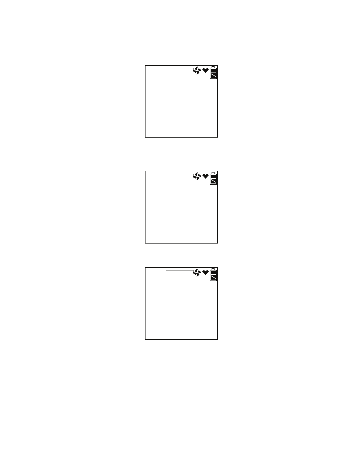
11. When AUTO CAL in the BUMP--SET menu item in Maintenance Mode
is set to ON:
If all channels pass the bump test,
• The following screen appears:
MAINTENANCE
CH4
O2
CO
H2S
BUMP
P
P
P
P
%LEL
%
ppm
ppm
• To view the bump test gas readings press the AIRS or (SHIFT)T
button. You can scroll between the bump test results and the bump
test gas readings with the AIRS or (SHIFT)T buttons.
MAINTENANCE
CH4
O2
CO
H2S
BUMP
45
12.0
47
23.0
%LEL
%
ppm
ppm
• To return to the BUMP screen in Calibration Mode, press POWER
ENTER.
MAINTENANCE
BUMP
• Disconnect the tubing from the probe.
If any channel fails the bump test,
• The instrument will beep and a calibration is immediately and
automatically started. Continue to apply the calibration gas. CAL on
the bottom left of the screen will alternate with APPLY.
The calibration time will begin to countdown in seconds in the lower
right of the screen. The calibration time counted down during a
70 • Calibration Mode GX-2012 Operator’s Manual
Page 79
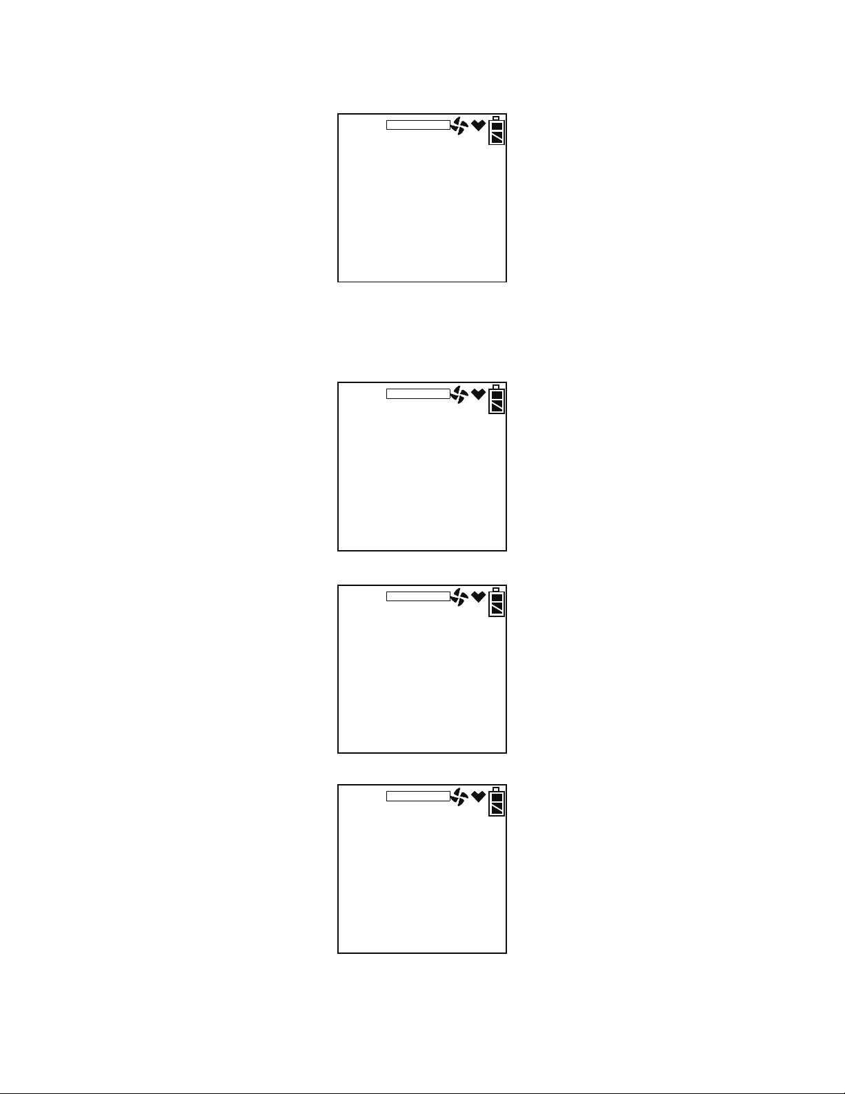
calibration initiated because of a failed bump test is the difference
between the bump test gas time and the calibration time defined in the
BUMP--SET menu item in Maintenance Mode.
MAINTENANCE
CH4
O2
CO
H2S
CAL 60
1
20.9
37
10.0
%LEL
%
ppm
ppm
• At the end of the calibration, the instrument displays the results from
both the bump test and the calibration. Use the AIRS or (SHIFT)T
button to scroll between the calibration/bump test results, the bump
test gas readings, and the calibration gas readings.
MAINTENANCE
CH4
O2
CO
H2S
BUMP/CAL
FP
PP
FF
PP
%LEL
%
ppm
ppm
MAINTENANCE
CH4
O2
CO
H2S
BUMP/
MAINTENANCE
CH4
O2
CO
H2S
/CAL
1
12.0
5
23.0
49
12.0
5
25.0
%LEL
%
ppm
ppm
%LEL
%
ppm
ppm
GX-2012 Operator’s Manual Calibration Mode • 71
Page 80

• To return to the BUMP screen in Calibration Mode, press POWER
ENTER at any time. If any channel failed the calibration, the buzzer
will sound a double pulsing tone until you press and release the
POWER ENTER button.
MAINTENANCE
BUMP
• Disconnect the tubing from the probe.
12. Unscrew the demand flow regulator from the calibration cylinder.
13. With the BUMP menu option displayed, press the (SHIFT)T button until
the NORMAL menu option is displayed.
14. Press and release the POWER ENTER button to return to Measuring
Mode.
72 • Calibration Mode GX-2012 Operator’s Manual
Page 81

Chapter 4: Using the GX-2012 in Bar Hole Mode
Overview
This chapter explains how to operate the GX-2012 in Bar Hole Mode. Bar
Hole Mode is used to perform consistent checks of bar holes when tracking
down underground gas leaks. When the GX-2012 is in Bar Hole Mode, only
the combustible and oxygen channels are displayed.
If a GX-2012 is intended for bar hole testing, it is shipped with Bar Hole
Mode enabled so that the operator must choose which operational mode to
use when the unit is turned on.
NOTE: Units intended for bar hole testing are typically calibrated to
methane. In addition, the unit must have a %volume combustible
sensor installed.
Start Up, Bar Hole Mode
This section explains how to start up the GX-2012 in Bar Hole Mode and get
it ready for operation.
Turning On the GX-2012, Bar Hole Mode
WARNING: If a CO or H2S sensor is installed, these sensors will not be
active while the GX-2012 is in Bar Hole Mode.
WARNING: Gas alarms are not active when the GX-2012 is in Bar Hole
Mode.
The following description of the GX-2012 start up sequence assumes that the
following menu items in Maintenance Mode are turned on: LNCH BRK, ID
DISP, CL RMNDR, and BP RMNDR. If either of these items is turned off,
then the corresponding screen will not appear.
NOTE: In order for BAR HOLE MODE to appear as a selection in the
Mode Select Screen in Step 3 below, the L./B. MODE menu item in
Maintenance Mode must be set to bH or LC bH.
1. Connect the sample hose to the GX-2012’s quick connect inlet fitting.
2. Screw the bar hole probe onto the sample hose’s threaded fitting.
GX-2012 Operator’s Manual Overview • 73
Page 82
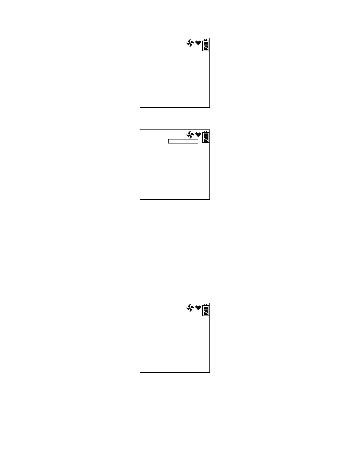
3. Press and briefly hold down the POWER ENTER button. The Normal
Mode Select Screen displays.
vol%
CH4
O2
CO
H2S
NORMAL ?
0
20.9
0
0.0
%LEL
%
ppm
ppm
4. Use the AIRS or (SHIFT)T buttons to scroll to the Bar Hole Mode
Select Screen.
BAR HOLE MODE
CH4
O2
0
20.9
30
B.H. MODE?
vol%
%LEL
ppm
vol%
%
sec
5. With the Bar Hole Mode Select Screen displayed, press and release the
POWER ENTER button to begin the Bar Hole Mode startup sequence.
NOTE: If no button is pressed for 20 seconds, the unit will proceed into
whichever mode is displayed.
6. If CL RMNDR is turned on (factory setting), the screen that appears next
depends on how CL EXPRD is set in the Maintenance Mode Menu
(page 130).
• If the unit is due for calibration and CL EXPRD is set to CONFIRM
(factory setting), then the following screen displays.
CAL
C--LIMIT
The alarm LED’s and buzzer will pulse several times. After this,
press and release the RESET SILENCE button to continue.
74 • Start Up, Bar Hole Mode GX-2012 Operator’s Manual
Page 83

• If the unit is due for calibration and CL EXPRD is set to NOT USE,
then the following screen displays.
FAIL
C--LIMIT
The GX-2012 cannot be used until a calibration has been performed
either by selecting AUTO CAL or ONE CAL in the Maintenance
Mode menu. See “Calibrating Using Auto Calibration” on page 105
or “Calibrating Using Single Calibration” on page 108 for calibration
instructions.
• If calibration is not due or CL EXPRD is set to NO EFFECT, then
the following screen appears for a few seconds indicating when the
next calibration is due.
2011
9
30
69d
NEXT CAL
7. If BP RMNDR is turned on (factory setting is OFF), the screen that
appears next depends on how BP EXPRD is set in the Maintenance
Mode Menu (page 131).
• If the unit is due for a bump test and BP EXPRD is set to CONFIRM
(factory setting), then the following screen displays.
tESt
B--LIMIT
The alarm LED’s and buzzer will pulse several times. After this,
press the RESET SILENCE button until you hear a beep to continue.
GX-2012 Operator’s Manual Start Up, Bar Hole Mode • 75
Page 84

• If the unit is due for a bump test and BP EXPRD is set to NOT USE,
then the following screen displays.
FAIL
B--LIMIT
The GX-2012 cannot be used until a bump test has been performed
by selecting BUMP in the Maintenance Mode menu. See
“Performing a Bump Test” on page 111 for bump testing instructions.
• If a bump test is not due or BP EXPRD is set to NO EFFECT, then
the following screen appears for a few seconds indicating when the
next bump test is due.
2011
9
30
10d
NEXTBUMP
NOTE: If both CL RMNDR and BP RMNDR are turned off, a WARM UP
screen will display before the warm up sequence continues.
76 • Start Up, Bar Hole Mode GX-2012 Operator’s Manual
Page 85

8. If ID DISP is turned on (see page 135), the User ID Screen displays for a
few seconds and then the Station ID Screen displays for a few seconds.
U Id
- - - - - - - -
S Id
- - - - - - - -
9. The Date/Time Screen appears for a few seconds.
2011
8
31
22:39
DATE
This screen displays the current year, month, date, and time.
10. The Battery Level and Alarm Pattern Screen appears next.
bAtt
3.7
AL-H V
GX-2012 Operator’s Manual Start Up, Bar Hole Mode • 77
Page 86

AL -- H indicates latching (hold) alarms and AL -- A indicates selfresetting (automatic) alarms. The number shown indicates the voltage of
the batteries. A fully charged lithium ion battery pack will display 3.7 V.
If the unit is powered by alkaline (dry cell) batteries, a “D” will appear in
front of the “V” in the lower right corner.
bAtt
3.7
AL-H D: V
11. The display then indicates the following items for about a second each:
• Full scale values for all channels
• Warning setpoint (low gas alarm) for all channels
• Alarm setpoint (high gas alarm) for all channels
• STEL alarm setpoint for the CO and H
• TWA alarm setpoint for the CO and H
S channels
2
S channels
2
12. If the GX-2012 experiences a sensor failure during start up, a screen
indicating which sensor failed displays. In the example below, the
combustible gas %volume sensor has failed.
CH4
FAIL
vol%
SENSOR
If one of the combustible sensors, LEL or % volume, fails, it is not
possible to enter Bar Hole Mode. Press and release the RESET SILENCE
button to acknowledge the failure and return to the Mode Select Screen.
Replace the failed sensor as soon as possible.
If the oxygen sensor fails, press and release the RESET SILENCE button
to acknowledge the failure and continue to Bar Hole Mode. The gas
reading for the oxygen sensor will be replaced by “XXX”. Replace the
failed sensor as soon as possible.
78 • Start Up, Bar Hole Mode GX-2012 Operator’s Manual
Page 87

If the CO or H2S sensor is installed and fails, press and release the
RESET SILENCE button to acknowledge the failure and continue to Bar
Hole Mode.
13. The GX-2012 is now operating in Bar Hole Mode. The pump is off and
the following screen appears.
BAR HOLE MODE
CH4
O2
001
0
20.9
%LEL
%
The methane and oxygen channels are displayed along with the battery
charge level.
Performing a Fresh Air Adjustment, Bar Hole Mode
Before using the GX-2012, it is recommended to set the fresh air readings for
the target gases by performing a fresh air adjustment. This will set the
combustible gas channel to zero and the OXY channel to 20.9%.
1. Find a fresh-air environment. This is an environment free of toxic or
combustible gases and of normal oxygen content (20.9%).
2. Turn on the unit as described above in “Turning On the GX-2012, Bar
Hole Mode”.
3. Press and hold the AIRS button. The pump will start and the display will
prompt you to hold the AIRS button.
4. Continue to hold the AIRS button until the display prompts you to
release the AIRS button. The GX-2012 will set the fresh air reading for
the CH
and oxygen channels as it counts down from 8. Once the
4
countdown has finished, start up is complete and the unit is ready for bar
hole testing.
GX-2012 Operator’s Manual Start Up, Bar Hole Mode • 79
Page 88

Bar Hole Testing
In Bar Hole Mode, the you can initiate sampling for a fixed time period to
monitor for methane and oxygen in a bar hole. The factory set time is 30
seconds. To change the bar hole sampling time, see “Updating the Bar Hole
Sampling Time” on page 138. At the end of the sample period, the pump will
shut off and the peak methane and minimum oxygen levels monitored during
the sample period will be displayed. Bar Hole Mode also allows you to
initiate an air purge cycle to purge gas from the GX-2012 after a sample is
taken.
In a low-light environment, press and release the (SHIFT)T button to turn on
the display backlight. Although the backlight will turn on when any button is
pressed, other buttons may initiate an undesired operation sequence. See
“Updating the LCD Back Light Time Setting” on page 135 to program
backlight duration. If BEEP. SET is turned on in the Maintenance Mode
menu, the GX-2012 beeps once every 5 minutes to confirm that it’s
operating.
While in Bar Hole Mode, you may select or change the current station ID by
pressing the (SHIFT)T button and DISPLAY (ADJ) button and releasing
when you hear a beep.
Performing a Bar Hole Test
1. Start up the GX-2012 as described in “Start Up, Bar Hole Mode” on
page 73.
2. If you wish to change the station ID, press the (SHIFT)T and DISPLAY
(ADJ) buttons and release when you hear a beep. The current station ID
will be displayed and it will be flashing. If you wish to exit the Station ID
Select Screen without making any changes, press and release the RESET
SILENCE button.
S Id
SEL
001
80 • Bar Hole Testing GX-2012 Operator’s Manual
Page 89

Use the AIRS and (SHIFT)T buttons to scroll to the desired station ID
and press and release POWER ENTER. The unit will return to the Bar
Hole Measuring Screen.
BAR HOLE MODE
CH4
O2
001
0
0.0
%LEL
%
3. Take the GX-2012 to the bar hole that will be tested.
4. Insert the probe into the bar hole and press and release the POWER
ENTER button. The pump will turn on and the sample period will begin
with the sample period counting down in seconds in the lower right
corner of the display. The CH
channel will be displayed in %VOL. The
4
methane channel’s reading will also be displayed in graph format on the
left side of the screen. If you wish to cancel the measurement, press and
release the RESET SILENCE button.
BAR HOLE MODE
CH4
O2
MEASURE
25
20.9
30
vol%
%
sec
5. After 15 seconds of sampling, if the combustible gas reading is less than
5 %VOL, the combustible gas channel will automatically begin
displaying in %LEL.
GX-2012 Operator’s Manual Bar Hole Testing • 81
Page 90
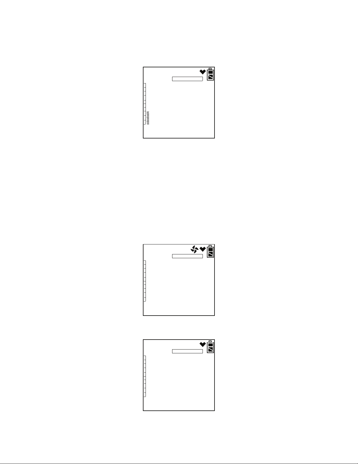
6. At the end of the sample period, the pump will shut off and the buzzer
will sound, then the peak methane reading and the minimum oxygen
reading for the sample period will be displayed. The peak methane
reading will also be visually displayed on the graph along the left side of
the screen.
BAR HOLE MODE
CH4
O2
PEAK
PEAK
25
19.0
%LEL
%
7. If a high concentration of methane is encountered, a fresh air purge can
be performed to purge the hose, probe and GX-2012 of gas before the
next bar hole test. To perform a purge, do the following:
• Remove the probe from the barhole so the instrument will draw fresh
air.
• Press and release the DISPLAY (ADJ) button. The display will now
indicate PURGE along the bottom of the screen and the purge time
will begin counting down from 30 seconds in the lower right corner
of the display. If you wish to cancel the purge, press and release the
RESET SILENCE button.
BAR HOLE MODE
CH4
O2
PURGE
0
20.9
30
vol%
%
sec
• When the purge is complete, the screen will return to the initial Bar
Hole Mode screen.
BAR HOLE MODE
CH4
O2
0
20.9
%LEL
%
001
82 • Bar Hole Testing GX-2012 Operator’s Manual
Page 91

8. If other bar holes will be tested, proceed to the next bar hole and repeat
steps 4 - 7.
9. To cancel a bar hole measurement or fresh air purge that is in progress,
press and release the RESET SILENCE button.
10. To exit Bar Hole Mode and return to the Mode Select Screen at any time,
press and hold the (SHIFT)T button for 5 seconds.
Turning Off the GX-2012, Bar Hole Mode
1. Press and hold the POWER ENTER button.
2. The unit will initiate a bar hole measurement. Keep holding the POWER
ENTER button. The buzzer will pulse for about three seconds and TURN
OFF will appear at the bottom of the screen.
3. Release the button when TURN OFF disappears.
GX-2012 Operator’s Manual Bar Hole Testing • 83
Page 92

Chapter 5: Using the GX-2012 in Leak Check Mode
Overview
This chapter explains how to operate the GX-2012 in Leak Check Mode.
Leak Check Mode is used to pinpoint small leaks of combustible gas from
valves, flanges, connections, and other potential leak points. When the GX2012 is in Leak Check Mode, only the combustible channel is displayed.
If a GX-2012 is intended for leak check testing, it is shipped with Leak
Check Mode enabled so that the operator must choose which operational
mode to use when the unit is turned on (see “Turning On the GX-2012 in
Normal Mode With All Modes Active” on page 25).
NOTE: In order to use the GX-2012 for Leak Check Mode operation, the
LEL/ppm sensor (NC-6264ALB) must be installed. The LEL sensor
cannot be used.
Start Up, Leak Check Mode
This section explains how to start up the GX-2012 in Leak Check Mode and
get it ready for operation.
NOTE: The battery drain is higher in Leak Check Mode than in Normal
Mode or Bar Hole Mode. Extended operation in this mode will
result in shorter battery life than specified in “Specifications” on
page 3.
Turning On the GX-2012, Leak Check Mode
WARNING: If an oxygen or H2S sensor is installed, these sensors will not
be active while the GX-2012 is in Leak Check Mode.
The following description of the GX-2012 start up sequence assumes that the
following menu items in Maintenance Mode are turned on: LNCH BRK, ID
DISP, CL RMNDR, and BP RMNDR. If either of these items is turned off,
then the corresponding screen will not appear.
84 • Ove rview GX-2012 Operator’s Manual
Page 93
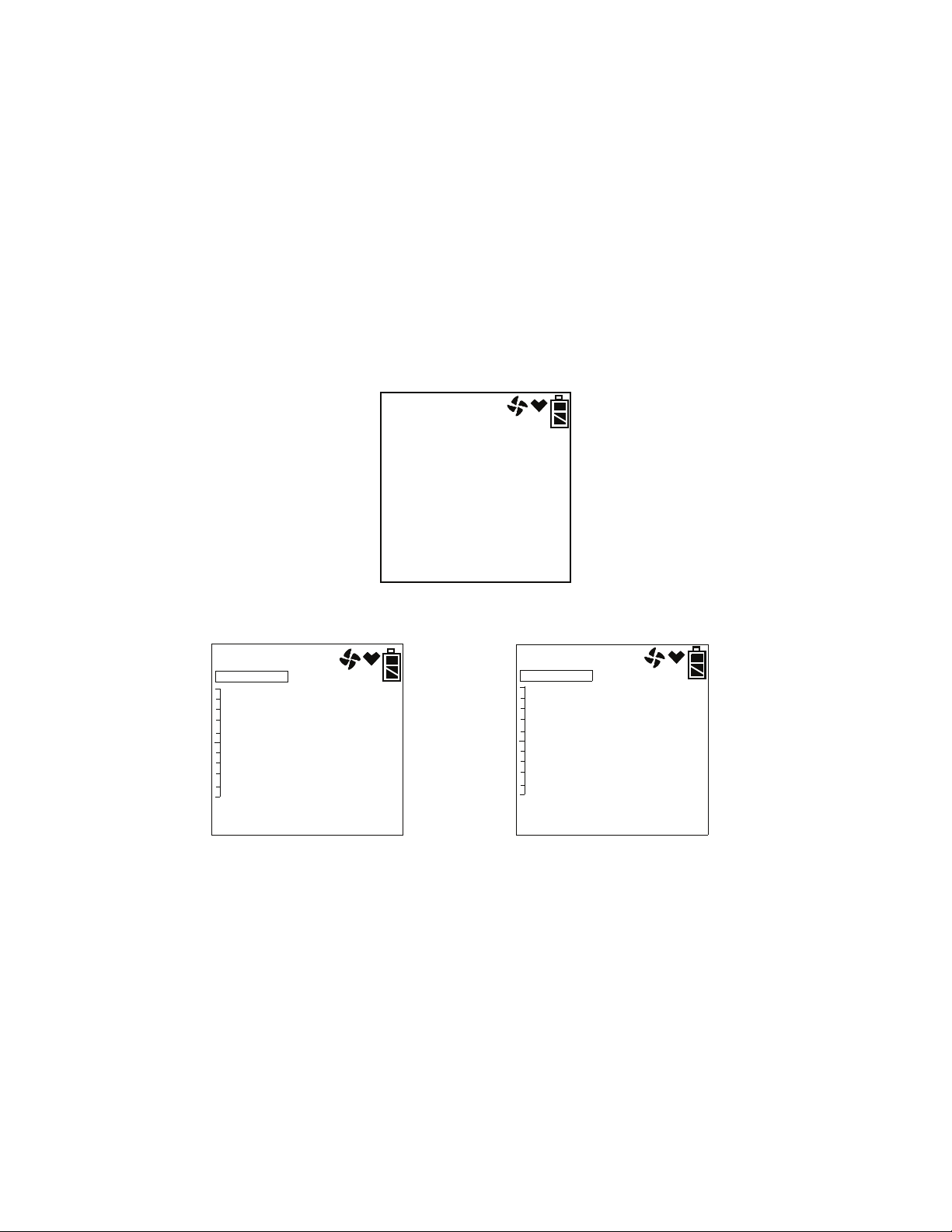
NOTE: In order for LEAK CHECK MODE to appear as a selection in the
Mode Select Screen in Step 3 below, the L./B. MODE item in
Maintenance Mode must be set to LC or LC bH. The factory setting
is OFF.
1. Connect the tapered rubber nozzle to the inlet fitting.
2. If a sample hose is used, connect the sample hose to the GX-2012’s quick
connect inlet fitting.
NOTE: If a probe is used when using the GX-2012 in Leak Check Mode,
use the standard probe, not the bar hole probe.
3. Press and briefly hold down the POWER ENTER button. The Normal
Mode Select Screen displays.
vol%
CH4
O2
CO
H2S
NORMAL ?
0
20.9
0
0.0
%LEL
%
ppm
ppm
4. Use the AIRS or (SHIFT)T button to scroll to the Leak Check Mode
Select Screen.
LEAK CK MODE
CH4
L.C. MODE?
0
5000
ppm
ppm
LEAK CK MODE
CH4
CO
L.C. MODE?
0
0
5000
ppm
ppm
ppm
CO DISP OFF CO DISP On
NOTE: If the CO DISP parameter in Maintenance Mode is set to On, the
CO channel will appear in Leak Check Mode. If the CO DISP
parameter is set to OFF (factory setting), the CO channel will not
appear in Leak Check Mode. All screens in this section do not show
the CO channel. If CO DISP is turned on for your instrument, your
screens may appear different.
5. With the Leak Check Mode Select Screen displayed, press and release the
POWER ENTER button to begin the Leak Check Mode startup sequence.
GX-2012 Operator’s Manual Start Up, Leak Check Mode • 85
Page 94
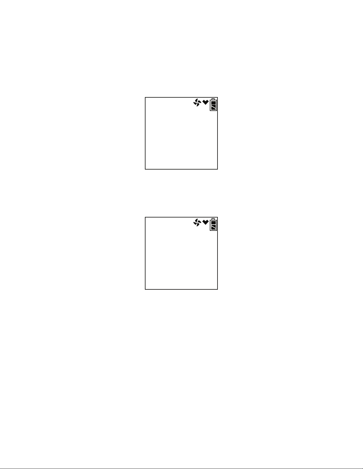
NOTE: If no button is pressed for 20 seconds, the unit will proceed into
whichever mode is displayed.
6. If CL RMNDR is turned on (factory setting), the screen that appears next
depends on how CL EXPRD is set in the Maintenance Mode Menu
(page 131).
• If the unit is due for calibration and CL EXPRD is set to CONFIRM
(factory setting), then the following screen displays.
CAL
C--LIMIT
The alarm LED’s and buzzer will pulse several times. After this,
press and release the RESET SILENCE button to continue.
• If the unit is due for calibration and CL EXPRD is set to NOT USE,
then the following screen displays.
FAIL
C--LIMIT
The GX-2012 cannot be used until a calibration has been performed
either by selecting AUTO CAL, or ONE CAL in the Maintenance
Mode menu. See “Calibrating Using Auto Calibration” on page 105
or “Calibrating Using Single Calibration” on page 108 for calibration
instructions.
86 • Start Up, Leak Check Mode GX-2012 Operator’s Manual
Page 95
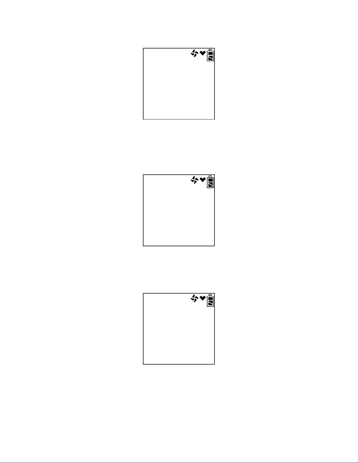
• If calibration is not due or CL EXPRD is set to NO EFFECT, then
the following screen appears for a few seconds indicating when the
next calibration is due.
2011
9
30
69d
NEXT CAL
7. If BP RMNDR is turned on (factory setting is OFF), the screen that
appears next depends on how BP EXPRD is set in the Maintenance Mode
Menu (page 133).
• If the unit is due for a bump test and BP EXPRD is set to CONFIRM
(factory setting), then the following screen displays.
tESt
B--LIMIT
The alarm LED’s and buzzer will pulse several times. After this,
press the RESET SILENCE button until you hear a beep to continue.
• If the unit is due for a bump test and BP EXPRD is set to NOT USE,
then the following screen displays.
FAIL
B--LIMIT
The GX-2012 cannot be used until a bump test has been performed
by selecting BUMP in the Maintenance Mode menu. See
“Performing a Bump Test” on page 111 for bump testing instructions.
GX-2012 Operator’s Manual Start Up, Leak Check Mode • 87
Page 96

• If a bump test is not due or BP EXPRD is set to NO EFFECT, then
the following screen appears for a few seconds indicating when the
next bump test is due.
2011
9
30
10d
NEXTBUMP
NOTE: If both CL RMNDR and BP RMNDR are turned off, a WARM UP
screen will display before the warm up sequence continues.
8. If ID DISP is turned on, the User ID Screen displays for a few seconds
and then the Station ID Screen displays for a few seconds.
U Id
- - - - - - - -
S Id
- - - - - - - -
9. The Date/Time Screen appears for a few seconds.
2011
8
31
22:39
DATE
This screen displays the current year, month, date, and time.
88 • Start Up, Leak Check Mode GX-2012 Operator’s Manual
Page 97

10.The Battery Level and Alarm Pattern Screen appears next.
bAtt
3.7
AL-H V
AL -- H indicates latching (hold) alarms and AL -- A indicates selfresetting (automatic) alarms. The number shown indicates the voltage of
the batteries. If the unit is powered by alkaline (dry cell) batteries, a “D”
will appear before the “V” in the lower right corner.
bAtt
3.7
AL-H D: V
11.The display then indicates the full scale values for all channels.
12.If the GX-2012 experiences a sensor failure during start up, a screen
indicating which sensor failed displays. In the example below, the
catalytic LEL sensor has failed.
CH4
SENSOR
If the catalytic LEL sensor fails, it is not possible to enter Leak Check
Mode. Press and release the RESET SILENCE button twice to
acknowledge the failure and return to the Mode Select Screen. Replace
the failed sensor as soon as possible.
FAIL
%LEL
If the oxygen, CO, or H
the RESET SILENCE button to acknowledge the failure and continue to
Leak Check Mode.
If a vol% sensor is installed and fails, no indication will be given and the
GX-2012 Operator’s Manual Start Up, Leak Check Mode • 89
S sensor is installed and fails, press and release
2
Page 98
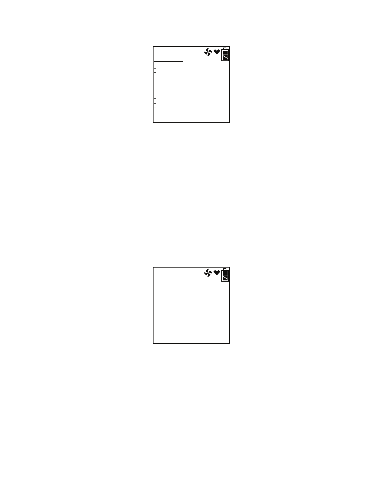
unit will enter Leak Check Mode.
13.The GX-2012 is now operating in Leak Check Mode.
LEAK CK MODE
CH4
F. S .
0
5000
ppm
ppm
The combustible gas reading is displayed along with the battery charge
level.
Performing a Fresh Air Adjustment, Leak Check Mode
Before using the GX-2012 for leak checking, it is recommended to set the
fresh air reading by performing a fresh air adjustment. This will set the
combustible gas channel to zero.
1. Find a fresh-air environment. This is an environment free of toxic or
combustible gases and of normal oxygen content (20.9%).
2. Turn on the unit as described above in “Turning On the GX-2012, Leak
Check Mode” on page 84.
3. Press and hold the AIRS button. The display will prompt you to hold the
AIRS button.
AIr
CAL
HOLD AIR
4. Continue to hold the AIRS button until the display prompts you to
release the AIRS button. The GX-2012 will set the fresh air reading for
the combustible channel. Once the fresh air adjustment has finished, start
up is complete and the unit is ready for leak testing.
5. If you would like to calibrate the GX-2012 while in Leak Check Mode,
follow the same instructions described in “Calibration Mode” on page 57.
90 • Start Up, Leak Check Mode GX-2012 Operator’s Manual
Page 99

Leak Testing
In Leak Check Mode, the GX-2012 only displays combustible gas readings.
The increment of the reading is always 100 ppm but the display range can be
adjusted by using the DISPLAY (ADJ) button. The display range choices are
500 ppm, 1000 ppm, 2000 ppm, and 5000 ppm. The readings are displayed in
both numerical and bar graph form. As the gas concentration increases from
0 ppm, the alarm LEDs begin to blink in unison with the buzzer’s pulsing.
The blinking/pulsing rate increases as the gas reading increases. If desired the
buzzer can be turned off in Leak Check Mode.
In a low-light environment, press and release any of the buttons to turn on the
display backlight. If BEEP. SET is turned on in Maintenance Mode, the GX-
2012 beeps once every 5 minutes to confirm that it’s operating.
Setting the Display Range Value
The GX-2012 Leak Check Mode has 4 display range ppm values to choose
from: 500 ppm, 1000 ppm, 2000 ppm, and 5000 ppm.
NOTE: The GX-2012 is always detecting combustible gas up to 5000 ppm.
The display range value is only adjusting what part of the detection
range is displayed on the LCD.
To change the display range value:
1. While in Leak Check Mode, press and release the DISPLAY (ADJ)
button. The display range value displayed along the bottom of the screen
will change.
LEAK CK MODE
CH4
F. S .
0
500
ppm
ppm
Continue to press and release the DISPLAY (ADJ) button until the desired
display range value is displayed.
2. The unit is now operating with the selected display range.
Locating a Leak
1. Start up the GX-2012 as described above in “Turning On the GX-2012,
Leak Check Mode” on page 84.
GX-2012 Operator’s Manual Leak Testing • 91
Page 100

2. Move the probe tip or tapered nozzle tip back and forth along the area
where a leak is suspected.
3. Observe the display reading. If the gas level increases, the numerical
reading will increase, the bar graph level will increase, and the beeping
and buzzer pulsing frequency will increase.
4. Your gas reading may exceed your display range or 100% LEL. For a
description of both scenarios, see the following section.
5. Use the increasing and decreasing of the reading to locate the leak point.
6. To exit Leak Check Mode and return to the Leak Check Mode Select
Screen at any time, press and hold the (SHIFT)T button for 5 seconds.
Overscale Conditions
There are three overscale conditions that the GX-2012 may experience while
operating in Leak Check Mode.
• Exceeding display range
If you are using a display range of 500, 1000, or 2000 ppm and the gas
level goes above the display range, the full scale value of the display
range will be displayed but it will not be an overscale condition unless the
gas level is above 5000 ppm.
• Exceeding 5000 ppm
If the combustible gas level exceeds 5000 ppm, the GX-2012 will display
an overscale condition but will continue displaying the gas reading in
%LEL.
LEAK CK MODE
CH4
OVER
32
5000
%LEL
ppm
92 • Leak Testing GX-2012 Operator’s Manual
 Loading...