

Page 1

Model GD-K7D2 (24 VDC)
Sample Draw Detector
Operator’s Manual
Part Number: 71-0078RK
Revision: A
Released: 3/1/11
www.rkiinstruments.com
Page 2

WARNING
Read and understand this instruction manual before operating
detector . Improper use of the dete ctor could result in bodily harm
or death.
Periodic calibration and maintenance of the detector is essential
for proper operation and correct readings. Please calibrate and
maintain this detector regularly! Frequency of calibration
depends upon the type of use you have and the sensor types.
T ypical calibration frequencies for most applications a re between
3 and 6 months, but can be required more often or less often
based on your usage.
Model GD-K7D2 (24 VDC) Sample Draw Transmitter
Page 3

Product Warranty
RKI Instruments, Inc. warrants gas alarm equipment sold by us to be free from defects in
materials, workmanship, and performance for a period of one year* from the date of
shipment from RKI Instruments, Inc. Any parts found defective within that period will be
repaired or replaced, at our option, free of charge. Parts must be returned to RKI
Instruments, Inc. for repair or replacement. This warranty does not apply to those items
which by their nature are subject to deterioration or consumption in normal service, and
which must be cleaned, repaired or replaced on a routine basis. Examples of such items
are:
a) Pump diaphragms and valves c) Batteries
b) Fuses d) Filter elements
Warranty is voided by abuse including mechanical damage, alteration, rough handling, or
repair procedures not in accordance with instruction manual. This warranty indicates the
full extent of our liability, and we are not responsible for removal or replacement costs,
local repair costs, transportation costs, or contingent expenses incurred without our prior
approval.
THIS WARRANTY IS EXPRESSLY IN LIEU OF ANY AND ALL OTHER
WARRANTIES AND REPRESENTATIONS, EXPRESSED OR IMPLIED, AND
ALL OTHER OBLIGATIONS OR LIABILITIES ON THE PART OF RKI
INSTRUMENTS, INC. INCLUDING BUT NOT LIMITED TO, THE WARRANTY OF
MERCHANTABILITY OR FITNESS FOR A PARTICULAR PURPOSE. IN NO
EVENT SHALL RKI INSTRUMENTS, INC. BE LIABLE FOR INDIRECT,
INCIDENTAL OR CONSEQUENTIAL LOSS OR DAMAGE OF ANY KIND
CONNECTED WITH THE USE OF ITS PRODUCTS OR FAILURE OF ITS
PRODUCTS TO FUNCTION OR OPERATE PROPERLY.
This warranty covers instruments and parts sold to users only by authorized distributors,
dealers and representatives as appointed by RKI Instruments, Inc.
We do not assume indemnification for any accident or damage caused by the operation of
this gas monitor and our warranty is limited to the replacement of parts or our complete
goods. Warranty covers parts and labor performed at RKI Instruments, Inc. only, and does
not cover field labor or shipment of parts back to RKI.
Model GD-K7D2 (24 VD C) Sample D raw Transmitt er
Page 4

Table of Contents
Overview . . . . . . . . . . . . . . . . . . . . . . . . . . . . . . . . . . . . . . . . . . . . . . . . . . . . . . . . . . . . . . . . . . . 1
Specifications. . . . . . . . . . . . . . . . . . . . . . . . . . . . . . . . . . . . . . . . . . . . . . . . . . . . . . . . . . . . . . . . 1
Description. . . . . . . . . . . . . . . . . . . . . . . . . . . . . . . . . . . . . . . . . . . . . . . . . . . . . . . . . . . . . . . . . . 2
Cover. . . . . . . . . . . . . . . . . . . . . . . . . . . . . . . . . . . . . . . . . . . . . . . . . . . . . . . . . . . . . . . . . . . . . . . . . . . . . . . . 2
Detection Unit . . . . . . . . . . . . . . . . . . . . . . . . . . . . . . . . . . . . . . . . . . . . . . . . . . . . . . . . . . . . . . . . . . . . . . . . 3
Installation Bracket. . . . . . . . . . . . . . . . . . . . . . . . . . . . . . . . . . . . . . . . . . . . . . . . . . . . . . . . . . . . . . . . . . . . 5
Installation . . . . . . . . . . . . . . . . . . . . . . . . . . . . . . . . . . . . . . . . . . . . . . . . . . . . . . . . . . . . . . . . . . 7
Disassembling the GD-K7D2 . . . . . . . . . . . . . . . . . . . . . . . . . . . . . . . . . . . . . . . . . . . . . . . . . . . . . . . . . . . 7
Mounting the GD-K7D2. . . . . . . . . . . . . . . . . . . . . . . . . . . . . . . . . . . . . . . . . . . . . . . . . . . . . . . . . . . . . . . . 7
Connecting Sample Lines to the GD-K7D2. . . . . . . . . . . . . . . . . . . . . . . . . . . . . . . . . . . . . . . . . . . . . . . . 8
Wiring the GD-K7D2 . . . . . . . . . . . . . . . . . . . . . . . . . . . . . . . . . . . . . . . . . . . . . . . . . . . . . . . . . . . . . . . . . 10
Assembling the GD-K7D2. . . . . . . . . . . . . . . . . . . . . . . . . . . . . . . . . . . . . . . . . . . . . . . . . . . . . . . . . . . . . 12
Startup. . . . . . . . . . . . . . . . . . . . . . . . . . . . . . . . . . . . . . . . . . . . . . . . . . . . . . . . . . . . . . . . . . . . . 12
Introducing Incoming Power . . . . . . . . . . . . . . . . . . . . . . . . . . . . . . . . . . . . . . . . . . . . . . . . . . . . . . . . . . 12
Setting the Zero Signal. . . . . . . . . . . . . . . . . . . . . . . . . . . . . . . . . . . . . . . . . . . . . . . . . . . . . . . . . . . . . . . . 12
Operation . . . . . . . . . . . . . . . . . . . . . . . . . . . . . . . . . . . . . . . . . . . . . . . . . . . . . . . . . . . . . . . . . . 13
Normal Operation . . . . . . . . . . . . . . . . . . . . . . . . . . . . . . . . . . . . . . . . . . . . . . . . . . . . . . . . . . . . . . . . . . . 13
Low Flow Alarm. . . . . . . . . . . . . . . . . . . . . . . . . . . . . . . . . . . . . . . . . . . . . . . . . . . . . . . . . . . . . . . . . . . . . 13
Maintenance. . . . . . . . . . . . . . . . . . . . . . . . . . . . . . . . . . . . . . . . . . . . . . . . . . . . . . . . . . . . . . . . 14
Preventive Maintenance . . . . . . . . . . . . . . . . . . . . . . . . . . . . . . . . . . . . . . . . . . . . . . . . . . . . . . . . . . . . . . 14
Troubleshooting . . . . . . . . . . . . . . . . . . . . . . . . . . . . . . . . . . . . . . . . . . . . . . . . . . . . . . . . . . . . . . . . . . . . . 15
Storing the GD-K7D2 . . . . . . . . . . . . . . . . . . . . . . . . . . . . . . . . . . . . . . . . . . . . . . . . . . . . . . . . . . . . . . . . . 17
Replacing Components of the GD-K7D2 . . . . . . . . . . . . . . . . . . . . . . . . . . . . . . . . . . . . . . . . . . . . . . . . 17
Calibration Frequency . . . . . . . . . . . . . . . . . . . . . . . . . . . . . . . . . . . . . . . . . . . . . . . . . . . . . . . 19
Calibration . . . . . . . . . . . . . . . . . . . . . . . . . . . . . . . . . . . . . . . . . . . . . . . . . . . . . . . . . . . . . . . . . 20
Preparing for Calibration. . . . . . . . . . . . . . . . . . . . . . . . . . . . . . . . . . . . . . . . . . . . . . . . . . . . . . . . . . . . . . 20
Setting the Zero Reading. . . . . . . . . . . . . . . . . . . . . . . . . . . . . . . . . . . . . . . . . . . . . . . . . . . . . . . . . . . . . . 21
Setting the Response Reading. . . . . . . . . . . . . . . . . . . . . . . . . . . . . . . . . . . . . . . . . . . . . . . . . . . . . . . . . . 21
Parts List . . . . . . . . . . . . . . . . . . . . . . . . . . . . . . . . . . . . . . . . . . . . . . . . . . . . . . . . . . . . . . . . . . . 22
Model GD-K7D2 (24 VDC) Sample Draw Transmitter
Page 5

Overview
This manual describes th e 24 VDC vers ion of the Model GD-K7D 2 sample d raw 4 - 20 m A
transmitter detector head. This manual also describes how to install, start up, maintain,
and calibrate the GD-K7D2 when it is used with a gas monitoring controller. A parts list at
the end of this manual lists replacement parts and accessories for the GD-K7D2.
Specifications
Table 1 lists specif ications for the 24 VDC version of the GD-K7D2.
Table 1: Specifications
Target Gas & Detector Range Refer to the RKI Instruments Inc. List of Detectable Gasses
Area Classification Indoor, non-hazardous locations
Sampling Method Sample-draw
Input Power 24 VDC
Signal Output 4 to 20 mA
Response Time 90% in 60 seconds
Accuracy ± 10% of reading or ± 5% of full scale (whichever is greater)
Flow Rate Approximately 0.5 liters/minute
Recommended Sample Tubing 4 mm I.D. x 6 mm O.D. Teflon PTFE
Recommended Sample Tubing Length See Table 2 in the Installation section on p. 10
WARNING: When using the GD-K7D2, you must follow the instructions and warnings
in this manual to assure proper and safe operation of the GD- K7D2 and to
minimize the risk of personal injury. Be sure to maintain and period ically
calibrate the GD-K7D2 as described in this manual.
Model GD-K7D2 (24 VDC) Sample Draw Transmitter • 1
Page 6
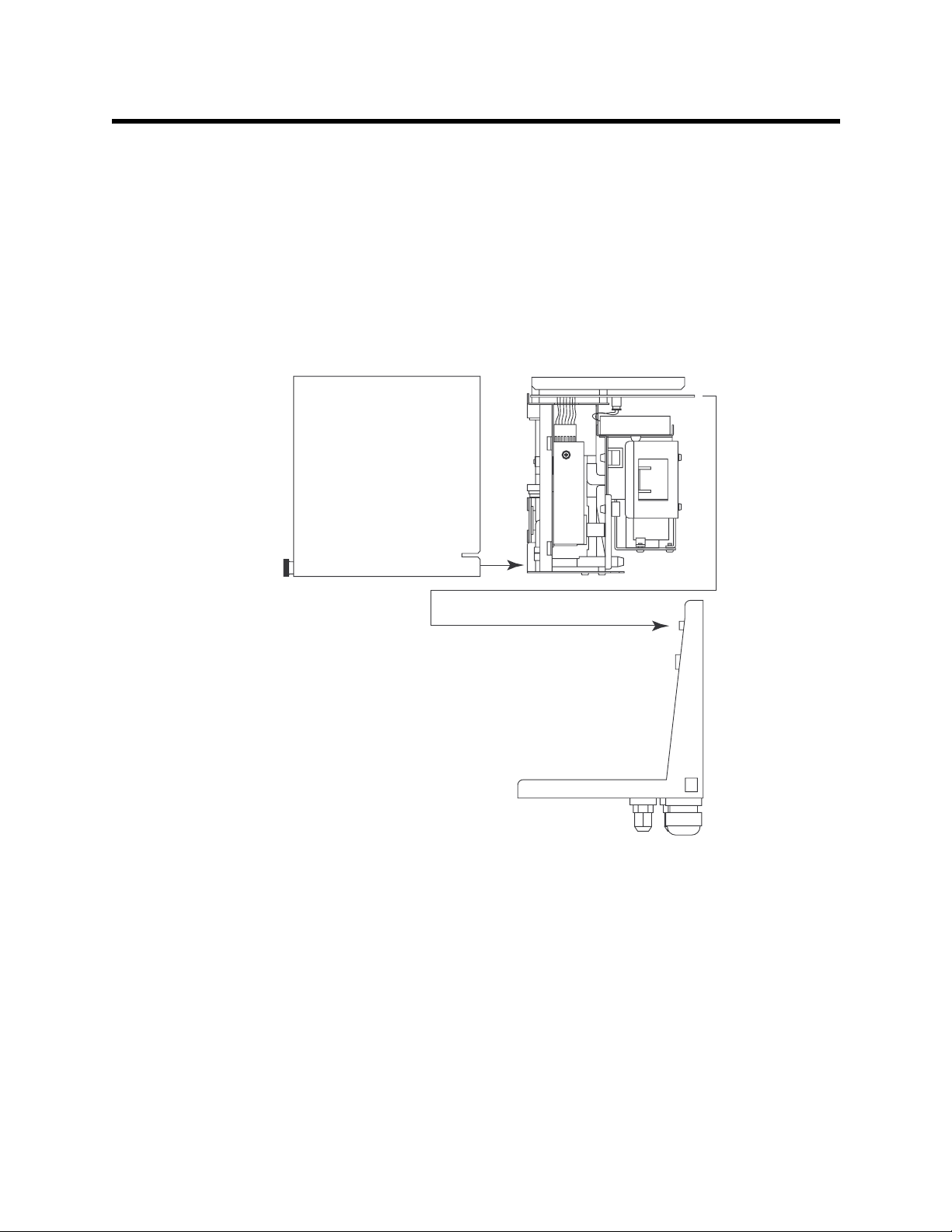
Description
This section describes the components of the GD-K7D2. The GD-K7D2 consists of three
separate sections: the cover, the detection unit, and the installation bracket. The detection
unit (front section) includes the flow system and gas detection components. The L-shaped
installation bracket (rear section) includes install ation components including a terminal
strip, tube fittings and a card edge connector socket.
The detection unit and installation bracket are secured together by a captive screw located
in the bottom right of the detection unit. The detection unit’s main circuit board plugs into
the socket on the installation bracket. The socket is above the terminal strip.
Detection Unit
Cover
Installation Bracket
Figure 1: Sections of the GD-K7D2
A hydrophobic sample filter is also provided with the GD-K7D2 for inst allation near the
sample in fitting. The filter scrubs particulates out of the sample stream and keeps water
and many other liquids from entering the GD-K7D2 flow system.
Cover
The painted steel cover slides over both the detection unit and installation brack et. It is
radio frequency (RF)- and dust-resistant. A thumbscrew on the front of the cover near the
bottom secures the cover to the installation bracket (see Figure 1). The cover includes a
label on the front that indicates the target gas and detection range of the GD-K7D2.
2 • Model GD-K7D2 (24 VDC) S ample Draw Transmit ter
Page 7
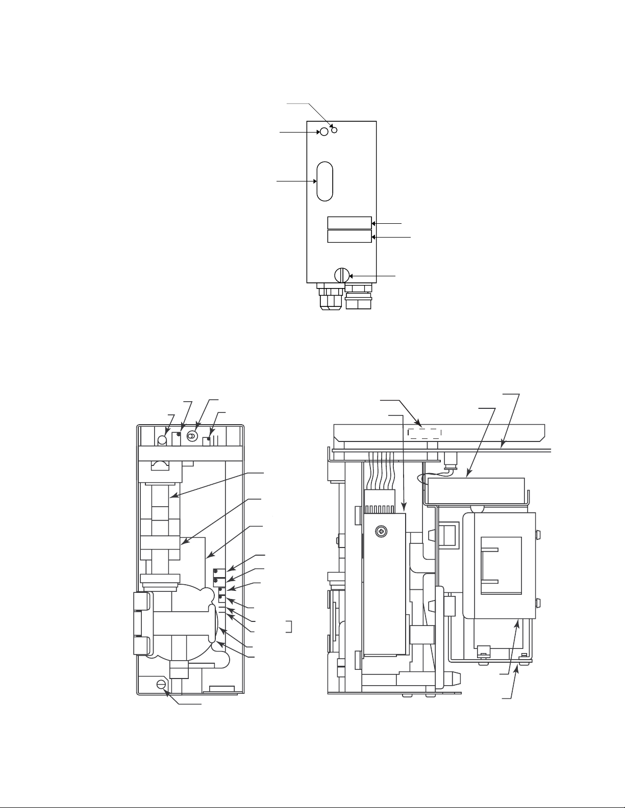
The flow light and flowmeter are visible through the cover. The flow rate potentiometer
Main Circuit Board
(pot) is accessible through the cover.
Flow rate
potentiometer
Flow light
Flowmeter
ADJ.
FLOW
GAS DETECTOR MODEL
ID card holder
Gas name
card holder
GD-K7D
Thumbscrew
Figure 2: GD-K7D2 Cover Components
Detection Unit
The detection unit includes the main circuit board, flowmeter, gas sensor, amplifi e r,
pump, and lithium battery pack.
Flow Rate Pot
Flow Light
ON/OFF Switch
Factory Adjust Pot
Fuse
Amplifier
Lithium Battery
Pack
Flowmeter
Low Flow
Sensor
Gas Sensor
Span Pot
Zero Pot
Gain Pot
(Factory Adjust)
Factory Adjust Pot
TP1 (+)
TP2 (+)
Sample Adapter
Sensor Retaining
Clamp
Captive Retaining Screw
Figure 3: Detection Unit Component Location
mA
Output
Pump
Bracket
Pump
Model GD-K7D2 (24 VDC) Sample Draw Transmitter • 3
Page 8

Main Circuit Board
The main circuit board includes the flow light, flow rate pot, ON/OFF switch and fuse.
The end of the board at the rear of the detection unit plugs into a socket on the installation
bracket.
Flow light
The flow light is at the top left corner of the detection unit (s ee Fi gure 2 and 3) . The green
flow light is on when the GD-K7D2’s flow rate is at an acceptable flow rate. If the flow rate
drops below or rises above the acceptable flow rate, the flow light turns off.
Flow rate pot
The flow rate pot is to the right of the flow light (see Figure 2 and 3). You can adjust the
GD-K7D2’s flow rate with the flow rate pot. The pot is accessible through a hole in th e
cover.
ON/OFF switch
The ON/OFF switch is to the right of the flow rate pot (see Figure 3). The On/Off switch
turns the GD-K7D2 on an d o f f. The switch is in the ON position when the toggle switch is
in the right position.
Fuse
A 2 amp, 5 mm x 20 mm fuse is located on the middle left of the main board. It is
accessible by removing four screws that retain a metal cover over the main board.
Flowmeter
The flowmeter is below the flow light (see Figure 2 and 3). A ball in the flowmeter colu mn
indicates the flow rate of the GD-K7D2. Two horizontal lines on the flowmeter mark the
acceptable flow rate for the GD-K7D2. Use the flow rate pot to keep the flowmeter ball
between the two lines. A flow sensor at the bottom of the flowmeter senses when the
flowmeter ball is low enough to be at the bottom of the flowmeter and initiates a low flow
alarm.
Gas Sensor
The gas sensor is below and to the right of the flowmeter (see Figure 3). Through a series
of electrical and chemical reactions, the gas sensor produces an electrical current that is
proportional to the detection range of the target gas in the test sample. Electrodes within
the gas sensor housing are surrounded by liquid electrolyte. The chemical and electrical
reactions are facilitated by the electrolyte.
A sample adapter is attached to the front of the sensor. It directs the sample over a gas
permeable membrane on the front of the sensor and into the sensor.
Amplifier
The amplifier is to the right of the sensor (see Figure 3). The amplifier converts the output
of the sensor to a 4 to 20 mA signal (that is proportional to the detection range of the GDK7D2) and transmits the signal to a controller. The amplifier includes the span pot, zero
pot, gain pot, and output check pins.
Span pot
The span pot is at the top of the amplifier. Use the span pot to adjust the GD-K7D2’s
response output during the calibration procedure.
Zero pot
The zero pot is below the span pot. Use the zero pot to adjust the GD-K7D2’s fresh air
4 • Model GD-K7D2 (24 VDC) S ample Draw Transmit ter
Page 9
output during start-up and calibration procedures.
Gain pot
The gain pot is below the zero pot. It is used to make coarse span adjustments. The ga in
pot is factory set and for adjustment by a field service technician only.
Another factory adjust pot is located below the gain pot. Do not adjus t this pot.
Output check pins
Two output check pins [marked 1 (+) and 2 (-)] are below the pots. Use the output check
pins to read the signal output of the GD-K7D2 with a milliampmeter during the start-up
and calibration procedures.
Pump
The pump is behind the sensor. The pump pulls the test sample into the GD-K7D2. The
pump operates on AC voltage that is generated by the GD-K7D2 from the 24 VDC input
power.
Lithium Battery Pack
A 3.6 volt lithium battery pack is above the pump on the right s ide of the GD - K7 D2. The
lithium battery pack maintains a bias voltage on the gas sensor when the GD-K7D2 is not
receiving incoming power, such as during shipment or storage. If the GD-K7D2 is off
power for an extended period and the lithium battery pack is dead, the gas sensor
operation will be affected when the GD-K7D2 is started up. See Storing the GD-K7D2 in
the Maintenance section for battery pack replacement recommendations.
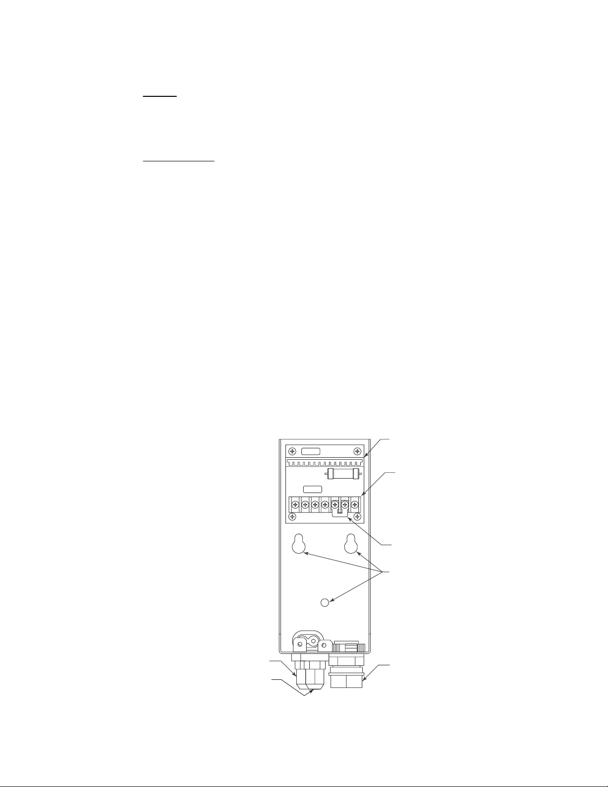
Installation Bracket
The L-shaped installation bracket facilitates mounting and wiring of the GD-K7D2. The
three mounting holes on the back of the bracket are used to mount it to a vertical surface.
The installation bracket includes the socket, external wiring terminal strip, cable bushing,
and sample fittings.
Socket for
Main Board
External Wiring
Terminal Strip
Jumper is factory installed when
*
GD-K7D2 is used with a controller
that does not have a built in flow
alarm circuit and flow alarm
wiring terminals.
Gas Out
SampleFitting
Gas In
Sample Fitting
Factory Installed
Jumper
*
Mounting Holes
Cable Bushing
Figure 4: Installation Bracket Co mponent Location
Model GD-K7D2 (24 VDC) Sample Draw Transmitter • 5
Page 10

Socket
A card edge connector socket on the back of the bracket mates with the main circuit board
on the detection unit.
External Wiring Terminal Strip
A seven point terminal strip is located below the socket and used for wiring the GD-K7D2
to a controller.
A jumper is normally factory installed between the second and third terminals from the
right. This jumper is installed when the GD-K7 D2 is used with a controller that does not
have a flow alarm circuit and flow alarm terminals for wiring to the GD-K7D2. It is not
installed when the GD-K7D2 is used with a controller that has flow alar m circuitry and
flow alarm terminals. See Wiring the GD-K7D2 to a Controller in the Installation section
for both types of wiring.
Cable Bushing
The 1/2 in. (1.25 cm) cable bushing on the bottom of the bracket allows you to route
wiring from a controller to the seven point external wiring terminal strip on the back of
the bracket.
Gas In & Gas Out Sample Fittings
There are two tube fittings on the bottom of the bracket, the gas in and gas out sample
fittings. The gas in fitting is forward of the gas out fitting. The gas in fitting allows sample
to enter the GD-K7D2 and the gas out fitting is for exhausting the sample. Both fittings
accept 6 mm O.D. x 4 mm I.D. Teflon PTFE tubing.
6 • Model GD-K7D2 (24 VDC) S ample Draw Transmit ter
Page 11

Installation
This section describes how to install the GD-K7D2 at the monitoring site. This section
includes procedures to disassemble the GD-K7D2, mount the GD-K7D2, connect sample
lines to the GD-K7D2, and wire the GD-K7D2 to a controller.
Disassembling the GD-K7D2
1. Loosen the thumbscrew on the front of the housing cover, then remove the cover fr om
the detection unit and installation brac ket.
2. Loosen the captive screw in the lower left front of the detection unit that secures it to
the installation bracket.
3. Pull the detectio n unit away from the installation bracket until the ma in board
disengages from the socket, then lift it up slightly to free the detection unit from the
installation bracket.
Mounting the GD-K7D2
CAUTION: The GD-K7D2 is suitable for installation in indoor areas where general purpose
equipment is in use.
1. Select a mounting site that is representative of the monitoring environment. Consider
the following when you select the mounting site.
• Select a site that is easily accessible for servicing.
• Select a site where the GD-K7D2 is not likely to be bumped or disturbed. Make
sure there is sufficient room to make wiring and sample line connections at the
bottom of the GD-K7D2. Also make sure there is sufficient room to perform
start-up, maintenance, and calibration procedures.
• Select a site near the sampling area. The GD-K7D2 is designed to detect a variety
of toxic gases many of which are easily absorbed in sample tubing. See Table 2
below for recommended sample tubing lengths for various gases when using
Teflon PTFE sample tubing. Contact RKI Instruments, Inc. for gases not listed.
Table 2: Maximum Sample Tubing Lengths For Various Gases
Target Gas
BF
(HF), ClF3, ClO2, F2, HF, O3, POCl3 (HCl), WF6, TaF5 (HF) 5 meters
3
(HCl), BR2, HBr, HCl, F2, NO, NO2, PCl3 (HCl), POCl3,
BCl
3
SbCl
(HCl), SiH2Cl2 (HCl), SnCl4 (HCl), SiCl4 (HCl), SO2, TiCl4
5
Maximum Sample
Tubing Length
10 meters
(HCl)
Cl
, Si2H
2
6
20 meters
, B2H6, CO, H2S, NH3, PH3, SiH
AsH
3
Note: Gas in parenthesis indicates brea kdown product of target gas being detected.
4
30 meters
2. Use three #10 screws through the three mounting holes in the inst all ati on bracket to
mount the installation bracket to a vertical surface. One of the mounting holes is
round and the other two are slotted (See Figure 5).
Model GD-K7D2 (24 VDC) Sample Draw Transmitter • 7
Page 12

FLOW
NOTE: All measurements in inches
2.76
ADJ.
6.46
7.5
FRONT VIEW
GAS DETECTOR MODEL
GD-K7D
6.02
.59
1.57
1.38
REAR VIEW
1.97
1.54
0.36
Figure 5: Mounting the GD-K7 D2
Connecting Sample Lines to the GD-K7D2
1. When shipped from the factory, the tube nu t, ferrule, and tube insert are shipped
uninstalled and the open fittings are plugged with protective rubber plugs. Rem ove
the protective plugs from the gas in and gas out fittings.
2. Install a short piece, up to 20 cm long, of 4 mm I.D. x 6 O.D. mm Teflon PTFE sample
tubing to the gas in fitting as shown in Figure 6 below.
8 • Model GD-K7D2 (24 VDC) S ample Draw Transmit ter
SIDE VIEW
Page 13

Tubing Insert
Ferrule
Tube Nut
4 mm x 6 mm
PTFE T eflon Tubing
Figure 6: Installing Tubing in the Sample Fittings
3. Connect the sample filter to the tube. The sample filter has flexible tube stubs on each
end. Push one end onto the sample tube.
4. Connect another length of sample tubing to the other side of the sample filter and
route it to the sampling area. Be sure not to exceed the maximum sample tubing
length listed in Table 2.
20 cm Max
Sample In Fitting
Sample Filter
To Sample Area
Figure 7: Installing the Sample Filter
Model GD-K7D2 (24 VDC) Sample Draw Transmitter • 9
Page 14

CAUTION: Avoid loops or slumps in the incoming sample line. T o reduce response time, keep the
incoming sampl e line as sh ort as poss ible. See the Table 2 above for maxi mum sampl e
tubing lengths.
5. Attach 4 mm I.D. x 6 mm O.D. Teflon P TFE sample tubing to the gas out fitting. Route
the opposite end of the tubing to an open area where the sample can safely disperse or
to an exhaust duct.
Wiring the GD-K7D2 to a Controller
W ARNING: Always verify that power to the GD-K7D2 and to the controller are off and
that the controller’s and GD-K7D2’s power switches are in the off position
before making wiring connections or adjustments.
1. Turn off power to the controller and the GD-K7D2.
2. Place the controller’ s and GD-K7D2’s power swit ches in the OFF position.
3. Guide a three or six conductor shielded cable through the cable bushing at the bottom
of the GD-K7D2 installatio n unit.
A three conductor cable is used when the GD-K7D2 is wired to a controller that does
not have flow alarm circuitry and flow alarm terminals for connection to the GDK7D2 (see Figure 8 below). In this case, a jumper is factory installed between the
second and third terminals from the right and the fourth and seventh terminals from
the right. If these jumpers are not installed and the GD-K7D2 is being connected to a
controller without flow alarm termin als, install 20 gauge wire to make these ju mper
connections.
A six conductor cable is used when the controller has flow alarm circuitry and flow
alarm terminals for connecti on to the GD-K7D2 (see Figure 9 below).
CAUTION: Leave the cable shield’s drain wire insulated and disconnected at the GD-K7D2. You
will connect the opposite end of the cable shield’s drain wire at the controller.
4. Connect three or four wires between the GD-K7D2 and the controller as shown in
Figure 8 or Figure 9 depending on the controller used.
CAUTION: At the controller, do not ro ute power and GD-K7D2 wiring t hrough the same
conduit hub. The power cable may di srupt the transmission of the GD-K7D2’s
signal to the controller.
NOTE: The controller connections shown are typical. See the controller Detector Head
Specification Sheet for the GD-K7D2 or a controller specific wiring diagram for
the GD-K7D2 for connections specific to the controller.
10 • Model GD-K7D2 (24 VDC) Sample Draw Transmi tter
Page 15

5. If using a controller with flow alarm terminals, connect the remaining two wires to an
appropriate 24 VDC power source as shown in Figure 9.
4-20 mA
DC24V
+
FLOW
ALARM
+
External Wiring
Terminal Strip
Factory Installed Jumper
Cable Shield
Controller , T ypical
4 - 20 mA In (FB)
- (DC Ground)
+ 24 VDC
Figure 8: Wiring the GD-K7D2 to a Controller Without Flow Alarm Terminals
DC24V
+
FLOW
ALARM
4-20 mA
+
External Wiring
Terminal Strip
Cable Shield
Controller , T ypical
4 - 20 mA In (FB)
+ 24 VDC
Flow Alarm
24 VDC
Figure 9: Wiring the GD-K7 D 2 to a Controller With Flow Alarm Te rminals
6. Connect the ground terminal to a locally availabl e earth ground.
Model GD-K7D2 (24 VDC) Sample Draw Transmitter • 11
Page 16

Start Up
7. Connect the cable shield’s drain wire to an available earth (chassis) ground at the
controller. The grounding screw on each controller conduit hub is an example of an
earth (chassis) ground.
Assembling the GD-K7D2
1. Position the det ect ion unit so the unit’s main circuit board is aligned with the socket
near the top of the installation unit and the interna l plumbing is aligned near the
bottom of each unit.
2. Push the detection unit into the installation bracket so the main circuit board plugs
into the socket.
3. Tighten the captive screw in the lower left of the detection unit that secures the
detection unit to the installation bracket.
This section describes procedures to start up the GD-K7D2 and place it into normal
operation.
Introducing Incoming Power
1. Complete the installation procedures described earlier in this manual.
2. Verify that the power wiring is correct and secure for the GD-K7D2 and the contro l le r.
3. Turn on or plug in the incoming power to the controller.
4. Turn on the controller
5. If providing 24 VDC from a source other than the controller (see Figure 9), turn on or
plug in the incoming DC power to the GD-K7D2.
6. Place the GD-K7D2’s power switch in the ON position.
7. Verify that the flowmeter ball is between the two lines on the flowmeter. If necessary,
use the flow rate potentiometer to adjust the flow rate, so the flowmeter ball is
between the two lines.
8. Verify that the incoming sample line is not leaking. To test the sample line, plug the
open end of the sample line with your thumb. If the flowmeter ball drops to the
bottom of the flowmeter, the incoming sample line is not leaking.
CAUTION: Allow the GD-K7D2 to warm up for 30 minutes (2 hours for ammonia units) before
you continue with the next section. If the lithium battery pack is dead and the GDK7D2 has been off po wer for an extend ed period of time , allow the GD-K7D2 to
warm up overnight.
Setting the Zero Signal
CAUTION: If you suspect the presence of toxic g as in the monitoring environment, use the
calibration kit and the zero air calibration cylinder to introduce “fresh air” to t he
sensor and verify an accurate zero setting.
1. Verify that the GD-K7D2 is in a fresh air environment (environment known to be free
of toxic and combustible gas and of normal oxygen content, 20.9%).
2. Unscrew the captive thumbscrew on the front of the cover and remove the cover from
the GD-K7D2.
12 • Model GD-K7D2 (24 VDC) Sample Draw Transmi tter
Page 17

Operation
3. Use small test clips to connect a milliampmeter to the output check pins.
4. Verify a reading of 4.0 mA on the milliam pmeter. If necessary, use the zero pot to
adjust the milliampmeter reading to 4.0 mA.
CAUTION: Do not adjust the span pot at this time unless a full calibra t ion is performed. The
GD-K7D2 is factory calibrated before shipment.
5. Remove the milli a m p me t e r test clips.
6. Slide the housing cover over the detection unit and ins tallation bracket, then tighten
the thumbscrew at the front of the cover to secure the cover to the installation bracket.
Normal Operation
During normal operati on , t he GD- K7D 2 w i ll draw sample from the sample area and se nd
the target gas reading to the controller via a 4 - 20 mA signal. The flowmeter ball should be
between the two red lines. If the flowmeter ball is out of the red lines, use the flow
adjustment pot to adjust the flow.
Low Flow Alarm
If the GD-K7D2’s flow rate drops low enough so that the flow ball is at the bottom of the
flowmeter, the GD-K7D2 will go into low flow alarm after a delay of about one minute.
When it is in low alarm, the flow light will turn off.
If the controller is the type that does not have flow alarm terminals, see Figure 8, then the
GD-K7D2 will interrupt the 4 - 20 mA signal to the controller. This will cause the
controller to indicate a fail alarm.
If the controller is the type that has flow alarm terminals, see Figure 9, then the GD-K7D2
will cause the controller to go into low flow alarm. See the controller instruction manual
for more information.
Model GD-K7D2 (24 VDC) Sample Draw Transmitter • 13
Page 18

Maintenance
This section describes maintenance procedures for the GD-K7D2. It includes preventive
maintenance and troubleshooting procedures.
Preventive Maintenance
This section describes a preventive maintenance schedule to ensure the optimum
performance of the GD-K7D2. It includes daily, monthly, and quarterly procedures.
Daily
1. Verify that the flow light on the front of the GD-K7D2 is on. If it is off, see the
2. Verify that the flowmeter ball is between the two lines on the flowmeter. If necessary,
3. Verify a display reading of 0 at the controller. Investigate significant changes in the
Monthly
Troubleshooting section below.
use the flow rate potentiometer to adjust the flow rate, so the flowmeter ball is
between the two lines.
display reading.
NOTE: Verifying the response of the GD-K7D2 may cause alarms. Be sure to put the
controller into it’s calibration program or disable external alarms before
verification.
This procedure describes a test to verify that the GD-K7D2 responds properly to the target
gas.
Preparing for the response test
1. Verify that the display reading for the channel you plan to test is 0.
If the display reading is not 0, set the zero reading of the GD-K7D2 as described in the
Start Up section of this manual, then continue this procedure.
2. Assemble the calibra tion kit as described in the Calibration section of this manual.
NOTE: Do not connect the tubing from the GD-K7D2’s gas in fitting to the regulator at
this time.
3. Loosen the thumbscrew on the front of the cover, then remove the cover from the
detection unit and installation bracket.
4. Use small test clips to connect a milliampmeter to the output check pins.
5. Use the following formula to determine the correct GD-K7D2 (response) output for
the calibrating sample.
Response Output (mA) = (calibrating gas/fullscale) X 16 + 4
For example, if you have a cylinder of 5 ppm ca libration gas with a GD-K7D2 full
scale of 10 ppm:
12 mA = (5 ppm/10 ppm) X 16 + 4
14 • Model GD-K7D2 (24 VDC) Sample Draw Transmi tter
Page 19

Performing the response test
NOTE: This procedure describes a response test using the RKI calibration kit that
incudes a “demand flow” regulato r. A calibration kit that uses a gas collection
bag is also available. Contact RKI Inst rume nts, Inc., for more information
concerning the gas collection bag accessory.
1. Disconnect the incoming Teflon sample tubing from the sam ple filter.
2. Connect the calibration kit sample tubing from the regulator to the sample filter.
The GD-K7D2’s pump automatically begins pulling the gas from the calibration
cylinder when you connect the GD-K7D2’s sample filter to the regulator.
3. Allow gas to flow for two minutes and verify the reading is within ± 20% of the
response reading you determined earlier.
NOTE: If the reading is not within ± 20% of the correct response reading, calibrate the
GD-K7D2 as described in the Calibration section of this manual.
4. Disconnect the cali bration kit sample tubing from the sample filter.
5. Disconnect the cali bration kit sample tubing from the regulator, then remove the
milliampmeter test clips from the output check pins.
6. Reinstall the incoming Teflon sample tubing to the sample fi lter.
7. Slide the cover over the detection unit and installation bracket, then tighten the
thumbscrew at the front of the cover to secure it.
8. Disassemble the calibration kit as described in the Calibration section of this insert.
9. Allow time for the gas reading to return to normal and return the controller to normal
operation.
NOTE: If the gas reading does not return to normal before returning the controller to
normal operation, unwanted alarms may occur.
Quarterly/Biannually
Calibrate the GD-K7D2 as described in the Calibration section of this manual. The
calibration frequency (every 3 to 6 months) depends on your specific application.
Troubleshooting
The troubleshooting guide describes symptoms, probable causes, and recommended
action for problems you may encounter with the GD-K7D2.
Fail Condition
Symptoms
• The GD-K7D2’s flow light is off.
Probable causes
• The GD-K7D2 wiri ng to the controller is disconnected or misco nnected.
• The 24 VDC to the GD-K7D2 is interrupted.
• The GD-K7D2’s flow rate is too low because of an obstructed sample line, failed
pump, etc.
Model GD-K7D2 (24 VDC) Sample Draw Transmitter • 15
Page 20

• The GD-K7D2’s ON/OFF switch is in the OFF position.
• The GD-K7D2 is mal functioning.
Recommended action
1. At the GD-K7D2, set the correct flow rate with flow rate potentiometer.
2. If you cannot set the correct flow rate, check the sample lines for obstructions or kinks.
3. Ve rify that the GD-K7D2 wiring is correct and secure. The Installation section of this
manual describes GD-K7D2 wiring connections.
4. Verify that the ON/OFF switch is in the ON position.
5. Verify that the 24 VDC to the GD-K7D2 is on and operational.
6. Calibrate the GD-K7D2 as described in the Calibration section of this manual.
7. If the fail condition continues, contact RKI Instruments, Inc. for further instruction.
Slow or No Response/Difficult or Unable to Calibrate
Symptoms
• The GD-K7D2 responds slowly or does not respond during the monthly response test.
• Unable to accurately set the zero or response reading during the calibration
procedure.
• The GD-K7D2 requires frequent calibration.
NOTE: Under “normal” circumstances, the GD-K7D2 requires calibration every 3 - 6
months. Some appli cations may require a more frequent calibration schedule.
Probable causes
• The calibration cylinder is low, out-dated, or defective.
• The GD-K7D2’s flow rate is too low because of obstructed sample line, failed pump,
etc.
• The GD-K7D2 is mal functioning.
Recommended action
1. Verify that the calibration cylinder contains an ade qu at e suppl y of a fresh test sample .
2. If necessary, set the correct flow rate with the flow adjust potentiometer.
3. If you cannot set the correct flow rate, check the sample line for obstructions or kinks.
4. If a demand flo w regulator is used for calibration, try a different demand flow
regulator or a gas bag setup and see if the calibration/response difficulties continue.
5. If the calibration/response difficulties continue, replace the sensor.
6. If the calibration/response difficulties continue, contact RKI Instruments, Inc. for
further instruction.
16 • Model GD-K7D2 (24 VDC) Sample Draw Transmi tter
Page 21

Storing the GD-K7D2
The GD-K7D2 has a circuit on the main board that keeps a bias voltage on the gas sensor
whenever there is no incoming power, such as during shipment, storage, or power
outages. This circuit is powered by the lithium battery pack. If the lithium battery pack is
dead when power to the GD-K7D2 is turned off or is lost, then the bias voltage normally
on the sensor during operation will not be applied to the sensor. If the sensor is without
the bias voltage for an extended period, it will take some time to stabilize and be ready for
use after power is restored. If the sensor is off bias for too long, it may not be usable when
power is restored.
The lithium battery pack will last approximately three years if the GD-K7D2 is on power
all the time, approximately 2 years if it is on power for eig ht hours a day, and
approximately 18 months if it is always off power. Be sure to replace the battery pack
periodically to assure that the sensor will always be on bias during power outages.
If the GD-K7D2 is going to be stored, make sure a fresh battery pack is installed to
maintain a bias on the sensor. See the next section for instructions to change the battery
pack.
In addition to keeping the sensor on bias during storage, it must be kept upright. If the
GD-K7D2 is stored, it must be oriented so that the sensor is upright.
WARNING: If the GD-K7D 2 is not stored in an upright position, the sensor membrane
which allows gas into the sensor may dry out and the sensor may not
recover proper operation.
Replacing Components of the GD-K7D2
Replacing the Fuse
1. Turn off the contro ller.
2. Turn off power to the controller.
3. If providing 24 VDC to the GD-K7D2 from a so urce other than the controller, turn off
the power source.
4. Place the GD-K7D2’s ON/OFF switch in the OFF position.
5. Unscrew the captive thumbscrew on the cover and remove the cover.
6. Remove the four flat head screws on the top of the detection unit that hol d down the
metal cover over the main board.
7. Remove the old fuse from the fuse clips and replace it with the new one. See the parts
list for the RKI part number for a replacement fuse.
8. Reinstall the metal main board cover with the four screws.
9. Rei nstall the GD-K7D2 cover.
10. Turn on pow er to the controller and turn on the controller.
11. If providing 24 VDC to the GD-K7D2 from a source other than the controller, turn on
the power source.
12. Place the ON/OFF switch in the ON position.
Replacing the Sensor
1. Turn off the contro ller.
2. Turn off power to the controller.
Model GD-K7D2 (24 VDC) Sample Draw Transmitter • 17
Page 22

3. If providing 24 VDC to the GD-K7D2 from a so urce other than the controller, turn off
the power source.
4. Place the GD-K7D2’s ON/OFF switch in the OFF position.
5. Loosen the thumbscrew on the front of the housing cover, then remove the cover fr om
the detection unit and installation brac ket.
6. Rotate the clear plastic cover on the right side of the detection unit towards you to
allow access to the amplifier and sensor.
7. A metal snap- in bracket holds the sensor in place. While facing the GD -K 7D2, push
this bracket to the left until it releases the sensor.
8. Gently push the sensor back, away from the sample cup, and slide it out of the right
side of the detector unit with the amplifier cable still connected to the amplifier. The
amplifier is attached to the sensor and will come out with the sensor.
9. Disconnect the amplifier cable from the amplifier. Gently pull on the connector to
disconnect it.
10. Remove the retaining screw near the top of the amplifier that holds the amplifier to
the sensor.
11. Disconnect the sensor connector at the bottom of the amplifier from the sensor by
gently pulling the bottom of the amplifier away from the sensor.
12. Install the amplifier onto the new sensor with the sensor connector and retaining
screw.
13. Connect the amplifier cable to the amplifier.
14. Reinstall the sensor into the sample cup.
15. Reinstall the sensor retaining bracket .
16. Reinstall the clear plastic cover on the right side of the detection unit.
17. Reinstall the GD-K7D2 cover.
18. Turn on pow er to the controller and turn on the controller.
19. If providing 24 VDC to the GD-K7D2 from a source other than the controller, turn on
the power source.
20. Place the ON/OFF switch in the ON position.
21. Calibrate the sensor as described in the Calibration section.
Replacing the Pump
1. Turn off the contro ller.
2. Turn off power to the controller.
3. If providing 24 VDC to the GD-K7D2 from a so urce other than the controller, turn off
the power source.
4. Place the GD-K7D2’s ON/OFF switch in the OFF position.
5. Loosen the thumbscrew on the front of the housing cover, then remove the cover fr om
the detection unit and installation brac ket.
6. Loosen the captive screw in the lower left front of the detection unit that secures it to
the installation bracket.
7. Pull the detectio n unit away from the installation bracket until the ma in board
disengages from the socket, then lift it up slightly to free the detection unit from the
installation bracket.
18 • Model GD-K7D2 (24 VDC) Sample Draw Transmi tter
Page 23

8. A metal snap-on bracket holds the pump in place. A tab on the bracket is accessible on
the right side of the detector unit. Push the bracket tab back and away from the pump
until the bracket snaps back and releases the pump .
9. Gently pull the pum p towards the back of the detector unit until it disengages from
the detector unit.
10. Disconnect the pump cable from the pump connector on the main board in the top of
the detector unit and remove the cable from cable retainer near the connector. Note
how the cable is routed to the connected.
11. Connect the new pump’s cable to the pump connector and route the cable through the
cable retainer like the old pump’s cable.
12. Install the new pump into the detector unit and snap the retaining bracket back on .
13. Reinstall the detector unit into the inst allation bracket.
14. Reinstall the GD-K7D2 cover.
15. Turn on pow er to the controller and turn on the controller.
16. If providing 24 VDC to the GD-K7D2 from a source other than the controller, turn on
the power source.
17. Place the ON/OFF switch in the ON position.
18. Verify that the flow ball in the flowmeter is between the two red lines. Adjust the flow
with the flow rate pot if necessary.
Replacing the Lithium Battery Pack
NOTE: Change the lithium battery pack with the controller on and the GD-K7D2 on
power and operating. If power to the GD-K7D2 is turned off to change the
battery pack, the gas readings may be unstable for a short time when power is
restored.
1. Loosen the thumbscrew on the front of the housing cover, then remove the cover fr om
the detection unit and installation brac ket.
2. Carefully pull the lithium battery pack away from the detector unit. It is installed in
the detector unit with a strip of Velcro tape.
3. Carefully disconnect the battery pack cable connector from the main board by pulling
it straight down, away from the main board. D o not touch the main board.
4. Carefully plug the cable connector from the new battery pack into the battery pack
connector on main board. Do not touch the main board.
5. Install the new battery pack in the detection unit.
6. Rei nstall the GD-K7D2 cover.
Calibration Frequency
Although there is no particular calibration frequency that is correct for all applications, a
calibration frequency of every 3 to 6 months is adequate for mo st applications. Unless
experience in a particular application dictates otherwise, RKI Instruments, Inc.
recommends a calibration frequency of every 3 months (quarterly).
If an application is not very demanding, for example detection in a clean, temperature
controlled environment, and calibration adjustments a re minima l at calibration, then a
Model GD-K7D2 (24 VDC) Sample Draw Transmitter • 19
Page 24

Calibration
calibration frequency of every 6 months is adequate.
If an application is very demanding, for example if the environment is not well controlled,
then more frequent calibration than every 3 months may be necessary.
This section describes how to calibrate the GD-K7D2. It includes procedures to prepar e for
calibration, set the zero reading, set the response reading, and return to normal operation.
Prepari ng for Ca libration
NOTE: This procedure describes calibration using the RKI calibration kit th at incudes a
“demand flow” regulator. A calibration kit that uses a gas collectio n bag is also
available. Contact RKI Instruments, Inc. for more information concerning the gas
collection bag accessory.
1. Put the controller into its cali bration program or disable external alarms to avoid
unwanted alarms during cali b ration.
2. Screw the regulator into the zero air calibration cyli nder.
NOTE: If you can verify that the GD-K7D2 is drawing sample from a fresh air
environment, you do not need to apply zero air to set the zero reading.
3. Disconnect the incoming Teflon sample tubing from the GD-K7D2’s sample filter.
4. Connect the calibration kit sample tubing to the sample filter.
NOTE: Do not connect the calibration kit sample tubing f rom the sample filter to the
regulator at this time.
5. Loosen the thumbscrew on the front of the cover, then remove the cover from the
detection unit and installation bracket.
6. Use small test clips to connect a milliampmeter to the output check pins.
7. Use the following formula to determine the correct GD-K7D2 (response) output for
the calibrating sample.
Response Output (mA) = (calibrating gas/fullscale) X 16 + 4
For example, if you have a cylinder of 5 ppm ca libration gas with a GD-K7D2 full
scale of 10 ppm:
12 mA = (5 ppm/10 ppm) X 16 + 4
20 • Model GD-K7D2 (24 VDC) Sample Draw Transmi tter
Page 25

Setting the Zero Reading
1. Connect the calibration kit sample tubing from the sample filter to the regulator.
NOTE: The GD-K7D2 pump automatically begin s pulling the calibrating sample from
the calibration cylinder when the calibration kit is completely assembled and
connected to the GD-K7D2’s sample filter.
2. Allo w t he GD-K7D2 to dr aw gas for two mi nutes and veri fy a reading of 4.0 mA . If
necessary, use the zero pot to adjust the reading to 4.0 mA.
3. Disconnect the cali bration kit sample tubing from the regulator, then unscrew the
regulator from the zero air calibration cylinder.
Leave the calibration kit sample tubing connected to the sample filter.
Setting the Response Reading
1. Screw the regulator into the calibration cylinder.
2. Connect the calibration kit sample tubing from the GD-K7D2’s sample filter to the
regulator.
3. Allow the GD-K7D2 to draw gas for two minutes and verify that the reading matches
the response reading you determined earlier. If necessary, use the span pot to adjust
the reading to match the correct response reading.
4. Disconnect the cali bration kit sample tubing from the sample filter.
5. Disconnect the cali bration kit sample tubing from the regulator, then remove the
milliampmeter test clips from the output check pins.
6. Reinstall the incoming Teflon sample tubing to the sample fi lter.
7. Unscrew the regulator from the calibration cylinder.
8. Slide the housing cover over the GD -K7D2, then tighten the thumbscrew at the front
of the cover to secure it to the GD-K7D2.
9. Allow time for the gas reading to return to normal, then return the controller to
normal operation.
NOTE: If the gas reading does not return to normal before returning the controller to
normal operation, unwanted alarms may occur.
10. Store the components of the calibration kit in a safe and convenient place.
11. Verify that the controller disp lay reading decreases and stabilizes at 0 PPM.
Model GD-K7D2 (24 VDC) Sample Draw Transmitter • 21
Page 26

Parts List
Table 4 lists replacement parts and accessories for the GD-K7D2.
Table 3: Parts List
Part Number Description
GD-K7D2-XXXX-24V GD-K7D2 transmitter (specify target gas when ordering), 24 VDC
30-1016RK Replacement pump, w/cable & connector, for 24 VDC GD-K7D2
33-0165RK Replacement filter, without flexible tubing stub on ends
33-0165RK-01 Replacement filter, with flexible tubing stub on ends
43-4155RK Fuse, 5 mm x 20 mm, 2 amp, fast acting
49-1410RK Lithium battery pack, 3.6 volts, for sensor bias backup
71-0078RK GD-K7D2 (24 VDC) Operator’s Manual (this docum ent)
81-XXXX Calibration kit (specify target gas when ordering)
81-XXXX Calibration cylinder (specify target gas when ordering)
81-0076RK Zero air calibration cylinder (17 liter)
81-0076RK-01 Zero air calibration cylinder (34 liter)
81-0076RK-03 Zero air calibration cylinder (103 liter)
81-1001RK Dispensing valve (for use with gas collection bag and 17-liter zero
81-1005RK Regulator, fixed flow, 6.0 LPM, no gauge or knob, for 34, 58 , & 103
version
air calibration cylinder)
liter cylinders.
81-1054RK Regulator, demand flow, for 58 and 103 liter cylinders
81-1126RK Gas collection bag
ES-23A-NO Sensor, nitric oxide
ES-23AHS-ASH3 Sensor, arsine
ES-23AH-NO2 Sensor, nitrogen dioxide
ES-23AH-PH3 Sensor, phosphine
ES-23AH-SIH4 Sensor , silane (for scrubber applications, not interchangeable with
ES-23DH-SIH4 Sensor, silane, standard sensor (not interchangeable with ES-
ES-23E-SO2 Sensor, sulfur dioxide, 0 - 15 ppm (not interchangeable with the
ES-238-SO2 Sensor, sulfur dioxide, 0 - 10 ppm (not interchangeable with ES-
22 • Model GD-K7D2 (24 VDC) Sample Draw Transmi tter
ES-23DH-SIH4)
23AH-SIH4)
ES-238-SO2)
23E-SO2)
Page 27

Table 3: Parts List
Part Number Description
ES-23R-NH3 Sensor, ammonia
ES-K233-CL2 Sensor, chlorine
ES-K233-F2 Sensor, fluorine
ES-K233-HCL Sensor, hydrogen chloride
ES-K233-HF Sensor, hydrogen fluoride
ES-K233-O3 Sensor, ozone
Model GD-K7D2 (24 VDC) Sample Draw Transmitter • 23
 Loading...