

Page 1

Model GD-K77D4X-X X
Supplement to the GD-K77D
Operator’s Manual
Part Number: 71-0217RK
Revision: 0
Released: 3/1/11
www.rkiinstruments.com
Page 2

WARNING
Read and understand this instruction manual before operating
detector . Improper use of the dete ctor could result in bodily harm
or death.
Periodic calibration and maintenance of the detector is essential
for proper operation and correct readings. Please calibrate and
maintain this detector regularly! Frequency of calibration
depends upon the type of use you have and the sensor types.
T ypical calibration frequencies for most applications a re between
3 and 6 months, but can be required more often or less often
based on your usage.
Model GD-K77D4X-XX Sample Draw Transmitter
Page 3

Product Warranty
RKI Instruments, Inc. warrants gas alarm equipment sold by us to be free from defects in
materials, workmanship, and performance for a period of one year* from the date of
shipment from RKI Instruments, Inc. Any parts found defective within that period will be
repaired or replaced, at our option, free of charge. Parts must be returned to RKI
Instruments, Inc. for repair or replacement. This warranty does not apply to those items
which by their nature are subject to deterioration or consumption in normal service, and
which must be cleaned, repaired or replaced on a routine basis. Examples of such items
are:
a) Pump diaphragms and valves c) Batteries
b) Fuses d) Filter elements
Warranty is voided by abuse including mechanical damage, alteration, rough handling, or
repair procedures not in accordance with instruction manual. This warranty indicates the
full extent of our liability, and we are not responsible for removal or replacement costs,
local repair costs, transportation costs, or contingent expenses incurred without our prior
approval.
THIS WARRANTY IS EXPRESSLY IN LIEU OF ANY AND ALL OTHER
WARRANTIES AND REPRESENTATIONS, EXPRESSED OR IMPLIED, AND
ALL OTHER OBLIGATIONS OR LIABILITIES ON THE PART OF RKI
INSTRUMENTS, INC. INCLUDING BUT NOT LIMITED TO, THE WARRANTY OF
MERCHANTABILITY OR FITNESS FOR A PARTICULAR PURPOSE. IN NO
EVENT SHALL RKI INSTRUMENTS, INC. BE LIABLE FOR INDIRECT,
INCIDENTAL OR CONSEQUENTIAL LOSS OR DAMAGE OF ANY KIND
CONNECTED WITH THE USE OF ITS PRODUCTS OR FAILURE OF ITS
PRODUCTS TO FUNCTION OR OPERATE PROPERLY.
This warranty covers instruments and parts sold to users only by authorized distributors,
dealers and representatives as appointed by RKI Instruments, Inc.
We do not assume indemnification for any accident or damage caused by the operation of
this gas monitor and our warranty is limited to the replacement of parts or our complete
goods. Warranty covers parts and labor performed at RKI Instruments, Inc. only, and does
not cover field labor or shipment of parts back to RKI.
Model GD-K77D4X-XX Sample Draw Transmitter
Page 4

Overview
This supplement describes the differences and additional features of the GD-K77D4X-XX
compared to the GD-K77D. It also describes how to install, startup, maintain, and
calibrate the GD-K77D4X-XX. See the GD-K77D Operator ’s Manual for information
specific to the GD-K77D.
Specifications
Table 1 lists specifications for the GD-K77D4X-XX.
Table 1: Specifications
Target Gas & Detector Range Refer to the RKI Instruments Inc. List of Detectable Gasses
Enclosure Type NEMA 4X
Sampling Method Sample-draw
Input Power 24 VDC
Signal Output 4 to 20 mA
Response Time 90% in 60 seconds
Accuracy See GD-K77D manual
Flow Rate Approximately 0.5 liters/minute
Recommend ed Sample Tubing 1/4” O.D. x 1/8” I.D. Teflon PTFE
WARNING: When using the GD-K77D4X-XX, you must follow the instructions and
warnings in this manual to assure proper and safe opera tion of the
GD-K77D4X-XX and to minimiz e the risk of personal injury. Be sure to
maintain and periodically calibrate the GD-K77D4X-XX as described in
this manual.
1 • Model GD-K77D4X-XX Sa mple Draw Transmitter
Page 5
Description
This section describes the components of the GD-K77D4X-XX. It consists of the enclosure
and a GD-K77D mounted inside. The “XX” at the end of the part number represents
characters that denote the target gas and changes depending on the target gas. For
example, the part number for a detector head for chlorine (Cl
) detection is GD-K77D4X-
2
CL2. Consult RKI Instruments, Inc. for a complete list of available part numbers.
A hydrophobic sample filter is also provided with the GD-K77D 4X -XX for installation
near the inlet fitting. The filter has a short length of gray flexible tubing on each end and
can be connected to the short tubing stub on the GD-K77D4X-XX inlet fitting. The filter
scrubs particulates out of the sample stream and keeps water and many other liquids fr om
entering the GD-K77D4X-XX flow system.
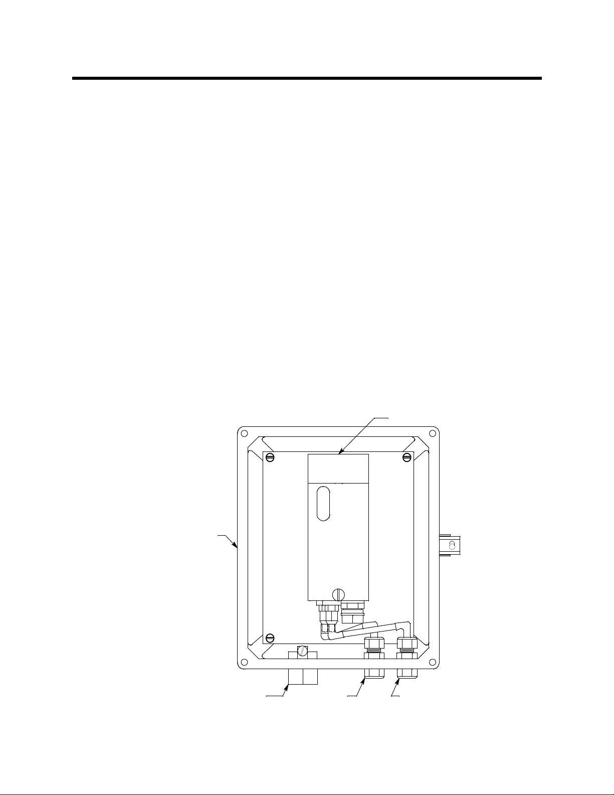
Enclosure
The enclosure is a type NEMA 4X plastic enclosure designed for use in areas that are
subject to rain or hosing down. A mounting foot is installed in each corner. Two sample
fittings are mounted on the bottom right of the enclosure and two 3/4” conduit hubs are
mounted to the left of the sample fittings.
Sample Fittings
The inlet fitting is on the bottom right of the enclosure and the exhaust fitting is to the left
of the inlet fitting. The fittings accept 1/4”O.D. x 1/8” I.D. Teflon tubing. The inlet fitting
has a short factory installed tubing stub for use with the hydrophobic filter.
Conduit Hubs
Two 3/4” conduit hubs are located to the left of the sample fittings. They are used for
routing wiring into the enclosure by using conduit or an appropriate cable bushing.
GD-K77D
NEMA4X Enclosure
(Cover not shown)
3/4" Conduit, 2X Exhaust
Figure 1: Component Location
Model GD-K77D4X-XX Sampl e Draw Transmi tter • 2
Sample Inlet
Page 6

Inlet Fitting Tubing Stub
A short tubing stub comes factory installed in the inlet fitting. It is used for connecting the
hydrophobic filter. If the hydrophobic filter is not used, or if you install the hydrophobic
filter in a different location, the tubing stub needs to be removed and replaced with
tubing. Do not pull the tubing stub downward to remove it. Instead, unscrew the lowe r
inlet fitting nut from the fitting body. The tubing stub should come out with the nut. Be
careful not to lose the O-ring that may come out with the tubing stub. Push the tubing
stub up and out of the inlet fitting nut being careful not to lose the ferrule set. Push the
new tubing up through the inlet fitting nut and replace the ferrule set and the O-ring, if it
came out, in the orientation shown in Figure 2. Screw the inlet fitting nut back onto the
fitting body and push the tubing upward until it stops. See Figure 2 for the inlet fitting
layout.
1/4" T ef l on Tube
Installation
O-ring
Fitting Body
Back Fer rul e
Nut
Front Ferrule
1/4" T ef lon Tube
Figure 2: Inlet Fitting with Tubing Stub
GD-K77D
The GD-K77D sample draw detector head is mounted to a plate inside the enclosure. The
GD-K77D sample fittings are factory connected to the sample fittings on the N EMA 4X
enclosure. See the GD-K77D operator’s manual for a complete description of the
GD-K77D.
This section describes how to install the GD-K77D4X-XX at the monitoring site.
Mounting the GD-K77D4X-XX
1. Select a mounting site that is representative of the monitoring environment. Consider
the following when you select the mounting site.
3 • Model GD-K77D4X-XX Sa mple Draw Transmitter
Page 7
• Select a site that is easily accessible for servicing.
• Select a site where the GD-K77D4X-XX is not likely to be bumped or disturbed.
Make sure there is sufficient room to make wiring and sample line connections at
the bottom of the GD-K77D4X-XX. Also make sure there is sufficient room to
perform start-up, maintenance, and calibration procedures.
• Select a site near the sampling area. The GD-K77D4X-XX is designed to detect a
variety of toxic gases, many of which a re easily absorbed in sample tubing. Keep
the sample line length to a minimum. Teflon PTFE tubing is recommended to
minimize samp l e absorption.
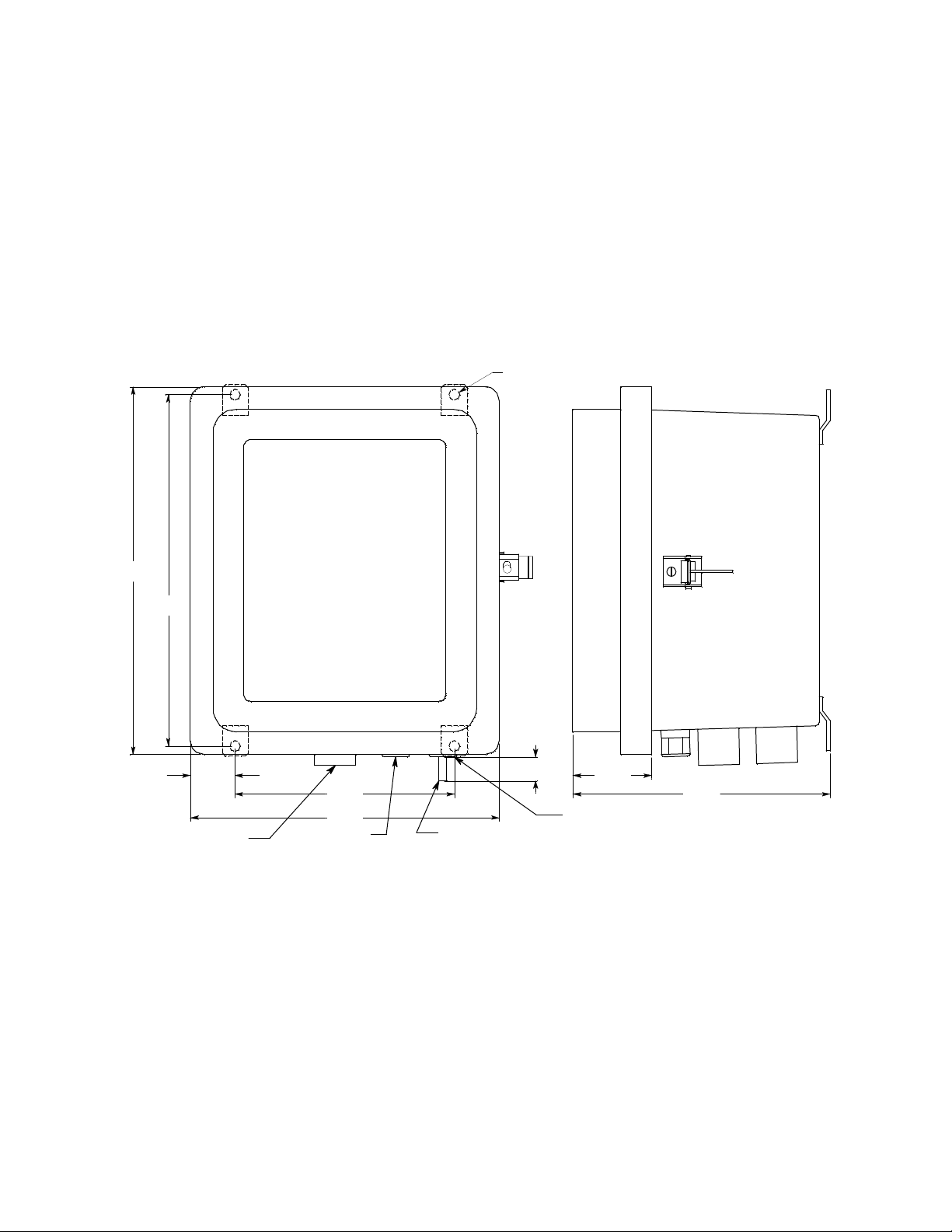
• Use four 1/4” screws through the mounting feet to mount the GD-K77D4X-XX to
a vertical surface. See Figure 3 for the mounting dimensions.
Ø .34, 4X
11.75
11.23
1.43
3/4" Conduit Hub, 2X
7.01
9.88
Exhaus t Fitting
0.85 MAX
Tubing Stub
2.51
8.22
In le t Fi tt i ng
Figure 3: Outline & Mounting Dimensions
Connecting Sample Lines to the GD-K77D4X-XX
1. Connect the hydrophobic filter to the tubing stub on the inlet by pushing the g ray
flexible tubing on the filter onto the stub.
If the hydrophobic filter is not used, or if you install the hy drophobic filter in a
different location, replace the tubing stub with 1/4’’ x 1/8’’ tubing as described in
“Inlet Fitting Tubing Stub” on page 3.
2. Connect a length of sample tubing to the other side of the hydrophobic filter and route
it to the sampling area. If the hydrophobic filter is not used, or if you install the
hydrophobic filter in a different loc at ion, route tubing from the inlet fitting to the
Model GD-K77D4X-XX Sampl e Draw Transmi tter • 4
Page 8

sample area. Be sure to keep the length to a minimum. Consult RKI Instruments, Inc.
for lengths of more than 20 feet.
CAUTION: Avoid loops or slumps in the incoming sample line. T o r educe response time, keep the
incoming sample line as short as possibl e.
3. Install 1/4’’ O.D. x 1/8” I.D. Teflon PTFE sample tubing to the gas out fitting. Route
the opposite end of the tubing to an open area where the sample can safely disperse or
to an exhaust duct.
Wiring the GD-K77D to a Controller
WARNING: Always verify that power to the GD-K77D4X-XX and to the controller are
off and that the controller’s and GD-K77D’s power switches are in the off
position before making wiring connections or adjustments.
1. Turn off power to the controller.
2. Place the controller’s and GD-K77D’s power switches in the OFF pos ition.
3. Use the conduit hubs at the bottom of the GD-K77D4X-XX for routing power and
signal cables into the enclosure. Route any relay wiring through one conduit hub, and
a 3-conductor shielded cable, or three wires in conduit, for controller connections
through the other conduit hub to minimize crosstalk.
GD-K77D Terminal Strip
Not
Used
NO
ALM2ALM1
NO
TR
NO
- (DC Grou n d)
+ 24 VDC
4 - 20 mA In (FB)
Controller
4. If shielded cable is used for controller wiring, connect the cable shield’s drain wire to
a chassis ground at the controller, but do not connect it at the GD-K77D4X-XX.
5 76 121110931 2
4
Cable Shield
ALARM
DEVICE
Figure 4: External Wiring
8
ALARM
DEVICE
ALARM
DEVICE
5 • Model GD-K77D4X-XX Sa mple Draw Transmitter
Page 9

Start Up
Operation
CAUTION: Leave the cable shield’s drain wire insulated and disconnected at the
GD-K77D4X-XX. You will connect the opposite end of the cable shield’s drain wire
at the controller.
CAUTION: At the controller, do not route power and GD-K77D wiring through the s a me
conduit hub. The power cable may disrupt the transmission of the GD-K77D’s
signal to the controller.
1. Turn on power to the controller.
2. Turn on the controller.
3. Turn on the GD-K77D. See the GD-K77D Operator’s Manual for GD-K77D startup
instructions.
See the GD-K77D Operator ’s Manual for an operational description of the GD-K77D that
is mounted inside the enclosure.
Maintenance/Calibration
See the GD-K77D Operator’s Manual for main tenance and calibration instructions. Use
the inlet fitting on the NEMA 4X enclosure to apply gas instead of the fittings inside the
enclosure on the GD-K77D.
Parts List
Table 4 lists replacement parts and accessories for the GD-K77D4X-XX.
Part Number Description
06-1273RK 1/4” O.D. x 1/8” I.D. Teflon PTFE tubing
17-4820RK Sample fitting, 1/4” tube bulkhead union
18-0107RK 3/4” conduit hub
33-0165RK-01 Hydrophobic filter w/flexible tubing stubs
Table 2: Parts List
Model GD-K77D4X-XX Sampl e Draw Transmi tter • 6
 Loading...