

Page 1

Model GD-K77D
Operator’s Manual
Part Number: 71-0046RK
Revision: B
Released: 3/1/11
www.rkiinstruments.com
Page 2

WARNING
Read and understand this instruction manual before operating
detector . Improper use of the dete ctor could result in bodily harm
or death.
Periodic calibration and maintenance of the detector is essential
for proper operation and correct readings. Please calibrate and
maintain this detector regularly! Frequency of calibration
depends upon the type of use you have and the sensor types.
T ypical calibration frequencies for most applications a re between
3 and 6 months, but can be required more often or less often
based on your usage.
Model GD-K77D
Operator’s Manual
Page 3

Warranty
RKI Instruments, Inc. warrants gas alarm equipment sold by us to be free from defects in
materials and workmanship, and performance for a period of one year from date of
shipment from RKI Instruments, Inc. Any parts found defective within that period will be
repaired or replaced, at our option, free of charge. This warranty does not apply to those
items which by their nature are subject to deterioration or consumption in normal service,
and which must be cleaned, repaired, or replaced on a routine basis. Examples of such
items are:
Absorbent cartridges Batteries
Pump diaphragms and valves Filter elements
Fuses
Warranty is voided by abuse including mechanical damage, alteration, rough handling, or
repairs procedures not in accordance with the instruction manual. This warranty indicates
the full extent of our liability , and we are not responsible for removal or replacement costs,
local repair costs, transportation costs, or contingent expenses incurred without our prior
approval.
THIS WARRANTY IS EXPRESSLY IN LIEU OF ANY AND ALL OTHER WARRANTIES
AND REPRESENTATIONS, EXPRESSED OR IMPLIED, AND ALL OTHER OBLIGATIONS
OR LIABILITIES ON THE PART OF RKI INSTRUMENTS, INC. INCLUDING BUT NOT
LIMITED TO THE WARRANTY OF MERCHANTABILITY OR FITNESS FOR A
PARTICULAR PURPOSE. IN NO EVENT SHALL RKI INSTRUMENTS, INC. BE LIABLE
FOR INDIRECT, INCIDENTAL, OR CONSEQUENTIAL LOSS OR DAMAGE OF ANY KIND
CONNECTED WITH THE USE OF ITS PRODUCTS OR FAILURE OF ITS PRODUCTS TO
FUNCTION OR OPERATE PROPERLY.
This warranty covers instruments and parts sold to users only by authorized distributors,
dealers, and representatives as appointed by RKI Instruments, Inc.
We do not assume indemnification for any accident or damage caused by the operation of
this gas monitor and our warranty is limited to replacement of parts or our complete goods.
Model GD-K77D
Operator’s Manual
Page 4

Table of Contents
Overview. . . . . . . . . . . . . . . . . . . . . . . . . . . . . . . . . . . . . . . . . . . . . . . . . . . . . . . . . . . . . . . . . . . . . . . . . . .1
About this Manual. . . . . . . . . . . . . . . . . . . . . . . . . . . . . . . . . . . . . . . . . . . . . . . . . . . . . . . . . . . . . . 1
Important Safety Precautions . . . . . . . . . . . . . . . . . . . . . . . . . . . . . . . . . . . . . . . . . . . . . . . . . . . . . 1
Specifications. . . . . . . . . . . . . . . . . . . . . . . . . . . . . . . . . . . . . . . . . . . . . . . . . . . . . . . . . 3
Description. . . . . . . . . . . . . . . . . . . . . . . . . . . . . . . . . . . . . . . . . . . . . . . . . . . . . . . . . . .4
Case. . . . . . . . . . . . . . . . . . . . . . . . . . . . . . . . . . . . . . . . . . . . . . . . . . . . . . . . . . . . . . . . . . . . . . . . 6
Alarm Lights . . . . . . . . . . . . . . . . . . . . . . . . . . . . . . . . . . . . . . . . . . . . . . . . . . . . . . . . . . . . . . . . . . 6
Display . . . . . . . . . . . . . . . . . . . . . . . . . . . . . . . . . . . . . . . . . . . . . . . . . . . . . . . . . . . . . . . . . . . . . . 6
Flowmeter. . . . . . . . . . . . . . . . . . . . . . . . . . . . . . . . . . . . . . . . . . . . . . . . . . . . . . . . . . . . . . . . . . . . 6
Internal and Back Panel Components . . . . . . . . . . . . . . . . . . . . . . . . . . . . . . . . . . . . . . . . . . . . . . 7
Block Diagrams . . . . . . . . . . . . . . . . . . . . . . . . . . . . . . . . . . . . . . . . . . . . . . . . . . . . . . . . . . . . . . . 8
Important Safety Procedures . . . . . . . . . . . . . . . . . . . . . . . . . . . . . . . . . . . . . . . . . . . . 9
Installation . . . . . . . . . . . . . . . . . . . . . . . . . . . . . . . . . . . . . . . . . . . . . . . . . . . . . . . . . .10
Precautions. . . . . . . . . . . . . . . . . . . . . . . . . . . . . . . . . . . . . . . . . . . . . . . . . . . . . . . . . . . . . . . . . . 10
Wall Mounting the Model GD-K77D . . . . . . . . . . . . . . . . . . . . . . . . . . . . . . . . . . . . . . . . . . . . . . . 11
Removing the Model GD-K77D . . . . . . . . . . . . . . . . . . . . . . . . . . . . . . . . . . . . . . . . . . . . . . . . . . 12
Electrical Connections . . . . . . . . . . . . . . . . . . . . . . . . . . . . . . . . . . . . . . . . . . . . . . . . . . . . . . . . . 12
Tubing Connections . . . . . . . . . . . . . . . . . . . . . . . . . . . . . . . . . . . . . . . . . . . . . . . . . . . . . . . . . . . 18
Tubing Material. . . . . . . . . . . . . . . . . . . . . . . . . . . . . . . . . . . . . . . . . . . . . . . . . . . . . . . . . . . . . . . 18
Operation . . . . . . . . . . . . . . . . . . . . . . . . . . . . . . . . . . . . . . . . . . . . . . . . . . . . . . . . . . . 19
Start-up Preparations . . . . . . . . . . . . . . . . . . . . . . . . . . . . . . . . . . . . . . . . . . . . . . . . . . . . . . . . . . 19
Basic Operation Flow and Operating Modes . . . . . . . . . . . . . . . . . . . . . . . . . . . . . . . . . . . . . . . . 19
Start Up. . . . . . . . . . . . . . . . . . . . . . . . . . . . . . . . . . . . . . . . . . . . . . . . . . . . . . . . . . . . . . . . . . . . . 20
Detection Mode . . . . . . . . . . . . . . . . . . . . . . . . . . . . . . . . . . . . . . . . . . . . . . . . . . . . . . . . . . . . . . 20
Maintenance Mode. . . . . . . . . . . . . . . . . . . . . . . . . . . . . . . . . . . . . . . . . . . . . . . . . . . . . . . . . . . . 23
Alarm Test Mode. . . . . . . . . . . . . . . . . . . . . . . . . . . . . . . . . . . . . . . . . . . . . . . . . . . . . . . . . . . . . . 28
Turning Off the Model GD-K77D . . . . . . . . . . . . . . . . . . . . . . . . . . . . . . . . . . . . . . . . . . . . . . . . . 28
Alarms. . . . . . . . . . . . . . . . . . . . . . . . . . . . . . . . . . . . . . . . . . . . . . . . . . . . . . . . . . . . . .29
Alarm Types . . . . . . . . . . . . . . . . . . . . . . . . . . . . . . . . . . . . . . . . . . . . . . . . . . . . . . . . . . . . . . . . . 29
Responding to Alarms . . . . . . . . . . . . . . . . . . . . . . . . . . . . . . . . . . . . . . . . . . . . . . . . . . . . . . . . . 30
Maintenance. . . . . . . . . . . . . . . . . . . . . . . . . . . . . . . . . . . . . . . . . . . . . . . . . . . . . . . . . 31
Monthly Maintenance . . . . . . . . . . . . . . . . . . . . . . . . . . . . . . . . . . . . . . . . . . . . . . . . . . . . . . . . . . 31
Semiannual Maintenance. . . . . . . . . . . . . . . . . . . . . . . . . . . . . . . . . . . . . . . . . . . . . . . . . . . . . . . 31
Calibration . . . . . . . . . . . . . . . . . . . . . . . . . . . . . . . . . . . . . . . . . . . . . . . . . . . . . . . . . . . . . . . . . . 32
Storage. . . . . . . . . . . . . . . . . . . . . . . . . . . . . . . . . . . . . . . . . . . . . . . . . . . . . . . . . . . . . . . . . . . . . 35
Replacing Components . . . . . . . . . . . . . . . . . . . . . . . . . . . . . . . . . . . . . . . . . . . . . . . . . . . . . . . . 36
Model GD-K77D
Operator’s Manual
Page 5

Troublesho oting. . . . . . . . . . . . . . . . . . . . . . . . . . . . . . . . . . . . . . . . . . . . . . . . . . . . . . 37
Trouble Alarm: Flickering PW/TR Lamp . . . . . . . . . . . . . . . . . . . . . . . . . . . . . . . . . . . . . . . . . . . . 37
PW/TR Lamp Off . . . . . . . . . . . . . . . . . . . . . . . . . . . . . . . . . . . . . . . . . . . . . . . . . . . . . . . . . . . . . 38
Abnormal Performance. . . . . . . . . . . . . . . . . . . . . . . . . . . . . . . . . . . . . . . . . . . . . . . . . . . . . . . . . 38
Unable to Calibrate. . . . . . . . . . . . . . . . . . . . . . . . . . . . . . . . . . . . . . . . . . . . . . . . . . . . . . . . . . . . 38
Slow Response. . . . . . . . . . . . . . . . . . . . . . . . . . . . . . . . . . . . . . . . . . . . . . . . . . . . . . . . . . . . . . . 38
Disconnected Fuse. . . . . . . . . . . . . . . . . . . . . . . . . . . . . . . . . . . . . . . . . . . . . . . . . . . . . . . . . . . . 39
Parts List. . . . . . . . . . . . . . . . . . . . . . . . . . . . . . . . . . . . . . . . . . . . . . . . . . . . . . . . . . . .39
Model GD-K77D
Operator’s Manual
Page 6

Overview
The Model GD-K77D has been specially developed for semiconductor gas-leak
monitoring and is one of the most advanced units of its kind. It contains a long-life pump
and electrochemical sensor to detect a wide variety of semiconductor gasses quickly and
reliably. The long-life sensor has a memory so it can be calibrated separately from the
monitor, then installed for quick and easy servicing. The Model GD-K77D’s narrow
footprint and wall mounting bracket permit flexible placement. Built for reliability and ease
of use, the Model GD-K77D includes the latest innovations in gas-leak monitoring
technology:
• Digital LED display for readout of gas concentrations
• Sensor information and calibration stored within sensor memory
• Several transmission options available
• Self-diagnostic functions performed by microcomputer
• Easy replacement of pump and sensor
• Two alarm levels plus trouble alarm
WARNING: The Model GD-K77D detects semiconductor gasses that may be toxic
or combustible. Users of the Model GD-K77D must follow the
instructions and warnings in this manual to assure proper and safe
operation of the Model GD-K77D.
About this Manual
This manual is intended for use with the RKI Instruments® Intelligent Gas Detector, Model
GD-K77D. It describes the Model GD-K77D’s specifications, internal components,
operation, calibration, and maintenance.
Important Safety Precautions
To ensure the consistent performance and reliability of the RKI Instruments Intelligent Gas
Detector, Model GD-K77D, carefully read and follow the instructions in this manual before
using the unit. Keep this manual where you can find it easily. When operating or
performing maintenance on the Model GD-K77D, refer back to this manual as required.
Also keep maintenance records, and use them to plan for future repairs and maintenance
of the Model GD-K77D.
If the Model GD-K77D is not operated according to the instructions in this manual, RKI
Instruments, Inc. cannot assume any responsibility for consequential injury or damage.
Because the Model GD-K77D is considered to be safety equipment designed to detect
semiconductor gases, which can be toxic or explosive, be sure to check the Model GDK77D daily. If any problem or malfunction is found, contact your local distributor, or RKI
Instruments, Inc. immediately.
Throughout this manual you will see cautionary labels. Read them carefully and heed their
warnings. Failure to do so may result in injury or damage.
1 • Overview Model GD-K77D Operator’s Manual
Page 7

DANGER: This label alerts you to the possibility of serious injury or death when
using or servicing the Model GD-K77D improperly in potentially
hazardous environments or conditions. The Model GD-K77D is not
explosion proof. Do not use the Model GD-K77D for gas detection
above the lower explosive limit (LEL).
WARNING: This label alerts you to the potential danger of electrical shock, or
other hazards. When electrical safety is n ot followed, injury or damage
to the Model GD-K77D may result. Remember that the Model GD-K77D
is an electrically powered device. In some circumstances, the Model
GD-K77D may be affected by electrical noise, static electricity, or
electromagnetic interference. If the environment in which the Model
GD-K77D is to be placed has these electrical hazards, take the
appropriate steps to shield the Model GD-K77D properly.
CAUTION: This label alerts you to the possibility of injury or damage to the Model GD-K77D
when operation and maintenance of the Model GD-K77D are not performed in
accordance with the instructions in this manual. When replacing parts for the Model
GD-K77D, use only RKI replacement parts. Modified or non-RKI replacement parts
can damage the Model GD-K77D. Should such damage occur, RKI Instruments, Inc.
is not responsible, and the warranty may be voided.
NOTE: This label indicates that important advice or operating or maintenance tips follow. Read
the note carefully and follow its instructions.
Model GD-K77D
Operator’s Manual Overview • 2
Page 8
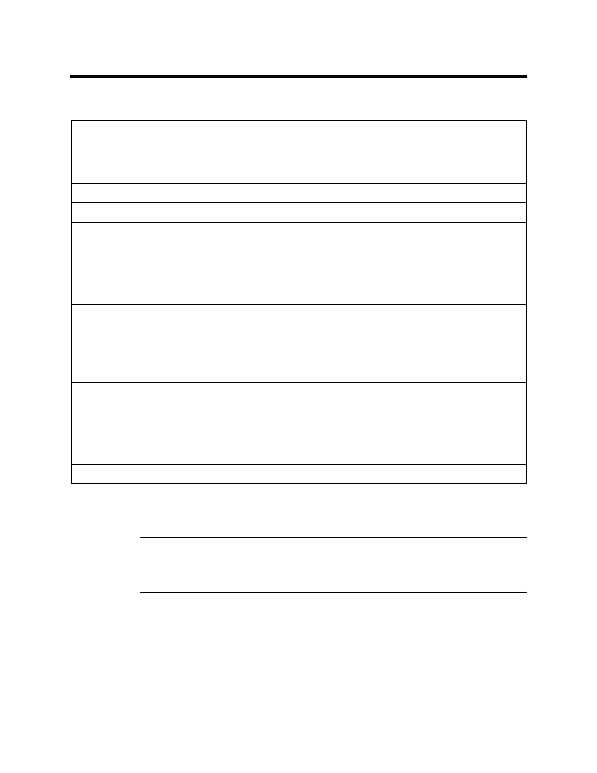
Specifications
Table 1: Specifications for the Model KD-K77D
Model GD-K77D GD-K77D-NT
Relay output for remote alarm Electrochemical cell
Relay output for remote alarm Refer to the RKI Instrument, Inc. list of detectable gasses
Target gas and detection range See RKI List of Detectable Gases
Accuracy ± 10% of reading or ± 5% of full scale (whichever is greater)
Signal output (4-20 mA) Two-wire digital signal
Display Digital LED display, 4 digit
Alarms Two alarm levels: alarm 1 (yellow LED),
alarm 2 (red LED), trouble
Relay output for remote alarm Dry contact for each alarm1, alarm2, and trouble alarm
Self-diagnostic functions Trouble, low flow, system failure, communication error
Temperature and humidity ranges 0-40 C, 30-85% relative humidity
Power requirements 24 VDC+/- 10%, approximately 10W
Recommended cable (see also RKI
wiring chart)
Dimensions and weight 2.8"(W) x 6.7"(H) x 6.0"(D), 4.4lb.
Recommended tubing 4 mm x 6 mm PTFE (Teflon tubing, RKI part # 06-1272RK)
Fuse 5.2 mm diameter x 20 mm length; 2A, 250V
Specifications subject to change without notice.
Accessories: Dust filter
WARNING: When using the GD-K77D, you must follow the instructions and warnings
in this manual to assure proper and safe operation of the GD- K77D and to
minimize the risk of personal injury. Be sure to maintain and period ically
calibrate the GD-K77D as described in this manual.
18 gage shielded cable Shielded twisted pair cable (18
gage)
3 • Specifications Model GD-K77D Operator’s Manual
Page 9
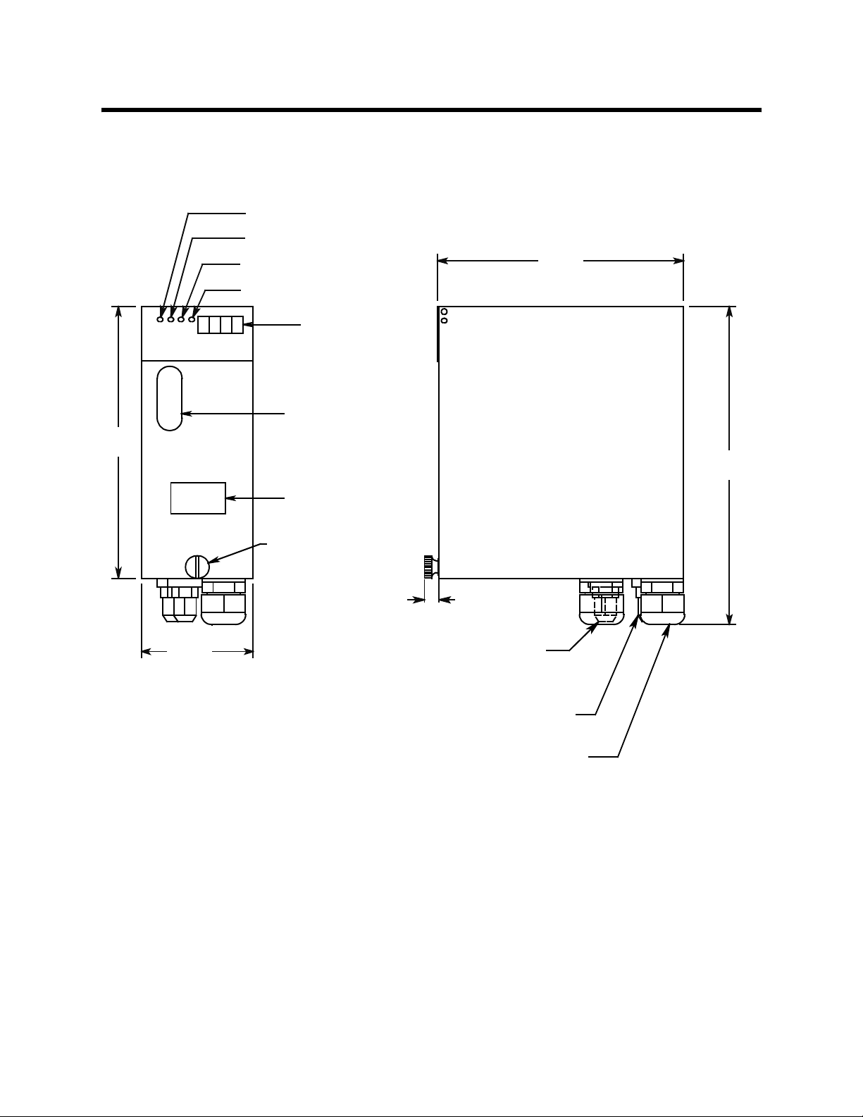
Description
PW/TR LED
6
X
.70
The Model GD-K77D is designed to measure gas leaks in an industrial setting. Gas leaks
are detected by an internal electrochemical sensor, and the gas concentration is displayed
by a four-digit LED display.
ALM1 LED
ALM2 LED
6.05
SKIP LED
LED Display
Flow Meter
Window
8.0 MA
ID Card
Holder
GAS DETECTOR
MODEL
GD-K77D
Cover
Retaining
Screw
.36
2.80
Gas Inlet, fo r ø 4 x 6
mm PTFE Tube
Gas Exhaust, for ø 4 x 6
mm PFTE Tube
Cable Bushing
Figure 1: External Component Location
Model GD-K77D
Operator’s Manual Description • 4
Page 10
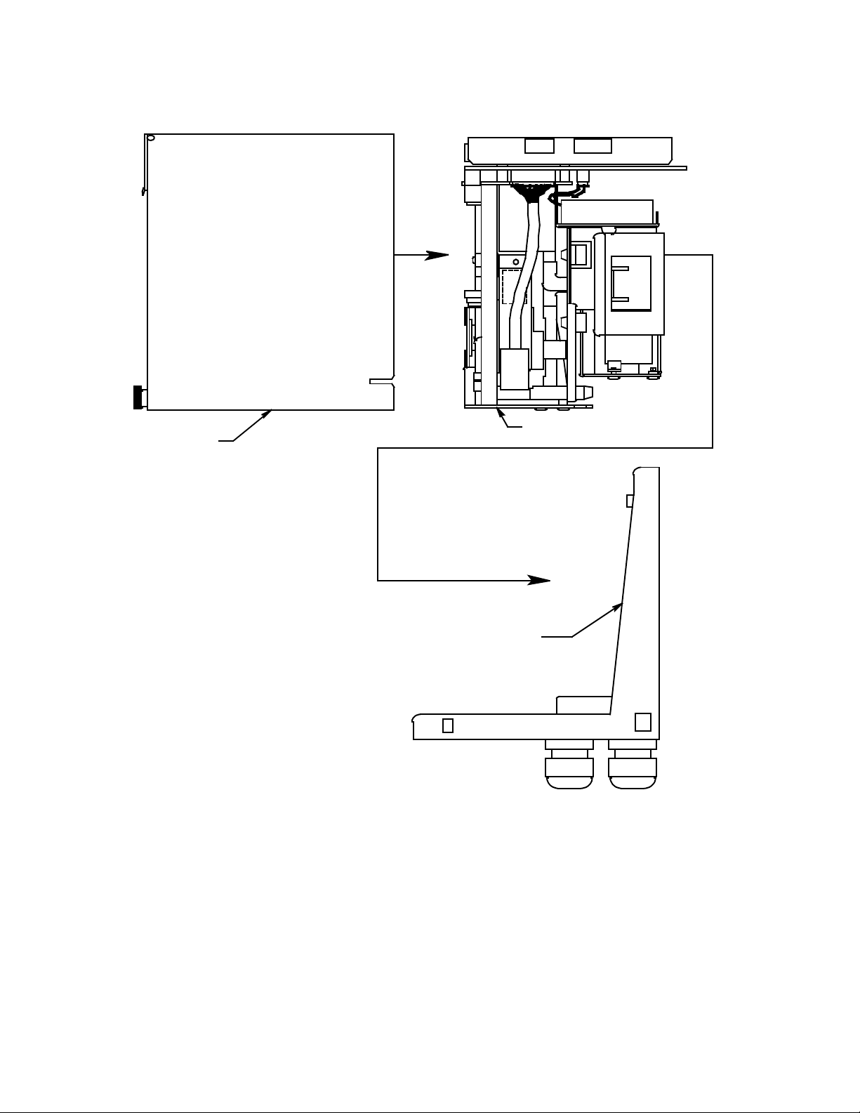
Cover
Detector unit
Wall mounting bracket
Figure 2: Removing the Cover and Detector Unit
5 • Description Model GD-K77D Operator’s Manual
Page 11

The Model GD-K77D provides a three-wire 4-20mA signal output for a controller. The
Model GD-K77D-NT provides a two-wire digital signal which is used by the RM-77NT
accessory and is then converted to either an RS-232C or RS-485 signal. It has two gas
alarm levels, two sets of gas alarm relay contacts, a trouble alarm, and trouble relay
contacts.
The Model GD-K77D is a sample draw gas detection head. The Model GD-K77D draws in
the sample gas from a remote location using an internal pump. The flow system directs
the gas to an internal gas sensor. Various lengths of inlet tubing can be used, and tubing
length is determined by the target gas and the operating environment. When using the
Model GD-K77D in areas containing dust or other particulate contamination, use the
appropriate sample filter. The correct sample filter is dependent on the target gas.
Case
The Model GD-K77D has a rugged metal case. A sturdy wall mounting bracket is supplied
that allows the Model GD-K77D to be securely attached to a wall for convenient operation
and maintenance.
On the fron t of th e ca se ar e f o u r LE D s, a LE D di sp l ay, a flowme te r, and a large s cr e w t h at
is used to open and close the case cover. On the bottom are located a gas inlet, a gas
exhaust, and two cable bushings for external wiring.
Alarm Lights
Four light-emitting diodes (LEDs) provide visual alarms for gas concentrations and
malfunctions, and are part of the detector panel along with the LED display. These LEDs
are located on the front of the unit in the upper left corner for greatest visibility. They
perform the following functions:
PW/TR. Indicates power on or off and warns that the Model GD-K77D is not operating
normally. When PW/TR is lit (green color), the Model GD-K77D is fully powered and is
operating normally. When the PW/TR is off, power to the Model GD-K77D has been shut
off. When the PW/TR is flickering, the Model GD-K77D is not operating normally.
• ALM1. Indicates the first gas alarm (orange color).
• ALM2. Indicates the second gas alarm (red color).
• SKIP. Indicates that the Model GD-K77D is in Maintenance Mode and has temporarily
stopped gas detection.
Display
An LED display shows gas concentration in parts per million (PPM). The LED display is
located on the front of the unit in the upper right corner for easy viewing.
Flowmeter
The flowmeter checks the sample flow rate of the target gas reaching the sensor inside
the Model GD-K77D. The flowmeter is a glass tube on which are marked two red flow
lines. A flow ball indicates whether the flow rate is within, or outside, the red flow lines.
Model GD-K77D
During normal operation, the standard flow rate to the sensor is approximately 0.5 L/min,
and the flow ball should be within the two red flow lines. When the ball drops below the
bottom flow line, the Model GD-K77D cannot accurately detect the target gas. Increase
the flow rate. When the ball rises above the top flow line, reduce the flow rate. For more
information about adjusting the gas flow rate, see “Flow Adjustment Up/Down” under
“Internal and Back Panel Components.”
Operator’s Manual Description • 6
Page 12
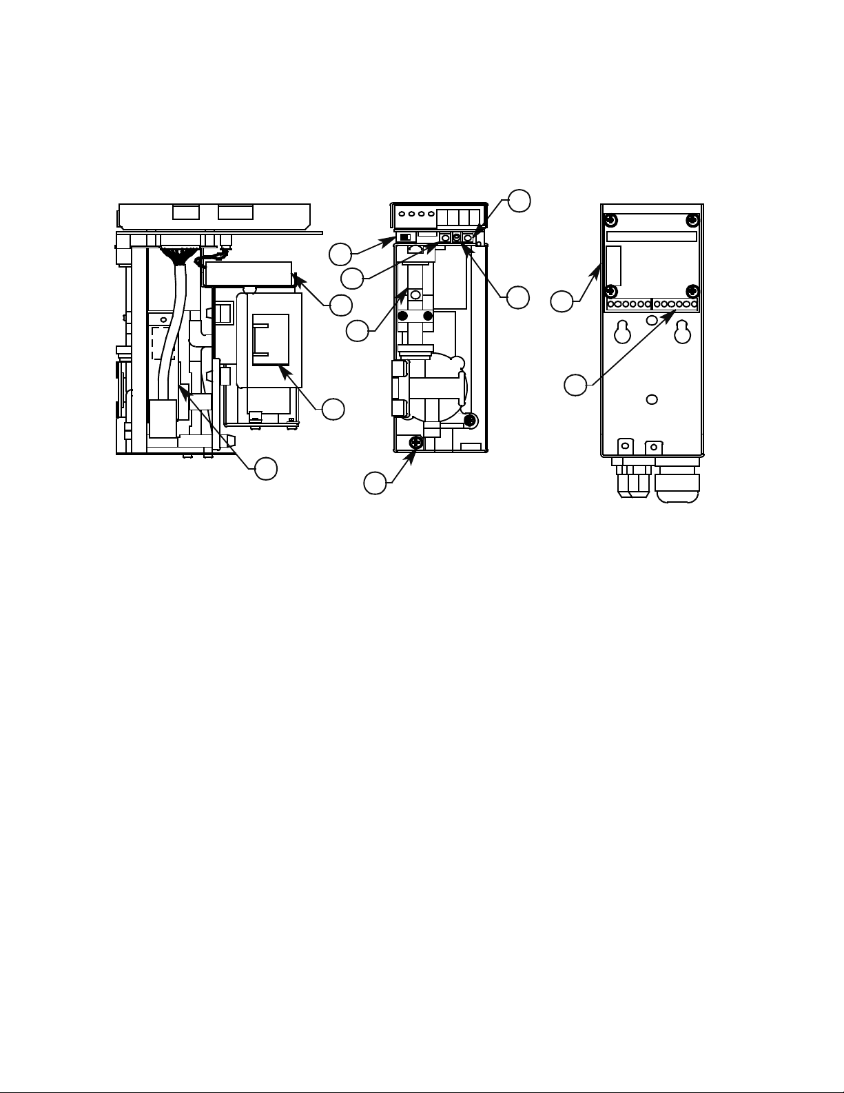
Internal and Back Panel Components
Refer to the diagram below for the location of Model GD-K77D internal and back panel
components, which are described below. After each component name is a number, which
corresponds to the same number in the diagram.
13
10
12
15
16
14
20
11
19
Detector Unit
Side View
Power Switch (10). Turns power on or off to the Model GD-K77D.
Power Fuse (11). Protects the Model GD-K77D from a power overload.
Mode Switch (12). T oggles the Model GD-K77D’s operating mode between detection and
maintenance. When the Model GD-K77D is being used for gas detection, the Model GDK77D is in normal operation; when performing maintenance on the Model GD-K77D, use
this switch to put the unit into Maintenance Mode.
T est/Set Switch (13). This switch has several functions in Maintenance Mode.
FLOW ADJ Switch (
GD-K77D when the unit is in normal operation. Gas flow adjustments are made when the
flow ball is outside the red flow lines. When the flow ball is above the top flow line, press
the FLOW ADJ switch down to reduce the flow rate. When the flow ball is below the
bottom flow line, press the FLOW ADJ switch up to increase the flow rate. This switch is
also used to increase or decrease parameters in Maintenance Mode.
17
18
Detector Unit
Front View
Wall Mounting
Bracket
Front View
Figure 3: Internal Componen ts
▲/▼) (14). Increases or decreases the gas flow rate to the Model
Pump (15). Draws the sample gas by suction to the sensor inside the Model GD-K77D.
Lithium Battery (16). Provides a bias voltage to the Model GD-K77D sensor in the event
of a power outage or a drop in line voltage.
7 • Description Model GD-K77D Operator’s Manual
Page 13
CAUTION: When the Model GD-K77D is not used for long periods of time, the lithium battery may lose
power. The lithium battery, under normal operating conditions, has a life expectancy of about
three (3) years from the date of manufacturing. When the lithium battery is replaced, put the unit
into maintenance mode before replacing the battery by pressing the Mode switch for 3 seconds.
Then calibrate the unit as described in the Calibration section. If the Model GD-K77D has been
stored for a long time, calibrate the Model GD-K77D when the unit is put back into service.
Sensor (17). Detects the target gas.
Detector Unit Set Screw (18). Tighten this screw when attaching the wall mounting
bracket to the Model GD-K77D’s case.
Terminals (19). Provides terminations for external wiring.
Flowmeter (20). The flowmeter indicates whether the sample flow rate of the sample
reaching the sensor inside the Model GD-K77D is okay. See “Flowmeter” for more
information.
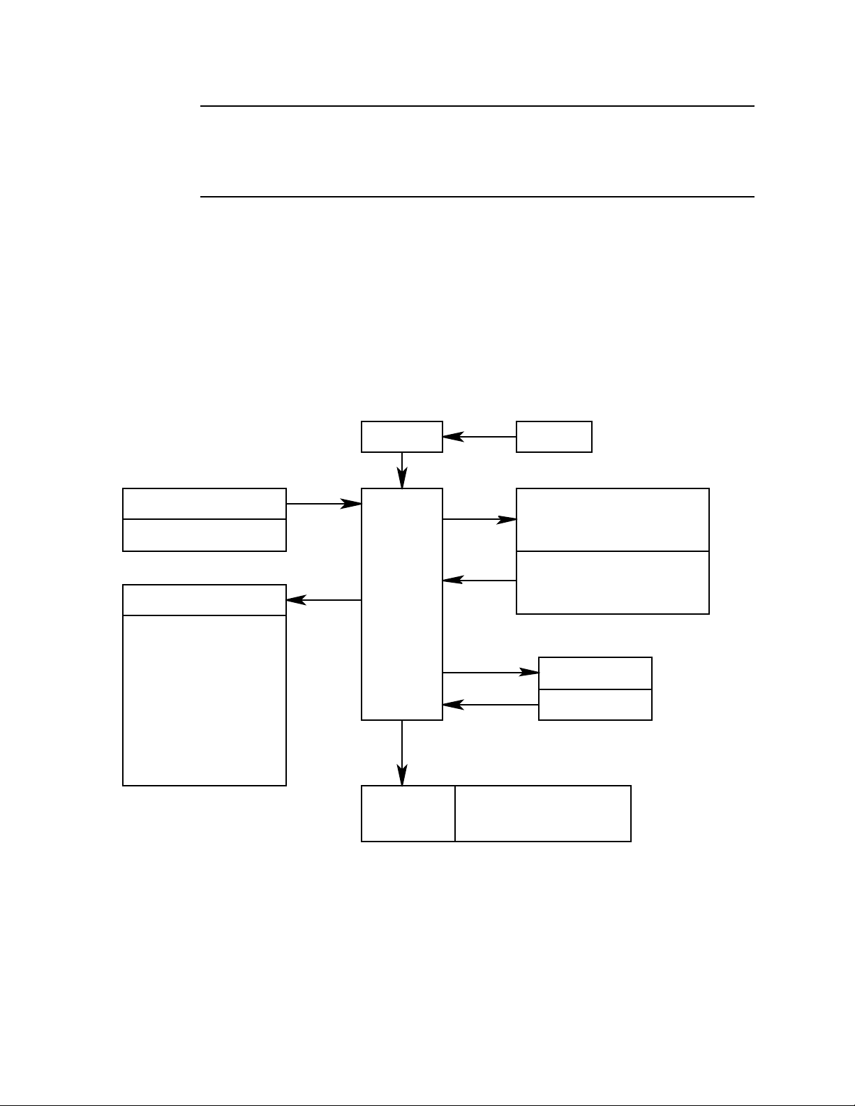
Block Diagrams
Amp unit Sensor
Power sourc e
Display
POWER INPUT(24 VDC)
Al a r m co n tact contro l
Gas alarm contact
(ALM 1, ALM 2)
Tro ubl e alarm contact
(Trouble)
- Relays are normally
de-energized (N DE)
- Contac ts close at
alarm condition
Co ntrol unit
Transmission
GD-K77D 4-20 mA
Figure 4: Electrical Block Diagram
(PW /TR) (ALM 1) (ALM2 ) (SKIP)
Pump
(MODE) (FLOW ADJ.s t ) TEST/SET)
Pump
Low flow sensor
Trans mission
Model GD-K77D
Operator’s Manual Description • 8
Page 14
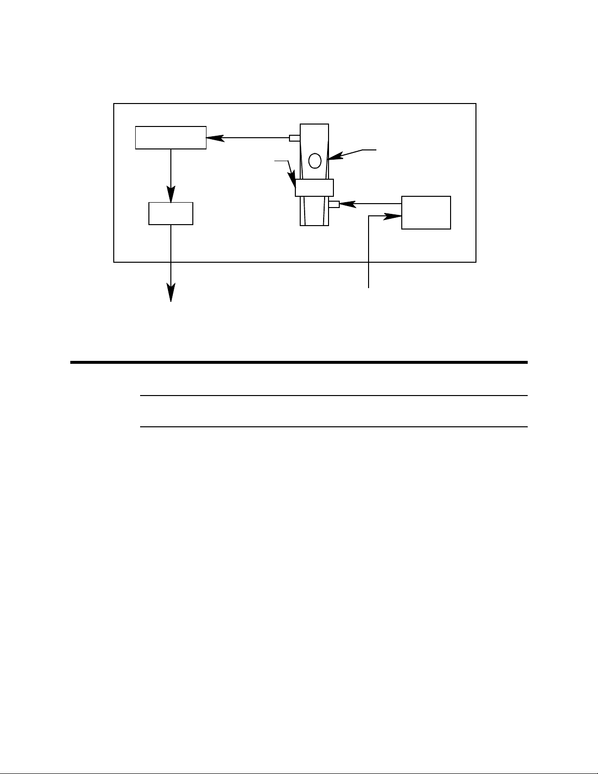
Baffle
Flowmeter
Low flow sensor
Pump
GAS OUT GAS IN
Figure 5: Flow Diagram
Important Safety Procedures
WARNING: Before installing and operating the Model GD-K77D, please read the
following list of precautions before continuing:
Power Source. Check the power source before turning on the Model GD-K77D. Make
sure the power source voltage is within the specified voltage range.
Ground Wire. Do not cut or remove the ground wire to the Model GD-K77D.
Fault Protection. When an electrical fault has occurred (e.g., the fuse blows), do not
attempt to operate the Model GD-K77D. Before starting up the Model GD-K77D, make
sure an electrical fault has not occurred.
Sens or
Fuse. When replacing the Model GD-K77D’s fuse, turn off the power to the unit. Use only
replacement fuses that have the correct current and voltage ratings. Do not use any fuse
other than the one specified for the Model GD-K77D. Using a non-specified fuse will
cause a short and damage the Model GD-K77D.
Explosive Gases. Do not operate the Model GD-K77D in environments containing
explosive gases. The Model GD-K77D is not explosion-proof; its internal circuitry may
cause a spark which could ignite combustible gas or vapors.
External Connections. After making sure the Model GD-K77D is properly grounded and
an electrical fault has not occurred, wire all external connections to the Model GD-K77D.
Lithium Battery. When the lithium battery is replaced, turn all power off to the Model GDK77D before removing the battery. Do not recharge, burn, mutilate, or expose the lithium
battery to temperatures greater the 212
not immerse the battery in water.
9 • Important Safety Procedures Model GD-K77D Operator’s Manual
o
F (100o C) because it may leak or explode. Do
Page 15

Sensor. Use caution when handling the sensor. The electrolyte contains a dilute acid that
can damage to clothing or other materials, and it can cause skin burns or blindness should
the acid come in contact with the eyes. If the electrolyte makes contact with the skin or
eyes, wash the affected area very thoroughly with water. With eye contact, seek medical
attention immediately.
High Gas Levels. Should the target gas reach levels greater than the alarm present level,
swift and appropriate action is crucial to avoid a potentially hazardous condition.
Communication Devices. Do not use portable telephones or two-way radios near the
Model GD-K77D. The electrical emissions or radio waves of such devices may affect the
Model GD-K77D’s readings.
Power On. When turning the power back on to the Model GD-K77D, wait 25 seconds
before taking readings; otherwise abnormal output may result.
Flowmeter. When the Model GD-K77D is drawing in the sample gas, make sure the flow
ball is between the top and bottom flow lines. When the ball drops below the bottom flow
line, the Model GD-K77D cannot accurately detect the target gas. Increase the flow rate.
Dust Filter. When sampling gas from a dusty environment, use the recommend filter to
avoid drawing dust into the Model GD-K77D. Place the external dust filter on the end of
the hose used to draw in the sample gas. When changing the dust filter, turn off the Model
GD-K77D.
Installation
Precautions
Professional installation of the Model GD-K77D by a licensed contractor is highly
recommend for the best and safest results. The following is a list of precautions that will
ensure the operating performance of the Model GD-K77D:
• Dusty Environments. When extracting gas from a dusty environment, the
recommend filter should be used to avoid drawing dust into the Model GD-K77D.
Place the external dust filter on the end of the hose used to draw in the sample gas.
When changing the dust filter, turn off the Model GD-K77D.
• Sun Light. Do not install the Model GD-K77D in direct sun light, which may affect the
operation and performance of the Model GD-K77D.
• Vibration. Do not install the Model GD-K77D in areas affected by shock and vibration,
which may damage the Model GD-K77D’s electronics.
• Electronic Emissions. Do not install the Model GD-K77D in areas with high levels of
radio interference or electronic noise. This electronic interference may cause
abnormal readings. And do not place the Model GD-K77D near electrical wiring or
other electrical devices, such as industrial motors.
• T arget Gas. Do not place the Model GD-K77D where the target gas is to be detected.
Use the sampling hose to place the Model GD-K77D at a safe distance from the gas
source.
Model GD-K77D
• Dangerous or Inconvenient Locations. The Model GD-K77D requires regular
maintenance. Do not place it in environments that are potentially hazardous (e.g.,
near high voltage cables), or in locations in which maintenance is very inconvenient
(e.g., near objects that prevent easy access to the controls inside the Model GDK77D).
Operator’s Manual Installation • 10
Page 16

• Grounding. Make sure to ground the Model GD-K77D properly during installation.
7
7
6.05
4
2.80
6
Wall Mounting the Model GD-K77D
CAUTION: When installing the wall mounting bracket, make sure to attach it securely to the wall.
If not securely attached, the Model GD-K77D may fall causing damage to the unit.
Find a suitable location for the Model GD-K77D. Allow enough room around the wall
mounting bracket for the Model GD-K77D to be mounted easily. See “Precautions” on the
previous page for installation warnings.
1. Attach the wall mounting bracket to the wall using #10 screws.
2. Mount the Model GD-K77D to the wall mounting bracket.
3. Fasten the screw on the front bottom of the Model GD-K77D.
Display
Area
1.5
1.9
1.5
.70
GAS DETECTOR
Flow Meter
Window
ID Card
Holder
MODEL
GD-K77D
8.0 MAX
.59
1.38
.36
TYPICAL MULTIPOINT
Gas Inlet, For ø 4 x 6
mm PTFE Tube
Gas Exhaust, for ø 4 x 6
mm Tube
Cable Bushing
3.15 Minimum
INSTALLATION
1.57
1.97
1.54
3 #10 screws recommended
for mounting
Figure 4: Outline & Mounting Dimensions
11 • Installation Model GD-K77D Operator’s Manual
Page 17

Removing the Model GD-K77D Detector Unit
When connecting tubing, making electrical connections, or servicing the Model GD-K77D,
it is more convenient to remove the Model GD-K77D detector unit from its wall mounting
bracket.
Loosen this
screw
Figure 5: Removing the Detector Unit
1. Loosen the large screw on the front of the unit and remove the cover.
2. Loosen the screw on the lower part of the unit.
3. Remove the Model GD-K77D detector unit from the wall mounting bracket.
NOTE: When returning the Model GD-K77D detector unit to the wall mounting bracket,
assemble the unit in reverse order.
Electrical Connections
CAUTION: Unstable power o r power wit h elect rical no ise ma y caus e the Mod el GD-K77 D to giv e
false readings or to trigger a false alarm. When connecting the Model GD-K77D to a
power source, carefully follow the instructions in this manual.
During warm up at power on and during a power failure, unwanted alarms may occur
depending on the relay logic and wiring used. Take any steps necessary to address this
situation.
Model GD-K77D
Operator’s Manual Installation • 12
Page 18

Power Requirements
Table 2: Power Requirements for the Model GD-K77D
Power Voltage DC-24V +/- 10% (Terminal Voltage)
Power Failure Tolerance (Time) Approximately 10 milliseconds. After a power failure
of 10 milliseconds, the Model GD-K77D re-starts.
To ensure continuous operation, install a standby battery.
Requirements Do not connect power to the Model GD-K77D con-
taining a high power load or with high frequency
noise.
If noise is present, use a line filter to separate the
power from the noise source.
When rack-mounting the Model GD-K77D in an area
with restricted ventilation, allow for adequate ventilation by mounting fans near the unit.
External Alarm
The Model GD-K77D can be used to control an external buzzer or alarm light. The Model
GD-K77D ‘s external alarm contacts are rated for 0.5 A @ 125 VAC, 1A @ 30 VDC, and
0.5 A @ 60 VDC. Use the alarm contacts on the Model GD-K77D to control only low
power devices. If heaver loads or inductive loads need to be controlled, use a slave relay
to accommodate the load. A CR circuit device (or Spark Killer) should be installed to
protect the alarm contacts if there is any question about the load. When driving a slave
relay, use a S park Killer since the slave relay is an inductive load.
Figure 4: CR circuit for Alarm Relay
13 • Installation Model GD-K77D Operator’s Manual
Page 19

WARNING: The alarm contacts on the Model GD-K77D are designed to take a
resistance load and not an inductive load. (An inductive load can be
created by a patlight, external relay, buzzer, siren, fan, fluorescent
light, motor, etc.)
When an inductive load is present, a very high reverse voltage may be
generated that can melt the alarm contacts on the Model GD-K77D,
damage the external alarm, or damage the CPU if one is connected to
the system. Also note that the intrusion of electrical noise in the alarm
circuit can cause the same problems generated by an inductive load.
To avoid these problems, whether created by an inductive load or by
noise, do not use an inductive load and protect the alarm contacts on
the Model GD-K77D with the appropriate surge protectors.
Grounding
Attach ground wires to the ground terminals on the Model GD-K77D, labeled chassis
(earth) ground bolts in the diagram below, before turning on the power to the Model GDK77D.
WARNING: Be sure to ground the Model GD-K77D properly for safe operation. Do
not connect the ground wires to the sample tubing.
Model GD-K77D
Operator’s Manual Installation • 14
Page 20

Chassis
Ground
Chassis
Ground
Figure 5: Grounding the GD-K77D
GA S IN
GA S OU T
15 • Installation Model GD-K77D Operator’s Manual
Page 21

Wiring
WARNING: When hooking up wires to the Model GD-K77D at the installation site,
be very careful not to damage the internal electronics of the Model
GD-K77D by a static electric discharge or by improper grounding.
Place the Model GD-K77D detector unit on its side. A vertical placement may cause the
unit to fall over, which may damage the unit.
For the power and signal cables, do not lay them out next to other power cables that carry
an electrical load.
4-20mA Specifications
3-wire 4-20mA
• 18-gauge wire, 3-wire shielded cable recommended.
• For most applications, see RKI wiring chart for more information.
D-K77D Terminal Strip
G
Factory Installed
Jumper
3
4
5
6
RM-570 Controller
w/EC-583 Module
Detector Terminals
Power
Source
Not
Used
21345
Alarm De vice
Figure 6: Wiring to RM-570 W/EC-583 Module
ALM1
NO
67
ALM2
NOTRNO
8 9101112
Power
Source
Alarm Device
Power
Source
Alarm Device
Model GD-K77D
Operator’s Manual Installation • 16
Page 22

GD-K77D Terminal Strip
- (DC Ground)
+24VDC
4-20mAIn(FB)
Controller or
Recording Device
Not
Used
Power
Source
5
31 2
4
Alarm Device
ALM2ALM1
NO
NO
76 121110
98
TR
NO
Power
Source
Alarm Device
Power
Source
Alarm Device
Figure 7: Wiring to a Generic Controller, Typical 3-wire
17 • Installation Model GD-K77D Operator’s Manual
Page 23

Tubing Connections
Tube Fittings
Two tube fittings are provided for sampling, one for inlet and one for exhaust. The fittings
accept 4 mm (ID) x 6 mm (OD) Teflon tubing.
Tubing
Insert
Ferrule
Nut
4 x 6 mm Teflon
PTFE Tubing
Figure 8: Inlet/Exhaust Fitting Use
Flow Rate
The flow rate of the Model GD-K77D is 0.5 L/M (liters per minute)
Tubing Material
The tubing materials you choose will depend upon the target gas being detected. Some
target gases are corrosive while others are absorptiv e. Choos e you r tubing mate rial s
carefully for both length and material. RKI Instruments recommends PTFE Teflon tubing.
Model GD-K77D
Operator’s Manual Installation • 18
Page 24

Operation
Start-up Preparations
To avoid the possibility of electrical shock or damage to the Model GD-K77D, follow the
precautions listed below before turning on the unit:
• Make sure the Model GD-K77D has been properly grounded.
• Check all wiring connections to external devices.
• Make sure the power voltage is within specification (DC-24V +/- 10%, Terminal
Voltage).
• Check the wiring connections to any external alarms.
• Make sure the correct dust filter has been properly installed.
CAUTION: Because dust filters are designed for specific target gases, it is very important to
check whether the correct dust filter has been installed on the Model GD-K77D.
• Check whether the Model GD-K77D’s fuse has the correct current and voltage.
Basic Operation Flow and Operating Modes
The diagram below shows the basic operation flow of the Model GD-K77D. There are
three basic operating modes:
• Detection Mode (Normal operation)
• Alarm Test Mode
• Maintenance Mode
Start-up preparation
Power on
Initial clear (about 25 seconds)
Detection mode
Test/set switch (press for about 3 seconds)
Alarm test mode
Mode, press for about 3 seconds
Maintenance Mode 1 & 2
Figure 9: Operation Flow Chart
19 • Operation Model GD-K77D Operator’s Manual
Page 25

The basic operation flow and the three operating modes are described in this section of
the manual.
Start Up
Power On
1. Before turning on the power to the Model GD-K77D, read “Start-up Preparations”
described above.
2. Remove the front cover of the Model GD-K77D if it is still attached to the Model GDK77D. See “Removing the Model GD-K77D Detector Unit” for more information.
3. The power switch is located on the front panel beneath the alarm lights and above the
flowmeter.
4. To turn the power on, move the switch to the right. To turn the power off, move the
switch to the left. After the power has been turned on, the PW/TR light turns on and
after several seconds the pump begins working. An initial warm up is performed for
approximately 25 seconds in which the Model GD-K77D’s system is checked. This
system check includes the external output, alarm, and trouble action, and shut-off
(lamp and contact).
Flowmeter Adjustment
1. Check the flowmeter to make sure the flow ball is between the two red flow lines.
2. If the flow ball is not between the red flow lines, adjust the air flow. When the flow ball
is above the top flow line, press the FLOW ADJ switch down to reduce the flow rate.
When the flow ball is below the bottom flow line, press the FLOW ADJ switch up to
increase the flow rate.
NOTE: The flow rate of the Model GD-K77D is 0.5 LPM. When the flow ball drops below the bottom flow line,
the Model GD-K77D cannot accurately detect the target gas. Increase the flow rate.
CAUTION: Allow the unit to warm-up for 2 hours before setting the zero reading.
Set the Zero Read i n g
See the Zero Adjustment section below for instructions on how to set the zero.
Detection Mode
Displays
The Model GD-K77D’s Detection Mode uses two types of indications:
• An LED (light emitting diode) display, which shows the gas concentration
• LED lamps show:
Model GD-K77D
• Power/Trouble (PW/TR)
• Alarm 1 (ALM1)
• Alarm 2 (ALM2)
• Skip (SKIP)
Operator’s Manual Operation • 20
Page 26

Operation Flow
The diagram below shows the operation flow for Detection Mode. In Detection Mode, the
PW/TR light is on and the LED display shows the concentration of the target gas.
LED lamp function
Start-up preparation
Power on
Initial warm-up (about 25 seconds)
Detection mode
Light off
PW/TR
PW/TR
Light on
LED indication
ALM1
ALM1
ALM2 SKIP
ALM2 SKIP
Flashing
Display indication
0.
00
Gas Alarm
During an alarm condition, ALM1 will be on if the gas concentration rises above the alarm
1 set point, and ALM2 will be on if the gas concentration rises above the alarm 2 set point.
The LED display will show the concentration of the target gas. The example below
illustrates an alarm 1 condition with a gas concentration of 0.5 ppm.
LED indication
PW/TR
21 • Operation Model GD-K77D Operator’s Manual
ALM1
ALM2 SKIP
Display indication
0.
0
5
Page 27

Zero Suppression
During Detection Mode, the display indicates “0” if the reading is below +6% of full scale.
PW/TR
LED indication
ALM1
ALM2 SKIP
Display indication
0.
0
0
During Detection Mode, the display shows readings above +6% of full scale.
PW/TR
LED indication
ALM1
ALM2 SKIP
Display indication
0.
6
0
“-0.00” displays when the reading falls below -10% of full scale.
PW/TR
LED indication
ALM1
ALM2 SKIP
Display indication
0.
0
0
WARNING: When the display shows a “-0.00,” adjust the zero reading as
described in the calibration section of this manual.
Trouble Conditions
The following table shows the possible trouble conditions that may occur:
Table 3: Trouble Conditions
Display Condition
E-00 System Fault
E-01 Sensor Disconnected
E-04 Zero Suppression Trouble
E-05 Low Flow Alarm
Model GD-K77D
Operator’s Manual Operation • 22
Page 28

4-20mA Output
The following graph illustrat e s the relat ion ship between the 4-20mA output and the gas
concentration.
External output
22mA
20mA
4 mA
2.5 mA
0
6% of full scale
zerosuppression
Full
Scale
Measuring mode
Maintenance mode
Gas
Concentration
Figure 10: 4-20 mA output vs. Gas Concentration
Maintenance Mode
There are two maintenance modes for the Model GD-K77D: Maintenance Mode 1 and
Maintenance Mode 2. Under Maintenance Mode 1, you can perform a zero adjustment
and confirm the alarm points. Under Maintenance Mode 2, you can confirm bias voltage
(optional), perform a zero adjustment, perform a span adjustment, and determine a
sensor’s start-up time. See “Calibration” under “Maintenance” for more information about
using Maintenance Mode 2.
To activate Maintenance Mode, remove the Model GD-K77D’s cover, then press and hold
the Mode switch for three (3) seconds.
23 • Operation Model GD-K77D Operator’s Manual
Page 29

Maintenance Mode Operation Flow
Press mode switch for
three seconds
Maintenance mode starts
Maintenance Mode 1
1-1 Zero Adjustment
LED indication
PW/TR
PW/TR
PW/TR
ALM1
ALM1
ALM1
ALM2 SKIP
ALM2 SKIP
ALM2 SKIP
FLOW ADJ/select by ▲ ▼ SW
Display indication
1
1
1-2 Alarm points
1-3 Maintenance mode 2
CAUTION: When Maintenance Mode is entered during a gas alarm, the alarm condition will be cancelled.
Zero Adjustment
A zero adjustment resets the Model GD-K77D’s gas detecting system to zero so it can
accurately sample the target gas. This test should be done periodically, such as once a
month. This procedure illustrates how to use the zero function in Maintenance Mode 1. If a
full calibration is being done, use the zero function in Maintenance Mode 2 (see calibration
section).
PW/TR
ALM1
ALM2 SKIP
FLOW ADJ/select by ▲ ▼ SW
The relay contact will be reset and the 4-20 mA output will lock on 2.5 mA.
1
2
Model GD-K77D
Operator’s Manual Operation • 24
Page 30

NOTE: If you suspect the target gas is in the area being monitored, supply zero air to the Model
GD-K77D before setting the zero adjustment.
1. With the front control cover of the Model GD-K77D flipped open, press and hold the
Mode switch for three seconds to start Maintenance Mode 1. The display will show 11 and the Skip light will flash.
PW/TR
LED indication
ALM1
ALM2 SKIP
Display indication
1
1
2. Press the TEST/SET switch. The display will indicate the current zero reading. In the
example below 0.04 pm is indicated.
PW/TR
LED indication
ALM1
ALM2 SKIP
Display indication
0.
4
0
3. Press the TEST/SET switch again. The GD-K77D will automatically set the zero.
NOTE: If the reading drifts from zero at this time, use the Flow Adjustment switch to
adjust the zero reading.
4. After adjusting the zero, press the TEST/SET switch to save the adjustment. If you do
not want to save the adjustment, press the Mode button.
PW/TR
LED indication
ALM1
ALM2 SKIP
Display indication
1
1
5. To return to Detection Mode, press and hold the Mode switch for three seconds.
PW/TR
LED indication
ALM1
ALM2 SKIP
Display indication
0.
0
0
NOTE: After the Model GD-K77D returns to Detection Mode, the SKIP light turns off.
25 • Operation Model GD-K77D Operator’s Manual
Page 31

CAUTION: The gas alarms will only work in Detection Mode. If the Model GD-K77D is left in
Maintenance Mode for ten hours or more, it will switch to Detection
Mode
automatically.
Alarm Point Confirmation
When checking the alarm point, follow thes e ste ps:
1. With the front control cover of the Model GD-K77D flipped open, press and hold the
Mode switch for three seconds to start Maintenance Mode. The display will show 1-1
and the Skip light will flash.
PW/TR
LED indication
ALM1
ALM2 SKIP
Display indication
1
1
2. Select 1-2, Alarm Check Point by using the FLOW ADJ switch.
PW/TR
LED indication
ALM1
ALM2 SKIP
Display indication
1
2
3. Press the TEST/SET switch to display the Alarm Set-point. The ALM1 LED will flash.
The readings shown below are typical. Use the FLOW ADJ switch to display the
ALM2 set-point. The ALM2 LED will start flashi ng .
PW/TR
LED indication
ALM1
ALM2 SKIP
Display indication
3.
0
0
Model GD-K77D
PW/TR
Operator’s Manual Operation • 26
ALM1
ALM2 SKIP
6.
0
0
Page 32

4. To return to Maintenance Mode item 1-1, press and release the Mode switch. To
return to Detection Mode, press and hold the Mode switch for three seconds.
PW/TR
LED indication
ALM1
ALM2 SKIP
Display indication
0.
0
0
CAUTION: The gas alarms will only work in Detection Mode. If the Model GD-K 77D is
left in Maintenance Mode for ten hours or more, it will switch to Detection
Mode automatically.
Maintenance Mode Summary
Mode No. Set Item Purpose
1 - 1 Zero adjustment This zero adjustment is
done when unit calibration
is not required.
1 - 2 Alarm point check Used to confirm alarm
points of unit.
1 - 3 Maintenance check
mode
Used to put unit in Maintenance Mode 2.
2 - 1 Check bias voltage This is an optional test.
The bias voltage is set at
the factory.
2 - 2 Zero adjustment Used when calibrating the
unit.
2 - 3 Span adjustment Used when calibrating the
unit.
2 - 4 Sensor start-up
time
Used when new sensor is
installed.
27 • Operation Model GD-K77D Operator’s Manual
Page 33

Alarm Test Mode
Alarm T est Mode is used to increase the display reading and 4-20 mA output. Any external
device connected to the 4-20 mA output will indicate upscale readings. This allows testing
of any alarms it may control.
CAUTION: Before making an alarm test, notify the appropriate departments at your site, or anyone who
might hear the alarms, and let them know that alarm testing and maintenance are being
performed on the Model GD-K77D.
1. With the front control cover of the Model GD-K77D flipped open, press and hold the
TEST/SET switch for three seconds to start alarm test mode. The Skip light and
display indication will flash.
LED indication
PW/TR
2. Increase the display indication on the Model GD-K77D. Press the FLOW ADJ switch
up until the indication reaches the Alarm 1 setting and the ALM1 light turns on.
Continue to increase the indication until the ALM2 light turns on. The readings
shown below are typical. Once an alarm level is reached, there is a 3 second alarm
PW/TR
PW/TR
ALM1
LED indication
ALM1
ALM1
ALM2 SKIP
ALM2 SKIP
ALM2 SKIP
Display indication
0.
Display indication
3.
6.
0
0
0
0
0
0
Model GD-K77D
delay.
NOTE: During alarm testing, the Model GD-K77D alarm contacts do not change condition.
3. Press the TEST/SET switch for three seconds to return to Detection Mode.
Turning Off the Model GD-K77D
1. With the front control cover of the Model GD-K77D flipped open, move the power
switch left to turn off the power.
2. Turn off the main power (DC 24V) to the Model GD-K77D.
Operator’s Manual Operation • 28
Page 34

Alarms
Alarm Types
There are two types of alarms: gas alarms and trouble alarms.
Gas Alarm. When the target gas reaches or exceeds an alarm set point, the gas alarm is
activated. The gas alarms are self-resetting. They will automatically clear once the alarm
condition has passed.
NOTE: The alarm point is factory set to 1/3 (first alarm) and 2/3 (second alarm) of full scale. To prevent a
false alarm, a three-second alarm time delay is provided.
Trouble Alarm. A trouble alarm is activated when a fault is detected in the Model GDK77D. Except for system fault (E-00), a trouble alarm is self-resetting. When the Model
GD-K77D returns to normal after a trouble alarm has occurred, the unit starts its warm-up
cycle, which runs for 25 seconds before Detection Mode commences.
Gas Alarm
Performance
• Display
Gas Concentration Display. Shows the gas concentration in parts per milli on (ppm) of the target gas.
When the gas detection range is exceeded, the following displays on the LED display:
Power Light (Green). Remains on.
Alarm Lights (ALM1 -- Yellow; ALM2 -- Red). When the concentration of the target gas
reaches or exceeds the ALM1 set-point, the yellow ALM1 light turns on. When the
concentration reaches the ALM2set-point, the red ALM2 light turns on.
• Analog Output
4-20mA Output. The output is proportional to gas concentration. If the concentration rises above full
scale, the maximum output will be 22 mA.
29 • Alarms Model GD-K77D Operator’s Manual
Page 35

Alarm Point. When the target gas concentration reaches or exceeds the alarm point, the
alarm contact is activated. The alarm contact is self-resetting when the gas concentration
falls below the alarm point.
ALM2 alarm point
Gas
Concentration
0
Time
Alarm delay time
(3 sec)
Alarm delay time
(3 sec)
Figure 11: Alarm Operation
Responding to Alarms
This section suggests responses to gas and fail alarms.
ALM1 alarm point
Alarm LED (ALM1)
Alarm contact
(Terminals 7 & 8)
Alarm LED (ALM2)
Alarm contact
(Termina ls 9 & 10)
Gas Alarms
Follow your established procedure for an increasing toxic gas condition. When the target
gas concentration reaches or exceeds the alarm point, the alarm contact is activated. The
alarm contact is self-resetting when the gas concentration falls below the alarm point.
Fail Alarms
Set the correct flow rate with the flow adjust valve. If you cannot set the correct flow rate,
check the sample lines for obstructions or kinks. Calibrate the Model GD-K77D. If the fail
condition continues, contact RKI Instruments, Inc. for further instruction.
Interfering Gas
If you suspect gasses other than the target gas as the cause of an alarm, contact RKI
Instruments, Inc.
Model GD-K77D
Operator’s Manual Alarms • 30
Page 36

Maintenance
This section covers maintenance, calibration, and storage.
There are two levels of maintenance:
• Monthly maintenance requires that you check the proper functioning of the flowmeter,
• Semiannual maintenance requires that you perform a zero adjustment, do an alarm
Monthly Maintenance
power light, LED display, and dust filter.
test, check the gas inlet and outlet, and replace the sensor or dust filter if required.
• Flowmeter. Check the flowmeter to make sure the flow ball is between the two
red flow lines. The flow rate of the Model GD-K77D is 500cc/min. If the flow ball is
not between the red flow lines, adjust the air flow. When the flow ball is above the
top flow line, press the FLOW ADJ switch down to reduce the flow rate. When the
flow ball is below the bottom flow line, press the FLOW ADJ switch up to increase
the flow rate. When the flow ball drops below the bottom flow line, the Model GDK77D cannot accurately detect the target gas.
• PW/TR Light. During normal operation, the PW/TR should be on (i.e., green).
• LED Display. In the absence of a gas leak, the LED display should read 0.00. If
the LED di spla y do e s n o t s how z er o, t h er e m ay b e a ga s l e ak or yo u ma y nee d t o
make a zero adjustment to the Model GD-K77D. If you suspect a gas leak, use a
portable gas detector to verify the leak in the monitoring area, then take the
necessary actions to remedy the problem, which may include checking the Model
GD-K77D’s alarm contacts and the alarm system connected to the unit. If a leak is
not detected, perform a zero adjustment on the Model GD-K77D. (See “Zero
Adjustment” under “Maintenance Mode” for more information).
Semiannual Maintenance
• Zero Adjustment. A zero adjustment resets the Model GD-K77D’s gas detecting
system to zero so it can accurately sample the target gas. See “Zero Adjustment”
under “Maintenance Mode” and “Calibration” for more information.
• Gas Tubing. Check the gas tubing connected to the gas inlet and gas exhaust of the
Model GD-K77D. Make sure that the tubing is not bent or damaged.
• Dust Filter. Examine the dust filter and replace it as required. If the flow ball in the
flowmeter drops below the bottom flow line, and increasing the flow rate by pressing
up on the FLOW/ADJ switch does not raise the flow ball, the filter may be clogged and
requires replacement. Also check the flow path to make sure the gas inlet tube is not
bent or damaged.
NOTE: Calibrate the Model GD-K77D every six months. See the Calibration section below.
31 • Maintenance Model GD-K77D Operator’s Manual
Page 37

Calibration
Calibration requires you to perform both a zero adjustment and a span adjustment while in
Maintenance Mode 2. Calibration should be done on a periodic basis, or when you install
a new sensor or notice unusual gas readings. RKI Instruments Inc. recommends you
calibrate the Model GD-K77D every six months.
NOTE: If the GD-K77D is installed in a clean room environment, the calibration frequency may be
extended to yearly.
Adjusting the Zero Setting
1. Turn on the power to the Model GD-K77D. See “Start Up” for more information.
2. Activate Maintenance Mode 1 by flipping up the control cover, then pressing and
holding the Mode switch for three (3) seconds until 1-1 appears on the display and the
SKIP lamp flashes.
LED indication
PW/TR
3. Use the FLOW ADJ switch to indicate 1-3 on the display.
PW/TR
4. Press the TEST/SET switch. The display will show “ADJ.”
5. Press and hold the TEST/SET switch until 2-1 appears on the display. The unit is now
in Maintenance Mode 2.
PW/TR
ALM1
LED indication
ALM1
LED indication
ALM1
ALM2 SKIP
ALM2 SKIP
ALM2 SKIP
Display indication
1
Display indication
1
Display indication
2
1
3
1
Model GD-K77D
6. Use the FLOW ADJ switch to show 2-2 on the display.
LED indication
PW/TR
Operator’s Manual Maintenance • 32
ALM1
ALM2 SKIP
Display indication
2
2
Page 38

7. Press the TEST/SET switch to put the unit in Zero Adjustment Mode.
8. Press the TEST/SET switch to zero the unit. The GD-K77D is finished adjusting the
zero after the display stops flashing.
9. Press the MODE switch to return to Maintenance Mode 2.
Setting the Span Adjustment: Part Two of Calibration
1. After setting the zero for the unit, use the FLOW ADJ switch to show 2-3 on the
display.
PW/TR
LED indication
ALM1
ALM2 SKIP
Display indication
2
3
2. Press the TEST/SET switch to put the unit in Span Adjustment Mode.
3. Apply calibration gas for two minutes until the gas reading stabilizes.
4. After the reading has stabilized, use the FLOW ADJ switch to adjust the reading up or
down to match the concentration of the calibration gas.
5. Press the TEST/SET switch. The reading will flicker a few times and the unit will save
the span calibration and to return the unit to Maintenance Mode 2.
6. Disconnect the calibration gas.
7. Press and hold the MODE switch until the Skip lamp shuts off; this action will return
the unit to Detection Mode.
Other Adjustments
You can confirm the bias voltage of the unit, although the bias has been set at the factory.
You can also set the sensor’s start-up time using Maintenance Mode 2. Setting the startup time is done whenever the sensor is replaced in the GD-K77D.
Confirming Bias Voltage (Optional)
1. Turn on the power to the Model GD-K77D. See “Start Up” for more information.
2. Activate Maintenance Mode 1 by removing the Model GD-K77D’s cover, then pressing
and holding the Mode switch for three (3) seconds until 1-1 appears on the display
and the SKIP lamp flashes.
LED indication
PW/TR
33 • Maintenance Model GD-K77D Operator’s Manual
ALM1
ALM2 SKIP
Display indication
1
1
Page 39

3. Use the FLOW ADJ switch to show 1-3 on the display.
PW/TR
LED indication
ALM1
ALM2 SKIP
Display indication
1
3
4. Press the TEST/SET switch. The display will show “ADJ.”
5. Press and hold the TEST/SET switch until 2-1 appears on the display. The unit is now
in Maintenance Mode 2.
PW/TR
LED indication
ALM1
ALM2 SKIP
Display indication
2
1
6. Press the TEST/SET switch to display the sensor bias voltage on the screen. The bias
voltage is displayed in mV (m il li vo lts) .
7. Press the MODE switch to return the unit to Maintenance Mode 2.
8. Press and hold the MODE switch until the Skip lamp shuts off; this action will return
the unit to Detection Mode.
Setting a Sensor’s Start-up Time
This procedure performs internal setup in the GD-K77D specific to the new sensor so that
the unit will be able to determine when the sensor’s output becomes too low to operate
properly.
1. Turn on the power to the Model GD-K77D. See “Start Up” for more information.
2. Activate Maintenance Mode 1 by removing the Model GD-K77D’s cover, then pressing
and holding the Mode switch for three (3) seconds until 1-1 appears on the display
and the SKIP lamp flashes.
PW/TR
LED indication
ALM1
ALM2 SKIP
Display indication
1
1
3. Use the FLOW ADJ switch to show 1-3 on the display.
PW/TR
LED indication
ALM1
ALM2 SKIP
Display indication
1
3
Model GD-K77D
4. Press the TEST/SET switch. The display will show “ADJ.”
Operator’s Manual Maintenance • 34
Page 40

5. Press and hold the TEST/SET switch until 2-1 appears on the display. The unit is now
PW/TR
LED indication
ALM1
ALM2 SKIP
Display indication
2
1
in Maintenance Mode 2.
6. Use the FLOW ADJ switch to show 2-4 on the display.
PW/TR
LED indication
ALM1
ALM2 SKIP
Display indication
2
4
7. Press the TEST/SET switch to show S.SET on the display.
8. To set the initial value of the sensor, press the TEST/SET switch.
9. Press the MODE switch to return the unit to Maintenance Mode 2.
10. Press and hold the MODE switch until the Skip lamp shuts off; this action will return
the unit to Detection Mode.
Storage
If you need to store the Model GD-K77D temporarily or for long periods of time, make sure
that the unit is oriented upright with the display facing forward. This orientation will help
minimize the normal aging of the sensor and keep the sensor membrane from drying out.
Store the Model GD-K77D in a sturdy, water resistant container at normal room
temperature away from gas, solvents, and vapors. The storage temperature must be
between 32 o F (0 o C) to 104 o F (40 o C) and relative humidity should be between 30%
and 85%.
CAUTION: When the Model GD-K77D is not used for long periods of time, the lithium battery may lose
power. The lithium battery, under normal operating conditions, has a life expectancy of about
three (3) years from the date of manufacturing. When the lithium battery is replaced, put the unit
into maintenance mode before replacing the battery by pressing the Mode switch for 3 seconds.
Then calibrate the unit as described in the Calibration section. If the Model GD-K77D has been
stored for a long time, calibrate the Model GD-K77D when the unit is put back into service.
WARNING: Do not discard, disassemble, mutilate, or burn the sensor. It uses a
dilute acid electrolyte that damages clothing or other materials, and it
can cause skin burns or blindness should the electrolyte come in
contact with the eyes. If the electrolyte makes contact with the skin or
eyes, wash the affected area very thoroughly with water. With eye
contact, seek medical attention immediately.
Do not recharge, burn, mutilate, or expose the lithium battery to
temperatures greater the 212
o
F (100o C) because it may leak or
explode. Do not immerse the battery in water.
35 • Maintenance Model GD-K77D Operator’s Manual
Page 41

Replacing Components of the GD-K77D
This section describes how to change the sensor, pump, and fuse.
Replacing the Sensor
1. Turn off the GD-K77D power switch. Also verify that the power to the unit is off.
2. Loosen the thumbscrew on the front of the cover and pull the cover away.
3. Loosen the detector unit set screw and carefully pull the detector unit away from the
wall mounting bracket.
4. Disconnect the sensor cable on the right side of the sensor from the sensor. Gently
pull on the connector to disconnect it.
5. A metal snap-in bracket holds the sensor in place. Push this bracket to the left until it
releases the sensor.
6. Gently push the sensor back, away from the sample cup, and slide it out of the right
side of the detector unit.
7. Install the new sensor into the sample cup.
8. Reconnect the sensor cable to the sensor.
9. Reinstall the sensor retaining bracket.
10. Reinstall the detector unit and cover.
11. Turn power on and turn on the GD-K77D.
12. Set the sensor start time. See the Setting a Sensor’s Start Time section on p.38.
13. Allow the unit to warm-up for 2 hours.
14. Calibrate the sensor as described in the Calibration section.
Replacing the Pump
1. Turn off the GD-K77D power switch. Also verify that the power to the unit is off.
2. Loosen the thumbscrew on the front of the cover and pull the cover away.
3. Loosen the detector unit set screw and carefully pull the detector unit away from the
wall mounting bracket.
4. A metal snap-in bracket holds the pump in place. A tab from the bracket is accessible
on the right side of the detector unit. Push the bracket tab back until the bracket snaps
back and releases the pump.
5. Gently pull the pump away from the detector unit.
6. Disconnect the pump cable from the pump connector on the circuit board in the top of
the detector unit and remove the cable from the cable retainer near the connector.
7. Connect the new pump’s cable to the pump connector and route the cable through the
cable retainer like the old pump’s cable.
8. Install the new pump into the detector unit and snap the retaining bracket back on.
Model GD-K77D
9. Reinstall the detector unit and cover.
10. Turn power on and turn on the GD-K77D.
11. Verify that the flowmeter ball is between the red lines. Adjust the flow if necessary.
Operator’s Manual Maintenance • 36
Page 42

Troubleshooting
Trouble Alarm: Flickering PW/TR Lamp
When the PW/TR lamp is flashing, this indicates a trouble condition. The following are
typical trouble conditions:
Table 4: Trouble Alarm: Condition, Cause, and Remedies
LED Condition Cause Remedy
E-00 System Fault Memory Problem in the
Detector
E-01 Sensor Fault Connector Contact
Failure or Sensor Cable
is Disconnected
E-04 Zero Follower
Fault
E-05 Low Flow Clogged Filter or Dete-
Usually High Zero Drift Calibrate the Unit.
riorated Pump
Call RKI Instruments, Inc. for assistance.
Check the sensor cable to make sure that it
is properly connected to the sensor and to
the amplifier board.
For further assistance, contact RKI Instruments, Inc.
Replace the Sensor.
Check the flowmeter to make sure the flow
ball is between the two red flow lines. Adjust
the flow rate if required.
The dust filter may be clogged. Examine the
dust filter; clean or replace it as required.
Check that the Model GD-K77D is mounted
firmly or that the fixing screw is fastened
securely.
The tubing on the gas-in or gas-out side of
the Model GD-K77D may be clogged or broken. Check and repair the pipes as required.
The Model GD-K77D’s pump may need to
be replaced.
Prevention
A trouble alarm may result from disconnected wiring or short circuits between the Model
GD-K77D and devices connected to it. To reduce the reduce the possibility of a trouble
alarm, do the following:
• Check the wiring on the Model GD-K77D as well as the wiring on all peripheral
equipment.
• Check the wiring on the detection system.
• Check all tube connections.
37 • Troubleshooting Model GD-K77D Operator’s Manual
Page 43

PW/TR Lamp Off
• Check the power switch. Is it turned on?
• Check power connection and re-connect if necessary.
• Check fuse for proper connection and replace fuse if burned out.
• Check the power voltage to the Model GD-K77D. Is the voltage normal?
Abnormal Performance
A sudden surge of line noise may be the source of the problem. Try turning off the Model
GD-K77D, then turning the unit back on.
Prevention and Remedies
• Do not power the Model GD-K77D with a circuit that has a load or with high frequency
noise.
• Do not install the Model GD-K77D in areas with high levels of radio interference or
electronic noise. This electronic interference may cause abnormal readings.
• In some circumstances, the Model GD-K77D may be affected by static electricity or
electromagnetic interference. If the environment in which the Model GD-K77D is to be
placed has these electrical hazards, take appropriate steps to shield the Model GDK77D properly.
• Do not place the Model GD-K77D near electrical wiring or other electrical devices,
such as industrial motors.
• If the noise problem persists, try moving the Model GD-K77D to a new locat ion, away
from electrical devices and cables, and use a line filter to eliminate any line noise.
• Also note that noise can be caused by lightning.
Unable to Calibrate
• Is the calibration gas concentration appropriate?
• The sensor sensitivity may be too low because of age. You may need to replace the
gas sensor.
Slow Response
• Check the flowmeter to make sure the flow ball is between the two red flow lines. The
flow rate of the Model GD-K77D is 500 L/min. If the flow ball is not between the red
flow lines, adjust the flow rate. When the flow ball is above the top flow line, press the
FLOW ADJ switch down to reduce the flow rate. When the flow ball is below the
bottom flow line, press the FLOW ADJ switch up to increase the flow rate. When the
flow ball drops below the bottom flow line, the Model GD-K77D cannot accurately
detect the target gas.
• The dust filter may be clogged. If the flow ball in the flowmeter drops below the bottom
flow line, and increasing the flow rate by pressing up on the flow toggle switch does
not raise the flow ball, the filter may be clogged and requires replacement. Examine
the dust filter; clean or replace it as required.
Model GD-K77D
Operator’s Manual Troubleshooting • 38
Page 44

• Check that the Model GD-K77D is mounted firmly or that the fixing screw is fastened
securely.
• The tubing on the gas-in or gas-out side of the Model GD-K77D may be clogged or
broken. Check and repair the pipes as required.
Disconnected Fuse
• If the Model GD-K77D’s fuse is disconnected or is burned out, the unit will not operate.
• If the fuse has burned out, replace the fuse. When replacing the fuse, turn off the
power to the Model GD-K77D. Use only replacement fuses that have the correct
current and voltage ratings. Do not use any fuse other than the one specified for the
Model GD-K77D. Using a non-specified fuse will cause a short and damage the Model
GD-K77D.
• If an electrical fault has occurred, do not attempt to operate the Model GD-K77D.
Before re-starting the unit, you must correct the electrical fault.
• If the fuse continues to blow out and the problem cannot be attributed to a source
outside the Model GD-K77D, contact RKI Instruments, Inc. for assistance. The Model
GD-K77D may be faulty and needs to be repaired.
Parts List
Table 6 lists replacement parts and accessories for the Eclipse Detector Head.
Table 5: Parts List
Part Number Description
06-1272RK Sample tubing for inlet and exhaust fittings, 4 mm ID x 6 mm OD
(specify length in feet when orderi ng)
43-4155RK Fuse, 2A, 5 x 20 mm
39 • Parts List Model GD-K77D Operator’s Manual
 Loading...