

Page 1

Model GD-K11D
Operator’s Manual
Part Number: 71-0029RK
Edition: First
Released: August 1997
RKI Instruments, Inc. • 1855 Whipple Rd. • Hayward, CA 94544 • (510) 441-5656
Page 2

.
Warranty
RKI Instruments, Inc., warranties gas alarm equipment manufactured by RKI and sold by
RKI to be free from defects in materials and workmanship for a period of one year from
date of shipment from RKI Instruments, Inc. Any parts found defective within that period
will be repaired or replaced, at our option, fr ee of char ge. This warranty does not apply to
items that are subject to deterioration or consumption in normal service, and which must
be cleaned, repaired, or replaced routinely. Those items include, but are not limited to:
absorbent cartridges sensors
pump diaphragms and valves filter elements
lamp bulbs and fuses batteries
This warranty is voided by mechanical damage, misuse, alteration, rough handling, or
repairs not in accordance with the operator’s manual. This warranty indicates the full
extent of our liability. We ar e not responsible for r emoval or r eplacement costs, local repair
costs, transportation costs, or contingent expenses incurred without our prior approval.
T
HIS
WARRANTY
EXPRESSED
I
NSTRUMENTS
MERCHANTABILITY
I
NSTRUMENTS
DAMAGE
PRODUCTS
OF
OR
IMPLIED
, I
, I
ANY
TO
FUNCTION
IS
IN
NC
.,
INCLUDING
OR
NC
.,
BE
KIND
LIEU
OF
ANY
,
AND
ALL
FITNESS
CONNECTED
LIABLE
OR
OPERATE
FOR
FOR
OTHER
OTHER
BUT
A
INDIRECT
WITH
NOT
WARRANTIES
OBLIGATIONS
LIMITED
PARTICULAR
,
INCIDENTAL
THE
USE
PROPERLY
OR
TO
THE
PURPOSE
OF
ITS
AND
REPRESENTATIONS
LIABILITIES
WARRANTY
. I
N
NO
EVENT
,
OR
CONSEQUENTIAL
PRODUCTS
OR
ON
OF
THE
PART
SHALL
FAILURE
,
RKI
LOSS
OF
OF
ITS
RKI
OR
This warranty covers instruments and parts sold to end users by authorized distributors,
dealers, and representatives of RKI Instruments, Inc.
We do not assume indemnification for any accident or damage caused by the operation of
this gas monitor. Our warranty is limited to replacement of parts or our complete goods.
ii • Warranty Model GD-K11D Operator’s Manual
Page 3

Table of Contents
Overview . . . . . . . . . . . . . . . . . . . . . . . . . . . . . . . . . . . . . . . . . . . . . . . . . . . . . . . . . . . . . . . . . . . 1
Measuring Mode. . . . . . . . . . . . . . . . . . . . . . . . . . . . . . . . . . . . . . . . . . . . . . . . . . . . . . . . . . . . . . . . . . . . . . 1
Maintenance Mode. . . . . . . . . . . . . . . . . . . . . . . . . . . . . . . . . . . . . . . . . . . . . . . . . . . . . . . . . . . . . . . . . . . . 1
Specifications. . . . . . . . . . . . . . . . . . . . . . . . . . . . . . . . . . . . . . . . . . . . . . . . . . . . . . . . . . . . . . . . 1
Description. . . . . . . . . . . . . . . . . . . . . . . . . . . . . . . . . . . . . . . . . . . . . . . . . . . . . . . . . . . . . . . . . . 3
Housing . . . . . . . . . . . . . . . . . . . . . . . . . . . . . . . . . . . . . . . . . . . . . . . . . . . . . . . . . . . . . . . . . . . . . . . . . . . . . 3
Electrical System . . . . . . . . . . . . . . . . . . . . . . . . . . . . . . . . . . . . . . . . . . . . . . . . . . . . . . . . . . . . . . . . . . . . . . 4
Flow System. . . . . . . . . . . . . . . . . . . . . . . . . . . . . . . . . . . . . . . . . . . . . . . . . . . . . . . . . . . . . . . . . . . . . . . . . . 4
Detection System. . . . . . . . . . . . . . . . . . . . . . . . . . . . . . . . . . . . . . . . . . . . . . . . . . . . . . . . . . . . . . . . . . . . . . 5
Installation . . . . . . . . . . . . . . . . . . . . . . . . . . . . . . . . . . . . . . . . . . . . . . . . . . . . . . . . . . . . . . . . . . 8
Mounting the Model GD-K11D . . . . . . . . . . . . . . . . . . . . . . . . . . . . . . . . . . . . . . . . . . . . . . . . . . . . . . . . . 8
Connecting the Sample Lines . . . . . . . . . . . . . . . . . . . . . . . . . . . . . . . . . . . . . . . . . . . . . . . . . . . . . . . . . . . 9
Wiring the Model GD-K11D . . . . . . . . . . . . . . . . . . . . . . . . . . . . . . . . . . . . . . . . . . . . . . . . . . . . . . . . . . . . 9
Start Up . . . . . . . . . . . . . . . . . . . . . . . . . . . . . . . . . . . . . . . . . . . . . . . . . . . . . . . . . . . . . . . . . . . . 11
Introducing Incoming Power . . . . . . . . . . . . . . . . . . . . . . . . . . . . . . . . . . . . . . . . . . . . . . . . . . . . . . . . . . 11
Setting the Zero Reading . . . . . . . . . . . . . . . . . . . . . . . . . . . . . . . . . . . . . . . . . . . . . . . . . . . . . . . . . . . . . . 11
Operation . . . . . . . . . . . . . . . . . . . . . . . . . . . . . . . . . . . . . . . . . . . . . . . . . . . . . . . . . . . . . . . . . . 13
Displaying the Peak Reading . . . . . . . . . . . . . . . . . . . . . . . . . . . . . . . . . . . . . . . . . . . . . . . . . . . . . . . . . . 13
Adjusting the Alarm Point. . . . . . . . . . . . . . . . . . . . . . . . . . . . . . . . . . . . . . . . . . . . . . . . . . . . . . . . . . . . . 13
Adjusting the Alarm Delay . . . . . . . . . . . . . . . . . . . . . . . . . . . . . . . . . . . . . . . . . . . . . . . . . . . . . . . . . . . . 14
Adjusting the Alarm Type . . . . . . . . . . . . . . . . . . . . . . . . . . . . . . . . . . . . . . . . . . . . . . . . . . . . . . . . . . . . . 15
Alarms. . . . . . . . . . . . . . . . . . . . . . . . . . . . . . . . . . . . . . . . . . . . . . . . . . . . . . . . . . . . . . . . . . . . . 16
Alarm Indications. . . . . . . . . . . . . . . . . . . . . . . . . . . . . . . . . . . . . . . . . . . . . . . . . . . . . . . . . . . . . . . . . . . . 16
Responding to Alarms . . . . . . . . . . . . . . . . . . . . . . . . . . . . . . . . . . . . . . . . . . . . . . . . . . . . . . . . . . . . . . . . 16
Maintenance. . . . . . . . . . . . . . . . . . . . . . . . . . . . . . . . . . . . . . . . . . . . . . . . . . . . . . . . . . . . . . . . 17
Preventive Maintenance . . . . . . . . . . . . . . . . . . . . . . . . . . . . . . . . . . . . . . . . . . . . . . . . . . . . . . . . . . . . . . 17
Troubleshooting . . . . . . . . . . . . . . . . . . . . . . . . . . . . . . . . . . . . . . . . . . . . . . . . . . . . . . . . . . . . . . . . . . . . . 18
Replacing Components . . . . . . . . . . . . . . . . . . . . . . . . . . . . . . . . . . . . . . . . . . . . . . . . . . . . . . . . . . . . . . . 18
Calibration . . . . . . . . . . . . . . . . . . . . . . . . . . . . . . . . . . . . . . . . . . . . . . . . . . . . . . . . . . . . . . . . . 21
Preparing for Calibration. . . . . . . . . . . . . . . . . . . . . . . . . . . . . . . . . . . . . . . . . . . . . . . . . . . . . . . . . . . . . . 21
Setting the Zero Reading . . . . . . . . . . . . . . . . . . . . . . . . . . . . . . . . . . . . . . . . . . . . . . . . . . . . . . . . . . . . . . 21
Setting the Response (Span) Reading . . . . . . . . . . . . . . . . . . . . . . . . . . . . . . . . . . . . . . . . . . . . . . . . . . . 22
Returning to Normal Operation. . . . . . . . . . . . . . . . . . . . . . . . . . . . . . . . . . . . . . . . . . . . . . . . . . . . . . . . 22
Model GD-K11D Operator’s Manual Table of Contents • iii
Page 4

iv Model GD-K11D Operator’s Manual
Page 5

Overview
The Model GD-K11D sample-draw transmitter is a single-point, fixed-instrument. It
continuously monitors for the target gas and alerts you to increasing gas levels with visual
alarms. Alarm contacts allow you to connect external alarms. The Model GD-K11D
includes a trouble alarm that alerts you to failure in the flow system and detection circuit.
The Model GD-K11D operates in two modes: measuring mode and maintenance mode.
Measuring Mode
Measuring mode is the mode in which the Model GD-K11D detects, measures, and
displays the target gas (normal operation).
Maintenance Mode
Maintenance mode allows you to perform maintenance tasks. These tasks include:
• adjusting the zero setting (see page 11)
• adjusting the K number when you replace a sensor (see page 18)
CAUTION: Maintenance mode includes five menus. Only menus 3 and 4 are for customer use.
To place the Model GD-K11D in maintenance mode, press the MODE button for
approximately 3 seconds. The SKIP light flashes until you exit maintenance mode.
Specifications
Table 1 lists specifications for the Model GD-K11D.
Power Source 115 VAC
Target Gas Various (see Table 2)
Area Classification Indoor, non-hazardous locations
Menus 1, 2, and 5 are for factory use only. The Model GD-K11D does not operate as
a gas detection device when you are in maintenance mode.
Table 1: Specifications
Sampling Method Sample-draw
Signal Output 4 to 20 mA
Response Time 90% in 60 seconds
Accuracy
Flow Rate (to sensor)
Model GD-K11D Operator’s Manual Overview • 1
±
5% of full scale
Approximately 0.5 liters/minute
Page 6
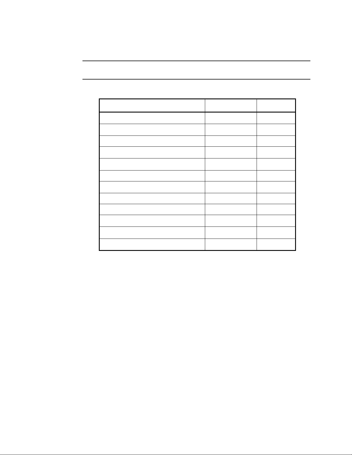
Table 2 lists the gases that the Model GD-K11D is capable of detecting. T able 2 also lists the
detection range, alarm point, and fail point for each target gas.
NOTE: Your Model GD-K11D is calibrated to only one of the gases listed below. A label
on the front of the instrument indicates the target gas of your Model GD-K11D.
Table 2: Model GD-K11D Target Gases, Detection Ranges, and Alarm Points
Target Gas Detection Range Alarm Point
Ammonia (NH
Arsine (AsH
)0 to 75.0 ppm 25.0 ppm
3
)0 to 1.00 ppm 0.30 ppm
3
Carbon monoxide (CO) 0 to 150 ppm 50 ppm
Chlorine (Cl
Chlorine trifluoride (ClF
)0 to 3.00 ppm 1.00 ppm
2
)0 to 1.00 ppm 0.30 ppm
3
Dichlorosilane (DCS) 0 to 15.0 ppm 5.0 ppm
Fluorine (F
)0 to 3.00 ppm 1.00 ppm
2
Hydrogen bromide (HBr) 0 to 9.00 ppm 3.00 ppm
Hydrogen chloride (HCl) 0 to 15.0 ppm 5.0 ppm
Phosphine (PH
Silane (SiH
Tungston hexafluoride (WF
)0 to 1.00 ppm 0.30 ppm
3
)0 to 15.0 ppm 5.0 ppm
4
)0 to 9.00 ppm 3.00 ppm
6
2 • Specifications Model GD-K11D Operator’s Manual
Page 7
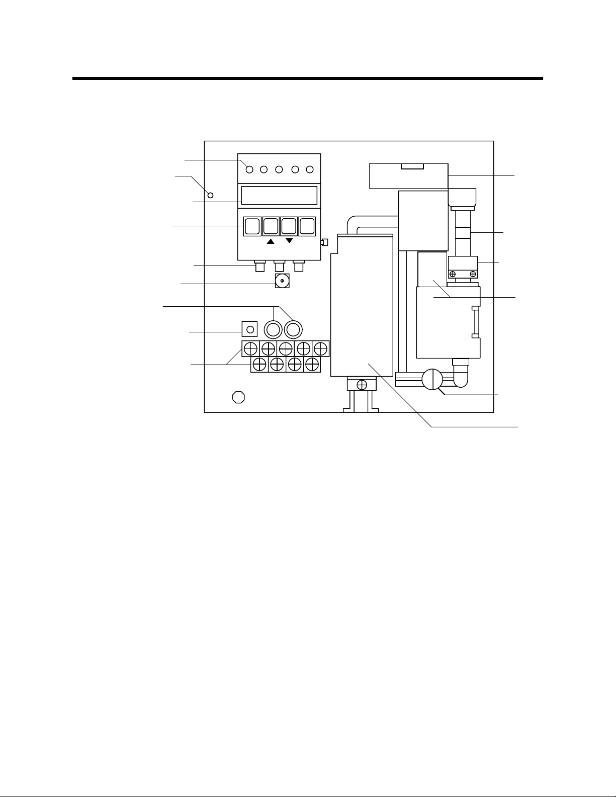
Description
Status lights
Low flow
light
Display screen
Program
buttons
Potentiometers
INT switch
Fuses
This section describes the components of the Model GD-K11D. The Model GD-K11D
consists of the housing, electrical system, flow system, and detection system.
AL ZERO SPAN SKIP
PW/TR
(PEAK)
MODE
GAIN ZERO SPAN
(ALP)
Flowmeter
SET
Flow sensor
Battery
Sensor
Power switch
Terminal strip
E
Flow adjust
valve
Pump
Figure 1: Model GD-K11D Component Location
Housing
The Model GD-K11D’s steel housing is radio frequency (RF)-resistant. It is suitable for
installation in indoor areas where general purpose equipment is in use.
The housing cover is hinged on the front bottom edge and is secured by a thumbscrew on
the top of the housing. The flowmeter , display screen, and status lights ar e visible thr ough
windows in the housing cover. The cover also includes two labels that indicate the target
gas and detection range of the Model GD-K11D.
Three 3/8 in. cable fittings on the bottom of the housing allow you to make external
wiring connections. The gas out fitting to the right of the cable fittings allows the gas
sample to exit the Model GD-K11D after the sample passes through the sample system.
The gas in fitting above and to the right of the gas out fitting allows the gas sample to
enter the Model GD-K11D. The gas in and gas out fittings accept 6 mm OD x 4 mm ID
PTFE tubing.
Two mounting flanges are attached to the back of the housing. The top flange includes
two mounting slots; the bottom flange includes two mounting holes. The flanges allow
you to install the Model GD-K11D to a vertical surface at the monitoring site.
Model GD-K11D Operator’s Manual Description • 3
Page 8

Electrical System
The Model GD-K11D’s electrical system consists of the terminal strip, power switch, and
fuses (see Figure 1.)
Terminal strip
The terminal strip allows you make external wiring connections to the Model GD-K11D.
The nine-point terminal strip is divided into two rows. The upper (five-point) terminal
strip is for connection to a recorder or a controlling device, which accepts a 4 to 20 mA
signal. The lower (four-point) terminal strip is for connection to incoming power and
external alarms.
NOTE: See the “Installation” section on page 8 for all wiring procedures.
Power switch
The power switch turns power to the Model GD-K11D on and off. The power switch is
ON when the toggle switch is in the UP position.
Fuses
Two extractor-type fuses protect the AC line circuitry from short circuit or overload. The
fuses are rated at 1 amp.
Flow System
The Model GD-K11D’s flow system consists of the pump, flowmeter, flow adjust valve,
flow sensor, low flow light, gas in fitting, and gas out fitting (see Figure 1). The gas in and
gas out fittings were described earlier.
Pump
The pump pulls the test sample into the Model GD-K11D.
Flowmeter
The flowmeter measures the flow rate to the sensor. A ball in the flowmeter column
indicates the flow rate. Two horizontal lines on the flowmeter mark the acceptable flow
rate. Use the flow adjust valve to keep the flowmeter ball between the two lines.
Flow adjust valve
The flow adjust valve allows you to adjust the flow rate to the sensor.
Flow sensor
The flow sensor activates the low flow alarm if the flowmeter ball drops below the visible
part of the flowmeter.
Low flow light
The low flow light is near the top left corner of the main circuit board. The low flow light
is directly above the 50-pin connector. The main circuit board is behind the amplifier
circuit board. The low flow light turns on if the flowmeter ball drops below the visible part
of the flowmeter.
4 • Description Model GD-K11D Operator’s Manual
Page 9

Detection System
The Model GD-K11D’s detection system consists of the sensor, lithium battery, amplifier,
and display board (see Figure 1.)
Sensor
Through a series of electrical and chemical reactions, the sensor produces an electrical
current that is proportional to the detection range of the target gas.
Electrodes within the sensor housing are surrounded by liquid electrolyte. The electrical
and chemical reactions are facilitated by the electrolyte.
Battery
The 3.6-volt lithium battery maintains the bias voltage on the sensor when the
Model GD-K11D is not receiving incoming power.
Amplifier
The amplifier is the circuit board to which the display board is mounted. The power
switch, fuses, and terminal strip are also mounted to the amplifier circuit board.
The amplifier converts the output of the sensor to a 4 to 20 mA signal (that is pr oportional
to the detection range of the Model GD-K11D) and converts the signal to a digital r eading
on the display screen.
CAUTION: The potentiometers on the amplifier circuit board are factory-set. Do not adjust them.
Display board
The display board includes the display screen, status lights, program buttons, and
adjustment potentiometers. The display board is mounted to the amplifier by standoffs.
NOTE: The display screen and status lights are visible through a window in the housing
cover.
Display screen
The display screen displays the current gas reading of the Model GD-K11D’s target gas.
The display screen also displays operational and error messages.
Model GD-K11D Operator’s Manual Description • 5
Page 10

Status lights
The display board includes five status lights. Table 3 lists each light and its function.
Table 3: Model GD-K11D Status Lights
Light Status
PW/TR
(power)
AL
(alarm)
ZERO • GD-K11D is prepared for adjustment of zero
SPAN • GD-K11D is prepared for adjustment of span
SKIP GD-11D is in maintenance mode (flashing light)
Program buttons
The display board includes five buttons. The MODE,
buttons are directly below the display screen. The TEST button is the red button near the
bottom right of the display board. Table 4 lists each button and its function.
Table 4: Model GD-K11D Program Buttons
Button Function
• live power is connected to GD-K11D and the
power switch is ON (solid light)
• fail condition (flashing light)
• gas alarm condition (solid light)
• over range condition (solid light)
setting (flashing light)
• GD-K11D accepted zero setting (solid light)
setting (flashing light)
• GD-K11D accepted span setting (solid light)
∆
(PEAK),
∇
, and SET (AL.P)
MODE Enters maintenance mode
∆
(PEAK)
∇
SET (AL.P) • Prepares a setting to be changed
TEST Enters alarm test mode
6 • Description Model GD-K11D Operator’s Manual
• Increases/changes the setting on the display
• Displays the peak reading
Decreases/changes the setting on the display
• Enters a new setting
• Displays the alarm point
Page 11

Adjustment potentiometers
The display board includes two potentiometers, which extend from the bottom of the
display board. Table 5 lists each potentiometer and its function.
Table 5: Model GD-K11D Adjustment Potentiometers
Potentiometer
1
Function
ZERO Adjusts the zero setting
2
SPAN
1
The GAIN potentiometer is for factory-use only. It is
for coarse span adjustments.
2
Only use the SPAN potentiometer if you cannot set
the span setting with the
Adjusts the span (response) setting
∆
and
∇
buttons.
INT switch
The INT switch is a 16-position rotary switch that allows you to perform particular tasks.
Use a small, flat-blade screwdriver to adjust the switch. The position that is at the top of
the switch is the currently selected position. If you are unsure which position is selected,
press the MODE button. If the switch is in any position other than 0, the position number
appears on the left side of the display screen.
Table 6 lists switch positions for common tasks. The table also references step-by-step
procedures for each task.
CAUTION: Switch positions not listed in this table are for factory use. Only use the switch
positions listed is this table and described later in this manual.
Switch position “0” is for normal operation (detection mode). If you adjust the INT
switch, always return it to the “0” position after you complete the task.
Table 6: Model GD-K11D INT switch positions
Position Task Refer to
0 Detection mode (normal operation) page 1
1 Calibration with gas sample page 22
2 Adjust the alarm point page 13
3 Adjust the alarm delay page 14
5Turn on/off peak reading feature page 13
7 Adjust the alarm type (high/low) page 15
Model GD-K11D Operator’s Manual Description • 7
Page 12

Installation
p
This section describes how to install the Model GD-K11D at the monitoring site. This
section includes procedures to mount the Model GD-K11D, connect sample lines to the
Model GD-K11D, and make power and other wiring connections to the Model GD-K11D.
Mounting the Model GD-K11D
CAUTION: The Model GD-K11D is suitable for installation in indoor areas where general
purpose equipment is in use.
1. Select a mounting site that is representative of the monitoring environment. Consider
the following when you select the mounting site.
• Select a site where the Model GD-K11D is not likely to be bumped or disturbed.
Make sure there is sufficient room to make wiring and sample line connections at
the bottom of the transmitter. Also make sure there is sufficient room to open the
housing cover and perform start-up, maintenance, and calibration procedures.
• Select a site near the sampling area.
NOTE: If your application does not require a specific mounting site, mount the
transmitter at approximately eye level.
8.2
1.2
0.3 dia.
(4 times)
9.8
.48
9.1
.45
GAS DETECTOR
7.3
MODEL
GD-K11D
7.3
8.4
Note 1: All measurements in inches.
Note 2: Model GD-K11D is 4.1 inches deep.
Note 3: Allow at least 2 feet in front of
Model GD-K11D to o
en housing door.
Figure 2: Mounting the Model GD-K11D
8 • Installation Model GD-K11D Operator’s Manual
Page 13

2. Use two screws through the slot cutouts at the top of the housing to secure the
housing to a vertical surface at the mounting site (see Figure 2.)
3. Use two screws through the mounting holes at the bottom of the housing to support
the installation of the Model GD-K11D (see Figure 2.)
Connecting the Sample Lines to the Model GD-K11D
1. Attach 4 x 6 mm PTFE teflon tubing to the gas in fitting. Place the opposite end of the
tubing at the sampling area.
CAUTION: Avoid loops or slumps in the incoming sample line. To reduce response time, keep the
incoming sample line as short as possible.
2. Attach 4 x 6 mm PTFE teflon tubing to the gas out fitting. Route the opposite end of
the tubing to an open area where the sample can safely disperse.
Wiring the Model GD-K11D
This section describes procedures to connect AC power to the Model GD-K11D. This
section also describes optional procedures to connect a controller or recorder and external
alarm device to the Model GD-K11D. Figure 3 illustrates wiring connections to the
Model GD-K11D.
WARNING: Always verify that the Model GD-K11D’s power switch is in the OFF
position before you make wiring connections to the Model GD-K11D.
CONTROLLER/
RECORDER
+
output
4-20
mA
E
AC POWER
115V, 60 HZ.
GROUND
NEUTRAL
HOT
POWER
SOURCE
ALARM
DEVICE
CAUTION: If the alarm device draws more than 1 amp, use the
alarm contacts to control a relay with an appropriate contact rating.
Figure 3: Wiring the Model GD-K11D
Model GD-K11D Operator’s Manual Installation • 9
Page 14

Connecting AC power
1. Loosen the thumbscrew at the top of the housing.
2. Rotate the housing cover toward the bottom of the housing to gain access to the
terminal strip.
3. Verify that the Model GD-K11D’s power switch is in the OFF position.
4. Unscrew and remove the two screws that secure the terminal strip’s protective cover,
then remove the protective cover.
5. Guide the AC power cord through an unused conduit fitting at the bottom of the
housing.
6. Connect the AC line to the lower row of the terminal strip as shown in Figure 3.
7. Connect the AC line’s ground wire to the ground screw as shown in Figure 3. The
ground screw is below and to the left of the terminal strip.
8. If you do not plan to make any more wiring connections to the terminal strip, position
the protective cover over the terminal strip, then secure the cover with the two screws
you removed in step 4.
Connecting the Model GD-K11D to a controller or recorder
Perform the following procedure to connect a controller or recording device to the Model
GD-K11D. The output at the Model GD-K11D’s terminal strip is a 4 to 20 mA signal that is
proportional to the detection range.
1. Guide the wiring from the controller or recording device through an unused conduit
fitting at the bottom of the housing.
CAUTION: Do not route wiring from the AC power source and the controller or recorder
through the same conduit fitting. The power cable may disrupt the transmission of
the 4 to 20 mA signal to the controller or recorder.
2. Connect the leads to the upper row of the terminal strip as shown in Figure 3.
Connecting the Model GD-K11D to an external alarm device
CAUTION: The maximum current rating of the normally-open, dry contacts is 1 amp. If the
alarm device exceeds this rating, use the alarm contacts to control a relay with an
appropriate current rating.
1. Guide the wiring of the external alarm through an unused conduit fitting at the bottom
of the housing.
CAUTION: If the external alarm device is powered by AC current, do not route wiring from the
external alarm and the controller or recorder (if applicable) through the same conduit
fitting. The power wiring may disrupt the transmission of the 4 to 20 mA signal to
the controller or recorder.
2. Connect the leads to the lower row of the terminal strip as shown in Figure 3.
10 • Installation Model GD-K11D Operator’s Manual
Page 15

Start Up
This section describes procedures to start up the Model GD-K11D and place the Model
GD-K11D into normal operation.
Introducing Incoming Power
1. Complete the installation procedures described earlier in this manual.
2. Verify that the power wiring is correct and secure (see the “Installation” section on
page 8.)
3. Turn on or plug in the incoming power at the power source end, then place the Model
GD-K11D’s power switch in the ON position.
4. Verify that the PW/TR (power) light is on.
5. Verify that the flowmeter ball is between the two lines on the flowmeter. If necessary,
use the flow adjust valve to adjust the flow rate to the sensor, so the flowmeter ball is
between the two lines.
6. Verify that the incoming sample line is not leaking. To test the sample line, plug the
open end of the sample line with your thumb. If the flowmeter ball drops to the
bottom of the flowmeter, the incoming sample line is not leaking.
CAUTION: Allow the Model GD-K11D to warm up for 30 minutes (2 hours for ammonia
transmitters) before you continue with the next section. If the sensor keeper batteries
are dead and the Model GD-K1 1D has been off power for an extended period of time,
allow the Model GD-K11D to warm up overnight.
Setting the Zero Reading
CAUTION: If you suspect the presence of toxic gas in the monitoring environment, use the
calibration kit and the zero air calibration cylinder to introduce “fresh air” to the
sensor and verify an accurate zero setting.
1. Verify that the Model GD-K11D is in a fresh air environment (environment known to
be free of toxic gas.)
2. Press and hold down the MODE button until 1. appears on the display screen
(approximately 3 seconds).
The SKIP light flashes.
3. Press the
4. Press the SET button.
The ZERO light flashes, and the gas reading appears on the display screen. The Model
GD-K11D is prepared to adjust the zero reading.
5. Use the ZERO potentiometer to adjust the display reading to zero.
∆
button twice to display 3.
Model GD-K11D Operator’s Manual Start Up • 11
Page 16

6. Press the MODE button.
The ZERO light turns off, and 3. appears on the display screen.
NOTE: The purpose of this procedure is to set the zero r eading only. It is not necessary to
set the span (response) reading at this time.
7. Press the MODE button for approximately 3 seconds to exit maintenance mode and
return to the normal screen.
8. Rotate the housing cover up to its original position, then tighten the thumbscrew at
the top of the housing to secure the cover to the housing.
12 • Start Up Model GD-K11D Operator’s Manual
Page 17

Operation
This section describes procedures to display the peak reading, and to adjust the alarm
point, alarm delay, and alarm type.
Displaying the Peak Reading
The Model GD-K11D defines the peak reading as the highest reading above the alarm point
since the last time the peak reading was reset. A reading must remain above the alarm
point for a period longer than the alarm delay (default is 3 seconds) before the Model
GD-K11D compares the gas reading to the current peak reading.
You must also “turn on” the peak reading feature in order for the Model GD-K11D to
recognize and save peak readings.
To turn on the peak reading feature:
1. Adjust the INT switch to the “5” position. The INT switch is the rotary switch located
on the amplifier circuit board (see Figure 1, Model GD-K11D Component Location.)
The SKIP light flashes. If 1 appears on the display screen, the peak hold feature is
turned on. If not, continue with step 2.
2. Press the MODE button, and make sure 5 appears on the left side of the display
screen.
3. Press the ∆ button to display 1 on the screen.
4. Press the SET button.
The SPAN light turns on.
5. Return the INT switch to the “0” position to return to normal operation.
The SPAN and SKIP lights turns off.
To display the peak reading:
1. From the normal screen, press the ∆ (PEAK) button.
The peak reading displays.
2. To reset the peak reading, press and hold down the ∆ (PEAK) and SET buttons until
the peak reading is cleared from the display screen.
Adjusting the Alarm Point
The factory-set alarm point is one-third of the fullscale value. Alarm points for the Model
GD-K11D’s target gases are listed in Table 2, Model GD-K11D Target Gases, Detection
Ranges, and Alarm Points. The range of acceptable alarm points is 10% to 100% of the
fullscale value.
To display the current alarm point, from the normal screen press and hold down the SET
button until the alarm point appears on the display screen. Release the SET button to
return to the normal screen.
To adjust the alarm point:
1. Loosen the thumbscrew at the top of the housing.
2. Rotate the housing cover toward the bottom of the housing to gain access to the
interior of the Model GD-K11D.
Model GD-K11D Operator’s Manual Operation • 13
Page 18

3. Adjust the INT switch to the “2” position.
The current alarm point appears on the display screen, and the SKIP light flashes.
4. Press the MODE button, and make sure 2 appears on the left side of the display
screen.
5. Use the ∆ and ∇ buttons to adjust the alarm point to the setting you want.
6. Press the SET button to confirm the new alarm point.
The SPAN light turns on indicating that the Model GD-K11D accepted the new
setting.
7. Return the INT switch to the “0” position to return to normal operation.
The SPAN and SKIP lights turns of.
8. Rotate the housing cover up to its original position, then secure the cover to the
housing with the thumbscrew.
Adjusting the Alarm Delay
The factory-set alarm delay is 3 seconds. The range of acceptable alarm delay settings is
0.5 to 60 seconds.
1. Loosen the thumbscrew at the top of the housing.
2. Rotate the housing cover toward the bottom of the housing to gain access to the
interior of the Model GD-K11D.
3. Adjust the INT switch to the “3” position.
The current alarm delay appears on the display screen, and the SKIP light flashes.
4. Press the MODE button, and make sure 3 appears on the left side of the display
screen.
5. Use the ∆ and ∇ buttons to adjust the alarm delay to the setting you want.
6. Press the SET button to confirm the new alarm delay.
The SPAN light turns on indicating that the Model GD-K11D accepted the new
setting.
7. Return the INT switch to the “0” position to return to normal operation.
The SPAN and SKIP lights turns of.
8. Rotate the housing cover up to its original position, then secure the cover to the
housing with the thumbscrew.
14 • Operation Model GD-K11D Operator’s Manual
Page 19

Adjusting the Alarm Type
You can program the Model GD-K11D’s alarm to activate on increasing readings or
decreasing readings. The factory-set alarm type is increasing.
1. Loosen the thumbscrew at the top of the housing.
2. Rotate the housing cover toward the bottom of the housing to gain access to the
interior of the Model GD-K11D.
3. Adjust the INT switch to the “7” position.
The current alarm type displays, and the SKIP light flashes. H (“high”) indicates an
increasing setting; L (“low”) indicates a decreasing setting.
4. Press the MODE button, and make sure 7 appears on the left side of the display
screen.
5. Use the ∆ or ∇ button to display the alternate alarm type.
6. Press the SET button to confirm the new alarm type.
The SPAN light turns on indicating that the Model GD-K11D accepted the new
setting.
7. Return the INT switch to the “0” position to return to normal operation.
The SPAN and SKIP lights turns of.
8. Rotate the housing cover up to its original position, then secure the cover to the
housing with the thumbscrew.
Model GD-K11D Operator’s Manual Operation • 15
Page 20

Alarms
This section describes the Model GD-K11D’s visual indications for normal, alarm, and fail
conditions. This section also suggests response to these conditions.
Alarm Indications
Table 5 lists the indications for normal, alarm and fail conditions.
The Model GD-K11D includes an alarm delay feature. The alarm indications listed below
are delayed by 3 seconds once the Model GD-K11D recognizes an alarm or fail condition.
Table 7: Model GD-K11D Alarm Indications
Condition Cause(s) Indications Alarm Contacts
Normal • Start up complete
• No gas or fail alarms
Gas
Alarm
Fail
Alarm
Low Flow
Alarm
1
The PW/TR (power) light flashes.
Increasing gas reading at
or above alarm point
Disconnected sensor • E-01 on screen
Low flow rate • E-05 on screen
PW/TR light De-energized
AL light Energized
• PW/TR light
• AL light
• 0.5 mA output
• PW/TR light
• Low flow (red) light
on main board
• 0.5 mA output
Responding to Alarms
This section suggests response to gas and fail alarms.
Responding to gas alarms
De-energized
1
De-energized
1
1. Follow your established procedure for an increasing toxic gas condition.
2. When the display reading falls below the alarm point, the alarm circuit automatically
resets itself. The AL (alarm) light turns off.
Responding to fail alarms
1. Set the correct flow rate with the flow adjust valve.
2. If you cannot set the correct flow rate, check the sample lines for obstructions or kinks.
3. Calibrate the Model GD-K11D as described on page 21.
4. If the fail condition continues, replace the sensor as described on page 18.
5. If the fail condition continues, contact RKI Instruments, Inc., for further instruction.
16 • Alarms Model GD-K11D Operator’s Manual
Page 21

Maintenance
This section describes maintenance procedures for the Model GD-K11D. It includes
preventive maintenance and troubleshooting procedures.
Preventive Maintenance
This section describes a preventive maintenance schedule to ensure the optimum
performance of the Model GD-K11D. It includes daily, quarterly, and biannual
procedures.
Daily
1. Verify that the PW/TR (power) light is on. If the power light is not on, see the
2. Verify that the flowmeter ball is between the two lines on the flowmeter. If necessary,
3. Verify a display reading of 0 PPM. Investigate significant changes in the reading.
Quarterly
If you are not in a sensor exchange program, set the sensor’s K number as described on
page 19, then calibrate the Model GD-K11D as described on page 21.
troubleshooting guide in this manual.
use the flow adjust valve to adjust the flow rate, so the flowmeter ball is between the
two lines.
Biannually
If you are in a sensor exchange program, replace the sensor as described on page 18.
As required
This procedure describes a test to verify that the alarm circuit is operating properly.
NOTE: This test duplicates an alarm condition. Any external alarms wired to the Model
GD-K11D will activate during this test.
1. Loosen the thumbscrew at the top of the housing.
2. Rotate the housing cover toward the bottom of the housing to gain access to the
interior of the Model GD-K11D.
3. Press and hold down the TEST button. The TEST button is the red button on the right
side of the display panel.
The SKIP light turns on indicating that the Model GD-K11D is in alarm test mode.
4. While pressing the TEST button, press the ∆ button until the display reading is greater
than the alarm point.
After the alarm delay, the AL (alarm) light turns on and the relay contacts on the
terminal strip energize. Any external alarm devices wir ed to the r elay contact activate
when the relays contacts energize.
5. Release the TEST button to return to measuring mode (normal operation).
The display reading decreases to the normal level, and the alarm circuit automatically
resets itself.
6. Rotate the housing cover up to its original position, then tighten the thumbscrew at
the top of the housing to secure the cover to the housing.
Model GD-K11D Operator’s Manual Maintenance • 17
Page 22

Troubleshooting
The troubleshooting table describes error messages, symptoms, probable causes, and
recommended action for problems you may encounter with the Model GD-K11D.
Table 8: Troubleshooting the Model GD-K11D
Symptoms Probable Causes Recommended Action
• E-00 on display screen • Memory error 1. Contact RKI Instruments, Inc.
• E-01 on display screen
• PW/TR light is flashing
• Output is 0.5 mA
• E-05 on display screen
• PW/TR light is flashing
• Output is 0.5 mA
• Low flow light is on
• Flowmeter indicates low
flow rate
• E-06 on display screen • Communication error 1. Verify that wiring to the 4-20mA output
• Unable to zero or span
reading during
calibration
• Display screen does not
indicate gas reading
• Sensor is disconnected 1. Verify that the sensor connector is
• Sample line is
obstructed
• Pump is disconnected
• Pump is failing
• Calibration cylinder is
low, out-dated, or
defective
• Sample line is
obstructed
• Model GD-K11D is in
maintenance mode
securely connected to the sensor.
2. Calibrate the sensor.
3. If difficulties continue, contact RKI.
1. Set the correct flow rate with the flow
adjust valve.
2. Check the sample line for obstructions or
kinks.
3. Verify that the pump connector is
plugged into the pump socket (PUMP).
4. If difficulties continue, contact RKI.
terminales is correct.
2. If difficulties continue, contact RKI.
1. Verify that the calibration cylinder
contains an adequate supply of a fresh
calibration sample.
2. If necessary, set the correct flow rate with
the flow adjust valve.
3. If you cannot set the correct flow rate,
check the calibration tubing for
obstructions or kinks.
4. If difficulties continue, contact RKI.
1. Verify that the INT switch is in the “0”
position. Adjust the switch if necessary.
2. Press the MODE button until the normal
screen appears.
• on display screen • Abnormal indication
• LCD (display) not
working
1. Set the sensor’s zero reading as described
on page 11.
2. If difficulties continue, contact RKI.
Replacing Components
The section includes procedures to replace the sensor, pump, and fuse.
Replacing the sensor
This section includes procedures to remove the sensor, install the replacement sensor,
enter the new K number, and set the zero reading.
Removing the sensor
1. Loosen the thumbscrew at the top of the housing.
2. Rotate the housing cover toward the bottom of the housing to gain access to the
interior of the Model GD-K11D.
3. Place the power switch in the OFF position.
18 • Maintenance Model GD-K11D Operator’s Manual
Page 23

4. Pull the metal restraining bracket that secures the sensor in the housing away from
the sensor, then rotate the bracket to the right.
5. Slide the sensor to the left (toward the pump), then remove the sensor from the flow
chamber.
6. Disconnect the connector from the sensor, then remove the sensor from the housing.
Installing the replacement sensor
1. Connect the connector to the replacement sensor, then install the sensor in the same
position as the original sensor.
2. Place the metal restraining bracket in its original position to secure the sensor within
the housing.
3. Place the power switch in the ON position.
4. Allow the sensor to warm up for 30 minutes (2 hours for ammonia sensors) before
you continue with this procedure.
Entering the new K number
Each sensor is shipped with a K number written on the label. The K number is established
at the factory at the time of calibration. The K number allows the Model GD-K11D to
automatically set the span setting without introducing calibrating gas.
CAUTION: The K number is only valid for 3 months after shipment from the factory. If you
suspect the replacement sensor is beyond this 3-month limit, calibrate the
replacement sensor (see page 21) after you enter the K number.
1. Press the MODE button until the SKIP light begins flashing and 1. appears on the
display screen.
2. Press the ∆ button three times to display 4. on the screen.
3. Press the SET button to display the K number of the previous sensor.
4. Use the ∆ and ∇ buttons to adjust the value on the display screen to the K number of
the replacement sensor.
5. Press the SET button to enter the new K number.
The SPAN light is on steady (instead of flashing) to indicate the new K number is
entered.
6. Press the MODE button to display 4.
Setting the zero reading
CAUTION: If you suspect the presence of toxic gas in the monitoring environment, use the
calibration kit and the zero air calibration cylinder to introduce “fresh air” to the
sensor and verify an accurate zero setting.
1. Verify that the Model GD-K11D is in a fresh air environment (environment known to
be free of toxic gas.)
2. Press the
∇ button to display 3.
3. Press the SET button.
The ZERO light flashes, and the gas reading appears on the display screen. The Model
GD-K11D is prepared to adjust the zero reading.
Model GD-K11D Operator’s Manual Maintenance • 19
Page 24

4. Use the ZERO potentiometer to adjust the display reading to zero.
5. Press the MODE button.
The ZERO light turns off, and 3. appears on the display screen.
6. Press the MODE button for approximately 3 seconds to exit maintenance mode and
return to the normal screen (measuring mode).
7. Rotate the housing cover up to its original position, then tighten the thumbscrew at
the top of the housing to secure the cover to the housing.
Replacing the pump
1. Loosen the thumbscrew at the top of the housing.
2. Rotate the housing cover toward the bottom of the housing to gain access to the
interior of the Model GD-K11D.
3. Place the power switch in the OFF position.
4. Disconnect the pump connector from the socket on the amplifier circuit board. The
socket is marked PUMP and is to the right of the fuses.
5. Loosen the captive screw at the bottom of the pump cover, then rotate the cover
toward the top of the housing.
6. Remove the pump.
7. Place the replacement pump in the same position as the original pump.
8. Rotate the pump cover down to its original position, then secure the cover with the
captive screw.
9. Connect the pump connector to the socket marked PUMP on the amplifier circuit
board.
10. Place the power switch in the ON position.
11. Rotate the housing cover up to its normal position, then secure the cover to the
housing with the thumbscrew.
Replacing the fuses
1. Loosen the thumbscrew at the top of the housing.
2. Rotate the housing cover toward the bottom of the housing to gain access to the
interior of the Model GD-K11D.
3. Place the power switch in the OFF position.
4. Use a screwdriver to slightly push the fuse holder down, then rotate the holder to the
left.
5. Remove the fuse holder from the Model GD-K11D, then remove the fuse from the
holder.
6. Install the replacement fuse in the fuse holder, then insert the fuse holder into its
original position.
7. Use a screwdriver to slightly push the fuse holder down, then rotate the holder to the
right.
8. Place the power switch in the ON position.
9. Rotate the housing cover up to its normal position, then secure the cover to the
housing with the thumbscrew.
20 • Maintenance Model GD-K11D Operator’s Manual
Page 25

Calibration
This section describes how to calibrate the Model GD-K11D. It includes procedures to
prepare for calibration, set the zero r eading, set the r esponse (span) r eading, and r eturn to
normal operation.
WARNING: The Model GD-K11D is not an active gas monitoring device during the
calibration procedure.
Preparing for Calibration
NOTE: This procedure describes calibration using the RKI calibration kit that includes a
“demand flow” regulator. A calibration kit that uses a gas collection bag is also
available. Contact RKI Instruments, Inc., for more information concerning the
gas collection bag accessory.
1. Screw the regulator into the zero air calibration cylinder.
2. Disconnect the incoming sample line from the Model GD-K11D’s gas in fitting, then
connect the calibration kit sample tubing to the gas in fitting.
NOTE: Do not connect the tubing from the gas in fitting to the regulator at this time.
3. Loosen the thumbscrew on the top of the housing, then rotate the housing cover
toward the bottom of the housing.
Setting the Zero Reading
1. Press and hold down the MODE button until 1. appears on the display screen
(approximately 3 seconds).
The SKIP light flashes.
2. Press the ∆ button twice to display 3.
3. Press the SET button.
The ZERO light flashes, and the gas reading appears on the display screen.
4. Connect the tubing from the Model GD-K11D’s gas in fitting to the regulator. The
Model GD-K11D’s pump automatically begins pulling the calibrating sample fr om the
zero air calibration cylinder when you connect the tubing to the regulator.
5. When the display reading stabilizes, use the ZERO potentiometer to adjust the
display reading to zero.
6. Press the MODE button.
The ZERO light turns off, and 3. appears on the display screen.
7. Disconnect the sample tubing from the regulator, then unscrew the regulator from the
zero air calibration cylinder. Leave the tubing connected to the Model GD-K11D.
8. Press the MODE button for approximately 3 seconds to exit maintenance mode and
return to the normal screen.
Model GD-K11D Operator’s Manual Calibration • 21
Page 26

Setting the Response (Span) Reading
1. Adjust the INT switch to the “1” position. The INT switch is the rotary switch located
on the amplifier circuit board (see Figure 1, Model GD-K11D Component Location).
The display reading, SPAN light, and SKIP light flash.
2. Press the MODE button, and make sure 1 appears on the left side of the display
screen.
3. Screw the regulator into the calibration cylinder.
4. Connect the tubing from the Model GD-K11D’s gas in fitting to the regulator. The
pump begins pull the sample from the calibration cylinder.
The display reading increases as the sensor begins to sample the calibrating gas.
When the display reading reaches 20% of fullscale, the reading stops flashing.
NOTE: The reading must be at least 20% of fullscale before the Model GD-K11D will
allow adjustment of the span setting.
5. When the display reading stabilizes, use the ∆ and ∇ buttons to adjust the display
reading to match the concentration of the calibration cylinder.
NOTE: If you cannot adjust the display reading to the concentration of the calibration
cylinder with the ∆ and ∇ buttons, adjust the reading to be in the middle of the
adjustment range, then adjust the reading with the span potentiometer.
6. Press the SET button to set the response (span) reading.
The SPAN light is on steady indicating that the Model GD-K11D accepted the span
setting.
7. Disconnect the sample tubing from the regulator, then disconnect the opposite end of
the sample tubing from the Model GD-K11D’s gas in fitting.
8. Reattach the sample line to the gas in fitting.
Returning to Normal Operation
1. Unscrew the regulator from the calibration cylinder.
NOTE: If the display reading is above the alarm point when you return to the normal
screen, the Model GD-K11D will initiate an alarm condition.
2. Return the INT switch to the “0” position to return to normal operation.
The SPAN and SKIP lights turn off.
3. Rotate the housing cover up to its normal position, then secure the cover to the
housing with the thumbscrew.
4. Store the components of the calibration kit in a safe and convenient place.
5. Verify that the display reading decreases and stabilizes at zero.
22 • Calibration Model GD-K11D Operator’s Manual
 Loading...